

Page 1
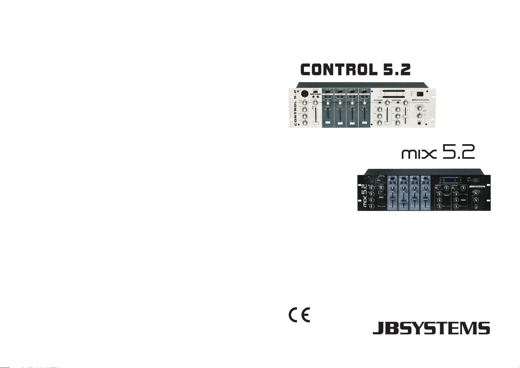
5Channel - 2Zone Mixer
WWW.BEGLEC.COM
Copyright © 2010 by BEGLEC NV
‘t Hofveld 2C ~ B1702 Groot-Bijgaarden ~ Belgium
Reproduction or publication of the content in any manner, without express permission of the publisher, is prohibited.
Version: 1.0
Operation Manual
Mode d'emploi
Gebruiksaanwijzing
Bedienungsanleitung
Manual de instrucciones
Manual do utilizador
The Power Source for DJ’s
EN
FR
NL
DE
ES
PT
Page 2
EN - DISPOSAL OF THE DEVICE
Dispose of the unit and used batteries in an environment friendly manner
according to your country regulations.
FR - DÉCLASSER L’APPAREIL
Débarrassez-vous de l’appareil et des piles usagées de manière écologique
Conformément aux dispositions légales de votre pays.
NL - VERWIJDEREN VAN HET APPARAAT
Verwijder het toestel en de gebruikte batterijen op een milieuvriendelijke
manier conform de in uw land geldende voorschriften.
DU - ENTSORGUNG DES GERÄTS
Entsorgen Sie das Gerät und die Batterien auf umweltfreundliche Art und
Weise gemäß den Vorschriften Ihres Landes.
ES - DESHACERSE DEL APARATO
Reciclar el aparato y pilas usadas de forma ecologica conforme a las
disposiciones legales de su pais.
PT - COMO DESFAZER-SE DA UNIDADE
Tente reciclar a unidade e as pilhas usadas respeitando o ambiente e em
conformidade com as normas vigentes no seu país.
Page 3
ENGLISH OPERATION MANUAL
OPERATION MANUAL
FEATURES
2 Independent Zones, each with balanced XLR-output (+unbalanced on cinch)
Each zone has 3band tone controls, balance, volume and mono/stereo switch
11 inputs on 5 Channels (5 balanced mic + 4line + 2phono)
1Microphone with 3band tone control and zone assignable adjustable talkover.
Every Channel can be assigned to zone A, zone B or both.
Every Channel has individual peak and signal present leds.
Gain levels and 45mm faders on all channels
PFL with rotary selector, cue level adjustment and 6.3mm headphones jack.
2 independent record outputs without Channel1 microphone and free from talkover
muting.
BEFORE USE
CHECK THE CONTENTS:
Check that the carton contains the following items:
CONTROL5.2 / MIX5.2 Mixer unit
Operating instructions
Mains cable
SAFETY INSTRUCTIONS:
CAUTION
The lightning flash with arrowhead symbol within the equilateral triangle is
intended to alert the use or the presence of un-insulated “dangerous voltage”
within the product’s enclosure that may be of sufficient magnitude to
constitute a risk of electric shock.
The exclamation point within the equilateral triangle is intended to alert the
user to the presence of important operation and maintenance (servicing)
instructions in the literature accompanying this appliance.
This symbol means: indoor use only.
This symbol means: Read instructions.
To prevent fire or shock hazard, do not expose this appliance to rain or moisture.
To avoid condensation to be formed inside, allow the unit to adapt to the
surrounding temperatures when bringing it into a warm room after transport.
Condense sometimes prevents the unit from working at full performance or may
even cause damages.
This unit is for indoor use only.
CAUTION: To reduce the risk of electric
shock, do not remove any cover. No userserviceable parts inside. Refer servicing to
qualified service personnel only.
ENGLISH OPERATION MANUAL
Don’t place metal objects or spill liquid inside the unit. No objects filled with liquids,
such as vases, shall be placed on this appliance. Electric shock or malfunction may
result. If a foreign object enters the unit, immediately disconnect the mains power.
No naked flame sources, such as lighted candles, should be placed on the
appliance.
Don’t cover any ventilation openings as this may result in overheating.
Prevent use in dusty environments and clean the unit regularly.
Keep the unit away from children.
Inexperienced persons should not operate this device.
Maximum save ambient temperature is 45°C. Don’t use this unit at higher ambient
temperatures.
Minimum distances around the apparatus for sufficient ventilation is 5cm.
Always unplug the unit when it is not used for a longer time or before you start
servicing.
The electrical installation should be carried out by qualified personal only, according
to the regulations for electrical and mechanical safety in your country.
Check that the available voltage is not higher than the one stated on the rear panel
of the unit.
The socket inlet shall remain operable for disconnection from the mains.
The power cord should always be in perfect condition: switch the unit immediately
off when the power cord is squashed or damaged.
Never let the power-cord come into contact with other cables!
In order to prevent electric shock, do not open the cover. Apart from the mains fuse
there are no user serviceable parts inside.
Never repair a fuse or bypass the fuse holder. Always replace a damaged fuse
with a fuse of the same type and electrical specifications!
In the event of serious operating problems, stop using the appliance and contact
your dealer immediately.
Please use the original packing when the device is to be transported.
Due to safety reasons it is prohibited to make unauthorized modifications to the
unit.
INSTALLATION GUIDELINES:
Install the unit in a well-ventilated location where it will not be exposed to high
temperatures or humidity.
Placing and using the unit for long periods near heat-generating sources such as
amplifiers, spotlights, etc. will affect its performance and may even damage the
unit.
The unit can be mounted in 19-inch racks. Attach the unit using the 4 screw holes
on the front panel. Be sure to use screws of the appropriate size. (screws not
provided)
Take care to minimize shocks and vibrations during transport.
When installed in a booth or flight case, please make sure to have good ventilation
to improve heat evacuation of the unit.
To avoid condensation to be formed inside, allow the unit to adapt to the
surrounding temperatures when bringing it into a warm room after transport.
Condense sometimes prevents the unit from working at full performance.
JB SYSTEMS® 1/36 CONTROL5.2 / MIX5.2 MIXER
JB SYSTEMS® 2/36 CONTROL5.2 / MIX5.2 MIXER
Page 4
ENGLISH OPERATION MANUAL
ENGLISH OPERATION MANUAL
CLEANING THE MIXER:
Clean by wiping with a polished cloth slightly dipped with water. Avoid getting water
inside the unit. Do not use volatile liquids such as benzene or thinner which will
damage the unit.
CONNECTIONS
Except for microphones, headphone and zone outputs, all connections are cinch.
Use good quality cinch-cinch cables to prevent bad audio quality. (example: JB
Systems code: 2-0370)
For more information on connections, please refer to the next chapter.
Be sure to turn off the mixer before you make changes to the different connections.
In this manual we talk about “line inputs”. This is a global name for inputs with a level
between 750mV and 2V. This includes tuners, videos, CD-players, etc.
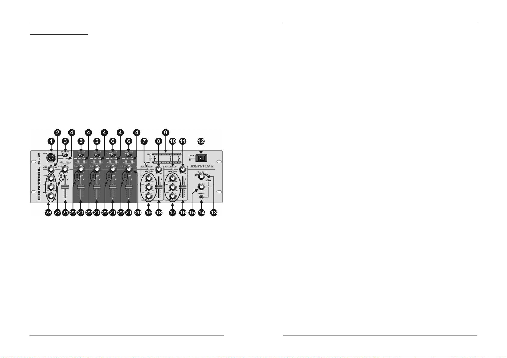
FRONT PANEL
1. DJ MICRO input: The DJ micro can be connected to the XLR/Jack input on the
front plate or to the stereo jack on rear panel. This input is balanced but accepts
any kind of microphone equipped with an XLR or jack connector.
2. TALKOVER level: When you switch the talkover(3) on, you can adjust the
amount of muting on input channels 2 to 5. The more you turn to the right, the
more these channels are muted while talking through the DJ Micro(1).
3. TALKOVER switch: Use this switch to automatically mute the input channels 2 to
5 while you are talking through the DJ microphone. Use the zone selectors(4) to
choose on which output the talkover should work.
Attention: the talkover will only work on the zone you selected for the DJ Micro. The other zone
won’t be affected.
4. ZONE switch: for every input channel you can choose to which zone (master) it
should be routed. This means that you can use this mixer to serve two different
rooms with completely different music!
Example:
You want channels 2&3 to be routed to Master A (room1). Channels 4&5 must
be routed to Master B (room2). But you want to be able to make
announcements in both rooms. This is what you should do:
Select “zone A” on channels 2&3
Select “zone B” on channels 4&5
Select “zone A” and “zone B” on DJ Micro input.
Now you can do announcements in both rooms, while the music you play in
both rooms is completely different.
5. INPUT SELECTOR switch: On channels 2 and 3 you can choose between line
or balanced micro inputs.
6. INPUT SELECTOR switch: On channels 4 and 5 you can choose between line
or balanced micro inputs but you can also connect a turntable. (line/phono switch
on the back)
7. MONO/STEREO switch: used to switch Master A in mono or stereo mode.
8. BALANCE: used to adjust the balance between left and right output on Master A.
9. VU-meters: Used to monitor the level of the audio signals selected with the CUE
selector(13). With the channel faders you can change the input level of each
connected audio source. Make sure the levels do not exceed 0dB (or 100%). The
audio risks to be distorted when the signal level comes in the red zone of the VUmeter.
10.MONO/STEREO switch: used to switch Master B in mono or stereo mode.
11.BALANCE: used to adjust the balance between left and right output on Master B.
12.POWER switch: Used to turn the power of the mixer on and off.
13.CUE SELECTOR switch: Used to select the source you want to monitor. You
can listen to any input channel while its channel fader is closed.
14.CUE LEVEL: Used to control the output level of the headphone output.
15.HEADPHONE jack: You can connect any modern stereo headphone to this
6.3mm jack. Together with the cue selector (13) and the cue level (14) you can
use it to listen to the selected input channel.
16.MASTER B level: Used to adjust the output level of Master B.
17.3BAND TONE control: use these 3 controls to modify the audio signal of Master
B to your personal taste.
18.MASTER A level: Used to adjust the output level of Master A.
19.3BAND TONE control: use these 3 controls to modify the audio signal of Master
A to your personal taste.
20.GAIN controls: Used to set the sensitivity of each channel separately. Based on
the information from the VU meters(9) and the peak led(22) you can adjust the
channel sensitivity.
21.CHANNEL FADERS: Used to set the level of each channel separately.
22.PEAK & SIGNAL LEDS: all channels are equipped with a peak and signal led:
Signal led: The green signal led indicates that a music signal is present at this
channel input.
Peak led: The red peak led indicates that the input signal is too high. Make sure
that the peak led only turns on from time to time. When the peak led is on for
longer periods, you are urged to lower the input signal using the GAIN
control(20).
23.3BAND TONE control: you can use these 3 controls to modify the audio signal of
the DJ micro to your personal taste or to remove feedback from the microphone.
Note: Feedback is where an acoustic signal is amplified over and over again until it develops
rapidly into a loud screech: Reduce the gain on your microphone channel and/or try cutting HF
from your tone controls.
JB SYSTEMS® 3/36 CONTROL5.2 / MIX5.2 MIXER
JB SYSTEMS® 4/36 CONTROL5.2 / MIX5.2 MIXER
Page 5
ENGLISH OPERATION MANUAL
ENGLISH OPERATION MANUAL
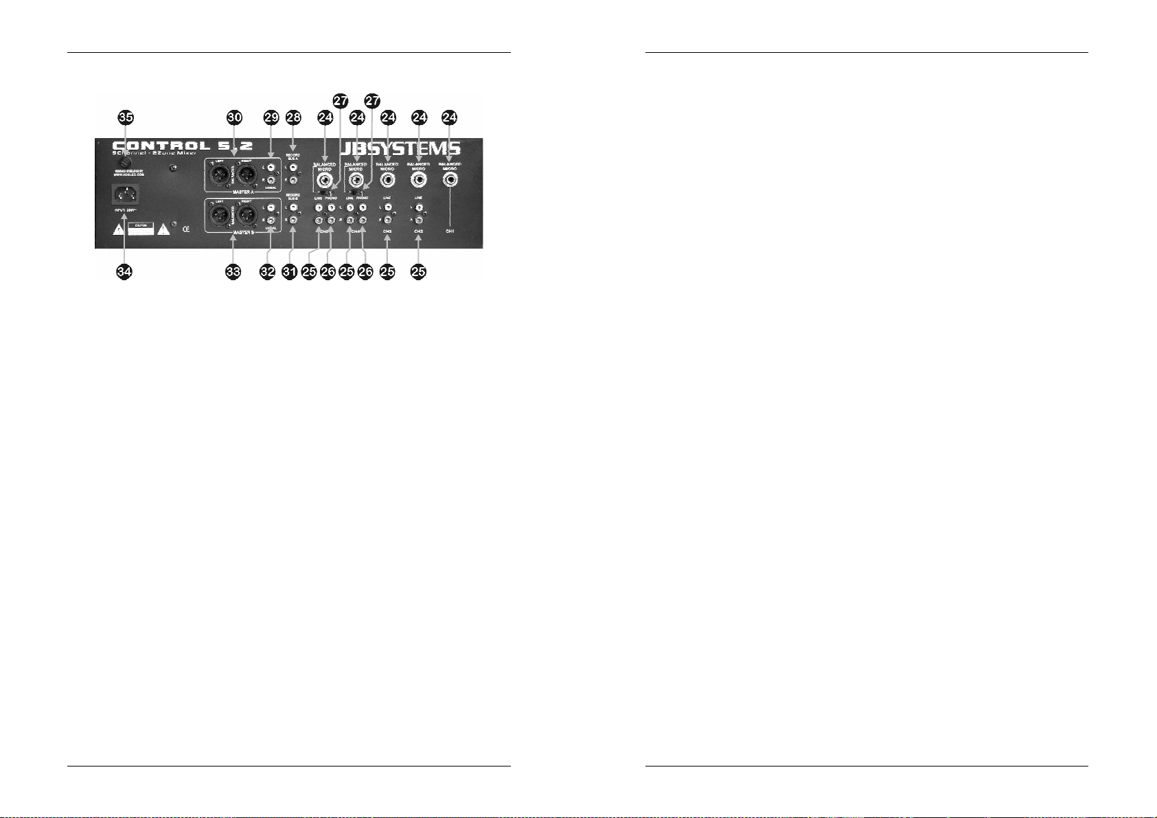
REAR PANEL
24.DJ MICRO input: Used to connect a balanced (stereo jack) or unbalanced (mono
jack) micro to this channel.
25.LINE input: Used to connect any line level sound source to this channel.
26.PHONO input: Used to connect a turntable to this channel.
27.PHONO/LINE switch: Used to select either the phono input(26) or microphone
input(24) on channels 4 and 5.
28.RECORD BUS A: line level output with the signals from channels 2 to 5. Only the
channels where you selected zone A will be on this output.
Important note: the tone controls, DJ microphone and talkover function are NOT available on this
output. This means that the DJ can talk as much as he wants; on this output only the music will be
recorded.
29.MASTER A unbalanced output: Used to connect an amplifier with unbalanced
inputs. The output level can be set by the MASTER A level (18).
30.MASTER A balanced output: Used to connect an amplifier with balanced inputs.
The output level can be set by the MASTER A level (18).
31.RECORD BUS B: line level output with the signals from channels 2 to 5. Only the
channels where you selected zone B will be on this output.
Important note: the tone controls, DJ microphone and talkover function are NOT available on this
output. This means that the DJ can talk as much as he wants; on this output only the music will be
recorded.
32.MASTER B unbalanced output: Used to connect an amplifier with unbalanced
inputs. The output level can be set by the MASTER B level (16).
33.MASTER B balanced output: Used to connect an amplifier with balanced inputs.
The output level can be set by the MASTER B level (16).
34.MAINS INPUT: connect the supplied mains cable to a 230V/50Hz mains outlet.
Before use, inspect the cable to be sure it’s not damaged!
35.MAIN FUSE: The main fuse protects the mixer. Replace it only with the same
type and value.
SPECIFICATIONS
Power Supply: AC 230 V, 50Hz
Fuse: 20mm glass fuse 250V 500mA slow
Frequency response: 20-20.000Hz (+/-2dB)
THD + noise: <0.1% @ 1kHz, 0dB
S/N Ratio (IHF-A): >85dB @ 1kHz.
Micro inputs: 1.5mV @ 10kΩ
Line/CD inputs: 150mV @ 22kΩ
Phono inputs: 3mV @ 47kΩ
Record output: 775mV @ 600Ω
Master A/B output: 1.5V @ 4k7Ω unbal.
Master A/B output: 850mV @ 600Ω bal.
Talkover: 0dB -15dB
Tone controls: +/-12dB @ 10kHz / 1kHz / 100Hz
Headphone: 1V@33Ω
Dimensions: 483(W) x 134(H) x 130(D) mm
Weight: 2kg
JB SYSTEMS® 5/36 CONTROL5.2 / MIX5.2 MIXER
JB SYSTEMS® 6/36 CONTROL5.2 / MIX5.2 MIXER
Page 6
FRANCAIS MODE D'EMPLOI
MODE D'EMPLOI
CARACTERISTIQUES
2 zones indépendantes, chacune avec des sorties XLR balancés (+ non balancés
par connecteurs cinch)
Chaque zone dispose d’un contrôle de tonalité à 3 bandes, d’un réglage de
balance, de volume et d’un sélecteur mono/stéréo
11 entrées sur 5 canaux (5 mic balancés + 4line + 2phono)
1Micro avec contrôle de tonalité à 3 bandes et atténuation (talkover) réglable,
assignable à une zone.
Chaque canal peut être assigné à la zone A, la zone B ou les deux ensemble.
Chaque canal possède des indicateurs Led individuels signalant la présence d’un
signal et les pointes (peak) du niveau.
Réglage Gain et curseur de 45mm sur tous les canaux
PFL avec sélecteur rotatif, réglage de niveau et prise casque jack de 6.3mm.
2 sorties d’enregistrement n’incluant ni le micro du canal 1, ni l’effet d’atténuation
du talkover.
AVANT L'UTILISATION
VÉRIFIER LE CONTENU:
Vérifiez que l'emballage contienne les différents éléments:
Unité de mixage CONTROL5.2 / MIX5.2
Mode d'emploi
Câble d’alimentation
INSTRUCTIONS DE SECURITE:
CAUTION
de l’appareil que vous pouvez remplacer vous-même. Confiez l’entretien
uniquement aux techniciens qualifiés.
La flèche dans un triangle met l'utilisateur en garde de la présence de haut
voltage sans isolation dans l'appareil qui peut causer un risque
d'électrocution.
Un point d'exclamation dans un triangle prévient de la présence
d'instructions de fonctionnement et de maintenance se trouvant dans le
manuel, fourni avec l'appareil.
Ce symbole signifie : uniquement pour usage à l'intérieur
Afin d’éviter tout risque d’incendie ou de choc électrique, ne pas exposer cet
appareil à la pluie ou l’humidité.
Pour éviter la formation de condensation à l’intérieur de l’appareil, patientez
quelques minutes pour laisser l’appareil s’adapter à la température ambiante
lorsqu’il arrive dans une pièce chauffée après le transport. La condensation
ATTENTION: afin de réduire le risque
d’électrocution, n’enlevez jamais le couvercle
de l’appareil. Il n’y a aucune pièce à l’intérieur
FRANCAIS MODE D'EMPLOI
empêche l’unité de fonctionner en performance optimale et peut même causer des
dommages.
Cette unité est destinée à une utilisation à l’intérieur uniquement.
Ne pas insérer d’objet métallique ou verser un liquide dans l’appareil. Aucun objet
rempli de liquides, tels que des vases, ne sera placé sur cet appareil. Risque de
choc électrique ou de dysfonctionnement. Si un corps étranger est introduit dans
l’unité, déconnectez immédiatement de la source d’alimentation.
Aucune source de flamme nue, telle que les bougies allumées, ne devrait être
placée sur l'appareil.
Ne pas couvrir les ouvertures de ventilation, un risque de surchauffe en résulterait.
Ne pas utiliser dans un environnement poussiéreux et nettoyez l’unité
régulièrement.
Ne pas laisser l’unité à portée des enfants.
Les personnes non expérimentées ne doivent pas utiliser cet appareil.
La température ambiante maximum d’utilisation de l’appareil est de 45°C. Ne pas
l’utiliser au-delà de cette température.
Débranchez toujours l’appareil si vous ne l’utilisez pas de manière prolongée ou
avant d’entreprendre des réparations.
Les installations électriques ne peuvent être faites que par du personnel qualifié et
conformément aux régulations de sécurité électrique et mécanique en vigueur dans
votre pays.
Assurez-vous que le voltage de la source d’alimentation de la zone dans laquelle
vous vous trouvez ne dépasse pas celui indiqué à l’arrière de l’appareil.
La prise sera toujours accessible pour que le cordon secteur puisse être enlevé à
chaque moment.
Le cordon d’alimentation doit toujours être en condition parfaite. Mettez
immédiatement l’unité hors tension si le cordon est écrasé ou endommagé.
Ne laissez jamais le cordon d’alimentation entrer en contact avec d’autres câbles !
Utilisez toujours les câbles appropriés et certifiés lorsque vous installez l’unité.
Pour éviter tout choc électrique, ne pas ouvrir l’appareil. En dehors du fusible
principal, il n’y a pas de pièces pouvant être changées par l’utilisateur à l’intérieur.
Ne jamais réparer ou court-circuiter un fusible. Remplacez systématiquement un
fusible endommagé par un fusible de même type et spécifications électriques !
En cas de problèmes de fonctionnement sérieux, arrêtez toute utilisation de
l’appareil et contactez votre revendeur immédiatement.
Utilisez l’emballage d’origine si l’appareil doit être transporté.
Pour des raisons de sécurité, il est interdit d’apporter toute modification à l’unité
non spécifiquement autorisée par les parties responsables.
CONSEILS D'INSTALLATION:
Installer l'appareil dans un lieu bien aéré, à l'abri de l'humidité et des fortes
températures.
Placer et utiliser l'appareil à proximité de sources de chaleur telles que spots,
amplis,… pourrait affecter ses performances et même endommager l'appareil.
L'appareil peut être installé dans un rack 19''. Fixer l'appareil en utilisant les 4 trous
pour vis sur la face avant. Assurez-vous d'utiliser des vis de la bonne dimension
(vis non fournies). Essayez d'éviter les vibrations et les coups lors du transport.
En cas d'installation dans un 'flight case', assurer une bonne ventilation afin
d'évacuer la chaleur produite par l'appareil.
JB SYSTEMS® 7/36 CONTROL5.2 / MIX5.2 MIXER
JB SYSTEMS® 8/36 CONTROL5.2 / MIX5.2 MIXER
Page 7

FRANCAIS MODE D'EMPLOI
FRANCAIS MODE D'EMPLOI
Pour éviter la condensation à l'intérieur, laisser l'appareil s'adapter à la nouvelle
température ambiante après le transport. La condensation peut altérer les
performances de l'appareil.
NETTOYAGE:
Nettoyer en frottant à l'aide d'un chiffon doux très légèrement humide. Eviter de
verser de l'eau dans l'appareil. Ne pas utiliser de liquides abrasifs qui pourraient
endommager l'appareil.
CONNECTIONS
Mis à part pour les micros, les écouteurs et les sorties zones, toutes les connections
sont cinch. Utilisez des câbles cinch/cinch de bonne qualité afin d'éviter un son de
mauvaise qualité. (ex.: JB Systems code: 2-0370)
Pour plus d'informations sur les connections, voyez le chapitre suivant.
Assurez-vous d'éteindre la table de mixage avant d'effectuer les différentes
connections. Dans ce mode d'emploi, il est question d'entrée ligne ou “line inputs”. Il
s'agit en fait d'un terme générique pour désigner des entrées avec un niveau compris
entre 750mV et 2V. Ceci inclus les lecteurs de CD, tuners, vidéos,…
FACE AVANT
1. DJ MICRO input: le micro DJ peut être connecté par l’entrée XLR/Jack situé sur
la face avant ou par le jack stéréo situé à l’arrière de l’appareil. Cette entrée est
balancée mais accepte toutes sortes de micros équipés d’un connecteur XLR ou
Jack.
2. TALKOVER level: Si vous enclenchez le talkover (3), vous pouvez régler le
niveau d’atténuation des canaux 2 à 5. Au plus que vous tournez le bouton vers
la droite, au plus ces canaux seront atténués quand vous parlez dans le micro DJ
(1).
3. TALKOVER: utilisez ce sélecteur si vous voulez atténuer automatiquement les
canaux 2 à 5 pendant que vous parlez dans le micro DJ. Utilisez les sélecteurs de
zone(4) pour choisir la zone dans laquelle le talkover doit agir.
Attention: le talkover agira uniquement dans la zone que vous avez sélectionné pour le micro DJ.
L’autre zone ne sera pas affectée.
4. interrupteur de ZONE: pour chaque canal d’entrée vous pouvez choisir vers
quelle zone (master) il doit être conduit. Ceci vous permet d’utiliser cette table de
mixage pour pourvoir deux différentes salles d’une musique complètement
différente!
Exemple:
Vous voulez que les canaux 2&3 soient conduits vers le Master A (salle1). Les
canaux 4&5 doivent être conduits vers le Master B (salle2). Mais vous voulez
avoir la possibilité de faire des annonces dans les deux salles. Voici ce que
vous devez faire:
Sélectionnez “zone A” pour les canaux 2&3
sélectionnez “zone B” pour les canaux 4&5
sélectionnez “zone A” et “zone B” pour l’entrée micro DJ Micro.
Vous pouvez maintenant faire des annonces simultanément dans les deux
salles, pendant que la musique que vous jouez dans les deux salles est
complètement différente.
5. Sélecteur INPUT: Pour les canaux 2 et 3 vous pouvez choisir entre les entrées
Line ou entrées micros balancés.
6. Sélecteur INPUT: Pour les canaux 4 et 5 vous pouvez choisir entre les entrées
Line ou entrées micros balancés, mais vous pouvez également connecter une
platine vinyle. (sélecteur line/phono à l’arrière de l’appareil)
7. Sélecteur MONO/STEREO: est utilisé pour mettre le Master A en mono ou en
stéréo.
8. BALANCE: est utilisé pour régler la balance entre la sortie gauche et droite du
Master A.
9. VU-mètres: sont utilisés pour visualiser le niveau du signal audio, sélectionné
avec le sélecteur CUE (13). Avec les curseurs des canaux vous pouvez changer
le niveau d’entrée de chaque source audio qui est connectée. Faites attention de
ne pas dépasser 0dB (ou 100%). Une distorsion du signal audio peut se produire
si son niveau entre dans la zone rouge du VU-mètre.
10.Sélecteur MONO/STEREO: est utilisé pour mettre le Master B en mono ou en
stéréo.
11.BALANCE: est utilisé pour régler la balance entre la sortie gauche et droite du
Master B.
12.Interrupteur POWER: est utilisé pour allumer ou éteindre la table de mixage.
13.Sélecteur CUE: est utilisé pour sélectionner la source que vous voulez pré
écouter. Vous pouvez pré écouter chaque canal d’entrée pendant que le curseur
du canal est fermé.
14.CUE LEVEL: est utilisé pour régler le niveau de la sortie casque.
15.HEADPHONE jack: vous pouvez raccorder n’importe quel casque stéréo
moderne à cette entrée jack de 6.3mm. Avec le sélecteur Cue (13) et le réglage
de niveau Cue Level(14) vous pouvez pré écouter la source d’entrée
sélectionnée.
16.MASTER B level: est utilisé pour régler le niveau de sortie du Master B.
17.Réglage de TONALITÉ à 3 bandes: utilisez ces 3 contrôleurs pour modifier le
signal audio du Master B selon votre goût personnel.
18.MASTER A level: est utilisé pour régler le niveau de sortie du Master A.
19.Réglage de TONALITÉ à 3 bandes: utilisez ces 3 contrôleurs pour modifier le
signal audio du Master A selon votre goût personnel.
JB SYSTEMS® 9/36 CONTROL5.2 / MIX5.2 MIXER
JB SYSTEMS® 10/36 CONTROL5.2 / MIX5.2 MIXER
Page 8

FRANCAIS MODE D'EMPLOI
FRANCAIS MODE D'EMPLOI
20.GAIN: utilisez ce contrôleur pour régler la sensibilité de chaque canal
séparément. Basez-vous sur les informations des VU mètres (9) et du « peak
led » (22) pour bien régler la sensibilité du canal.
21.CURSEURS / CANAL: utilisez-les pour régler le niveau de chaque canal.
22.PEAK & SIGNAL LEDS: tous les canaux sont équipés d’un « peak led » et d’un
« signal led »:
Signal led: Le led vert indique la présence d’un signal audio à l’entrée du
canal.
Peak led: le led rouge « peak » indique que le signal d’entrée est trop élevé.
Assurez-vous que le « peak led » ne s’allume que de temps en temps. Si ce led
reste allumé pendant de longues périodes vous devez absolument diminuer le
signal d’entrée en utilisant le contrôleur GAIN (20) du canal approprié.
23.Réglage de TONALITÉ à 3 bandes: vous pouvez utiliser ces 3 contrôleurs pour
modifier le signal audio du micro DJ selon votre goût personnel ou pour enlever
l’effet Larsen du micro.
Remarque: L’effet Larsen se produit lors-ce qu’un signal acoustique est amplifié et ré amplifié
jusqu’à-ce qu’il se transforme en un bruit strident continu: diminuez le Gain de votre canal micro
et/ou essayez de couper les hautes fréquences avec le contrôle de tonalité.
FACE ARRIERE
24.DJ MICRO input: est utilisé pour connecter un micro balancé (jack stéréo) ou un
micro non balancé (jack mono).
25.LINE input: est utilisé pour connecter n’importe quelle source sonore du type
« Line ».
26.PHONO input: est utilisé pour connecter une platine vinyle.
27.Interrupteur PHONO/LINE: est utilisé pour sélectionner soit l’entrée phono (26),
soit l’entrée micro (24) pour les canaux 4 et 5.
28.RECORD BUS A: sortie « line » du signal des canaux 2 à 5. Cette sortie ne
reproduira que les canaux que vous avez sélectionnés pour la zone A.
Remarque importante: les contrôles de tonalité, le micro DJ et la fonction talkover ne sont PAS
disponibles sur cette sortie. Ce qui veut dire que le DJ peut parler autant qu’il veut ; par cette
sortie vous n ’enregistrerez que la musique.
29.MASTER A sortie non balancée: est utilisé pour connecter un amplificateur qui
est pourvu d’entrées non balancés. Le niveau de sortie peut être réglé avec le
contrôleur de niveau du MASTER A (18).
30.sortie balancée MASTER A: est utilisé pour connecter un amplificateur qui est
pourvu d’entrées balancés. Le niveau de sortie peut être réglé avec le contrôleur
de niveau du MASTER A (18).
31.RECORD BUS B: sortie « line » du signal des canaux 2 à 5. Cette sortie ne
reproduira que les canaux que vous avez sélectionnés pour la zone B.
Remarque importante: les contrôles de tonalité, le micro DJ et la fonction talkover ne sont PAS
disponibles sur cette sortie. Ce qui veut dire que le DJ peut parler autant qu’il veut ; par cette
sortie vous n ’enregistrerez que la musique.
32.MASTER B sortie non balancée: est utilisé pour connecter un amplificateur qui
est pourvu d’entrées non balancés. Le niveau de sortie peut être réglé avec le
contrôleur de niveau du MASTER B (16).
33.sortie balancée MASTER B: est utilisé pour connecter un amplificateur qui est
pourvu d’entrées balancés. Le niveau de sortie peut être réglé avec le contrôleur
de niveau du MASTER B (16).
34.MAINS INPUT: connectez le câble d’alimentation qui est fourni avec l’appareil au
secteur 230V/50Hz. Vérifiez d’abord si le câble n’est pas endommagé!
35.MAIN FUSE: Le fusible d’alimentation protège la table de mixage. Remplacez-le
uniquement par un fusible du même type et de la même valeur.
CARACTERISTIQUES TECHNIQUES
Alimentation: AC 230 V, 50Hz
Fusible: 20mm en verre 250V 500mA lent
Réponse de fréquence: 20-20.000Hz (+/-2dB)
DHT + bruit: <0.1% @ 1kHz, 0dB
S/N Ratio (IHF-A): >85dB @ 1kHz.
Entrées micro: 1.5mV @ 10kΩ
Entrées Line/CD: 150mV @ 22kΩ
Entrées Phono: 3mV @ 47kΩ
Sortie Record: 775mV @ 600Ω
Sortie Master A/B: 1.5V @ 4k7Ω non bal.
Sortie Master A/B: 850mV @ 600Ω bal.
Talkover: 0dB -15dB
Contrôle de tonalité: +/-12dB @ 10kHz / 1kHz / 100Hz
Casque: 1V@33Ω
Dimensions: 483(W) x 134(H) x 130(D) mm
Poids: 2kg
JB SYSTEMS® 11/36 CONTROL5.2 / MIX5.2 MIXER
JB SYSTEMS® 12/36 CONTROL5.2 / MIX5.2 MIXER
Page 9

NEDERLANDS GEBRUIKSAANWIJZING
GEBRUIKSAANWIJZING
KENMERKEN
2 onafhankelijke Zones, elk met een gebalanceerde XLR uitgang, alsook een
ongebalanceerde cinch uitgang.
Elke zone heeft een 3-bands toonregeling, balans, volume en mono/stereo
schakelaar.
11 ingangen op 5 kanalen (5 gebalanceerde mic + 4line + 2phono)
1microfoon met 3-bands toonregeling en een regelbare talkover die aan een zone
kan toegewezen worden.
Elk kanaal kan aan zone A, zone B of aan beide toegewezen worden.
Elk kanaal heeft individuele peak en signaal leds.
Gain niveauregeling en 45mm schuifregelaars op alle kanalen
PFL met keuzeschakelaar, cue niveauregeling en 6.3mm koptelefoon jack.
2 onafhankelijke record uitgangen zonder kanaal1 microfoon en vrij van talkover
demping.
VOOR GEBRUIK
Controleer de inhoud:
Kijk na of de doos volgende producten bevat:
CONTROL5.2 / MIX5.2 Mixer
Handleiding
Stroomkabel
VEILIGHEIDSVOORSCHRIFTEN:
CAUTION
Voor reparaties doet U best uitsluitend beroep op degelijk opgeleid
personeel.
De driehoek met bliksem symbool waarschuwt U dat er in dit apparaat
ongeïsoleerde spanning aanwezig is die bij aanraking een elektrische schok
kan veroorzaken.
De driehoek voorzien van een uitroepteken waarschuwt U dat er belangrijke
gebruikersinstructies in de bijbehorende handleiding te vinden zijn.
OPGELET: Gelieve, om het risico op
elektrische schokken te vermijden, het
apparaat niet zelf te openen. Binnenin vindt U
geen onderdelen die U zelf kan vervangen.
NEDERLANDS GEBRUIKSAANWIJZING
vertrek is overgebracht. Condensatie kan het toestel soms verhinderen perfect te
functioneren. Het kan soms zelfs schade aan het apparaat toebrengen.
Gebruik dit apparaat uitsluitend binnenshuis.
Plaats geen stukken metaal en mors geen vocht binnen in het toestel om
elektrische schokken of storing te vermijden. Objecten gevuld met water, zoals
bvb. Vazen, mogen op dit apparaat worden geplaatst. Indien er toch een vreemd
voorwerp of water in het apparaat geraakt, moet U het direct van het lichtnet
afkoppelen.
Open vuur, zoals brandende kaarsen, mogen niet op het apparaat geplaatst
worden.
Bedek geen enkele ventilatieopening om oververhitting te vermijden.
Zorg dat het toestel niet in een stoffige omgeving wordt gebruikt en maak het
regelmatig schoon.
Houd het apparaat uit de buurt van kinderen.
Dit apparaat mag niet door onervaren personen bediend worden.
De maximum veilige omgevingstemperatuur is 45°C. Gebruik het apparaat dus niet
bij hogere temperaturen.
Trek altijd de stekker uit wanneer het apparaat gedurende langere tijd niet wordt
gebruikt of alvorens met de onderhoudsbeurt te beginnen.
De elektrische installatie behoort uitsluitend uitgevoerd te worden door bevoegd
personeel, volgens de in uw land geldende regels betreffende elektrische en
mechanische veiligheid.
Controleer dat de beschikbare spanning niet hoger is dan die aangegeven op de
achterzijde van het toestel.
Het stopcontact zal steeds vrij toegankelijk blijven zodat de stroomkabel op elk
moment kan worden uitgetrokken.
De elektrische kabel behoort altijd in uitstekende staat te zijn. Zet het apparaat
onmiddellijk af als de elektrische kabel gekneusd of beschadigd is.
Laat de elektrische draad nooit in contact komen met andere draden.
Volgens de veiligheidsvoorschriften moet deze installatie geaard worden.
Om elektrische schokken te voorkomen, moet U de behuizing niet openen.
Afgezien van de zekering zitten er geen onderdelen in die door de gebruiker
moeten worden onderhouden.
Repareer nooit een zekering en overbrug de zekeringhouder nooit. Vervang een
beschadigde zekering steeds door een zekering van hetzelfde type en met
dezelfde elektrische kenmerken.
Ingeval van ernstige problemen met het bedienen van het toestel, stopt U
onmiddellijk het gebruik ervan. Contacteer uw dealer voor een eventuele reparatie.
Gebruik best de originele verpakking als het toestel vervoerd moet worden.
Om veiligheidsredenen is het verboden om ongeautoriseerde modificaties aan het
toestel aan te brengen.
Dit symbool betekent: het apparaat mag enkel binnenhuis worden gebruikt.
Stel dit apparaat niet bloot aan regen of vocht, dit om het risico op brand en
elektrische schokken te voorkomen.
Om de vorming van condensatie binnenin te voorkomen, laat het apparaat aan de
omgevingstemperatuur wennen wanneer het, na het transport, naar een warm
JB SYSTEMS® 13/36 CONTROL5.2 / MIX5.2 MIXER
INSTALLATIEVOORSCHRIFTEN:
Plaats de mengtafel in een goed geventileerde ruimte waar zij niet blootgesteld is
aan hoge temperaturen of vocht.
Het plaatsen en het gebruik van de mengtafel gedurende een lange periode in de
nabijheid warmtebronnen zoals versterkers, spots, enz. zal zijn werking
beïnvloeden.
JB SYSTEMS® 14/36 CONTROL5.2 / MIX5.2 MIXER
Page 10

NEDERLANDS GEBRUIKSAANWIJZING
NEDERLANDS GEBRUIKSAANWIJZING
De mixer kan in een 19” kast gemonteerd worden. Monteer de behuizing door
middel van de 4 montageopeningen op de frontplaat. Gebruik hiervoor bouten van
de juiste dikte! (deze zijn niet inbegrepen) Probeer sterke schokken en vibraties
tijdens het transport zo veel mogelijk te vermijden.
Zorg, bij inbouw in een vaste installatie of flightcase, voor een goede ventilatie om
de warmte optimaal te kunnen afvoeren.
Zorg ervoor, om inwendige vorming van condensatie te voorkomen, dat de
mengtafel zich na transport kan aanpassen aan de warme binnentemperatuur.
Condensatie kan de goede werking soms verhinderen.
REINIGING VAN DE MENGTAFEL:
Reinig de mengtafel met een vochtig doek. Vermijd dat er water in het toestel komt.
Gebruik nooit vluchtige vloeistoffen zoals benzeen of thinner welke het toestel
kunnen beschadigen.
AANSLUITINGEN
Behalve de microfoon-, hoofdtelefoonaansluitingen en zone uitgangen, zijn alle
aansluitingen cinch-aansluitingen. Gebruik cinch-cinch kabels van goede kwaliteit om
een goede geluidskwaliteit te verzekeren. (Bijvoorbeeld: JB Systems code :2-0370)
Voor meer informatie over aansluitingen verwijzen wij u naar het volgende hoofdstuk.
Zet het toestel uit, vooraleer u verandering aanbrengt bij de bekabeling. In deze
handleiding spreken we over lijn-ingangen. Dit is een globale naam voor ingangen
met een niveau tussen 750mV en 2V. Deze ingangen vindt u bijvoorbeeld bij radio’s,
video’s, cd-spelers, enz.
FRONT
1. DJ MICRO input: de DJ microfoon kan aangesloten worden via de XLR/Jack
ingang op de frontplaat of via de stereo jack aansluiting op de achterzijde van de
mengtafel. Dit is een gebalanceerde ingang maar aanvaard om het even welke
microfoon, voorzien van een XLR of jack aansluiting.
2. TALKOVER level: wanneer u de talkover schakelaar(3) aanzet, kunt u de
demping van de kanalen 2 tot 5 instellen. Hoe meer u de knop naar rechts draait,
hoe meer deze kanalen gedempt worden terwijl u in de DJ Microfoon(1) praat.
3. TALKOVER schakelaar: gebruik deze schakelaar om de kanalen 2 tot 5
automatisch te dempen terwijl u in de DJ microfoon praat. Gebruik de zone
keuzeschakelaars(4) om te bepalen op welke uitgang de talkover moet werken.
Opgelet: de talkover zal enkel werken op de zone die u ingesteld heeft voor de DJ Microfoon. De
andere zone zal niet beïnvloed worden.
4. ZONE schakelaar: voor elk kanaal kunt u kiezen naar welke zone (master) het
signaal moet geleid worden. Dit betekent dat u de mengtafel kunt gebruiken om
twee verschillende zalen te voorzien van een totaal verschillende muziek!
Voorbeeld:
U wilt de kanalen 2&3 sturen naar Master A (zaal1). De kanalen 4&5 moeten
gestuurd worden naar Master B (zaal2). Maar u wilt aankondigingen kunnen
maken in beide zalen samen.
Dit is wat u zou moeten doen:
kies “zone A” voor de kanalen 2&3
kies “zone B” voor de kanalen 4&5
kies “zone A” en “zone B” voor de DJ Microfoon.
U kunt nu aankondigingen maken in beide zalen samen, terwijl de muziek die
u in beide zalen speelt volledig verschillend is.
5. INPUT SELECTOR schakelaar: voor de kanalen 2 en 3 kunt u kiezen tussen line
ingangen of gebalanceerde microfoon ingangen.
6. INPUT SELECTOR schakelaar: voor de kanalen 4 en 5 kunt u kiezen tussen line
ingangen of gebalanceerde microfoon ingangen maar u kunt ook een draaitafel
aansluiten. (line/phono schakelaar op de achterzijde)
7. MONO/STEREO schakelaar: wordt gebruikt om Master A in mono of stereo om
te zetten.
8. BALANCE: wordt gebruikt om de balans tussen de linker en rechter uitgang van
Master A te regelen.
9. VU-meter: wordt gebruikt om het niveau van de geluidssignalen te controleren
die met de CUE schakelaar(13) gekozen werden. Met de kanaalschuifregelaars
kunt u het ingangsniveau van elke aangesloten geluidsbron regelen. Zorg ervoor
dat de niveaus de 0dB (of 100%) niet overschrijden. Dit kan distorsie van het
geluidssignaal veroorzaken wanneer het niveau in de rode zone van de VU-meter
komt.
10.MONO/STEREO schakelaar: wordt gebruikt om Master B in mono of stereo om
te zetten.
11.BALANCE: wordt gebruikt om de balans tussen de linker en rechter uitgang van
Master B te regelen.
12.POWER schakelaar: wordt gebruikt om de voeding van de mengtafel aan of uit
te zetten.
13.CUE schakelaar: wordt gebruikt om de bron te kiezen die u wilt voorbeluisteren.
U kunt naar om het even welk kanaal luisteren terwijl de schuifregelaar van dat
kanaal gesloten is.
14.CUE LEVEL: wordt gebruikt om het uitgangsniveau van de koptelefoon te
regelen.
15.HEADPHONE jack: u kunt om het even welke moderne stereo hoofdtelefoon
aansluiten via deze 6.3mm jack. Samen met de cue keuzeschakelaar (13) en de
cue niveauregeling (14) kunt u deze gebruiken om het gekozen ingangskanaal
voor te beluisteren.
16.MASTER B level: wordt gebruikt om het uitgangsniveau van Master B te regelen.
17.3-BANDS TOONREGELING: gebruik deze 3-bands toonregeling om het
geluidssignaal van Master B aan te passen volgens uw persoonlijke smaak.
JB SYSTEMS® 15/36 CONTROL5.2 / MIX5.2 MIXER
JB SYSTEMS® 16/36 CONTROL5.2 / MIX5.2 MIXER
Page 11

NEDERLANDS GEBRUIKSAANWIJZING
NEDERLANDS GEBRUIKSAANWIJZING
18.MASTER A level: wordt gebruikt om het uitgangsniveau van Master A te regelen.
19.3-BANDS TOONREGELING: gebruik deze 3-bands toonregeling om het
geluidssignaal van Master A aan te passen volgens uw persoonlijke smaak.
20.GAIN controles: worden gebruikt om de gevoeligheid van elk kanaal apart te
regelen. U kunt de gevoeligheid van de kanalen regelen, gebaseerd op de
informatie van de VU meters(9) en de peak led(22).
21.KANAAL SCHUIFREGELAARS: worden gebruikt om het niveau van elk kanaal
afzonderlijk in te stellen.
22.PEAK & SIGNAL LEDS: alle kanalen zijn uitgerust met een peak een signaal led:
Signal led: de groene signaalled geeft aan dat er een muzieksignaal aanwezig
is op de kanaalingang.
Peak led: de rode peak led geeft aan dat het ingangssignaal te hoog is. Let er
op dat de peak led slechts af en toe aan gaat. Wanneer de peak led gedurende
langere periodes aan blijft, moet u dringend het niveau van het ingangssignaal
verminderen door middel van de GAIN regeling(20).
23.3-BANDS TOONREGELING: u kunt deze 3 regelingen gebruiken om het
geluidssignaal of de DJ microfoon te regelen volgens uw persoonlijke smaak of
om feedback van de microfoon weg te filteren.
Opmerking: Feedback is wanneer een akoestisch signaal steeds weer versterkt wordt tot het snel
in een luide schreeuw overgaat: verminder de gain van uw microfoonkanaal en/of probeer de HF
te verminderen van uw toonregeling.
ACHTERZIJDE
24.DJ MICRO input: wordt gebruikt om gebalanceerde (stereo jack) of
ongebalanceerde (mono jack) microfoons aan te sluiten op dit kanaal.
25.LINE input: wordt gebruikt om het even welke geluidsbron met een line niveau
op dit kanaal aan te sluiten.
26.PHONO input: wordt gebruikt om een draaitafel op dit kanaal aan te sluiten.
27.PHONO/LINE schakelaar: wordt gebruikt om ofwel de phono (draaitafel)
ingang(26) ofwel de microfooningang(24) te kiezen voor de kanalen 4 en 5.
28.RECORD BUS A: line uitgang met de signalen van de kanalen 2 tot 5. Enkel de
kanalen welke u koos voor de zone A zullen door deze uitgang gestuurd worden.
Belangrijke opmerking: de toonregeling, DJ microfoon en talkover functie hebben GEEN invloed
op deze uitgang. Dit betekent dat de DJ zo veel kan praten als hij wil; via deze uitgang zal alleen
de muziek opgenomen worden.
29.MASTER A ongebalanceerde uitgang: wordt gebruikt om een versterker aan te
sluiten die uitgerust is met ongebalanceerde ingangen. Het uitgangsniveau kan
geregeld worden met de MASTER A niveauregelaar (18).
30.MASTER A gebalanceerde uitgang: wordt gebruikt om een versterker aan te
sluiten die uitgerust is met gebalanceerde ingangen. Het uitgangsniveau kan
geregeld worden met de MASTER A niveauregelaar (18).
31.RECORD BUS B: line uitgang met de signalen van de kanalen 2 tot 5. Enkel de
kanalen welke u koos voor de zone B zullen door deze uitgang gestuurd worden.
Belangrijke opmerking: de toonregeling, DJ microfoon en talkover functie hebben GEEN invloed
op deze uitgang. Dit betekent dat de DJ zo veel kan praten als hij wil; via deze uitgang zal alleen
de muziek opgenomen worden.
32.MASTER B ongebalanceerde uitgang: wordt gebruikt om een versterker aan te
sluiten die uitgerust is met ongebalanceerde ingangen. Het uitgangsniveau kan
geregeld worden met de MASTER B niveauregelaar (16).
33.MASTER B gebalanceerde uitgang: wordt gebruikt om een versterker aan te
sluiten die uitgerust is met gebalanceerde ingangen. Het uitgangsniveau kan
geregeld worden met de MASTER B niveauregelaar (16).
34.MAINS INPUT: verbind hier de meegeleverde voedingskabel met het 230V/50Hz
net. Controleer eerst of de kabel niet beschadigd is!
35.HOOFDZEKERING: De hoofdzekering beschermt de mengtafel. Vervang hem
enkel door een zekering van het zelfde type en waarde.
SPECIFICATIES
Voeding: AC 230 V, 50Hz
Zekering: 20mm glazen zekering 250V 500mA traag
Frequentie bereik: 20-20.000Hz (+/-2dB)
Vervorming + ruis: <0.1% @ 1kHz, 0dB
S/R verhouding (IHF-A): >85dB @ 1kHz.
Microfoon ingangen: 1.5mV @ 10kΩ
Line/CD ingangen: 150mV @ 22kΩ
Phono ingangen: 3mV @ 47kΩ
Record uitgang: 775mV @ 600Ω
Master A/B uitgang: 1.5V @ 4k7Ω ongebal.
Master A/B uitgang: 850mV @ 600Ω gebal.
Talkover: 0dB -15dB
Tooncontrole: +/-12dB @ 10kHz / 1kHz / 100Hz
Koptelefoon: 1V@33Ω
Afmetingen: 483(W) x 134(H) x 130(D) mm
Gewicht: 2kg
JB SYSTEMS® 17/36 CONTROL5.2 / MIX5.2 MIXER
JB SYSTEMS® 18/36 CONTROL5.2 / MIX5.2 MIXER
Page 12

DEUTSCH BEDIENUNGS ANLEITUNG
BEDIENUNGSANLEITUNG
EIGENSCHAFTEN
2 unabhängige Zonen, jede mit symmetrischen XLR Ausgängen (und
unsymmetrische über Chinch)
Jede Zone besitzt eine 3-fach Klangeinstellung, Balance, Lautstärke und
Mono/Stereo Schalter
11 Eingänge auf 5 Kanälen (5 Mikrofon + 4 Line + 2 Phono)
1 Mikrofon mit 3-fach Klangeinstellung, Zonenzuweisung und einstellbaren
Talkover.
Jeder Kanal kann auf Zone A, Zone B oder beiden geroutet werden.
Jeder Kanal hat eine eigene Peak- und Signal LED.
Gain Einsteller und 45mm Fader auf allen Kanälen.
PFL mit Wahlschalter, Lautstärkeeinsteller und 6.3mm Kopfhörerbuchse.
2 unabhängige Record Ausgänge ohne Kanal1 Mikrofon und frei von der
Talkoverabsenkung.
VOR DEM GEBRAUCH
KONTROLLE DER VOLLSTÄNDIGKEIT:
Folgende Teile müssen sich in der Geräteverpackung befinden:
CONTROL5.2 / MIX5.2 Mixer
Bedienungsanleitung
Anschlusskabel
SICHERHEITSVORSCHRIFTEN:
CAUTION
reparierbaren Teile. Überlassen Sie Reparaturen dem qualifizierten
Kundendienst.
Das Blitzsymbol im Dreieck weist den Benutzer darauf hin, das eine
Berührungsgefahr mit nicht isolierten Teilen im Geräteinneren, welche eine
gefährliche Spannung führen, besteht. Die Spannung ist so hoch, das hier
die Gefahr eines elektrischen Schlages besteht.
Das Ausrufezeichen im Dreieck weist den Benutzer auf wichtige
Bedienungs- und Wartungshinweise in den Dokumenten hin, die dem Gerät
beiliegen.
Dieses Symbol bedeutet: Nur innerhalb von Räumen verwenden.
Zur Vermeidung von Stromschlag oder Feuer, Gerät bitte nicht Regen oder
Feuchtigkeit aussetzen.
Zur Vermeidung von Kondensation im Inneren des Geräts, bitte nach Transport in
eine warme Umgebung einige Zeit zum Temperaturausgleich bringen.
ACHTUNG: Um sich nicht der Gefahr eines
elektrischen Schlags auszusetzen, entfernen
Sie keines der Gehäuseteile. Im Geräteinneren befinden sich keine vom Benutzer
DEUTSCH BEDIENUNGS ANLEITUNG
Kondensation kann zu Leistungsverlust des Gerätes oder gar Beschädigung
führen.
Gerät nicht im Freien und in feuchten Räumen und Umgebungen verwenden.
Keine Metallgegenstände oder Flüssigkeiten ins Innere des Geräts gelangen
lassen. Keine mit Flüssigkeit gefüllte Gegenstände z.B. Vasen, auf das Gerät
stellen. Kurzschluß oder Fehlfunktion können die Folge sein. Falls es doch einmal
vorkommen sollte, bitte sofort Netzstecker ziehen und vom Stromkreis trennen.
Offene Brandquellen, wie z.B. brennende Kerzen, sollten nicht auf das Gerät
gestellt werden.
Ventilationsöffnungen nicht abdecken, da Überhitzungsgefahr!
Nicht in staubiger Umgebung verwenden und regelmäßig reinigen.
Für Kinder unerreichbar aufbewahren.
Unerfahrene Personen sollen das Gerät nicht bedienen.
Umgebungstemperatur darf 45ºC nicht überschreiten.
Stets Netzstecker ziehen, wenn Gerät für längeren Zeitraum nicht genutzt, oder es
gewartet wird.
Elektrische Anschlüsse nur durch qualifiziertes Fachpersonal überprüfen lassen.
Sicherstellen, daß Netzspannung mit Geräteaufkleber übereinstimmt.
Die Netzsteckdose sollte immer gut erreichbar sein um das Gerät vom Netz zu
trennen.
Gerät nicht mit beschädigtem Netzkabel betreiben.
Netzkabel nicht mit anderen Kabeln in Berührung kommen lassen!
Ausschließlich vorschriftsmäßige Kabel zur Installation verwenden.
Gerät nicht öffnen. Abgesehen vom tausch der Sicherung sind keine zu wartenden
Bauteile im Gerät enthalten.
Sicherung niemals reparieren oder überbrücken, sondern immer mit gleichartiger
Sicherung ersetzen!
Bei Fehlfunktion, Gerät nicht benutzen und mit Händler in Verbindung setzen.
Bei Transport bitte Originalverpackung verwenden, um Schäden am Gerät zu
vermeiden.
Aus Sicherheitsgründen dürfen an dem Gerät keine unbefugten Veränderungen
vorgenommen werden.
INSTALLATIONSANLEITUNG:
Stellen Sie das Mischpult in einem gut belüfteten Raum auf, wo es nicht
Feuchtigkeit und hohen Temperaturen ausgesetzt wird.
Plazieren und benutzen Sie das Mischpult für eine längere Zeit neben sehr warmen
Geräten wie Verstärker, Lampen, etc., könnte es die Funktion des Gerätes
beeinträchtigen.
Das Gerät kann in 19“ Racks eingebaut werden. Benutzen Sie dafür die in der
Frontblende eingelassenen Löcher.
Sollte das Gerät in ein Flightcase eingebaut werden, achten Sie auf eine gute
Luftzirkulation.
Wenn das Mischpult aus einer kalten Umgebung an einem warmen Ort aufgestellt
wird, kann sich Kondenswasser bilden. Um Fehlfunktionen zu vermeiden, sollten
Sie das Gerät für ca. 1 Stunde vom Stromnetz trennen.
JB SYSTEMS® 19/36 CONTROL5.2 / MIX5.2 MIXER
JB SYSTEMS® 20/36 CONTROL5.2 / MIX5.2 MIXER
Page 13

DEUTSCH BEDIENUNGS ANLEITUNG
DEUTSCH BEDIENUNGS ANLEITUNG
REINIGEN DES MISCHPULTES:
Entfernen Sie Staub und Schmutz mit einem weichen, trockenen Tuch. Achten Sie
darauf, dass keine Flüssigkeit in das Geräteinnere gelangen kann. Benutzen Sie
keinen Verdünner, Benzin oder andere chemische Mittel für das Mischpult. Die
Oberfläche des Gerätes könnte zerstört werden.
ANSCHLÜSSE
Außer für Mikrofon, Kopfhörer und den 2 symmetrischen Zonen Ausgängen sind alle
Anschlüsse in Chinch ausgelegt. Verwenden Sie hochwertige Chinch – Chinch Kabel
um eine bessere Klangqualität zu erreichen. ( z.B.: JB SYSTEMS CODE 2-0370):
Für weitere Informationen über die Anschlüsse lesen sie das nächste Kapitel.
Vergewissern Sie sich das dass Gerät ausgeschaltet ist bevor sie Änderungen an
der Verkabelung vornehmen. In dieser Anleitung schreiben wir über „ Line
Eingänge“, das sind Eingänge die zwischen 750 mV und 2V liegen. Das beinhaltet
Tuner, Video, CD Player usw.
VORDER ANSICHT
1. DJ MIKROFON Eingang: Das DJ Mikrofon kann auf der Frontblende über die
XLR/Klinke Kombibuchse oder auf der Rückseite angeschlossen werden. Dieser
Eingang ist symmetrisch. Es kann aber auch jedes andere Mikrofon mit einem
XLR oder Klinkenstecker angeschlossen werden.
2. TALKOVER Pegel: Sollten Sie den Talkover Schalter (3) gedrückt haben,
können Sie mit diesem Einsteller die Absenkung der Eingangskanäle 2 bis 5
einstellen. Je mehr Sie den Knopf nach rechts drehen, umso leiser wird das
Signal beim Reinsprechen in das DJ Mikrofon (1).
3. TALKOVER Schalter: Aktivieren der Talkover Automatik für die Kanäle 2 bis 5.
Stellen Sie mit dem Zonen Wahlschalter (4) ein, auf welcher Zone der Talkover
arbeiten soll.
Achtung: Der Talkover arbeitet nur auf der gewählten Zone des DJ Mikrofon. Die andere Zone
bleibt davon unbeeinflusst.
4. ZONEN Wahlschalter: Für jeden Eingangskanal steht ein Zonenwahlschalter zur
Verfügung. Das bedeutet, das Sie mit diesem Mischpult zwei verschiedene
Räume mit unterschiedlicher Musik versorgen können!
Beispiel:
Sie benötigen Kanal 2&3 auf Master A (Raum1). Und Kanal 4&5 wird auf
Master B (Raum 2) benötigt. Außerdem möchten Sie in beiden Räumen
Ansagen machen. Das müssen Sie tun:
Wählen Sie “Zone A” auf Kanal 2&3
Wählen Sie “Zone B” auf Kanal 4&5
Wählen Sie “Zone A” und “Zone B” am DJ Mikrofon Eingang.
Nun können Sie in beiden Räumen Ansagen machen, während die Musik die
sie spielen komplett verschieden ist..
5. EINGANGS Wahlschalter: Auf den Kanälen 2 & 3 können Sie zwischen LINE
und Mikrofon Signal wählen..
6. EINGANGS Wahlschalter: Auf den Kanälen 4 & 5 können Sie zwischen LINE
und Mikrofon Signal wählen. Hier können Sie auch einen Plattenspieler
anschließen. (Line/Phono Schalter auf der Rückseite)
7. MONO/STEREO Schalter: Mono/Stereo Umschalter für Master A.
8. BALANCE: Links/Rechts Pegel für Master A.
9. AUSSTEUERUNGSANZEIGE: Benutzen Sie dieses Anzeigeinstrument zum
Einstellen der Lautstärke mit dem CUE Schalter (13). Mit den Kanal Fadern
können Sie die Lautstärke jeder angeschlossenen Audio-Quelle einstellen.
Achten Sie darauf das das Signal nicht 0dB (oder 100%) beträgt. Wenn der Pegel
im roten Bereich der Aussteuerungsanzeige ist, verzerrt das Ausgangssignal!
10.MONO/STEREO Schalter: Mono/Stereo Umschalter für Master B.
11.BALANCE: Links/Rechts Pegel für Master B.
12.POWER Schalter: Netzschalter um das Mischpult ein- und auszuschalten.
13.CUE Wahlschalter: Wahlschalter zum Anwählen des Vorhörsignals. Obwohl die
Kanalfader geschlossen sind, können Sie jedes Signal vorhören.
14.CUE LEVEL: Einstellen der Kopfhörerlautstärke.
15.KOPFHÖRERBUCHSE: Hier können Sie einen Stereo Kopfhörer mit einem
6,3mm Stereo Klinkenstecker anschließen. Zusammen mit dem CUE
Wahlschalter (13) und dem CUE Level (14) können Sie das gewünschte Signal
bequem vorhören.
16.MASTER B Lautstärke: Einstellen der Gesamtlautstärke des MASTER B.
17.3-FACH KLANGEINSTELLUNG: 3-fach Klangeinstellung zum individuellen
Einstellen des Klangs auf Master B
18.MASTER A Lautstärke: Einstellen der Gesamtlautstärke des MASTER A.
19.3-FACH KLANGEINSTELLUNG: 3-fach Klangeinstellung zum individuellen
Einstellen des Klangs auf Master A
20.GAIN Einsteller: Gain-Einsteller für jeden Kanal. In Abhängigkeit von der
Aussteuerungsanzeige (9) und den PEAK LED’s (22) können Sie den
Eingangspegel einstellen.
21.KANAL FADER: Einstellung der Lautstärke für jeden Kanal.
22.PEAK & SIGNAL LED’s: Jeder Kanal st ausgestattet mit einer Signal und PEAK
LED’s
SIGNAL LED: Die grüne Signal LED zeigt an, das ein Musik Signal auf dem
Eingang anliegt.
JB SYSTEMS® 21/36 CONTROL5.2 / MIX5.2 MIXER
JB SYSTEMS® 22/36 CONTROL5.2 / MIX5.2 MIXER
Page 14

DEUTSCH BEDIENUNGS ANLEITUNG
DEUTSCH BEDIENUNGS ANLEITUNG
PEAK LED: Die rote PEAK LED zeigt an das das Eingangssignal zu hoch ist.
Sollte die PEAK LED für längere Zeit dauerhaft leuchten reduzieren Sie bitte
das Eingangssignal mit dem GAIN Einsteller(20).
23.3-fach Klangeinstellung: 3-fach Klangeinstellung für das DJ Mikrofon. Stellen
Sie den Klang nach Ihren persönlichen Bedürfnissen ein oder reduzieren Sie
damit die Rückkopplungsgefahr.
Bemerkung: E ine Rückkopplung entsteht wenn ein verstärktes akustisches Signal wieder auf den
Eingang zurückgeführt wird: Reduzieren Sie den Gain des Mikrofonkanals und/oder reduzieren
Sie die Höhen des Mikrofoneingangs.
RÜCKSEITE
24.DJ MIKROFON Eingang: Schließen Sie hier ein symmetrisches (Stereo Klinke)
oder unsymmetrisches (Monoklinke) Mikrofon an.
25.LINE Eingang: Schließen Sie hier eine Soundquelle mit LINE Ausgang an.
26.PHONO Eingang: Eingang zum Anschluss eines Plattenspielers.
27.PHONO/LINE Schalter: Wahlschalter zur Wahl des Plattenspieler-(26) oder
Mikrofon Eingangs (24) an Kanal 4 und 5.
28.RECORD BUS A: Line Ausgang mit Signalen von Kanal 2 bis 5. Nur die Kanäle
mit angewählten Zonenausgang A liegen an diesem Ausgang an.
Wichtiger Hinweis: Die Klangeinstellung, das DJ Mikrofon und die Talkover Funktion liegen an
diesem Ausgang nicht an. Dies bedeutet das nur das Musiksignal anliegt.
29.MASTER A unsymmetrischer Ausgang: An diesem Ausgang können Sie einen
Verstärker mit unsymmetrischen Eingängen anschließen. Der Ausgangspegel
kann mit dem MASTER A Fader (18) eingestellt werden.
30.MASTER A symmetrischer Ausgang: An diesem Ausgang können Sie einen
Verstärker mit symmetrischen Eingängen anschließen. Der Ausgangspegel kann
mit dem MASTER A Fader (18) eingestellt werden.
31.RECORD BUS B: Line Ausgang mit Signalen von Kanal 2 bis 5. Nur die Kanäle
mit angewählten Zonenausgang B liegen an diesem Ausgang an.
Wichtiger Hinweis: Die Klangeinstellung, das DJ Mikrofon und die Talkover Funktion liegen an
diesem Ausgang nicht an. Dies bedeutet das nur das Musiksignal anliegt
32.MASTER B unsymmetrischer Ausgang: An diesem Ausgang können Sie einen
Verstärker mit unsymmetrischen Eingängen anschließen. Der Ausgangspegel
kann mit dem MASTER B Fader (16) eingestellt werden.
33.MASTER B symmetrischer Ausgang: An diesem Ausgang können Sie einen
Verstärker mit unsymmetrischen Eingängen anschließen. Der Ausgangspegel
kann mit dem MASTER B Fader (16) eingestellt werden.
34.NETZEINGANG: Schliessen Sie hier das Netzkabel 230V/50Hz an. Stellen Sie
sicher, das das Kabel nicht beschädigt ist
35.SICHERUNG: Die Sicherung schützt das Mischpult vor Überspannung. Ersetzen
Sie die Sicherung im Falle eines Defektes gegen eine neue Sicherung mit der
gleichen Größe.
TECHNISCHE DATEN
Spannungsversorgung: AC 230 V, 50Hz
Sicherung: 20mm Glassicherung 250V/500mA träge
Frequenzbereich: 20-20.000Hz (+/-2dB)
THD + noise: <0.1% @ 1kHz, 0dB
Signalrauschabstand (IHF-A): >85dB @ 1kHz.
Mikrofoneingänge: 1.5mV @ 10kΩ
Line/CD Eingänge: 150mV @ 22kΩ
Phono Eingänge: 3mV @ 47kΩ
Record Ausgänge: 775mV @ 600Ω
Master A/B Ausgang: 1.5V @ 4k7Ω unsymmetrisch.
Master A/B Ausgang: 850mV @ 600Ω symmetrisch.
Talkover: 0dB -15dB
Frequenzeinstellung: +/-12dB @ 10kHz / 1kHz / 100 Hz
Kopfhörer: 1V@33 Ω
Abmessungen: 483(W) x 134(H) x 130(D) mm
Gewicht: 2kg
JB SYSTEMS® 23/36 CONTROL5.2 / MIX5.2 MIXER
JB SYSTEMS® 24/36 CONTROL5.2 / MIX5.2 MIXER
Page 15

ESPAÑOL MANUAL DE INSTRUCCIONES
MANUAL DE INSTRUCCIONES
CARACTERISTCAS
2 zonas independientes con salidas balanceadas (+ no balanceadas por
conectadores cinch)
zona dispone de un control de tonalidad de 3 bandas, de una regulación de
balance y de un selector mono/estéreo
11entradas sobre 5 canales (5micros balanceados + 4line + 2 phono)
1micro con control de tonalidad de 3bandas y atenuación (talkover) ajustable,
asignable a una zona.
cada canal puede ser asignado a la zona A, la zona B o las dos juntas
cada canal posee indicadores Led individuales que señalan la presencia de una
señal y las puntas (peak) del nivel.
regulación Gain y cursor de 45mm en todos los canales
PFL con selector rotatil, regulación de nivel y enchufe cascos jack de 6.3mm
2 salidas de gravación que no incluyen el micro del canal 1 ni el efecto de
atenuación del talkover
PRELIMINAR
Verificar el contenido:
Verificar presencia en la caja de los siguientes elementos:
Unidad de mezclas CONTROL5.2 / MIX5.2
Manual de instrucciones
Cable de alimentación
CONSEJOS DE SEGURIDAD:
CAUTION
cambiar usted mismo. Dirijase unicamente a personal cualificado.
El simbolo de un rayo en el interior de un triangulo alerta sobre la presencia
o el uso de elementos no isolados donde un voltage peligroso constituye un
riesgo suficiente para causar una eventual electrocución.
El punto de exclamación en el interior de un triangulo alerta el usuario sobre
la presencia de importantes instrucciones y/o del mantenimiento en el
manual de uso.
Este símbolo significa : uso para el interior solamente
Afín de evitar todo riesgo de incendio o electrocución, no exponer el aparato a la
lluvia o ambiente humedo.
Para evitar que se forme condensación en el interior, permita que la unidad se
adapte a las temperaturas circundantes cuando la lleve a una habitación cálida
después de transporte. Condensación algunas veces impide que la unidad
funcione a rendimiento pleno o puede incluso causar daños.
PRECAUCION: Para reducir el riesgo de
electrocución no abra ninguna tapa. No
existen piezas en el interior que pueda
ESPAÑOL MANUAL DE INSTRUCCIONES
Esta unidad es sólo para uso interior.
No coloque objetos metálicos o derrame líquidos dentro de la unidad. No colocar
recipients llenos de liquidos, tales floreros, encima del aparato. Podría resultar
descarga eléctrica o mal funcionamiento. Si un objeto extraño entrara en la unidad,
desconecte inmediatamente la fuente de alimentación.
No colocar fuentes de llamas, tales velas, encima de la unidad.
No cubra ninguna apertura de ventilación ya que esto podría resultar en
sobrecalentamiento.
Evite su uso en ambientes polvorientos y limpie la unidad regularmente.
Mantenga la unidad alejada de los niños.
Personas sin experiencia no deberían manejar este aparato.
La temperatura máxima de ambiente es 45°C. No use esta unidad a temperaturas
más elevadas.
Siempre desenchufe la unidad cuando no la use por un periodo de tiempo largo o
antes de cambiar la bombilla o comenzar una reparación.
La instalación eléctrica debería ser llevada a cabo sólo por personal cualificado,
acorde a las regulaciones para seguridad eléctrica y mecánica de su país.
Compruebe que el voltaje disponible no es superior al que aparece en el panel
trasero de la unidad.
Enchufe siempre accessible para desconectar la alimentación.
El cable de alimentación debería estar siempre en perfectas condiciones: apague
la unidad inmediatamente cuando el cable de alimentación esté roto o dañado.
¡Nunca deje el cable de alimentación entrar en contacto con otros cables!
Esta instalación debe ser conectada a tierra para cumplir con las regulaciones de
seguridad.
Para prevenir descargas eléctricas, no abra la tapa. Aparte de fusibles principales
no hay partes que puedan ser reparadas por el usuario en su interior.
Nunca repare un fusible o haga un bypass al fusible. ¡Siempre sustituya el fusible
dañado por un fusible del mismo tipo y especificaciones eléctricas!
En el caso de problemas serios de manejo, deje de usar la instalación y contacte
con su vendedor inmediatamente.
Por favor, use el empaquetado original cuando el aparato deba ser transportado.
Debido a motivos de seguridad está prohibido hacer modificaciones sin autorizar a
la unidad.
CONSEJOS DE INSTALACION:
Instalar la platina en un sitio con buena ventilación para no exponerla a altas
temperaturas o humedad.
No colocar y utilizar la platina mucho tiempo en sitios calientes (al lado de
amplificadores, focos,…) puede afectar sus prestaciones.
El aparato puede ser colocado el un rack de 19”. Fijar el aparato gracias a los 4
agujeros para tornillos del panel frontal. Asegurarse de la dimension correcta de
los tornillos (no provistos). Evitar las vibraciones y los golpes durante el transporte.
Para evitar la condensación en el aparato, dejarlo adaptarse a la nueva
temperatura despues del transporte. La condensación puede alterar las
prestaciones de este aparato.
JB SYSTEMS® 25/36 CONTROL5.2 / MIX5.2 MIXER
JB SYSTEMS® 26/36 CONTROL5.2 / MIX5.2 MIXER
Page 16

ESPAÑOL MANUAL DE INSTRUCCIONES
ESPAÑOL MANUAL DE INSTRUCCIONES
LIMPIEZA:
Límpiar con un trapo lijeramente humedo. No dejar caerse agua en el interior de la
unidad. No utilizar productos abrasivos (alcohol,…) que puedan dañar la platina.
CONEXIONES
Salvo para los micros, los cascos y las salidas zonas, todas las conexiones son
cinch. Utilizar cables cinch-cinch de buena cualidad para evitar sonido de mala
cualidad. (ej: JB Systems code: 2-0370)
Para más informaciones sobre las conexiones, leer el capitulo siguiente.
Siempre se debe apagar la mesa antes de efectuar las conexiones. En este manual,
es cuestión de entradas linea o “line inputs”. Esta nominacíon significa entradas con
un nivel situado entre 750mV y 2V. Esto incluye los CD's, tuners, vidéos,…
PANEL FRONTAL
1. entrada DJ MICRO: se puede conectar el micro DJ por la entrada XLR/jack
situada en la cara frontal o por el jack estéreo de la parte trasera del aparato.
Esta entrada está balanceada pero acepta todo tipo de micros equipados con un
conector XLR o jack.
2. nivel TALKOVER :activando el talkover (3), puede regular el nivel de atenuación
de los canales 2 a 5. Más se gira el botón hacia la derecha, más éstos canales
serán atenuados cuando hable en el micro DJ (1)
3. TALKOVER: use éste selector si quiere atenuar automaticamente los canales 2
a 5 mientras está hablando en el micro DJ. Sirvase de los selectores de zona (4)
para elegir la zona en la que quiere el talkover.
Atención: El talkover se activa únicamente en la zona que seleccionó para el micro DJ. La otra
zona no será afectada.
4. interruptor de ZONA: para cada canal de entrada se puede elegir la zona
(master) de envio. Esto le permite utilizar ésta mesa de mezcla para proveer dos
salas diferentes con músicas totalmente distintas!
Ejemplo:
quiere que los canales 2 y 3 sean enviados hacia el Master A (sala1). los
canales 4 y 5 tienen que ser enviados hacia el Master B (sala 2). Pero si
quiere hacer anuncios en las dos salas, haga lo siguiente:
a.seleccione "zona A" para los canales 2 y 3
b.seleccione "zona B" para los canales 4 y 5
c.seleccione "zona A" y "zona B" para la entrada DJ micro
Ahora puede hacer sus anuncios simultaneamente en las dos salas, la musica
en las dos salas puede ser totalmente diferente.
5. ENTRADA selector : para los canales 2 y 3 pude elegir entre las entradas Line
y las entradas micro balanceadas
6. ENTRADA selector : para los canales 4 y 5 puede elegir entre las entradas Line
y las entradas micro balanceadas. Pero también puede conectar un plato
(selector line/phoho en la parte trasera del aparato)
7. Sélector MONO/ESTEREO: Se utiliza para activar el Master A en mono o en
estéreo
8. BALANCE: Se utiliza para ajustar el balance entre la salida izquierda y derecha
del Master A
9. VU-metros: Se utilizan para visualizar el nivel de la señal audio, seleccionado
con el selector CUE (13). Con los deslizantes de los canales se puede cambiar el
nivel de entrada de cada fuente audio que esté conectada. Pongan atención de
no pasar 0dB (o 100%). Se puede producir una distorsión de la señal audio si su
nivel entra en la zona roja del VU-metro.
10.Selector MONO/ESTEREO: Se utiliza para activar el Master B en mono o en
estéreo
11.BALANCE: Se utiliza para ajustar el balance entre la salida izquierda y derecha
del Master B
12.Interruptor POWER: Se utiliza para encender o apagar la mesa de mezcla
13.Selector CUE Se utiliza para seleccionar la fuente que se quiera preescuchar.
Puede preescuchar cada canal de entrada mientras el deslizante del canal está
cerrado.
14.CUE LEVEL: Se utiliza para ajustar el nivel de la salida cascos
15.HEADPHONE jack: Puede enchufar cualquier casco estéreo moderno en ésta
entrada jack de 6.3mm. Con el selector Cue (13) y la regulación de nivel Cue
Level (14) puede preescuchar la fuente de entrada seleccionada
16.Nivel MASTER B : Se utiliza para ajustar el nivel de salida del master B
17.Regulación de TONALIDAD de 3 bandas: utilice éstos 3 controladores para
modificar la señal audio del Master B segun sus gustos.
18.nivel MASTER A : est utilisé pour régler le niveau de sortie du Master A.se utiliza
para ajustar el nivel de salida del Master A
19.Regulación de TONALIDAD de 3 bandas: utilice éstos 3 controladores para
modificar la señal audio del Master A segun sus gustos.
20.GAIN:utilice éste controlador para regular la sensibilidad de cada canal
separádamente. Basese sobre las informaciones de los VU metros (9) y del
"peak led" (22) para ajustar correctamente la sensibilidad del canal.
21.DESLIZANTES / CANAL: utilicelos para ajustar el nivel de cada canal
22.PEAK & SIGNAL LEDS: todos los canales están equipados con un« peak led »
y un « signal led »:
Signal led: el led verde indica la presencia de una señal audio en la entrada
del canal
Peak led: el led rojo "peak" indica que la señal de entrada es muy elevada.
Asegurese de que el "peak led" se ilumina sólo de vez en cuando. Si queda
encendido durante largos plazos debe absolutamente disminuir la señal de
entrada gracias al controlador GAIN (20) del canal apropriado
JB SYSTEMS® 27/36 CONTROL5.2 / MIX5.2 MIXER
JB SYSTEMS® 28/36 CONTROL5.2 / MIX5.2 MIXER
Page 17

ESPAÑOL MANUAL DE INSTRUCCIONES
ESPAÑOL MANUAL DE INSTRUCCIONES
23.Regulación de TONALIDAD de 3 bandas: Puede utilizar éstos 3 controladores
para modificar la señal audio del micro DJ segun sus gustos o para quitar el
efecto Larsen del micro.
Nota: El efecto Larsen se produce cuando una señal acústica está amplificada y reimplificada
hasta que se transforme en un ruido estridente continúo: disminuya el Gain de su canal micro y/o
ensaye de cortar las frecuencias altas con el controlador de tonalidad.
PARTE TRASERA
24.Entrada DJ micro: se utiliza para conectar un micro balanceado (jack estéreo)
un micro no balanceado (jack mono)
25.Entrada LINE : se utiliza para conectar cualquier fuente sonora de tipo "line"
26.Entrada PHONO: est utilisé pour connecter une platine vinyle. se utiliza para
conectar un plato
27.Interruptor PHONO/LINE: se utiliza para seleccionar la entrada phono (26) o la
entrada micro (24) para los canales 4 y 5
28.RECORD BUS A: salida "line" de la señal de los canales 2 a 5. Esta salida sólo
reproducirá los canales seleccionados para la zona A.
Nota importante: Los controles de tonalidad, el micro DJ y la función talkover NO son
disponibles en ésta salida. lo que quiere decir que el DJ puede hablar todo lo que quiera; por ésta
salida sólo enregistraréis la música.
29.MASTER A salida no balanceada: se utiliza para conectar un amplificador que
tiene entradas no balanceadas. El nivel de salida puede ser ajustado con el
controlador de nivel del MASTER A (18)
30.Salida balanceada MASTER A: se utiliza para conectar un amplificador que
tiene entradas balanceadas. El nivel de salida puede ser ajustado con el
controlador de nivel del MASTER A (18)
31.RECORD BUS B: salida "line" de la señal de los canales 2 a 5. Esta salida sólo
reproducirá los canales seleccionados para la zona B.
Nota importante: Los controles de tonalidad, el micro DJ y la función talkover NO son
disponibles en ésta salida. lo que quiere decir que el DJ puede hablar todo lo que quiera; por ésta
salida sólo enregistraréis la música. .
32.MASTER B salida no balanceada: se utiliza para conectar un amplificador que
tiene entradas no balanceadas. El nivel de salida puede ser ajustado con el
controlador de nivel del MASTER B (16)
33.Salida balanceada MASTER B: .se utiliza para conectar un amplificador que
tiene entradas balanceadas. El nivel de salida puede ser ajustado con el
controlador de nivel del MASTER B (16)
34.MAINS INPUT: conecte el cable de alimentación que viene con el aparato a la
fuente 230V/50Hz. Averigue primero si el cable no está deteriorado!
35.MAIN FUSE: el fusible de alimentación protege la mesa de mezcla. Sustituyalo
únicamente por otro del mismo tipo y del mismo valor.
CARACTERISTICAS TECNICAS
Alimentación: AC 230 V, 50Hz
Fusible: 20mm en vidrio 250V 500mA lent
Respuesta de frecuencia: 20-20.000Hz (+/-2dB)
DHT + ruido: <0.1% @ 1kHz, 0dB
S/N Ratio (IHF-A): >85dB @ 1kHz.
Entradas micro: 1.5mV @ 10kΩ
Entradas Line/CD: 150mV @ 22kΩ
Entradas Phono: 3mV @ 47kΩ
Salida Record: 775mV @ 600Ω
Salidas Master A/B: 1.5V @ 4k7Ω no bal.
Salida Master A/B: 850mV @ 600Ω bal.
Talkover: 0dB -15dB
Control de tonalidad: +/-12dB @ 10kHz / 1kHz / 100Hz
Cascos: 1V@33Ω
Dimensiones: 483(W) x 134(H) x 130(D) mm
Peso: 2kg
JB SYSTEMS® 29/36 CONTROL5.2 / MIX5.2 MIXER
JB SYSTEMS® 30/36 CONTROL5.2 / MIX5.2 MIXER
Page 18

PORTUGUÊS MANUAL DO UTILIZADOR
MANUAL DO UTILIZADOR
CARACTERÍSTICAS
Duas zonas independentes, cada uma com saída XLR balanceada (+ saída s/
balanço rca)
Cada zona contém controlos de frequências de três bandas, balanço, nível e
interruptor mono/estéreo
11 Entradas em 5 canais (5 mic balanceados + 4 line +2 phono)
1 Microfone com controlo de três bandas e talkover ajustável com selecção de
zona.
Cada canal pode ser atribuído à zona A, zona B ou a ambas.
Cada canal contém LEDs individuais de peak (limite) e presença de sinal
Níveis de ganho e faders de 45mm em todos os canais
PFL com selector rotativo, ajuste de nível cue e Jack de auscultadores 6.3mm.
2 Saídas de gravação independentes sem microfone do Canal1 e sem supressão
do talkover.
ANTES DE UTILIZAR
Verifique o conteúdo:
Certifique-se que a caixa contém os seguintes artigos:
Mesa de mistura CONTROL5.2 / MIX5.2
Manual de instruções
Cabo Alimentação
INSTRUÇÕES DE SEGURANÇA:
CAUTION
Contacte pessoal qualificado.
O símbolo composto por um triângulo equilátero com um relâmpago no
interior alerta para a presença de voltagem perigosa não isolada no interior
do produto que poderá constituir risco de choque eléctrico.
O símbolo composto por um triângulo equilátero com um ponto de
exclamação alerta o utilizador para a presença de instruções importantes de
utilização e manutenção do produto.
Este símbolo significa: utilização unicamente em espaços fechados.
De modo a evitar risco de fogo ou choque eléctrico, não exponha este produto a
chuva ou humidade.
De forma a evitar a formação de condensação no interior da unidade, ao
transportá-la para ambiente quente aguarde algum tempo de modo a que haja uma
ambientação à temperatura. A condensação poderá afectar o desempenho da
unidade até danificá-la.
Esta unidade destina-se unicamente a utilização em espaços fechados.
ATENÇÃO: De forma a evitar o risco de
choque eléctrico, não remova peças da
unidade. Não tente fazer reparações.
PORTUGUÊS MANUAL DO UTILIZADOR
Não introduza objectos de metal nem verta líquidos no interior do produto. Não
coloque objectos contendo líquidos, tais como jarras, sobre esta unidade. Correrá
risco de choque eléctrico ou poderá danificar o produto. Caso algum objecto
estranho entre em contacto com o interior da unidade, desligue-a de imediato da
corrente.
Não coloque objectos com chamas desprotegidas, tais como velas acesas, sobre
esta unidade.
Não cubra as aberturas de ventilação, poderá provocar sobreaquecimento.
Evite locais com poeiras. Limpe a unidade regularmente.
Mantenha esta unidade fora do alcance das crianças.
Esta unidade deverá ser operada unicamente por pessoas experientes.
Temperatura ambiente de funcionamento máxima é de 45ºC. Não utilize esta
unidade a temperaturas ambientes mais elevadas.
Desligue sempre a unidade da corrente quando não a utilizar durante longos
períodos de tempo ou antes de efectuar a manutenção.
A instalação eléctrica deve ser efectuada unicamente por pessoal qualificado,
cumprindo os regulamentos de segurança em instalações eléctricas e mecânicas
do seu pais.
Certifique-se que a voltagem a utilizar não é superior à voltagem indicada no painel
traseiro da unidade.
A tomada da corrente deverá permanecer acessível para que a unidade possa ser
desligada da alimentação.
O cabo de alimentação deverá estar sempre em perfeitas condições: substitua
imediatamente o cabo caso este apresente algum dano.
Nunca permita que este cabo entre em contacto com outros cabos!
Esta unidade deverá estar ligada à Terra de forma a respeitar as regras de
segurança.
Não ligue a unidade a reguladores de intensidade.
De forma a evitar choque eléctrico, não retire a cobertura da unidade. À excepção
do fusível, não existem mais peças que possam ser substituídas pelo utilizador.
Nunca repare um fusível nem tente operar a unidade sem fusível. Substitua
sempre um fusível danificado por outro com as mesmas características!
Em caso de problemas sérios de funcionamento, interrompa a utilização da
unidade e contacte imediatamente o seu revendedor.
Caso seja necessário transportar a unidade utilize a embalagem original.
Por motivos de segurança, são proibidas quaisquer alterações não autorizadas à
unidade.
GUIA DE INSTALAÇÃO:
Instale a unidade num local bem ventilado onde não esteja exposta a altas
temperaturas ou humidade.
Colocar ou utilizar a unidade durante longos períodos de tempo perto de fontes de
calor, tais como amplificadores, holofotes, etc, irá afectar o desempenho da
unidade e poderá até danificá-la.
A unidade pode ser montada numa rack de 19 polegadas. Fixe a unidade
utilizando os orifícios existentes no painel frontal. Certifique-se que utiliza
parafusos com a medida certa (os parafusos não são fornecidos). Evite pancadas
e vibrações durante o transporte.
JB SYSTEMS® 31/36 CONTROL5.2 / MIX5.2 MIXER
JB SYSTEMS® 32/36 CONTROL5.2 / MIX5.2 MIXER
Page 19

PORTUGUÊS MANUAL DO UTILIZADOR
PORTUGUÊS MANUAL DO UTILIZADOR
Quando colocar a unidade numa cabine ou numa flight case, certifique-se que há
ventilação de modo a permitir a evacuação do calor produzido pela unidade.
De forma a evitar a formação de condensação no interior da unidade, ao
transportá-la para ambiente quente aguarde algum tempo de modo a que haja uma
ambientação à temperatura. A condensação poderá afectar o desempenho da
unidade.
LIMPEZA DA MESA DE MISTURA:
Utilize um pano limpo ligeiramente humedecido em água. Evite introduzir água
dentro da unidade. Não utilize líquidos voláteis como benzeno ou diluente, irá
danificar a unidade.
LIGAÇÕES
À excepção dos microfones, auscultador e saídas das zonas, todas as ligações são
rca. Utilize cabos rca-rca de boa qualidade de modo a evitar má qualidade áudio.
(exemplo: JB Systems código: 2-0370)
Para mais informações sobre ligações consulte o próximo capitulo.
Certifique-se que a mesa de mistura se encontra desligada antes efectuar alterações
nas ligações.
Neste manual referimos “line inputs” (entradas line). Esta é uma denominação global
para aparelhos de entrada com um nível de voltagem compreendido entre 750mV e
2V. Isto inclui sintonizadores, vídeos, leitores de CD, etc.
PAINEL FRONTAL
1. Entrada MICROFONE DJ: O micro DJ pode ser ligado à entrada XLR/Jack no
painel frontal ou ao Jack estéreo na painel traseiro. Esta entrada é balanceada
mas aceita qualquer tipo de microfone equipado com conector XLR ou Jack.
2. Nível TALKOVER: Quando o Talkover (3) é ligado, o nível de supressão pode
ser ajustado nos canais de entrada 2 a 5. Quanto mais este controlo for girado
para a direita, maior será a supressão nos canais enquanto estiver a falar através
do microfone DJ (1)
3. Interruptor TALKOVER: Quando pressiona este botão, os canais de entrada 2 a
5 são silenciados enquanto fala através do micro DJ. Utilize os selectores de
canal (4) para escolher em que saída deverá funcionar o talkover.
Atenção: O talkover só funcionará na zona seleccionada para o micro DJ. As outras zonas não
serão afectadas.
4. Selector de ZONA: Em cada canal de entrada poderá seleccionar para que zona
(master) este deverá ser encaminhado. Isto significa que pode utilizar esta mesa
de mistura para operar em duas divisões distintas com música totalmente
diferente!
Exemplo:
Pretende que os canais 2&3 sejam direccionados para Master A (divisão 1).
Os canais 4&5 deverão ser direccionados para Master B (divisão 2). Mas
tenciona poder falar em ambas as divisões. Deverá fazer o seguinte:
Seleccione “zone A” nos canais 2&3
Seleccione “zone B” nos canais 4&5
Seleccione “zone A” e “zone B” na entrada micro DJ.
Agora pode falar em ambas as divisões, ainda que a música que está a ser
reproduzida seja totalmente diferente.
5. Selector ENTRADA: Nos canais 2 e 3, pode escolher entre entrada line ou
entrada micro balanceado.
6. Selector ENTRADA: Nos canais 4 e 5, pode escolher entre entrada line ou
entrada micro balanceado, mas também pode ligar um gira-discos. (interruptor
line/phono no painel traseiro).
7. Selector MONO/ESTÉREO: Utilizado para alternar entre modo mono e estéreo
no Master A.
8. BALANCE: Utilizado para ajustar o balanço entre a saída à esquerda e à direita
no Master A.
9. Indicador VU: Permite monitorizar o nível dos sinais áudio seleccionados com o
selector CUE (13). Com os faders de canal pode alterar o nível de entrada de
cada fonte áudio ligada. Certifique-se que os níveis não excedem 0DB (ou
100%). O som poderá sofrer distorção se o nível do sinal alcançar a área
vermelha do indicador.
10.Selector MONO/ESTÉREO: Utilizado para alternar entre modo mono e estéreo
no Master B.
11.BALANCE: Utilizado para ajustar o balanço entre a saída à esquerda e à direita
no Master B.
12.Interruptor ON/OFF: Liga e desliga a mesa de mistura.
13.SELECTOR CUE: Permite seleccionar o sinal que quer monitorizar. Pode ouvir
qualquer canal de entrada enquanto o fader de canal correspondente estiver
fechado.
14.Nível CUE: Permite controlar o nível da saída dos auscultadores.
15.Entrada para AUSCULTADORES (Jack): Entrada tipo Jack para auscultadores
estéreo (diâmetro 6.35mm). Pode utilizar os auscultadores em conjunto com o
selector cue (13) e com o nível cue (14) para ouvir o canal de entrada
seleccionado.
16.Nível MASTER B: Permite ajustar o nível de saída do Master B.
17.Controlo de FREQUÊNCIAS 3 BANDAS: Utilize estes três controlos para alterar
o sinal áudio do Master B ao seu gosto pessoal.
18.Nível MASTER A: Permite ajustar o nível de saída do Master A.
19.Controlo de FREQUÊNCIAS 3 BANDAS: Utilize estes três controlos para alterar
o sinal áudio do Master A ao seu gosto pessoal.
JB SYSTEMS® 33/36 CONTROL5.2 / MIX5.2 MIXER
JB SYSTEMS® 34/36 CONTROL5.2 / MIX5.2 MIXER
Page 20

PORTUGUÊS MANUAL DO UTILIZADOR
PORTUGUÊS MANUAL DO UTILIZADOR
20.Controlos de GANHO (GAIN): Utilizados para ajustar a sensibilidade de cada
canal separadamente. Com base nas informações fornecidas pelo indicador VU
(9) e pelo LED peak (22) poderá ajustar a sensibilidade do canal.
21.FADERS DOS CANAIS: Permitem definir o nível de cada canal separadamente.
22.LEDS PEAK E SIGNAL: Todos os canais estão equipados com um LED peak e
um LED signal:
LED Signal (Sinal): O LED de sinal verde indica que um sinal de música está
presente nesse canal de entrada.
LED Peak (Limite): O LED vermelho de peak indica que o sinal é demasiado
elevado. Certifique-se que este LED se acende apenas ocasionalmente. Caso
o LED permaneça aceso, é aconselhável que reduza a entrada de sinal
utilizando o controlo de ganho do canal (20).
23.Controlo de FREQUÊNCIAS 3 BANDAS: Utilize estes três controlos para alterar
o sinal áudio do micro DJ ao seu gosto pessoal ou para retirar feedback do
microfone.
Nota: O Feedback acontece quando um sinal acústico é amplificado repetidamente até produzir
um ruído estridente: Reduza o ganho no canal do seu microfone e/ou experimente eliminar HF
dos seus controlos de frequências.
PAINEL TRASEIRO
31.Saída GRAVAÇÃO B (REC BUS B): Saída de tipo line com os sinais dos canais
2 a 5. Apenas os sinais onde a zona B estiver seleccionada serão transmitidos
nesta saída.
Nota importante: Os controlos de frequências, do microfone DJ e a função talkover NÃO estão
disponíveis nesta saída. Isto significa que o DJ pode falar à vontade; nesta saída apenas a
música será gravada.
32.Saída sem balanço MASTER B: Permite ligar um amplificador com entradas
sem balanço. O nível de saída pode ser definido pelo nível MASTER B (16).
33.Saída balanceada MASTER B: Permite ligar um amplificador com entradas
balanceadas. O nível de saída pode ser definido pelo nível MASTER B (16).
34.Entrada ALIMENTAÇÃO: Ligue o cabo fornecido a uma tomada de 230V/50Hz.
Antes da utilização certifique-se de que o cabo não está danificado!
35.FUSÍVEL: Fusível que protege a mesa de mistura. Substitua-o apenas por um
idêntico.
ESPECIFICAÇÕES
Fonte de Alimentação: AC 230 V, 50Hz
Fusível: Fusível vidro 20mm 250V 500mA fusão lenta
Resposta em Frequência: 20-20.000Hz (+/-2dB)
THD + noise: <0.01% @ 1kHz, 0DB
S/N Ratio (IHF-A): >85DB @ 1kHz
Entradas micro: 1.5mV @ 10kΩ
Entradas Line/CD: 150mV @ 22kΩ
Entradas Phono: 3mV @ 47kΩ
Saída de Gravação: 775mV @ 600Ω
Saída Master A/B: 1.5V @ 4k7Ω s/balanço
Saída Master A/B: 850mV @ 600Ω balanceada
Talkover: 0dB -15dB
Controlo de Frequência: +/-12DB@10kHz/1kHz/100Hz
Auscultadores: 1V@33
Dimensões: 270(L)x180(A)x45(D)mm
Peso: 2Kg
24.Entrada MICROFONE DJ: Utilizado para ligar um microfone balanceado (tipo
Jack estéreo) ou sem balanço (tipo Jack mono) a este canal.
25.Entrada LINE: Utilizado para ligar qualquer fonte de som tipo line a este canal.
26.Entrada PHONO: Utilizado para ligar um gira-discos a este canal.
27.Selector PHONO/LINE: Utilizado para seleccionar entrada phono (26) ou
entrada microfone (24) nos canais 4 e 5.
28.Saída GRAVAÇÃO A (REC BUS A): Saída tipo line com os sinais dos canais 2 a
5. Apenas os sinais onde a zona A estiver seleccionada serão transmitidos nesta
saída.
Nota importante: Os controlos de frequências, do microfone DJ e a função talkover NÃO estão
disponíveis nesta saída. Isto significa que o DJ pode falar à vontade; nesta saída apenas a
música será gravada.
29.Saída sem balanço MASTER A: Permite ligar um amplificador com entradas
sem balanço. O nível de saída pode ser definido pelo nível MASTER A (18).
30.Saída balanceada MASTER A: Permite ligar um amplificador com entradas
balanceadas. O nível de saída pode ser definido pelo nível MASTER A (18).
JB SYSTEMS® 35/36 CONTROL5.2 / MIX5.2 MIXER
JB SYSTEMS® 36/36 CONTROL5.2 / MIX5.2 MIXER
 Loading...