

Page 1
Mini LED
MANAGER
WWW.BEGLEC.COM
Copyright © 2008 by BEGLEC cva.
Reproduction or publication of the content in any manner, without express permission of the publisher, is prohibited.
Version: 1.1
Operation Manual
Mode d'emploi
Gebruiksaanwijzing
Bedienungsanleitung
Manual de instrucciones
Manual do utilizador
EN
FR
NL
DU
ES
PT
Page 2
EN - DISPOSAL OF THE DEVICE
Dispose of the unit and used batteries in an environment friendly manner
according to your country regulations.
FR - DÉCLASSER L’APPAREIL
Débarrassez-vous de l’appareil et des piles usagées de manière écologique
Conformément aux dispositions légales de votre pays.
NL - VERWIJDEREN VAN HET APPARAAT
Verwijder het toestel en de gebruikte batterijen op een milieuvriendelijke
manier conform de in uw land geldende voorschriften.
DU - ENTSORGUNG DES GERÄTS
Entsorgen Sie das Gerät und die Batterien auf umweltfreundliche Art und
Weise gemäß den Vorschriften Ihres Landes.
ES - DESHACERSE DEL APARATO
Reciclar el aparato y pilas usadas de forma ecologica conforme a las
disposiciones legales de su pais.
PT - COMO DESFAZER-SE DA UNIDADE
Tente reciclar a unidade e as pilhas usadas respeitando o ambiente e em
conformidade com as normas vigentes no seu país.
Page 3
ENGLISH OPERATION MANUAL
Thank you for buying this JBSystems®product. To take full advantage of all possibilities,please read these
operatinginstructionsverycarefully.
FEATURES
This unitis radio-interferencesuppressed.This product meets the requirements of the current European and
national guidelines. Conformity has been established and the relevant statementsand documentshave been
deposited by the manufacturer.
Extremelyversatile power supply for all kinds of passive RGB LED-projectors.
Different standaloneworking modes:
Fixed color mode: Instant access to 16 pre-programmedcolors
Auto chase mode: 16 differentcolor chases with 8 differentspeeds.
Sound chasemode: 16 different color chases withaudiotriggering
Fade chase mode: 16 differentcolor chases fading smoothly at 8 differentspeeds.
Any wall-switch can be used to turn the LED output on/off, even when used in DMX-mode!
All functions can be controlled:
Directlyon the on the Mini Led Manager
With an optional LEDCON-01 orLEDCON-02 remote
With a 300Watt LED Manager
By any standard DMX-controller
Several Mini Led Managers can be used in Master/slave mode to create high power, fully synchronized
setups.
100Wattpower24Vdc output. (R+G+B) with short-circuitprotections
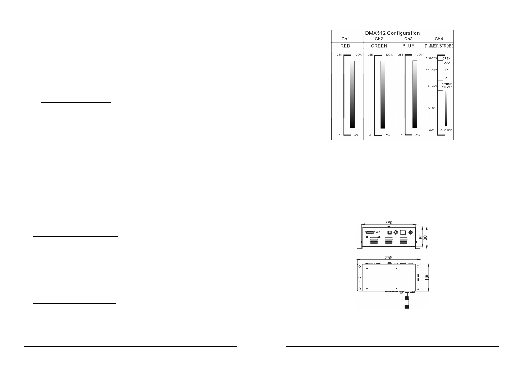
4 DMX channels needed:Ch1=red,Ch2=green, Ch3=Blue, Ch4=Dimmer/strobe.
Enclosure prepared for easy installing against the wall.
No fan cooling: completely silent!
BEFORE USE
Check the contents:
Check that the carton contains the following items:
Mini Led Manager
Mainscable
Output conversion cable
User manual
Some important instructions:
Beforeyou start using this unit, please check if there’s no transportation damage. Should there be any, do
not use the device and consult your dealerfirst.
Important:
for the user to strictly follow the safety instructions and warnings in this user manual. Any damage caused
bymishandling is not subject to warranty. The dealer will not accept responsibility for any resulting defects
orproblems caused bydisregarding this user manual.
Keep this booklet in a safe place for future consultation. If you sell the fixture, be sure to add this user
manual.
To protect the environment, please try to recycle the packing material as much as possible.
This device left our factory in perfect condition and well packaged. It is absolutely necessary
ENGLISH OPERATION MANUAL
SAFETY INSTRUCTIONS:
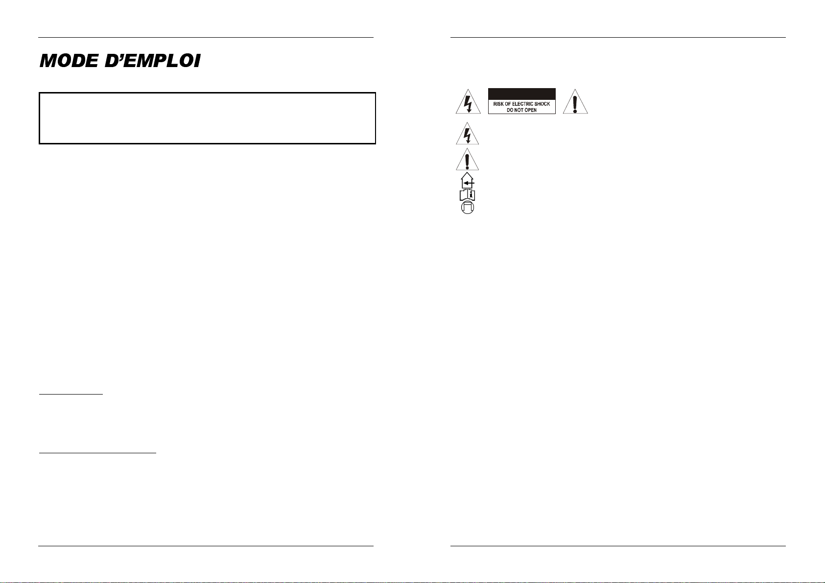
CAUTION
The lightning flash with arrowhead symbol within the equilateral triangle is intended to alert the
use or the presence of un-insulated “dangerous voltage”within the product’s enclosure that may
be of sufficient magnitude to constitute a risk of electric shock.
The exclamation point within the equilateral triangle is intended to alert the user to the presence
of important operation and maintenance (servicing) instructions in the literature accompanying
this appliance.
This symbol means:indoor use only
This symbol means:Readinstructions
This symbol means: Lamp ControlGear
To prevent fire or shock hazard, do not expose this appliance to rain ormoisture.
To avoid condensation to be formed inside, allow the unit to adapt to the surrounding temperatures when
bringing it into a warm room after transport. Condense sometimes prevents the unit from working at full
performance or may even cause damages.
This unit is forindoor use only.
Don’t placemetal objectsor spill liquid inside theunit. No objects filled with liquids, such as vases, shall be
placed on this appliance. Electric shock or malfunction may result. If a foreign object enters the unit,
immediately disconnect the mains power.
No naked flame sources, such as lighted candles, should be placed on the appliance.
Don’t cover any ventilation openings as this may result in overheating.
Preventuse in dusty environmentsand clean the unit regularly.
Keep the unit awayfrom children.
Inexperienced persons should not operatethis device.
Maximumsave ambienttemperature is 40°C. Don’t use this unit at higher ambient temperatures.
Alwaysunplug the unit when it is not used for a longer time or beforeyou start servicing.
The electrical installation should be carried out by qualified personal only, according to the regulations for
electricaland mechanical safety in your country.
Check that the available voltageis not higher than the one statedon the rear panel of the unit.
The socket inlet shall remain operable fordisconnection from the mains.
The powercord should alwaysbe in perfect condition: switch the unit immediately off when the power cord
is squashed or damaged. It must be replaced by the manufacturer, its service agent or similarly qualified
persons in order to avoid a hazard
Never let the power-cord come into contact with other cables!
This appliancemust be earthed to in order comply with safety regulations.
In order to prevent electric shock, do not open the cover. Apart from the mains fuse there are no user
serviceablepartsinside.
Never repair a fuse or bypass the fuse holder. Always replace a damaged fuse with a fuse of the same
type and electrical specifications!
In the event of serious operating problems, stop using the appliance and contactyour dealer immediately.
Pleaseuse the original packing when the device is to be transported.
Due to safety reasons it is prohibited to make unauthorized modifications to the unit.
CAUTION: To reduce the risk of electric shock, do not
remove the top cover. No user-serviceable parts inside.
Referservicing to qualifiedservice personnel only.
JB SYSTEMS® 1/51 MINI LED MANAGER
MAINTENANCE
Clean by wiping with a polished cloth slightly dipped with water. Avoid getting water inside the unit. Do not
use volatile liquids such as benzene or thinner which will damage the unit.
Since this unit uses a cooling fan, the interior of the device should be cleaned annually using a vacuum
cleaneror air-jet.
Attention: We strongly recommend internal cleaning to be carried out by qualified personnel!
JB SYSTEMS® 2/51 MINI LED MANAGER
Page 4
ENGLISH OPERATION MANUAL
ENGLISH OPERATION MANUAL
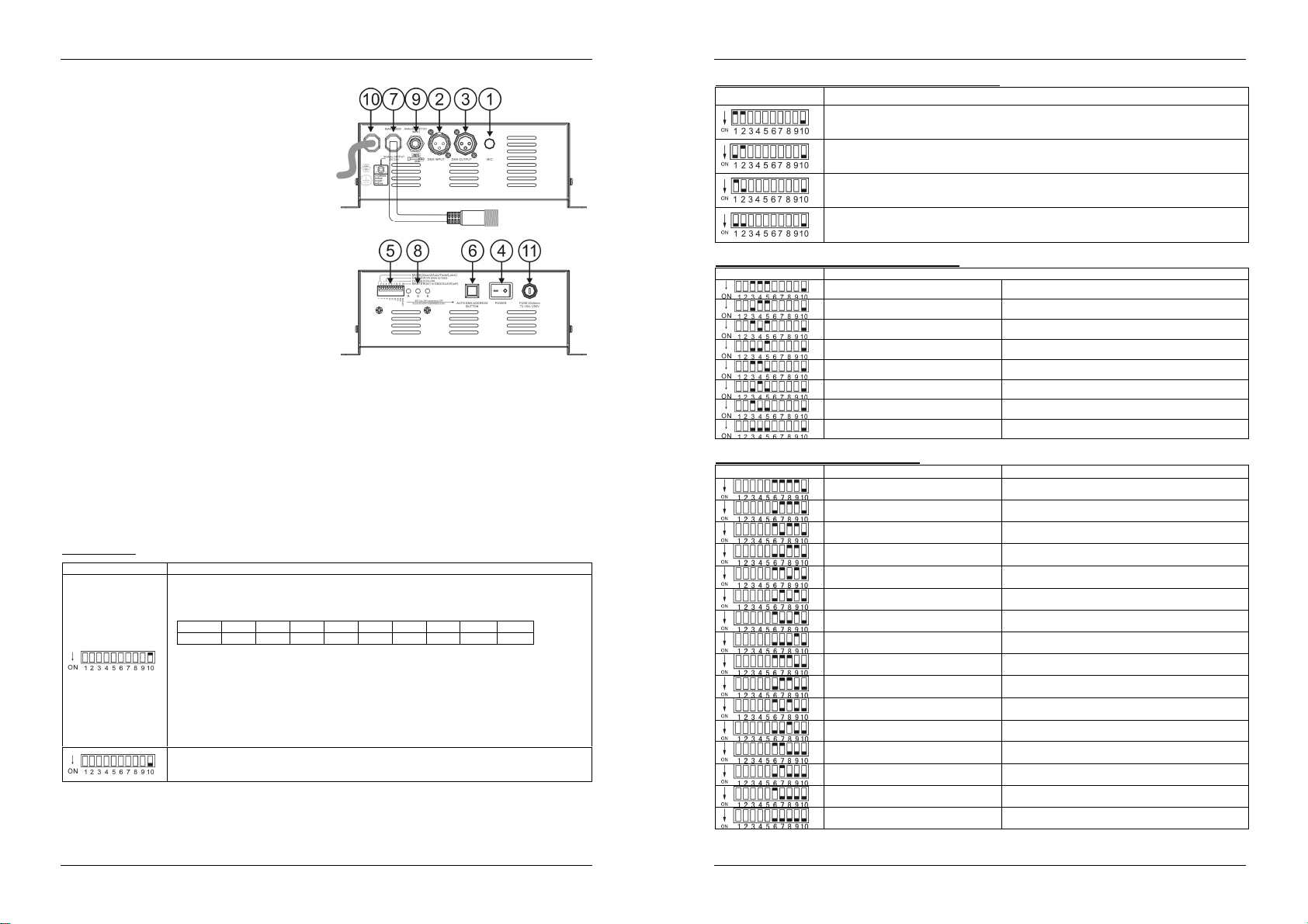
FUNCTIONS
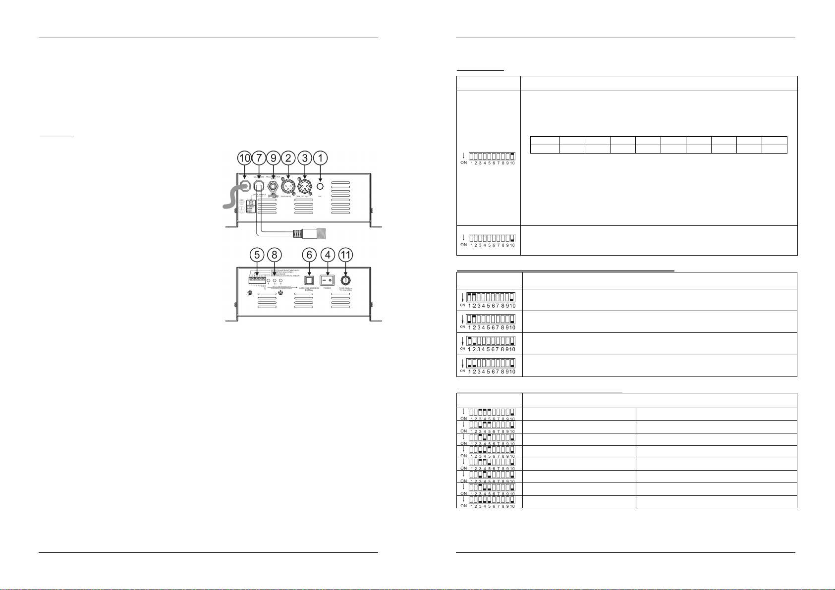
1. INTERNAL MICRO: used for sound activated
chases.
2. DMX INPUT: 3pin male XLR-connector used to
connect universal DMX-cables. This input
receives instructions from a DMX-controller or
from another Mini Led Manager when used in
master/slavemode.
3. DMX OUTPUT: 3pin female XLR-connector used
to connect the Mini Led Manager with the next
DMX appliance in the chain or with another Mini
Led Manager when used in master/slave mode.
The mini LED Manager can also be used as
controller for other LED projectors like for example
“LEDPAR56/64”
4. ON/OFFSWITCH: used to switch the unit on/off.
5. DIP SWITCHES: when used in DMX mode
(DIP10 = OFF) you can set the DMX-starting
address of the unit. When used in stand-alone
mode (master, DIP10 = ON), you can use the
DIP-switches to set different pre-programmed
options.
6. AUTO DMX ADDRESS BUTTON: see further to learn how toset the DMX address easily.
7. OUTPUT CABLE: used to connect different 24Vdc common anode LED projectors. (max. load: 100W)
The cable uses a special 4pin female connector. You can use the supplied conversion cable to easily
connect different projectors.
8. OUTPUT MONITOR: you can check theseparateoutput state of the 3 colors (red, green and blue)
9. ANALOG SWITCH INPUT: used to connect any external analog switch. This external switch can be
used to switch the general output of the Mini LED Manager on/off. (external blackout) See further for
more information on how to connect the analog switch.
10. MAINS INPUT: with IEC socket and integrated fuse holder, connectthe supplied mains cable here.
11. MAINS FUSE: Always replace this fuse with a fuse that has the same characteristics! (250V/3,15A)
DIP SWITCH SETTINGS
Dip switch10:
Dipswitch setting Function
DIP10 = OFF DMX / Slave operation
You can use the automatic DMX addressing feature (see further) or traditional DIP-switches.
Use the dipswitches 1~9to set the DMX address from 0 to 511.
The first 9 DIP-switches correspond to a certain DMX-value:
DIP #1 #2 #3 #4 #5 #6 #7 #8 #9
Value 1 2 4 8 16 32 64 128 256
You can combine the values of these switches to obtain any starting address between 1 and
512:
Begin address = 01 switch 1=ON values: 1
Begin address = 05 switch 1+3=ON values: 1+4 = 5
Begin address = 09 switch 1+4=ON values: 1+8 = 9
Begin address = 13 switch 1+3+4=ON values: 1+4+8 = 13
…
Begin address = 62 switch2+3+4+5+6=ON values: 2+4+8+16+32 = 62
DIP10 = ON Master operation(stand-alone)
Use the dipswitches 1~9tosetthemode, speed, patterns, fixed color color…etcfunctions.
Below each of these functions is explained in detail.
Dip switches1&2: Mode (Sound/auto/fade/fixedcolor):
Dipswitch setting MODE
SOUND:internalmicrophone triggersthe selected patterns.
AUTO:the selected pattern runs automatically atthe desired speed.
FADE: the colors of the selected pattern fade smoothlyat the desired speed.
FIXED COLOR: use DIP-switches 6, 7, 8 & 9 to select the desired colors.
Dip switches 3,4 & 5:Speed (from fast to slow):
Dipswitch setting Auto/FadeMode
Speed 1 Fast
Speed 2
Speed 3
Speed 4
Speed 5
Speed 6
Speed 7
Speed 8 Slow
DIP switches 6,7 ,8 & 9: Chase & Color:
Dipswitchsetting SOUND & AUTO MODE FIXED COLOR MODE
Standard chase White
Brightchase Red
Moodchase Orange
Spectrumrandom chase Amber
Spectrumsequencechase Yellow
Dynamicchase Light Yellow
Chase Red – Cyan AppleGreen
ChaseGreen – Purple LightGreen
ChaseBlue – Red Green
ChaseYellow – Blue Cyan
ChaseRed – Green Blue
ChaseYellow – Green Deep Blue
ChaseCyan – Orange Purple
ChaseGreen - Light purple Light Purple
ChaseRed – Yellow Magenta
Chase Gold Yellow - Blue Pink
JB SYSTEMS® 3/51 MINI LED MANAGER
JB SYSTEMS® 4/51 MINI LED MANAGER
Page 5
ENGLISH OPERATION MANUAL
ENGLISH OPERATION MANUAL
ELECTRICAL INSTALLATION
The electrical installation should be carried out by qualified personal only, according to the
regulationsfor electrical and mechanical safety in your country.
How to connect the LED-projectors to the output of the unit:
Important: Switch the Mini Led Manager OFF before you install the LED-projectors! The maximum
total load of the Mini Led Manager is 100W, spread over 3 colors: each of the 3 colors has a max.
load of 33W!Make sure not to overload the output cable!
The output cable (6) uses a special 4pin connector. Two different types of passive LED projectorscan be
connected:
A. LED Projectors with a special 4pin connector (ex. LED STRIP):
This is the easiest way to
make the connections. Fix
all projectors properly and
daisy chain their in/output
cables until you reach the
maximumallowed load. Make sure to fasten the plastic ring of the connector.
B. LED Projectors with open wires (ex. LED GROUND LIGHT):
Use the supplied conversion cable and connect the internal 4 wires to the corresponding 4 wires of
the LED projectors. (in most cases the colors of the wires match with the LED colors) Make sure not
to exceed the maximum allowed load:
Whitewire: This is the commonwire (anode)
Red wire: This the power for the red LEDs (max. 33W)
Greenwire: This the power for the greenLEDs (max.33W)
Bluewire: This the powerfor the blue LEDs (max. 33W)
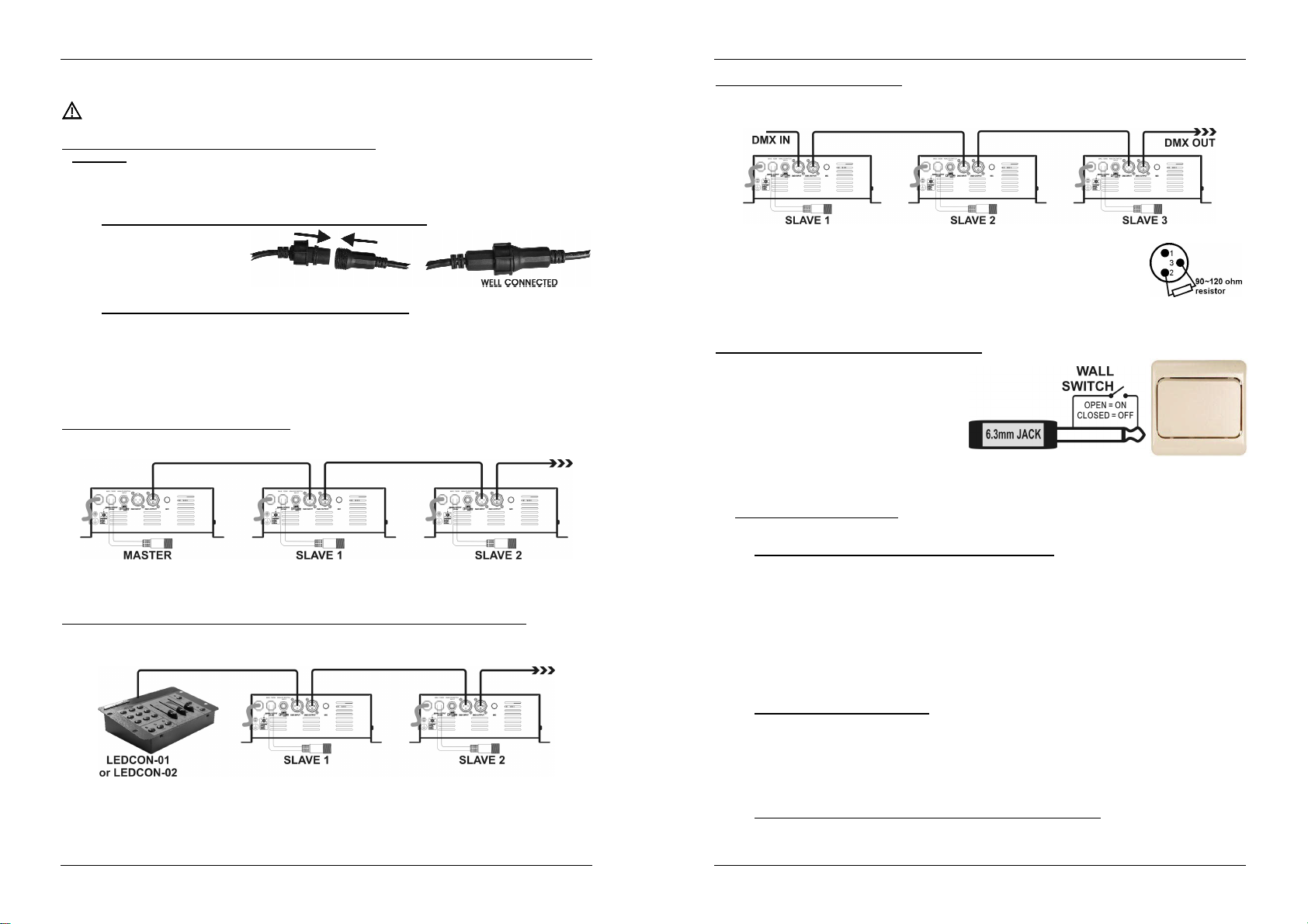
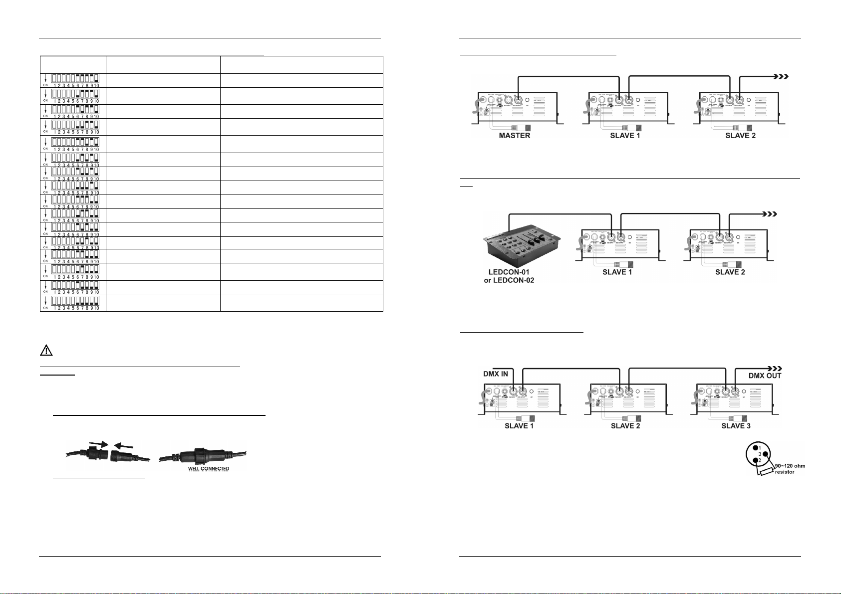
ElectricalinstallationinMaster/slave-mode:
You need to“daisy chain” theDMX in/outputs of 2 or more units with a good quality balanced cable
Switch the unit with the free DMX-input connector to master, the other units are automatically switched
as slaves.The DIP-switcheson the slave units are disabled.
ElectricalinstallationinMaster/slave-mode with the LEDCON-02 (or LEDCON-01)remote:
You need to “daisy chain” the DMX in/outputs of 1 or more units with the output of the LEDCON-02
remoteusing a good quality balanced cable
The LEDCON-02 remote will be used to control all connected slaves. The Mini Led Managers are
automatically switchedas slaves. The DIP-switches on the slaveunits are disabled.
Electrical installation in DMX-mode:
The DMX-protocol is a widely used high speed signal to control intelligent light equipment. You need to
“daisy chain” your DMX controller and all the connectedunits with a good qualitybalanced cable
To prevent strange behavior of the light effects, due to interferences,you must use
a 90Ω to 120Ω terminator at the end of the chain. Never use Y-splitter cables, this
simply won’t work!
DIP-switch 10 must be set to OFF on all units. Each unit in the chain needs its
properstart address so it knows which commands fromthe DMX-controller it hasto
decode.When you need a lot of power you can use several Mini Led Managers and give them the same
startaddress. See the previous chapter to learn how to set the DMXaddresses.
Connecting an external analogswitch for blackout:
Using any ordinary on/off switch, you can put the
output ofthe Mini LED Manager in blackout, even
if it’s controlled by DMX: for example you can use
a regular “wall switch” to turn the LED-light on/off
at any moment!
Connected wall switch in OFF position
(contactsopen):output = ON
Connected wall switch in ON position
(contactsclosed): output = OFF (blackout)
AUTOMATIC DMX ADDRESSING
How to set the DMXaddresses:
There are 3 ways to set the DMX-address of the units. If you use setting options A or B you MUST set
ALL DIP-switches to OFF position.
A. Setting individualDMX-addressesper miniLED Manager:
Makesure that ALL DIP-switches are set to OFF position!
Makesure the DMX cables of all units are connected.
Connect the first unit to a universal DMX controller.
Connect all units to the mains so they are switched on.
Set all DMX-channels on your DMX-controller to zero (value 000).
Set the DMX-channel, that you want to assign as DMX-start address on your mini LED Manager
tomaximum (value 255)
Press the “Auto DMX address” button (6) on the mini LED Manager shortly.
If you want to set another unit to the same DMX-start address, simply press it’s “Auto DMX
address” button (6) and it will receive the same address.
Done!
An example to make things clear:
We will set the DMX start address of a mini LEDManager to 106:
Connect the mini LED Manager to the DMX-controller as described above and make sure all is
switchedon.
Set all DMX-channels on the controller to zero (000)
Now setDMX-channel 106 to maximum (255)
Press the “AutoDMX address” button (6) on the mini LED Manager shortly.
Done! Your mini LED Manager now has DMX address 106!
B. Automatic DMX-addressing, starting from anygivenstart address:
To save a lot of time (imagine the time it takes to set the DIP switches of 16 units…) you can set the
DMX addresses of all units in the DMX-chain just by the push of a button. No need to calculate the
JB SYSTEMS® 5/51 MINI LED MANAGER
JB SYSTEMS® 6/51 MINI LED MANAGER
Page 6
ENGLISH OPERATION MANUAL
starting address of each individual unit,this will be done for you!
Makesure that ALL DIP-switches are set to OFF position!
Makesure the DMX cables of all units are connected.
Connect the first unit to a universal DMX controller.
Connect all units to the mains so they are switched on.
Set all DMX-channelson your DMX-controller to zero (value 000).
Set the DMX-channel, that you want to assign as DMX-start address on your mini LED Manager,
tomaximum (value 255)
Press the “Auto DMX address” button (6) on the first mini LED Manager in the chain for about
5seconds.
Done! The first mini LED Manager in the chain will receive the DMX-start address you chose
and it will automatically calculate and program the DMX addresses of all the other units in the
DMX-chain!
An example to make things clear:
We want to set the DMX-addresses of 16 units, the DMX start address of the first mini LED
Managermust be 202:
Connect all mini LED Manager to the DMX-controller as described above and make sure all are
switchedon.
Set all DMX-channels on the controllerto zero (000)
Now setDMX-channel 202 to maximum (255)
Press the “Auto DMX address” button (6) on the first mini LED Manager in the chain for about
5seconds.
Done! The first mini LED Manager in the chain willreceive DMX-startaddress 202 and it will
automatically calculate and program the DMX addresses of all the other units in the DMX-chain!
This means that the 2ndmini LED Manager automatically receives address 206, the 3rdhas
address210, …, until the 16thmini LED Manager who automatically receives start address 262.
Youjust programmed 16 mini LED Manager, this tookyou about 10seconds!!!
Remark: you can mix the units with other DMX-effects that don’t have the automatic DMXaddressing option. In that case you still have to set the DMX-addresses of these DMX-effects
manually! You can also mix the Mini LED Managers with other JB Systems LED products that have
the auto DMX-feature.They will also automaticallyreceive theirDMX-addresses.
OPERATING INSTRUCTIONS
A. Standalone 1unit:
Connect the LED projectors to the Mini Led Manager as indicatedin the previous chapters.
Switch the unit on and refer to the chapter “DIP SWITCH SETTINGS” to make yourself familiar with
thevariousfunctions of the fadersand buttons.
B. Two or more units in master/slave setup:
Connect the LED projectors to the Mini Led Managers as indicated in the previous chapters.
Connect the units with each other as explained in the chapterabout electrical installations.
Switch the Mini Led Managers on. You can only use the controls on the master unit, the controls on
the slaves are disabled. Refer to the chapter “DIP SWITCH SETTINGS” to make yourself familiar with
the various functions of the faders and buttons on the master unit.
C. Connect the optional LEDCON-02 (or LEDCON-01) for remote control:
In most cases the MINI LED MANAGER will be installed on a wall, close to the LED-projectors. If you
want to have easy access to its functions, you can connect the LEDCON-02 (or LEDCON-01) remote
controller to the (first) Mini Led Manager. The other connections are identical to those of the standalone
or master/slavesetups. Don’t forget to perform the automaticaddressing on the LEDCON-02!!!
D. Controlled by universal DMX-controller:
Connect the LED projectors to the Mini Led Manager(s) as indicatedin the previouschapters.
Connect the Mini Led Manager(s) with all other DMX-appliances in the DMX-chain.
Switch all units on and set the proper DMX-addresses. (don’t forget to set DIP-switch 10 to OFF)
Switch your universal DMX-controller on and refer to the DMX chart below to control the connected
Mini Led Managers:
ENGLISH OPERATION MANUAL
SPECIFICATIONS
Power Input: AC230V~ 50Hz
Fuse: 3,15A / 250V slowblow(20mm glass)
Outputvoltage to LEDs: DC24V common anode
Outputpower to LEDs: 1x 100W max
DMX connections: 3pinXLR (DMX-512standard)
DMX channels: 4 (CH1: red,CH2: green,CH3:blue, CH4:dimmer/strobe)
Audio input: None,internal microphone
Size: 255 ×110×88mm
Weight: 1,82kg
You can downloadthe latest version of thisuser manual on our website: www.beglec.com
Every informationis subject to change without prior notice
o Red: 33W max.
o Green: 33W max.
o Blue: 33W max.
JB SYSTEMS® 7/51 MINI LED MANAGER
JB SYSTEMS® 8/51 MINI LED MANAGER
Page 7
FRANCAIS MODE D’EMPLOI
ATTENTION
:
afin de réduire le risque d’électrocution,
FRANCAIS MODE D’EMPLOI
Afinde protéger l’environnement, merci de recyclerles emballages autant que possible.
Nous vous remercions d’avoir acheté ce produit JB Systems®. Veuillez lire ce mode d’emploi très
attentivement afin de pouvoir exploiter toutesles possibilités de cet appareil.
EN VOUS INSCRIVANT POUR LA LETTRE D’INFORMATION VOUS SEREZ TOUJOURS
TENU AU COURANT DES DERNIERES NOUVELLES CONCERNANT NOS PRODUITS:
NOUVEAUTES,ACTIONS SPECIALES,JOURNEES PORTES OUVERTES, ETC.
SURFEZ SUR: WWW.BEGLEC.COM ET INSCRIVEZ-VOUS
CARACTERISTIQUES
Cet appareil ne produit pas d’interférences radio. Il répond aux exigences nationales et européennes. La
conformité aété établie et les déclarations etdocumentscorrespondants ont été déposés par le fabricant.
Alimentation polyvalentepour toutessortes de projecteurs RVB LED passifs
Différentsmodes de fonctionnementsont possibles :
Fixedcolors mode: accès immédiataux 16 couleurs préprogrammées
Auto chase mode : 16 séquences de poursuite différentes, défilement des couleurs à 8 vitesses
différentes
Sound chase mode : 16 séquences de poursuite différentes, défilement des couleurs réagissant au
signalaudio
Fade chase mode: 16 séquences de poursuite différentes,défilementdes couleurs en fondu enchaîné,
à 8 vitessesdifférentes
N'importe quel interrupteur mural peut être utilisé pour éteindre/allumer les projecteurs connectés, même
quandl’appareil est utilisé en mode DMX.
Toutesles fonctions peuventêtre contrôlées de différentesmanières :
directementà partir du MINILED MANAGER
au moyen d'une commandeà distance, LEDCON-01 ouLEDCON-02
au moyen d'un LEDMANAGERde 300 watts
au moyen de n'importequel contrôleur DMX standard
Plusieurs MINI LED MANAGERs peuvent être utilisés ensemble en mode maître/esclave pour obtenir une
puissance élevée et un ensemble entièrement synchronisé
100 wattsde puissance avec une sortie en 24V CA (R+G+B)et avec coupe-circuits de protection
Utilisationde 4 canaux DMX : Ch1=rouge;Ch2=vert ;Ch3=bleu ; Ch4=Dimmer/stroboscope
Le boîtier est conçu pour permettreune installationfacilesur un mur
Pas de ventilation forcée par ventilateur,ce qui fait que l’appareil ne fait aucun bruit
AVANT L’UTILISATION
Vérifiez le contenu:
Vérifiezsi laboitecontient bien les articles suivants :
MINI LED MANAGER
Câbled’alimentation
Câble d'alimentation servant d'adaptateur
Moded’emploi
Quelquesinstructionsimportantes:
Avant d’utiliser cet appareil, assurez-vous de l’absence de dommage lié au transport. En cas
d’endommagement,n’utilisez pas l’appareil et contactez le vendeur.
Important:
l’utilisateur suive les instructions de sécurité et avertissements inclus dans ce manuel. La garantie ne
s’applique pas en cas de dommage lié à une utilisation incorrecte. Le vendeur ne prend pas la
responsabilité des défauts ou de tout problème résultant du fait de n’avoir pas tenu compte des mises en
garde de ce manuel.
Conservez ce manuel dans un endroit sûr pour toute consultation future. Si vous vendez l’appareil,
assurez-vous d’y joindre ce manuel également.
Cet appareil a quitté notre usine en parfaite condition et bien emballé. Il est primordial que
INSTRUCTIONS DE SECURITE:
CAUTION
La flèche dans un triangle met l'utilisateur en garde contre la présence de haute tension sans
isolationdans l'appareil,ce qui peut causer un risque d'électrocution.
Un point d'exclamation dans un triangle prévient de la présence d'instructions relatives au
fonctionnement et à la maintenancese trouvantdans le manuel fourni avec l'appareil.
Ce symbole signifie: uniquement pour usageà l'intérieur.
Ce symbole signifie : Lire le mode d’emploi.
Ce symbole signifie: Lamp Control Gear
Afin d’éviter tout risque d’incendie ou de décharge électrique, ne pas exposer cet appareil à la pluie ou
l’humidité.
Pour éviterla formation de condensation à l’intérieur de l’appareil, patientez quelques minutes pour laisser
l’appareil s’adapter à la température ambiante lorsqu’il arrive dans une pièce chauffée après le transport.
La condensation empêche l'appareil de fonctionner manière optimale, et elle peut même causer des
dommages.
Cetappareilest destiné à une utilisation à l’intérieur uniquement.
Ne pas insérer d’objet métallique ou renverser de liquide dans l’appareil. Aucun objet contenant un liquide,
tels que des vases, ne peut être placé sur cet appareil. Cela risquerait de provoquer une décharge
électrique ou un dysfonctionnement. Si un corps étranger est introduit dans l’appareil, déconnectez
immédiatement de la source d’alimentation.
Aucune source de flamme nue, telleque des bougies allumées, ne peut être placée sur l'appareil.
Ne pas couvrir lesorifices de ventilation,un risque de surchauffeen résulterait.
Ne pas utiliser l'appareil dans un environnement poussiéreux et le nettoyerrégulièrement.
Ne pas laisser l'appareil à portée des enfants.
Lespersonnes non expérimentées ne doivent pas utiliser cet appareil.
La température ambiantemaximale d’utilisation de l’appareil est de 45°C. Ne pas l’utiliser au-delà de cette
température.
Débranchez toujours l’appareil si vous ne l’utilisez pas de manière prolongée ou avant d’entreprendredes
réparations.
Les installations électriques ne peuvent être faites que par du personnel qualifié et conformément aux
règlements de sécurité électrique et mécanique en vigueurdans votre pays.
Assurez-vous que la tension d’alimentation de la source d’alimentation de la zone dans laquelle vous vous
trouvezne dépasse pas celle indiquée à l’arrière de l’appareil.
La prise seratoujours accessible pour que le cordon secteur puisse être enlevé à chaque moment.
Le cordon d’alimentationdoit toujours être en condition parfaite. Mettezimmédiatementl’unité hors tension
si le cordon est écrasé ou endommagé. Pour éviter tout risque de choc électrique, le cordon doit être
remplacé par le constructeur, son agent ou un technicien qualifié.
Ne laissez jamais le cordon d’alimentation entrer en contact avecd’autres câbles !
L’appareil doit être à la masse selon les règles de sécurité.
Utiliseztoujours des câbles appropriés et certifiés lorsque vous installez l'appareil.
Pour éviter toute décharge électrique, ne pas ouvrir l’appareil. En dehors des ampoules et du fusible
principal, il n’y a pas de pièces pouvant être changées par l’utilisateur à l’intérieur.
Nejamais
un fusible de même type et ayant lesmêmes spécificationsélectriques !
En cas de problèmes de fonctionnement sérieux, arrêtez toute utilisation de l’appareil et contactez votre
revendeurimmédiatement.
Utilisezl’emballaged’originesi l’appareil doit êtretransporté.
réparer ou court-circuiter un fusible. Remplacez
n’enlevez jamais le couvercle de l’appareil. Il n’y a aucune
pièce à l’intérieur de l’appareil que vous puissiez
remplacer vous-même. Confiez l’entretien uniquement à
des techniciens qualifiés.
systématiquement
un fusibleendommagé par
JB SYSTEMS
®
9/51 MINI LED MANAGER
JB SYSTEMS
®
10/51 MINI LED MANAGER
Page 8
FRANCAIS MODE D’EMPLOI
FRANCAIS MODE D’EMPLOI
Pour des raisons de sécurité, il est interdit d’apporter une quelconque modification à l’unité non
spécifiquement autoriséeparles parties responsables.
ENTRETIEN
Nettoyez l’appareil à l’aide d’un chiffon doux,légèrement humide. Evitez d’introduire de l’eau à l’intérieur
de l’appareil. N’utilisez pas de produits volatiles tels le benzène ou le thinner qui peuvent endommager
l’appareil.
Étant donné que cet appareil utilise un ventilateur, l’intérieur de l'appareil doit être nettoyé annuellementà
l'aide d'un aspirateurou d'air sous pression.
Attention: Nous conseillons que le nettoyageinterne se fasse par une personne qualifiée.
FONCTIONS
1) MICROPHONEINTERNE: microintégré.
2) ENTRÉE DMX: Connecteur XLR mâle à 3 broches
qui permet de connecter des câbles DMX. Cette
entrée reçoit des instructions provenant d’un
contrôleur DMX ou, en mode master/slave, d’un
autre MINILED MANAGER.
3) SORTIE DMX: Connecteur XLR femelleà 3 broches
qui permet de connecter le MINI LED MANAGER à
l’unité suivante de la chaîne DMX ou à un autre
MINI LED MANAGER en mode master/slave. Le
MINI LED MANAGER peut aussi être utilisé en tant
que contrôleur pour d'autres projecteurs à LED,
comme par exemple le modèle LED PAR 56/64.
4) INTERRUPTEUR ON/OFF: utilisé pour
allumer/éteindre l’appareil.
5) INTERRUPTEURS DIP : lorsque c'est le mode DMX
qui est utilisé (DIP 10 = OFF), vous pouvez régler
l'adresse DMX de départde l'appareil. Lorsque c'est
le mode stand alone qui est utilisé (DIP 10 = ON),
vous pouvezutiliser les interrupteursDIP afin de réglerles différentes options préprogrammées.
6) AUTO DMX ADDRESS: touche d’adressage DMX automatique. Voir plus loin pour plus d’informations
sur ce système qui facilite l’attribution des adressesDMX.
7) CABLE DE SORTIE : utilisé pour connecter les différents projecteurs à LED de 24V (CA, anode
commune, charge maximale : 100W). Ce câble est équipé d'un connecteur spécial femelleà 4 broches.
Vous pouvez utiliser le câble d'alimentation servant d'adaptateur (fourni) pour connecter aisément
plusieursprojecteurs.
8) SORTIE MONITOR : vous pouvez vérifier séparément le statut de sortie des 3 couleurs (rouge, vert et
bleu).
9) ENTREE POUR INTERRUPTEUR ANALOGIQUE : utilisé pour raccorder n'importe quel interrupteur
analogique externe. Cetinterrupteur externepeut être utilisé pour alimenter ou couper la sortie générale
du MINI LED MANAGER (black out externe Voir plus loin pour de plus amples informations
expliquantcomment connecter cet interrupteur analogique.
10)ALIMENTATION SECTEUR : munie d'une prise IEC avec fusible incorporé. Raccordez le câble
d’alimentation(fourni)à cette prise.
11)FUSIBLE : Peut uniquement êtreremplacépar un fusible aux caractéristiques identiques! (250V/3,15A)
REGLAGE DES INTERRUPTEURS DIP
Dip switch 10:
Réglage des interrupteursDIP
Interrupteurs DIP 1 & 2 : Mode (Sound/auto/fade/FIXED COLOR) :
Réglage des interrupteursDIP
Interrupteurs DIP 3, 4 & 5 (vitesse rapide à lente) :
Réglage des interrupteursDIP
Fonction
DIP10 = OFF Fonctionnementen modemaître/esclave
Vous pouvez utiliser le systèmed’adressage automatique(voirplus loin) ou les interrupteurs
DIPtraditionnels.
Use the dipswitches 1~9 to set the DMX address from0 to 511.
Les 9 premiersinterrupteurs DIP correspondent à une certaine valeur DMX.
DIP #1 #2 #3 #4 #5 #6 #7 #8 #9
Valeur 1 2 4 8 16 32 64 128 256
Combinez ces valeurs pour obtenir des adresses de démarrage comprises entre 1 et
512:
Adresse= 01 DIP 1=ON valeurs: 1
Adresse= 05 DIP 1+3=ON valeurs: 1+4 = 5
Adresse= 09 DIP 1+4=ON valeurs: 1+8 = 9
Adresse= 13 DIP1+3+4=ON valeurs: 1+4+8 =13
…
Adresse= 62 DIP2+3+4+5+6=ON valeurs: 2+4+8+16+32=62
DIP10 = ON Fonctionnementen mode autonome (stand alone)
Utilisez les 9 premiersinterrupteurs DIP pour réglerle mode de fonctionnement, la vitesse, les
motifs,les couleurs fixes, ... et les autres fonctions.
Chacune de ces fonctions est expliquée en détail ci-dessous.
MODE
SOUND: lemicro interne déclenche l'enchaînementdes motifs sélectionnés.
AUTO: le motifsélectionné évolue automatiquementà la vitesse désirée.
FADE: les couleursdu motifsélectionnéfaiblissent progressivement, àla vitesse désirée.
FIXED COLOR: utilisez les interrupteursDIP 6, 7, 8 & 9 poursélectionner les couleurs
désirées.
Mode Auto/Fade
Vitesse1 Rapide
Vitesse2
Vitesse3
Vitesse4
Vitesse5
Vitesse6
Vitesse7
Vitesse8 Lente
JB SYSTEMS
®
11/51 MINI LED MANAGER
JB SYSTEMS
®
12/51 MINI LED MANAGER
Page 9
FRANCAIS MODE D’EMPLOI
FRANCAIS MODE D’EMPLOI
interrupteurs DIP 6, 7, 8 & 9 :Séquencesde poursuite et couleurs :
Réglage des inter-
rupteursDIP
MODES SOUND & AUTO MODE COULEURSFIXES
Séquence de poursuite normale Blanc
Séquence de poursuitetrès
lumineuse
Séquencede poursuited'ambiance Orange
Séquence de poursuite àspectre
lumineuxaléatoire
Séquence de poursuite jouant sur le
spectrelumineux
Séquencede poursuitedynamique Jaune clair
Séquence de poursuite rouge - cyan Vert pomme
Séquence de poursuite vert - pourpre Vert clair
Séquence de poursuite bleu - rouge Vert
Séquence de poursuitejaune - bleu Cyan
Séquencede poursuite rouge - vert Bleu
Séquence de poursuitejaune - vert Bleu foncé
Séquencede poursuite cyan - orange Pourpre
Séquence de poursuite vert - pourpre
clair
Séquence de poursuite rouge - jaune Magenta
Séquencede poursuite jaune or -
bleu
Rouge
Ambre
Jaune
Pourpre clair
Rose
INSTALLATION ÉLECTRIQUE
L’installation électrique doit être faite uniquement par une personne qualifiée et selon les
règlements pour la sécurité électrique et mécanique dansvotre pays.
Commentrelier les projecteurs LED à la sortie de l'appareil:
Important: Coupez le MINI LED MANAGER avant d’installer les projecteurs LED! La charge maximale
du MINI LED MANAGER est 100W, répartie en 3 couleurs: chacune des 3 couleurs a une charge
maximale de 33W! Veuillezne pas surcharger le câble de sortie.
Le câble de sortie (6) utiliseun connecteur spécial 4pin. Deuxtypes de projecteurs passifs LED peuvent être
reliés:
A. Projecteurs LED avec connecteur spécial4pin(ex. LED STRIP):
C'est la manière la plus faciled'établir les connections. Fixez correctementtous les projecteurs en reliant
les câbles d'entrée et de sortie de chaque appareil jusqu'à ce que vous atteigniez la charge maximale
autorisée.Veillezà attacherl'anneau en plastique auxconnecteurs.
B. Projecteurs à filsdénudés:
Utilisez le câble d'alimentation servant d'adaptateur et connectez les 4 conducteurs aux 4 fils
correspondantsdes projecteursà LED. (dans la plupart des cas, les couleurs des fils correspondentaux
couleurs des LED). Assurez vous de ne pas dépasser la chargemaximale autorisée :
Fil blanc : commun (anode)
Fil rouge : conducteur de puissance pour les LED rouges (max. 33W)
Fil vert : conducteur de puissance pour les LED vertes (max. 33W)
Fil bleu : conducteurde puissance pour les LED bleues (max. 33W)
Installation électrique en mode maître/esclave:
Vous devez relier les entrées et les sorties DMX de 2 ou plusieurs appareils avec un câble symétrique
de bonne qualité
Réglez l'appareil dont le connecteur d'entrée DMX est libre en mode master, et les autres appareils
seront automatiquement mis en mode esclave. Les interrupteurs DIP des appareils esclaves seront mis
hors service.
Installation électrique en mode maître/esclave avec commande à distance LEDCON-02 (ou LEDCON-
01):
Vous devez relier les entrées/sorties DMX d’un ou plusieurs appareils avec la sortie du LEDCON-01
avec un bon câble symétrique
La commande à distance LEDCON-02 sera utilisée pour commander tous les esclaves de la chaîne
d'appareils. Les MINILED MANAGERsseront automatiquement mis en mode esclave. Les interrupteurs
DIPdes appareils esclaves seront mis hors service.
Installationélectrique en mode DMX:
Le protocole DMX est largement employé, c’est un signal à grande vitesse pour commander
l'équipement lumière. Vous devez relier votre contrôleur DMX et tous les appareils, avec un bon câble
symétrique.
Afin d’éviter que vos effets de lumière se comportent de manière étrange, à cause
d’interférences, utilisez des bouchons de 90Ω à 120Ω en fin de chaîne. N’utilisez
jamaisdes câbles de dérivation, ceci ne fonctionne pas!
L'interrupteur DIP 10 doitêtre réglé sur OFF sur tous les appareils. Chaque appareil
de la chaîne doit avoir sa propre adresse de démarrage afin de savoir quelles
commandes du contrôleur DMX il doit décoder. Si vous avez besoin de beaucoup de puissance, vous
pouvez employer plusieurs MINI LED MANAGERs et leur donner la même adresse de démarrage.
Reportez-vous au chapitre précédent pour savoir commentrégler les adresses DMX.
JB SYSTEMS
®
13/51 MINI LED MANAGER
JB SYSTEMS
®
14/51 MINI LED MANAGER
Page 10

FRANCAIS MODE D’EMPLOI
FRANCAIS MODE D’EMPLOI
Connexiond’un interrupteuranalogiqueexterne pour la fonction black-out:
Vous pouvezmettre les sorties du Mini LED
Manager en blackout à l’aide de n’importequel
interrupteur (on/off). Vous pouvezpar exemple
utiliserà tout moment un interrupteur mural pour
éteindre les effetsLED, même si l’appareil est
contrôlé par DMX:!
Interrupteur mural en position ETEINT
(contactsouverts):sortie = ALLUMÉ
Interrupteur mural en position ALLUMÉ (contacts fermés): sortie = ETEINT(blackout)
ADRESSAGE DMX AUTOMATIQUE
Commentrégler les adresses DMX:
Il existe trois façons de régler les adresses DMX des appareils. Si vous utilisez les possibilités A ou B,
vous DEVEZmettre tous les interrupteurs DIP en position OFF
A. Régler les adresses DMX par miniLED Manager:
Assurez-vous que TOUS les interrupteurs DIP sont en position OFF!
Assurez-vous que les câbles DMX de tousles appareils sont branchés.
Connectezle premier appareilsur le contrôleur DMX.
Brancheztous les appareilssur le secteur pour qu’ils soient tous allumés.
Metteztous les canaux DMXde votrecontrôleur DMX sur zéro. (valeur000).
Mettez le canal DMX, que vous voulez assigner comme adresse de départ sur le mini LED
Managersur maximum (valeur 255)
Poussezbrièvementle bouton “Adressage DMX auto”(6) du mini LED Manager.
Si vous voulez mettre un autre appareil sur la même adresse de départ, vous devez également
pousser le bouton “Adressage DMX auto” (6) de cet appareil.
Fini!
Un exemple pour rendre les choses claires:
Sivous souhaitez mettre l’adresse de départ d’un mini LED Managersur 106:
Connectez le mini LED Manager sur le contrôleur DMX comme décrit ci-dessus et allumez
l’ensemble.
Mettez tous les canaux DMX de votre contrôleur DMX sur zéro. (valeur 000).
Mettezle canal DMX 106 sur maximum (valeur255)
Poussez brièvement le bouton “Adressage DMX auto” (6) du mini LED Manager.
Fini! l’adresse de départ de votre mini LED Manager est 106!
B. Régler automatiquementlesadresses DMX:
Pour gagner du temps (imaginez le temps qu’il vous faudra pour régler les interrupteurs DIP de 16
appareils…) vous pouvez régler les adresses DMX de tous les appareils dans la chaîne DMX juste
en appuyant sur un bouton. Pas besoin de calculer l’adresse de départ de chaque appareil, cela
sera fait à votre place!
Assurez-vous que TOUS les interrupteurs DIP sont en position OFF!
Assurez-vous que les câbles DMX de tousles appareils sont branchés.
Connectezle premier appareilsur le contrôleur DMX.
Brancheztous les appareilssur le secteur pour qu’ils soient tous allumés.
Metteztous les canaux DMX de votre contrôleur DMX sur zéro. (valeur000).
Mettez le canal DMX, que vous voulez assigner comme adresse de départ sur le premier mini
LED Manager de la chaîne, sur maximum (valeur 255)
Poussez le bouton “AdressageDMX auto” (6) du premier mini LED Managerde la chaîne pendant
environ 5 secondes. (tous les projecteurs clignotes 1x)
Fini! Le premier mini LED Manager de la chaîne reçoit l’adresse de départ que vous avez
choisi. Les adresses de départ des autres projecteurs de la chaîne seront calculés et distribués
automatiquement !
Un exemple pour rendre les choses claires:
Imaginons que nous voulions donner des adresses DMX à 16 mini LED Manager. L’adresse de
départ du premier mini LED Manager de la chaîne est fixée sur 202.
Connectez les mini LED Manager sur le contrôleur DMX comme décrit ci-dessus et allumez
l’ensemble.
Mettez tous les canaux DMX de votre contrôleur DMX sur zéro. (valeur 000).
Mettezle canal DMX 202 sur maximum (valeur255)
Poussez le bouton “Adressage DMX auto” (6) du premier mini LED Manager pendant environ
5sec.
Fini! Le premier mini LED Manager de la chaîne reçoit l’adresse 202. Les adresses de départ
des autres mini LED Manager de la chaîne seront calculés et distribués automatiquement: le
deuxième mini LED Manager reçoit l’adresse 206, le troisième l’adresse 210, …, jusqu’au
seizièmemini LED Managerqui reçoit l’adresse 262.
Vousvenez de programmer 16projecteurs en 10 secondes !!!
Remarque: vous pouvez mélanger les appareils ensemble avec d’autres effets DMX qui ne
possèdent pas l’option adressage DMX automatique. Dans ce cas, il vous restera à régler les
adresses DMX de ces effets DMX manuellement! Vous pouvez également mélanger les mini Led
Manager avec d’autres produits LED de la marque JB Systems qui possèdent la fonction
d’adressage DMXautomatique. Ilsrecevrontégalement leuradresseDMXautomatiquement.
CONSIGNES D’UTILISATION
A. 1 appareil autonome:
Reliezles projecteurs LED aux MINILED MANAGERcommeindiqué dans les chapitres précédents.
Branchez l’appareil et consultez le chapitre ‘Réglages des interrupteurs DIP' pour vous familiariser
avecles diverses fonctionsdes curseurs et des touches.
Dans ce mode vous pouvez également régler l'horloge et employer les 3 minuteries ‘on/off’ comme
décrit dans le chapitreprécédent.
B. Installation de 2 ou plus d’appareils enmodemaître/esclave:
Reliezles projecteursLED aux MINILED MANAGERs comme indiqué dans les chapitres précédents.
Reliez les appareils les uns aux autres comme expliqué dans le chapitreinstallation électrique.
Branchez les MINI LED MANAGERs. Vous savez seulement employer les commandes de l’appareil
maître, les commandes sur les esclaves sont désactivées. Consultez le chapitre ‘Réglages des
interrupteurs DIP' pour vous familiariser avec les diverses fonctions des curseurs et des touches de
l’appareil maître.
C. Reliez le contrôleur avec la commande à distance LEDCON-02 (ou LEDCON)01):
Dans la plupart des cas, le MINILED MANAGER sera installé sur un mur, près des projecteurs LED. Si
vous voulez avoir un accès facile à ses fonctions, vous pouvez relier le contrôleur avec la commande à
distanceLEDCON-01 sur le premier MINI LED MANAGER. Les autres raccordements sont identiques à
l’installation autonome ou l’installation‘maître/esclave. N’oubliez pas d’exécuter l’adressage automatique
surle LEDCON-02!!!
D. Contrôlé par le contrôleur DMX universel:
Reliez les projecteurs LED aux MINI LED MANAGER(s) comme indiqué dans les chapitres
précédents.
Reliez les MINILED MANAGER(s) avec tous les autres appareils DMXdans la chaîne DMX.
Branchez tout les appareils et installez
l’adresse DMX correcte. (n'oubliez pas de
régler l'interrupteur DIP 10 sur OFF)
Branchez votre contrôleur DMX universel et
référez-vous au diagramme DMX ci-dessous
pour commander les MINI LED MANAGERs
de la chaîne :
JB SYSTEMS
®
15/51 MINI LED MANAGER
JB SYSTEMS
®
16/51 MINI LED MANAGER
Page 11

FRANCAIS MODE D’EMPLOI
SPÉCIFICATIONS
Alimentation: CA230V,50Hz
Fusibles: 3,15A /250V lent (20mm verre)
Tension des sorties LED : CC 24V,ANODE COMMUNE
Puissance des sorties LED : 1x 100W max. (Total = 300W max.)
o Rouge: 33W max.
o Vert: 33W max.
o Bleu: 33W max.
ConnexionDMX: priseXLR à 3 broches (standard DMX-512)
CanauxDMX: 4 (CH1: rouge, CH2:Vert;CH3: Bleu,CH4 : stroboscope/dimmer)
Entrée Audio: aucune, microinterne
Dimensions: 255 x 110 x 88 mm
Poids: 1,82 kg
Chacune de ces informationspeutêtre modifiée sans avertissementpréalable. Vous pouvez
télécharger la dernière version de ce mode d’emploide notre site Web: www.beglec.com
NEDERLANDS HANDLEIDING
Hartelijk dank voor de aankoop van dit JB Systems®product. Om ten volle te kunnen profiteren van alle
mogelijkheden en voor uw eigen veiligheid, gelieve de aanwijzingen zeer zorgvuldig te lezen voor U begint
het apparaat te gebruiken.
DOOR U OP ONZE MAILINGLIJST IN TE SCHRIJVEN ONTVANGT U STEEDS DE
LAATSTE INFORMATIE OVER ONZE PRODUCTEN: NIEUWIGHEDEN,SPECIALE
ACTIES, OPENDEURDAGEN, ENZ.
SURF NAAR: WWW.BEGLEC.COM
KARAKTERISTIEKEN
In dit apparaat is radio-interferentieonderdrukt. Dit product voldoet aan de gangbare Europese ennationale
voorschriften. Het is vastgesteld dat het apparaat er zich aan houdt en de desbetreffende verklaringen en
documenten zijn door de fabrikantafgegeven.
Het toestel is ontworpen om decoratieve lichteffecten te produceren en kan eventueel worden gebruikt in
lichtshows.
Erg veelzijdigevoeding voor allerlei passieveRGB LED-projectors.
Verschillendezelfstandige werkmodi:
Fixedcolor modus: Onmiddellijketoegang tot 16 voorgeprogrammeerde kleuren
Autochasemodus: 16 verschillende color chasesmet8 verschillende snelheden
Sound chase modus: 16 verschillendecolor chases met audio sturing
Fadechasemodus: 16 verschillende kleurchases die vloeiend faden op 8 verschillende snelheden.
Elkemuurschakelaar kan gebruikt worden om de aangeslotenLED-projecteren aan/uit te schakelen, zelfs
wanneeru werktin DMX-modus!
Allefunctieskunnen onmiddellijkgecontroleerdworden met:
De Mini LED manager
De optionele LEDCON-01 of LEDCON-02bediening
Een 300WattLED Manager
Elke standaard DMX-controller
Verscheidene Mini Led Managers kunnen samen gebruikt worden in Master/slave mode om hoge
vermogenste bekomen,vollediggesynchroniseerde setups.
100 Watt 24Vdcuitgang(R+G+B) met kortsluitbeveiliging
4DMXkanalen nodig: Ch1=rood,Ch2=groen,Ch3=blauw,Ch4=Dimmer/stroboscoop
Behuizing klaar voor gemakkelijkeinstallatietegen een muur
Lage ruis ventilatorkoeling voor extrabetrouwbaarheid
Geenventilatorkoeling:volledig geruisloos
JB SYSTEMS
EERSTE INGEBRUIKNAME
Controleer de inhoud:
Kijk na ofde verpakking volgende onderdelen bevat:
Mini Led Manager
Gebruiksaanwijzing
Uitgangomschakelingkabel
Netsnoer
Belangrijkeinstructies:
Controleervoor het eerstegebruik van het apparaat of het tijdens het transport beschadigd werd. Mocht er
schade zijn, gebruik het dan niet, maar raadpleeg eerst uw dealer.
Belangrijk:
de gebruiker de veiligheidsaanwijzingen en raadgevingen in deze gebruiksaanwijzing uiterst nauwkeurig
volgt. Elke schade veroorzaakt door verkeerd gebruik van het apparaat valt niet onder de garantie. De
dealer aanvaardt geen verantwoordelijkheid voor mankementen en problemen die komen door het
veronachtzamenvandezegebruiksaanwijzing.
®
17/51 MINI LED MANAGER
JB SYSTEMS
Dit apparaat verliet de fabriek in uitstekende staat en goed verpakt. Het is erg belangrijk dat
®
18/51 MINI LED MANAGER
Page 12

NEDERLANDS HANDLEIDING
WAARSCHUWING:
Om het risico op elektro
cutie zoveel
NEDERLANDS HANDLEIDING
Bewaar deze brochure op een veilige plaats om hem in de toekomst nogmaals te kunnen raadplegen.
Indien U het apparaat verkoopt, denkt Uer wel aan om de gebruiksaanwijzing bij tevoegen.
Om het milieu te beschermen, probeer zoveel mogelijk het verpakkingsmateriaal te recycleren.
VEILIGHEIDSVOORSCHRIFTEN:
CAUTION
De bliksempijl die zich in een gelijkbenige driehoek bevindt is bedoeld om u te wijzen op het
gebruik of de aanwezigheid van niet-geïsoleerdeonderdelen met een “gevaarlijke spanning” in
het toestel die voldoende kracht heeft om een risico van elektrocutiein te houden.
Het uitroepteken binnen de gelijkbenige driehoek is bedoeld om de gebruiker erop te wijzen dat
er in de meegeleverde literatuur belangrijke gebruik en onderhoudsinstructies vermeld staan
betreffendedit onderdeel.
Dit symbool betekent: het apparaat mag enkel binnenhuis wordengebruikt.
Dit symbool betekent: Lees de handleiding!
Dit symboolbetekent:Controletoestel voor lamp
Stel dit apparaat niet bloot aan regen of vocht, dit om het risico op brand en elektrische schokken te
voorkomen.
Om de vorming van condensatie binnenin te voorkomen,laat het apparaat aan de omgevingstemperatuur
wennen wanneer het, na het transport, naar een warm vertrek is overgebracht. Condensatie kan het
toestel soms verhinderen perfect te functioneren. Het kan soms zelfs schade aan het apparaat
toebrengen.
Gebruikditapparaat uitsluitend binnenshuis.
Plaats geen stukken metaal en mors geen vocht binnen in het toestel om elektrische schokken of storing
te vermijden. Objecten gevuld met water, zoals bvb. Vazen, mogen op dit apparaat worden geplaatst.
Indien er toch een vreemd voorwerp of water in het apparaat geraakt, moet U het direct van het lichtnet
afkoppelen.
Openvuur, zoals brandende kaarsen, mogen niet op het apparaatgeplaatst worden.
Bedekgeen enkele ventilatieopening omoververhitting te vermijden.
Zorg dat het toestelniet in een stoffige omgeving wordt gebruikt en maak het regelmatigschoon.
Houd het apparaatuit de buurt van kinderen.
Dit apparaat mag niet door onervarenpersonen bediend worden.
De maximum veilige omgevingstemperatuur is 40°C. Gebruik het apparaat dus niet bij hogere
temperaturen.
Trek altijd de stekker uit wanneer het apparaat gedurende langere tijd niet wordt gebruikt of alvorens met
deonderhoudsbeurt tebeginnen.
De elektrische installatie behoort uitsluitend uitgevoerd te worden door bevoegd personeel, volgens de in
uw land geldende regels betreffendeelektrische en mechanische veiligheid.
Controleer dat de beschikbare spanning niet hoger is dan die aangegeven op de achterzijde van het
toestel.
Het stopcontact zal steeds vrij toegankelijk blijven zodat de stroomkabel op elk moment kan worden
uitgetrokken.
De elektrische kabel behoort altijd in uitstekendestaat te zijn. Zet het apparaatonmiddellijk af als de
elektrischekabelgekneusd of beschadigd is. De kabel moet vervangen worden door de fabrikant zelf, zijn
dealer of vergelijkbare bekwamepersonenom een brand te voorkomen.
Laatde elektrische draad nooit in contact komen metandere draden.
Volgensde veiligheidsvoorschriftenmoet deze installatie geaardworden.
Om elektrische schokken te voorkomen, moet U de behuizing niet openen. Afgezien van de zekering
zittener geen onderdelen in die door de gebruiker moeten worden onderhouden.
Repareer nooit een zekering en overbrug de zekeringhouder nooit. Vervang een beschadigde zekering
steeds door een zekering van hetzelfdetype en met dezelfdeelektrischekenmerken.
mogelijk te vermijden mag u nooit de behuizing
verwijderen. Er bevinden zich geen onderdelen in het
toestel die u zelf kan herstellen. Laat de herstellingen
enkeluitvoerendoor een bevoegdetechnicus.
Ingevalvan ernstige problemen met het bedienen van het toestel, stopt U onmiddellijk het gebruik ervan.
Contacteeruw dealer voor een eventuele reparatie.
Gebruik best de originele verpakking als het toestelvervoerdmoet worden.
Om veiligheidsredenen is het verboden om ongeautoriseerde modificatiesaan het toestel aan te brengen.
ONDERHOUD
Reinig het toestel met een zacht, lichtjes bevochtigd doek. Vermijd water te morsen in het toestel.Gebruik
nooitvluchtige producten zoals benzeen ofthinner, dit kan het toestel beschadigen.
Aangezien dit apparaat een koelventilator gebruikt moet de binnenkant van het apparaat jaarlijks
schoongemaaktworden met behulp van een stofzuiger of perslucht.
Aandacht: Wij adviseren dat het interne schoonmaken door een gekwalificeerde persoon wordt
uitgevoerd.
FUNCTIES
1. INTERNE MICROFOON: gebruikt voor
geluidsgestuurdechases.
2. DMX INPUT: mannelijke 3 pinnen XLR-connector
die wordt gebruikt om universele DMX-kabels aan
te sluiten. Deze input ontvangt instructies van een
DMX-controller of van een andere Mini Led
Manager wanneer deze gebruikt worden in
master/slavemode.
3. DMX OUTPUT: vrouwelijke 3 pinnen XLRconnector die wordt gebruikt om de Mini Led
Manager met een anderDMX-toestel in de kring te
verbinden of met een andere Mini Led Manager
wanneer deze gebruikt wordt in master/slave
mode. De Mini LED Manager kan ook als
controller gebruikt worden voor andere LED
projectorenzoals bijvoorbeeld“LED PAR 56/64”
4. AAN/UIT SLEUTELSCHAKELAAR: gebruikt om
het toestel aan en uit te zetten.
5. DIP-SCHAKELAARS: Wanneer u het toestel
gebruikt in DMX modus (DIP 10 = OFF) kan u het DMX-startadres van het toestel instellen. Wanneer u
het toestel gebruikt in stand-alone modus (master, DIP10 = ON), kan u de DIP-schakelaars gebruiken
omverschillende voorafgeprogrammeerdeopties in te stellen.
6. AUTO DMX ADDRESS toets: zie verder in deze handleiding voor meer informatie over het gemakkelijk
instellenvan de DMX adressen.
7. UITGANGKABEL: gebruiktom verschillende 24Vdc LED projectors met gemeenschappelijke anode aan
te sluiten. (max. lading 100W) Elke kabel gebruikt een speciale vrouwelijke 4 pins connector. U kan de
meegeleverdeomschakelingkabel gebruiken om makkelijk verschillende projectorenaan te sluiten.
8. UITGANGMONITOR: U kan de aparteuitgangstatus van de 3 kleuren bekijken (rood, groenen blauw)
9. ANALOGE INGANGSSCHAKELAAR: Wordt gebruikt om elke externe analoge schakelaar aan te
sluiten. Deze externe schakelaar kan gebruikt worden om de hoofduitgang van de Mini LED Manager
AAN/UIT te schakelen (externe blackout) Kijk verder in deze handleiding voor meer informatie over
hetaansluiten van de analoge schakelaar.
10. NETAANSLUITING: IEC connector met geïntegreerde zekeringhouder, sluit de bijgeleverde netkabel
hier aan.
11. ZEKERING: vervang steeds deze zekering door een zekering met dezelfde karakteristieken!
(250V/3,15A)
JB SYSTEMS
®
19/51 MINI LED MANAGER
JB SYSTEMS
®
20/51 MINI LED MANAGER
Page 13

NEDERLANDS HANDLEIDING
NEDERLANDS HANDLEIDING
DIP SCHAKELAAR INSTELLINGEN
Dipschakelaar 10:
Dipswitch
instelling
Dip schakelaar 1&2: Modus (Sound/auto/fade/Fixedcolor):
Dipswitchinstelling MODUS
Dip schakelaars 3,4 & 5:Snelheid (snel traag):
Dipswitchsetting Auto/FadeMode
DIP schakelaars 6,7 ,8 & 9: Chase & Kleur:
Dipswitchsetting SOUND & AUTO MODUS FIXED COLOR MODUS
Functie
DIP10=OFF DMX / Slavebediening
U kunt de automatische DMX adressering gebruiken (zie verder) of de traditioneleDIPschakelaars.
gebruikt dipswitch 1~9 om het DMX adres in te stellen tussen 0 en 511
De eerste 9 Dip-schakelaarsreageren op een bepaalde DMX-waarde
Dip #1 #2 #3 #4 #5 #6 #7 #8 #9
Waarde 1 2 4 8 16 32 64 128 256
U kan deze waarden combineren om een startadres te bekomentussen 1 en 512:
Beginadres = 01 switch 1=ON waarden: 1
Beginadres = 05 switch 1+3=ON waarden: 1+4 = 5
Beginadres = 09 switch 1+4=ON waarden: 1+8 = 9
Beginadres = 13 switch 1+3+4=ON waarden: 1+4+8 = 13
…
Beginadres = 62 switch2+3+4+5+6=ON waarden:2+4+8+16+32=62
DIP10=ON Master bedizening(stand-alone)
gebruikt dipswitch 1~9 om de modus, snelheid, patronen, fixed colors,… in te stellen .
Hieronder wordtelk vandeze functiesverder uitgelegd
SOUND: de interne microfoonstuurtde geselecteerde patronen
AUTO: De geselecteerde patronenlopen automatischaf opde gewenste snelheid
FADE: De kleuren van het geselecteerde patrongaanvloeiend faden opde gewenste
snelheid
FIXED COLOR: Gebruik Dip- schakelaars 6, 7, 8 & 9 om de gewenste kleuren te selecteren.
Snelheid 1 Snel
Snelheid 2
Snelheid 3
Snelheid 4
Snelheid 5
Snelheid 6
Snelheid 7
Snelheid 8 Traag
Standaardchase Wit
Helderechase Rood
Zachtechase Oranje
Spectrumrandom chase Amber
Spectrumsequencechase geel
Dynamischechase Lichtgeel
Chase Rood – Cyaan Appelgroen
Chase Groen – Paars Lichtgroen
Chase Blauw – Rood Groen
ChaseGeel – Blauw Cyaan
ChaseRood – Groen Blauw
ChaseGeel – Groen Diepblauw
ChaseCyaan – Oranje Paars
Chase Groen - Lichtpaars Lichtpaars
ChaseRed – Geel Magenta
Chase Gold Geel - Blauw Roos
ELEKTRISCHE INSTALLATIE
De elektrische installatie mag alleen door een gekwalificeerdepersoon worden uitgevoerd,
die aan de normen voldoet in uw land voor de verordening vanelektrische en mechanische
veiligheid.
Hoe de LEDprojectors aan de uitgang van het toestel aansluiten:
Belangrijk:
Zet de Mini Led Manager AF alvorens u de LED projectors installeert! De max. totale belasting van de Mini
Led Manager is 100W, verdeeld over 3 kleuren: elk van de 3 kleuren heeft een max. belasting van 33W!
Zorg ervoor dat de outputkabelniet wordt overbelast.
De outputkabel (6) gebruiken een speciale 4 pins connector. Twee verschillende types passieve LED
projectorskunnen wordenaangesloten:
A. LED Projectors met een speciale 4 pins connector (Vb. LED STRIP):
Dit is de gemakkelijkste manier om de
verbindingen te maken. Bevestig
behoorlijk alle projectors en verbind
in/output van alle kabels tot u de
maximale toegestane belasting bereikt.
Zorg ervoor dat u de plastieken ring van de schakelaarvast maakt.
B. LED Projectors met open draad (Vb. LED GROUND LIGHT):
Gebruik de meegeleverde omschakelingskabel en sluit de 4 interne draden aan op de 4
corresponderendedraden van de LED projector.(in de meeste gevallen zullen de kleuren van de draden
overeenkomen met de LED kleuren). Verzeker u ervan dat u de totale toegestane belasting niet
overschrijdt.
Witte draad: Dit is degemeenschappelijke draad (anode)
Rodedraad: Dit het vermogen voor rode LEDs (max. 33W)
Groenedraad: Dit is het vermogen voor de groene LEDs (max. 33W)
Blauwedraad: Dit is het vermogenvoor de blauweLEDs (max. 33W)
JB SYSTEMS
®
21/51 MINI LED MANAGER
JB SYSTEMS
®
22/51 MINI LED MANAGER
Page 14

NEDERLANDS HANDLEIDING
NEDERLANDS HANDLEIDING
ElektrischeinstallatieinMaster/slave-mode:
U moet de DMX in/outputs van 2 of meer eenheden met een goede symmetrische kwaliteitskabel
doorlinken
Schakel het toestel met de vrije DMX-ingang om tot master, de andere toestellen zullen automatisch als
slave omgeschakeld worden. De DIP-schakelaarsop de slavetoestellenworden dan geblokkeerd.
Elektrischeinstallatie inMaster/slave-mode metde LEDCON-02 (of LEDCON-01) remote:
U moet de DMX in/outputs van 1 of meer eenheden met de output van de LEDCON-01 doorlinkenmet
een goede symmetrische kwaliteitskabel.
DeLEDCON-02 wordtgebruikt om alle verbonden slaves te controleren. De Mini Led Managers worden
automatischgeschakeld als slaves. De DIP-schakelaars op de slave eenheid zijn buiten gebruik.
Elektrische installatie in DMX-mode:
Het DMX-protocol is een veel gebruikt hogesnelheidssignaal om intelligent licht te controleren. U moet
uw DMX controller en alle aangesloten eenheden doorlinken met een goede symmetrische
kwaliteitskabel.
Om vreemd gedrag van de lichteffecten door storingen te verhinderen, moet u een 90Ω tot 120Ω
weerstand aan het eind van de kabel gebruiken. Gebruik nooit Y-splitser kabels, dit zal niet werken!
DIP-schakelaar 10 moet uitgeschakeld worden op alle toestellen. Elke eenheid in de kring heeft zijn
eigen beginadres zodat het weet welke bevelen het van de DMX-controller moet decoderen. Wanneer U
heel wat vermogen nodig heeft kan U verscheidene Mini Led Managers gebruiken en hen hetzelfde
beginadres geven. Bekijk hetvorige hoofdstuk om te leren hoe U DMX adressen moet programmeren.
Aansluiten van een gewone analoge schakelaar voor de black-out functie:
Gebruik een gewone aan/uit schakelaar.U kunt dan met deze schakelaar deuitgang van de Mini LED
Manager in black-outzetten,zelfswanneer de Mini Led Manager via DMX
aangestuurdwordt.Gebruik bijvoorbeeld een
gewone“muurschakelaar”om het LED licht op om
het even welk moment uit te schakelen.!
De verbonden schakelaar staat in de UIT
positie (contacten open): uitgang = AAN
De verbonden schakelaar staat in de AAN
positie (contacten open): uitgang = UIT (black-out)
Hoe het DMX adres in te stellen:
Er zijn drie manieren om de DMX adressen van de units in te stellen. Wanneer u the instellingsopties A,
B gebruiktdan MOET u ALLE DIP-switchesin UIT positie zetten
A. Het DMX-adres individueel per mini LED Manager instellen:
Wees er zeker van dat alle DIP-schakelaars in UIT positiestaan!
Wees er zekervan dat de DMX kabelsvan alletoestellen met elkaar verbonden zijn.
Sluit het eerste toestel aan op een universele DMX controller
Sluit alle toestellen aan op het net zodat ze allen aanslaan
Stelal uw DMX kanalen van uw DMX controllerin op zero ( waarde 000 )
Stel het DMX kanaal, dat u als DMX startadres wilt toewijzen aan uw mini LED Manager in op
het maximum ( waarde 255 )
Druk de “AutoDMXaddress” toets ( 6 ) op uw mini LEDManager kort in.
Wanneer u ook een ander toestel op het zelfde DMX startadres wil instellen, dient u simpelweg
zijn “Auto DMX address” toets (6) in te drukken en dan zal deze hetzelfde adres verkrijgen.
Klaar !
Een voorbeeld om de zaken te verduidelijken:
We zullen het DMX startadres van een mini LEDManager instellenop 106:
Sluit de mini LED Manager aan op de DMX controller zoals hierboven beschreven en wees er
zekervan dat alles aangeschakeld is.
Stelalle DMX kanalen van de controllerin op zero (000)
Stelnu het DMX kanaal106 in op het maximum (255)
Druk de “Auto DMX address” toets(6) van uw mini LED Manager kort in
Klaar uw mini LED Manager heeft nu als DMX startadres106 !
B. Automatische DMX adressering,startendvanaf een willekeurigingegeven startadres:
Om een hele hoop tijd te besparen ( beeldt uzelf in hoeveel tijd het instellenvan de Dip switches van
16 toestelleninneemt…) kan u de DMX adressen van alle toestellenin de DMX ketting duwen en dit
enkel door één toets in te drukken. U hoeft het startadres van elk individueel toestel niet te
berekenen,dit wordt voor u gedaan !
Wees er zeker van dat alle DIP-schakelaars in UIT positiestaan!
Wees er zekervan dat de DMX kabels van alletoestellen met elkaar verbonden zijn.
Sluit het eerste toestel aan op een universele DMX controller
Sluit alle toestellen aan op het net zodat ze allen aanslaan
Stelal uw DMX kanalen van uw DMX controllerin op zero ( waarde 000 )
Stel het DMX kanaal, dat u als DMX startadres wilt toewijzen aan uw mini LED Manager, in op
het maximum ( waarde 255 )
Druk de “Auto DMX address” toets ( 6 ) in op uw eerste mini LED Manager in de ketting
gedurende ongeveer5 seconden
Klaar ! De eerste mini LED Manager in de ketting zal het DMX startadres ontvangen dat u
gekozen heeft en de DMX adressen van alle andere toestellen in de DMX ketting worden
automatischberekend en geprogrammeerd!
Een voorbeeld om de zaken te verduidelijken:
We willen de DMX adressen van 16 toestellen instellen, het DMX startadres van de eerste mini LED
Managermoet 202 zijn
Sluit alle mini LED Managers aan op de DMX controller zoals hierboven beschreven en wees er
zekervan dat alles aangeschakeld is.
Stelalle DMX kanalen van de controller in op zero (000)
Stelnu het DMX kanaal 202 in op het maximum(255)
Druk de “Auto DMX address” toets (6) van de eerste mini LED Manager in de ketting in
gedurende ongeveer5 seconden.
Klaar ! De eerste mini LED Manager in de ketting zal het DMX startadres 202 ontvangen en
de DMX adressen van alle andere toestellen in de DMX ketting worden automatisch berekend
en geprogrammeerd! Dit betekent dat de 2demini LED Manager automatisch het adres 206 zal
ontvangen, de 3deheeft het adres 210,…, tot en met de 16demini LED Manager die automatisch
het startadres 262 zal ontvangen.
U heeft net 16 mini LED Managers geprogrammeerd en dit heeft slecht ongeveer 10 seconden
geduurd !!!
JB SYSTEMS
®
23/51 MINI LED MANAGER
JB SYSTEMS
®
24/51 MINI LED MANAGER
Page 15

NEDERLANDS HANDLEIDING
NEDERLANDS HANDLEIDING
Opmerking: U kunt de toestellen mixen met andere DMX effecten die de automatische DMX
adressering optie niet hebben. In dat geval dient u de DMX adressen van deze DMX effecten nog
steeds manueel in te stellen. U kunt de mini LED Managers mengen met andereLED producten van
JB Systems die wel over de automatische DMX adresseringsfunctie beschikken. Zo zullen ook
automatischhun DMX adres toegewezenkrijgen
BEDIENINGSVOORSCHRIFTEN
A. Zelfstandigeeenheid:
Sluit de LED projectors aan de Mini Led Manager aan zoals in de vorige hoofdstukken wordt vermeld.
Zet het toestel aan en neem een kijkje in het hoofdstuk “DIP SCHAKELAAR INSTELLINGEN” om met
de diverse functies van de faders en knoppen vertrouwdte geraken.
B. Twee of meer eenhedenin master/slave opstelling:
Sluit de LED projectors aan de Mini Led Manager aan zoals in de vorige hoofdstukken wordt vermeld.
Verbind de apparaten aan elkaar aan zoalsvermeld in het hoofdstuk elektrische installaties.
Zet de Mini Led Managers aan. U kan enkel de master controleren, de bedieningen op de slaves zijn
buiten gebruik. Neem een kijkje in het hoofdstuk “DIP SCHAKELAAR INSTELLINGEN” om met de
diversefuncties van de faders enknoppen vertrouwd te geraken.
C. Sluit de facultatieve LEDCON-02 (ofLEDCON-01) controlleraan alsafstandsbediening:
In de meeste gevallen zal de MINI LED MANAGER op een muur geïnstalleerd worden, dicht bij de LED
projectors. Als u gemakkelijke toegang tot zijn functies wilt hebben, kan u de LEDCON-01 controller op
de (eerste) Mini Led Manager aansluiten. De andere verbindingen zijn identiek als die van de
zelfstandige of master/slave instellingen. Vergeet niet de automatische adressering uit te voeren op de
LEDCON-02!!!
D. Gecontroleerd door de universele DMX-controller:
Sluit de LED projectors aan de Mini Led Manager aan zoals in de vorige hoofdstukken wordt vermeld.
Verbind de Mini Led Manager(s) met alle andereDMX apparaten in de DMX kring.
Zet alle eenheden aan en geef het juiste DMX adres in. (vergeet niet op DIP-schakelaar 10 uit te
schakelen)
Zet uw universele DMX-controller aan en neem een kijkje op de DMX-grafiek hieronder om de
verbonden Mini Led Managers te controleren:
TECHNISCHE KENMERKEN:
Netvoeding: wisselstroom230V,50Hz
Zekering: 3,15A/250Vtragezekering(20mm glas)
Outputvoltage voor de LEDs: DC 24V gemeenschappelijke anode
Ouputkracht voor de LEDs: 1x 100W max.
DMXconnecties: 3 pinnenXLR (DMX-512standaard)
DMX kanalen: 4 (kanaal1: rood, kanaal2: groen, kanaal3:blauw,
Audio ingang: geen, interne microfoon
Afmetingen: 255 x 110 x 88mm (zie tekeninghieronder)
Gewicht: 1,82kg
o Rood:33W max.
o Groen: 33W max.
o Blauw:33W max.
kanaal4:dimmer/stroboscoop)
JB SYSTEMS
U kan de recentste versie van deze handleidingop onzewebsite downloaden: www.beglec.com
®
25/51 MINI LED MANAGER
JB SYSTEMS
Elkeinlichting kanveranderen zonder waarschuwing vooraf
®
26/51 MINI LED MANAGER
Page 16

DEUTSCH BEDIENUNGSANLEITUNG
ACHTUNG:
Um sich nicht der Gefahr eines elektrischen
DEUTSCH BEDIENUNGSANLEITUNG
SICHERHEITSHINWEISE
Vielen Dank, dass Sie sich für den Erwerb dieses JBSystems®-Produkt entschieden haben. Bitte lesen sie
diese Bedienungsanleitung sorgfältig vor der Inbetriebnahme durch, zur vollen Ausschöpfung der
Möglichkeiten,die dieses Gerät bietetsowie,zu Ihrer eigenen Sicherheit.
EIGENSCHAFTEN
Das Gerät ist funkentstört und erfüllt die Anforderungen der europäischen und nationalen Bestimmungen.
EntsprechendeDokumentationliegt beim Herstellervor.
Äußerst universell einsetzbare Stromversorgung für alle Arten passiverRGB LED-Scheinwerfer.
Verschiedeneunabhängige Arbeitsmodi:
FixedColor Modus: Sofortiger Zugriff auf 16 vorprogrammierteFarben
AutoChaseModus: 16 unterschiedliche Farbchasermit 8 verschiedenen Geschwindigkeiten.
SoundChase Modus: 16 unterschiedlicheFarbchasermitMusiksteuerung
Fade Chase Modus: 16 verschiedene in 8 verschiedenen Geschwindigkeiten sanft übergehende
Farbchaser.
Gleich welcher Wandschalterkann benutzt werden, um die Leistungsabgabe ein/auszuschalten, sogar bei
der Verwendung im DMX-Modus!
AlleFunktionen können gesteuertwerden:
Direkt am MiniLed Manager
Mit einerwahlweisenLEDCON-01 oder LEDCON-02Fernsteuerung
Mit einer 300 WattLED-Manager
Mitjeder gängigenDMX-Steuerung
MehrereMini Led Manager können im Master/Slavemodus eingesetzt werden, um vollständige synchrone
Konfigurationenmiteiner höheren Leistung zu erhalten.
100WattLeistung24Vdc Ausgangsspannung. (R+G+B)mit Kurzschlussschutz
4 DMX Kanäle werden benötigt:Ch1=rot, Ch2=grün, Ch3=Blau, Ch4=Dimmer/Strobe.
Das Gehäuse ist für die einfache Wandmontage vorbereitet.
GeräuscharmeLüfterkühlung für größere Zuverlässigkeit.
Keine Lüfterkühlung: komplett lautlos!
VOR DER ERSTBENUTZUNG
Überprüfen Sie denInhalt:
FolgendeTeilemüssensich in der Geräteverpackung befinden:
Mini Led Manager
Netzkabel
Ausgang-Wandlerkabel
Bedienungsanleitung
WichtigeHinweise:
Vor der Erstbenutzung bitte das Gerät zuerst auf Transportschäden überprüfen. Sollte das Gerät einen
Schaden aufweisen, Gerät bitte nicht benutzen, sondern unverzüglich mit ihrem Händler in Verbindung
setzen.
Wichtiger Hinweis:
dass der Benutzer sich streng an die Sicherheitshinweise und Warnungen in der Bedienungsanleitung
hält. Schäden durch unsachgemäße Handhabung sind von der Garantie ausgeschlossen. Der Händler
übernimmt keine Verantwortung für Schäden, die durch Nichtbeachtung der Bedienungsanleitung
hervorgerufen wurden.
Die Bedienungsanleitung, für zukünftiges Nachschlagen, bitte aufbewahren. Bei Verkauf oder sonstiger
Weitergabedes Gerätes,bitte Bedienungsanleitung beifügen.
AusUmweltschutzgründen, Verpackung bitte wiederverwenden, oder richtig trennen.
Das Gerät hat das Werk unbeschädigt und gut verpackt verlassen. Es ist wichtig,
CAUTION
Das Blitzsymbol im Dreieck weist den Benutzer darauf hin, dass eine Berührungsgefahr mit
nicht isolierten Teilen im Geräteinneren, die eine gefährliche Spannung führen, besteht. Die
Spannung ist so hoch, das hier die Gefahr eines elektrischen Schlages besteht.
Das Ausrufezeichen im Dreieck weist den Benutzer auf wichtige Bedienungs- und
Wartungshinweise in den Dokumenten hin, diedem Gerät beiliegen.
DiesesSymbol bedeutet:Nurinnerhalb von Räumen verwenden.
Dieses Symbol bedeutet: Achtung! Bedienungsanleitung lesen!
DiesesSymbol bedeutet:Lampenvors chaltgerät
Zur Vermeidung von Stromschlag oder Feuer,Gerät bittenicht Regen oder Feuchtigkeit aussetzen.
Zur Vermeidung von Kondensation, lassen sie bitte nach Transport in eine warme Umgebung das Gerät
einige Zeit zum Temperaturausgleich stehen. Kondensation kann zu Leistungsverlust des Gerätes oder
garBeschädigungführen.
Gerätnicht im Freien und in feuchten Räumen und Umgebungen verwenden.
KeineMetallgegenständeoder Flüssigkeiten ins Innere des Geräts gelangen lassen. Keine mit Flüssigkeit
gefüllten Gegenstände z.B. Vasen, auf das Gerät stellen. Kurzschluss oder Fehlfunktion können die Folge
sein. Falls es doch einmal vorkommen sollte, bitte sofort Netzstecker ziehen und vom Stromkreis trennen.
OffeneBrandquellen, wie z.B.brennende Kerzen, sollten nicht auf das Gerät gestelltwerden.
Ventilationsöffnungen nicht abdecken, da Überhitzungsgefahr!
Nicht in staubiger Umgebung verwendenund regelmäßig reinigen.
Für Kinder unerreichbar aufbewahren.
UnerfahrenePersonen sollen das Gerät nicht bedienen.
Umgebungstemperaturdarf 40ºC nichtüberschreiten.
Stets Netzstecker ziehen, wenn Gerät für längeren Zeitraum nicht genutzt,oder es gewartet wird.
ElektrischeAnschlüssenur durch qualifiziertesFachpersonalüberprüfen lassen.
Sicherstellen,dass Netzspannung mit Geräteaufkleberübereinstimmt.
Die Netzsteckdose sollte immer gut erreichbar sein umdas Gerät vomNetz zu trennen.
Gerät nicht mit beschädigtem Netzkabel betreiben. Ist die Zugangsleitung beschädigt, muss diese durch
den Hersteller, seinen Vertrieboder durch eine Qualifizierte Person ersetzt werden.
Netzkabel nicht mit anderen Kabeln in Berührung kommen lassen!
AusschließlichvorschriftsmäßigeKabel zur Installationverwenden.
Gerät nicht öffnen. Abgesehen vom Tausch der Sicherung sind keine zu wartenden Bauteile im Gerät
enthalten.
Sicherung
Bei FehlfunktionGerätnicht benutzen und mit Händler in Verbindung setzen.
Bei Transport bitte Originalverpackungverwenden,um Schäden am Gerät zu vermeiden.
AusSicherheitsgründen dürfen andem Gerät keine unbefugten Veränderungen vorgenommenwerden.
niemals
reparieren oder überbrücken,sondern
Schlags auszusetzen, entfernen Sie keines der
Gehäuseteile. Im Geräteinneren befinden sich keine vom
Benutzer reparierbaren Teile. Überlassen Sie
Reparaturendemqualifizierten Kundendienst.
immer
mit gleichartiger Sicherung ersetzen!
WARTUNG
Die Reinigung des Gerätes erfolgt mit einem leicht mit Wasser angefeuchteten Tuch. Vermeiden Sie, dass
Wasser in das Gerätinnere gelangt. Verwenden Sie keine brennbaren Flüssigkeiten wie Benzin oder
Verdünner,welchedas Gerätbeschädigen würden.
Da dieses Gerät einen Kühlventilator verwendet, sollte das Innere des Geräts jährlich mit einem
StaubsaugerodereinemLuftstrahlgesäubert werden.
Achtung: Wir raten dringend, die Reinigung des Gehäuseinneren von qualifizierten Personen
durchführen zu lassen!
JB SYSTEMS
®
27/51 MINI LED MANAGER
JB SYSTEMS
®
28/51 MINI LED MANAGER
Page 17

DEUTSCH BEDIENUNGSANLEITUNG
DEUTSCH BEDIENUNGSANLEITUNG
FUNKTIONEN
1. INTERNESMIKRO: Für musikaktivierteChasern.
2. DMX-EINGGANG: Männlicher 3-poliger XLR-Stecker zum
Anschluss eines universellen DMX-Kabels. Dieser
Eingang empfängt Steuersignale von einem DMXController oder einem anderen Mini Led Manager, im
Master/Slavemodus.
3. DMX-AUSGANG: Weiblicher 3-poliger XLR-Stecker zum
Anschließen des Mini Led Manager an das nächste DMX
Gerät in der Kette oder an einen anderen Mini Led
Manager, im Master/Slavemodus. Der Mini LED Manager
kann auch als Steuerung für andere LED-Scheinwerferwie
zum Beispiel “LEDPAR56/64” verwendetwerden
4. EIN/AUSSCHALTER: EIN/AUS Schalten des Geräts.
5. DIP-SCHALTER: bei Verwendung im DMX-Modus (DIP10
= OFF) können Sie die DMX-Startadresse der Einheit
einstellen. Bei Verwendung im Standalone-Modus
(Master, DIP10 = ON) können Sie die DIP-Schalter zum
EinstellenverschiedenervoreingestellterOptionen benutzen.
6. AUTO DMX ADDRESS TASTE: Sehen sie weiter, wie sie einfach die DMX Adresse einstellen.
7. AUSGANG-KABEL: Anschluss der unterschiedlicher 24V DC LED-Scheinwerfer mit gemeinsamer
Anode. (max. Last: 100 W). Jedes Kabel verwendet eine spezielle 4-polige Buchse. Mit dem
mitgelieferten Wandlerkabel können sie leichtverschiedeneScheinwerfer anschließen.
8. AUSGANGSKONTROLLGERÄT: Sie können die einzelnen Output-Zustände der 3 Farben überprüfen
(rot,grün und blau)
9. ANALOGSCHALTER-EINGANG: dient zum Anschließen jeglichen externen Analogschalters. Dieser
externe Analogschalter kann zum ein/ausschalten des allgemeinen Ausgangs des Mini LED Manager
verwendet werden. (externes Blackout) Im Nachfolgenden finden Sie weitere Anleitungen zum
AnschließendesAnalogschalters.
10. HAUPTEINGANG: Mit IEC-Sockel und integriertem Sicherungshalter. Schließen Sie hier das
mitgelieferteNetzkabel an.
11. HAUPTSICHERUNG: Ersetzen sie immer die Sicherung durch eine Sicherung mit den gleichen
Werten! (250V/3,15A)
DIP SCHALTER-EINSTELLUNGEN
DIP-Schalter10:
DIP-Schalter-
Einstellung
Funktion
DIP10 = OFF DMX / Slave Betrieb
Sie können die automatische DMX Adressierung(siehe nächsten Kapitel) oder die
Adressierung über DIPSchalter wählen
Benutzen Sie die DIP-Schalter 1~9zumEinstellen der DMX-Adressen von 0 bis 511.
Die ersten 9 DIP-Schalter entsprechen einem bestimmten DMX-Wert:
Dip #1 #2 #3 #4 #5 #6 #7 #8 #9
Wert 1 2 4 8 16 32 64 128 256
Sie können die Werte dieser Schalter kombinieren um jede Startadresse zwischen
1 und 512 zu erhalten:
Anfangsadresse= 01 Schalter1=ON Werte: 1
Anfangsadresse= 05 Schalter1+3=ON Werte: 1+4= 5
Anfangsadresse= 09 Schalter1+4=ON Werte: 1+8= 9
Anfangsadresse= 13 Schalter1+3+4=ON Werte:1+4+8 = 13
...
Anfangsadresse= 62 Schalter2+3+4+5+6=ON Werte:2+4+8+16+32 = 62
DIP10 = ON Master-Betrieb (Standalone)
Benutzen Sie die DIP-Schalter1~9 zum Einstellender FunktionenModus,Geschwindigkeit,
Muster, Farbenprogramm…usw.
Dip Schalters 1&2: Modus (Sound/auto/fade/fixed color):
Dip Schalter-
Einstellung
Dip Schalters 3,4& 5:Geschwindigkeit (von schnell bis langsam):
Dip Schalter-
Einstellung
MODUS
SOUND:internes Mikrofonaktiviert die gewählten Muster.
AUTO:das gewählte Muster läuftautomatischin dergewünschtenGeschwindigkeit.
FADE:die Farbendes gewählten Musters wechselnsanftin der gewünschten
Geschwindigkeit.
FIXED COLOR: benutzen Sie die DIP-Schalter 6, 7, 8 & 9 zum Auswählender gewünschten
Farben.
Auto/FadeMode
Geschwindigkeit1 Schnell
Geschwindigkeit2
Geschwindigkeit3
Geschwindigkeit4
Geschwindigkeit5
Geschwindigkeit6
Geschwindigkeit7
Geschwindigkeit 8 Langsam
DIP-Schalter6,7 ,8 & 9: Chase & Farbe:
Dip Schalter-
Einstellung
SOUND & AUTO MODUS FIXED COLORMODUS
Standard-Chase Weiß
Bright[Leuchtender]Chase Rot
Mood[Stimmung]Chase Orange
Spectrumrandom[Zufallsspektrum]
Chase
Spectrumsequence
[Sequenzspektrum]Chase
Dynamic[dynamischer]Chase Hellgelb
Chase Rot – Zyan Apfelgün
Chase Grün – Violett Hellgrün
Chase Blau – Rot Grün
ChaseGelb – Blau Zyanblau
ChaseRot – Grün Blau
ChaseGelb– Grün Dunkelblau
ChaseZyan – Orange Violett
Chase Grün - Hellviolett Hellviolett
Bernstein
Gelb
JB SYSTEMS
®
29/51 MINI LED MANAGER
JB SYSTEMS
®
30/51 MINI LED MANAGER
Page 18

DEUTSCH BEDIENUNGSANLEITUNG
DEUTSCH BEDIENUNGSANLEITUNG
ChaseRot – Gelb Magenta
Chase Goldgelb - Blau Pink
ELEKTRISCHE INSTALLATION
Die elektrische Installation sollte nur von qualifiziertem Personal durchgeführt werden,
entsprechend den Vorschriftenzur elektrischen und mechanischen Sicherheit in Ihrem Land.
Anleitungzum Anschließendes LED-Scheinwerfers an den Ausgang des Geräts:
Wichtig: Schalten Sie den Mini Led Manager aus, bevor Sie die LED-Scheinwerfer anschließen!Die
maximale Gesamtlast des Mini Led Managers beträgt 100W, verteilt auf 3 Farben: Jede der 3
Farben hat einemax. Last von 33W! Achten Sie darauf, dass sie kein Ausgangskabel überlasten!
Das Ausgangskabel (6) hat einen speziellen 4-poligen Stecker. Zwei verschieden Arten passive LEDScheinwerferkönnen angeschlossen werden:
A. LED-Scheinwerfer mit einemspeziellen 4-poligenStecker (z.B. LED-STRIP):
Dieses ist die einfachste Art einer
Verbindung. Schließen Sie alle
Scheinwerfer richtig an und verketteteihre
Ein-/Ausgangskabel, bis die maximale
erlaubte Leistung erreicht ist.
Vergewissern Sie sich, dass der Plastikring des Steckers geschlossen wurde.
B. LED-Scheinwerfer mitoffnenen Leitungen (z.B. LED BODENSCHEINWERFER):
Benutzen Sie das mitgelieferte Wandlerkabel und verbinden Sie die internen 4 Adern mit den
entsprechenden 4 Adern des LED-Scheinwerfers (meistens entsprechen die Aderfarben den LEDFarben)Achten Sie darauf nicht die zulässige Höchstlast zu überschreiten:
Weiße Leitung: gemeinsameLeitung (Anode)
Rote Leitung: Stromversorgung für die roten LED (Maximal 33W)
Grüne Leitung: Stromversorgungfürdie grünen LED (Maximal 33W)
Blaue Leitung: Stromversorgung für die blauenLED (Maximal 33W)
Elektrische InstallationimMaster/Slave-Modus:
Sie müssen die DMX-Ein/Ausgänge von 2 oder mehr Geräten mit einem hochwertigen, abgeschirmten
Kabel „verketteten“
Schalten Sie das Gerät mit dem freien DMX-Eingangsstecker auf Master, die anderen Geräte schalten
sich automatisch auf Slaves.Die DIP-Schalterauf den Slave-Einheiten sind desaktiviert.
Elektrische Installation im Master/Slave-Modus mit der Fernsteuerung LEDCON-02 (oder LEDCON-
01):
Sie müssen die DMX-Ein/Ausgänge von 2 oder mehr Geräten mit einem hochwertigen, abgeschirmten
Kabel „verketteten“.
Die Fernsteuerung LEDCON-02 wird zum Steuern aller verbundenen Slaves benutzt. Die Mini Led
Managerwerden automatisch zu Slaves. Die DIP-Schalterauf den Slave-Einheitensind desaktiviert.
Elektrische Installation im DMX-Modus:
Das DMX-Protokoll ist die am meisten benutzte Hochgeschwindigkeits-Signalübertragung zum Steuern
von intelligenten Lichtanlagen. Sie müssen Ihren DMX-Controller und alle angeschlossenen Geräte mit
einemhochwertigen,abgeschirmten Kabel „verketten“
Um ein merkwürdiges Verhalten der Lichteffekte durch Störungen zu verhindern,
müssen Sie die Kette mit einem 90Ω bis 120Ω Abschlusswiderstand am Ende
abschließen. Benutzen Sie nie ein Y-Kabel!
DIP-Schalter 10 muss auf allen Geräten auf OFF gesetzt werden. Jedes Gerät in der
Kette benötigt eine korrekte Startadresse, damit es weiß, welche Befehle es vom DMX-Controller
decodieren muss. Wenn Sie eine große Ausgangsleistung benötigen, können Sie mehrere Mini Led
Manager verwenden und ihnen die gleiche Startadresse geben. Lesen Sie das vorangehende Kapitel
zum Einstellen der DMX-Adressen.
Anschlusseines analgen Schalter für Blackout:
Wenn sie einen normalen an/aus Schalter
verwenden,können sie den Ausgangdes Mini
LED Manager ein bzw. ausschalten (Blackout), bei
einer Ansteuerung mit DMX können sie immer zu
jedemZeitpunkt mit einem normalen
"Wandschalter"dieLEDs an- bzw. ausschalten.
Anschluss Wandschalter in der AUS
Possition (Kontakt offen):Ausgang = An
Anschluss Wandschalter in der AN Possition (Kontaktgeschlossen): Ausgangt = AUS (Blackout)
Einstellen der DMX-Adressen:
Es gibt 3 Möglichkeiten die DMX-Adressen der Geräte einzustellen.Wenn Sie die Einstellungen A oder
B nutzenmöchten, müssen sie alle DIP Schalter auf OFF setzen.
A. Einstellen der individuellenDMX-Adresse pro mini LED Manager :
Stellensie sicher,dass alle DIP-Schalter auf OFF gesetzt sind!
Stellensie sicher, dass alle Gerätemit einemDMX Kabel verbunden sind.
Schließensie den ersten mini LED Manager an einen universal DMX Controlleran.
Verbinden Sie alleEinheitenmit den Netzleitungen,so dass sie eingeschaltet sind.
Setzen sie alle DMX-Kanäleam DMX Controllerauf Null (Wert 000).
Setzen Sie den DMX Kanal, den sie als DMX Anfangsadresse auf Ihren mini LED Manager
zuteilen möchten, auf den maximalen Wert (Wert 255).
Drücken sie kurz den “AutoDMX address” Taster (6) an dem mini LED Manager.
Wenn sie einen anderen angeschlossenen einheit mit der selben DMX Adresse belegen möchten,
drücken sie einfach auch den “Auto DMX address” Taster (6) an diesem Gerät.
Fertig!
Beispiel:
Wir möchten die DMX Start Adresseeines mini LED Manager auf 106 setzen:
Verbinden sie alle mini LED Manager mit dem DMX Controller wie beschrieben und stellen sie
sicher, das alle angeschaltetsind.
Setzen sie alle DMX-Kanäleam DMX Controllerauf Null (Wert 000).
Nun setzensie den DMX-Kanal 106 auf Maximum(255)
Drücken sie kurz den “Auto DMX address”Taster (6) am Projektor.
Fertig! Der mini LED Manager hat nun die DMX Adresse106!
B. AutomatischeDMX-Adressierung, die mit jeder angegebenen Anfangsadresse beginnt:
Um viel Zeit zu sparen (stellen sie sich die Zeit vor, die sie für 16 Einheiten benötigen, um die DIP
Schalter zu setzen....) können sie die DMX Adressen aller Einheiten nur durch drücken eines
JB SYSTEMS
®
31/51 MINI LED MANAGER
JB SYSTEMS
®
32/51 MINI LED MANAGER
Page 19

DEUTSCH BEDIENUNGSANLEITUNG
DEUTSCH BEDIENUNGSANLEITUNG
Tasters festlegen. Sie müssen keine Start Adressefür die Einheiten mehr berechnen, das haben wir
für sie getan!
Stellensie sicher,dass ALLE DIP-Schalterauf OFF stehen!
Stellen sie sicher, dass alle Geräte mit einem DMX Kabel Schließen sie den ersten mini LED
Manager an einen universal DMX Controller an.
VerbindenSie alle Einheiten mit den Netzleitungen,so dass sie eingeschaltet sind.
Setzen sie alle DMX-Kanäle am DMX Controller auf Null
(Wert000).
SetzenSie den DMX Kanal, den sie als DMX Anfangsadresse auf Ihren ersten mini LED Manager
zuteilen möchten, auf den maximalenWert (Wert 255).
Drücken sie den “Auto DMX address”Taster (6) am ersten mini LED Managerfür 5 Sekunden.
Fertig! Der erste mini LED Manager in dieser Kette hat nun die Startadresse die sie gewählt
haben und berechnet und programmiert nun die DMX Adressen der anderen einheiten in dieser
Kette.
Beispiel:
Wir möchten die DMX Adressen von 16 mini LED Manager einstellen. Die erste Startadresse soll
202sein:
Verbinden sie alle mini LED Manager mit dem DMX Controller wie beschrieben und stellen sie
sicher, dass alle angeschaltetsind.
Setzen sie alle DMX-Kanäleam DMX Controllerauf Null (Wert 000).
Nun setzensie den DMX-Kanal 202 auf Maximum (Wert 255)
Drücken sie den “Auto DMX address” Taster (6) am ersten mini LED Manager in dieser Kette
für5 Sekunden
Fertig! Der erste mini LED Manager in dieser Kettehat nun die Startadresse202. Nun werden
automatisch die DMX Adressen der anderen 15 mini LED Manager in dieser Kette berechnet
und programmiert! Das bedeutet, das der zweite mini LED Manager automatisch die
Startadresse206, der dritte die Adresse 210, …erhält. Das geht solange, bis der letzte (der 16)
mini LED Manager automatisch die Startadresse 262 erhält. Nun sind die 16 mini LED Manager
programmiert, das dauert nur ca. 10 Sekunden!!!
ACHTUNG: Sie können auch diese mini LED Manager mit anderen DMX Geräten verwenden, die
nicht diese Automatik Funktion haben. Dann müssen sie allerdings die DMX Adresse dieser Geräte
manuell einstellen! Sie können den Mini LED Manager auch mit anderen JB Systems LED
Produkten betreiben, die das Auto DMX Feature haben. Die Geräte erhalten automatisch ihre DMX
Adresse.
BEDIENUNGSANLEITUNG
A. Allein stehendes Gerät:
Schließen Sie die LED Scheinwerfer an den Mini Led Manager an, beschrieben in den
vorhergehendenAbschnitten.
Schalten Sie das Gerätein und lesen den Abschnitt „DIP SCHALTER-EINSTELLUNGEN“, um sich mit
denverschiedenenFunktionen der Fader und den Tasten vertrautzu machen.
B. Zwei oder mehrere Geräte in der Master/Slave-Eeinstellung:
Schließen Sie die LED Scheinwerfer an den Mini Led Manager an, beschrieben in den
vorhergehendenAbschnitten.
Schließen Sie die Geräte untereinander an, wie im Kapitel über elektrische Installationenerklärt.
Schalten Sie den Mini Led Manager ein. Sie können nur die Bedienelemente auf dem Master-Gerät
verwenden, die Bedienelemente auf den Slave-Geräten sind ohne Funktion. Lesen Sie das Kapitel
„DIPSCHALTER-EINSTELLUNGEN“, um sich mit den verschiedenen Funktionen der Fader und der
Tastenauf dem Master-Gerät vertraut zu machen.
C. Anschließen des optionalen LEDCON-02 (oder LEDCON-01) Controller als Fernsteuerung:
In den meisten Fällen wird derMINI LED MANAGER an einer Wand, in der Nähe der LED-Scheinwerfer
montiert. Wenn Sie einen einfachen Zugriff auf seinen Funktionen haben möchten, können Sie die
FernsteuerungLEDCON-01 am (ersten) Mini Led Manager anschließen. Die anderen Anschlüsse sind
mit den unabhängigen oder Master/Slave-Installationen identisch. Vergessen sie nicht die automatische
Adressierungam LEDCON-02auszuführen!
D. Steuerung miteinem universellen DMX-Controller:
Schließen Sie die LED-Scheinwerfer an den Mini Led Manager(s) an, beschrieben in den
vorhergehendenAbschnitten.
Schließen Sie den Mini Led Manager(s) an alle weiterenDMX-Gerätein der DMX-Kette an.
Schalten Sie alle Geräte ein und stellen Sie die richtigen DMX-Adressen ein. (vergessen Sie nicht den
DIP-Schalter10 aufOFF zu setzen)
Schalten Sie Ihren universellen DMX-Controller ein und beziehen sich auf das unten dargestellte
DMX-Diagramm,um die angeschlossenen MiniLed Manager zu steuern:
SPEZIFIKATIONEN
Stromversorgung: AC230V~ 50Hz
Sicherung: 3,15A/250Vträge(20mm Glas)
Ausgangsspannungfürdie LED: DC 24V, gemeinsameAnode
Ausgangsleistungfür die LED: 1x100W max.
DMX-Anschlüsse: 3-poligerXLR (DMX-512Standard)
DMX-Kanäle: 4(CH1: Rot, CH2: Grün, CH3: Blau, CH4: Dimmer/Strobe)
Audioeingang: Keiner, internes Mikrofon
Abmessungen: 255 x 110 x 88 mm (s. Abb. unten)
Gewicht: 1,82kg
TechnischeÄnderungen können auch ohneVorankündigungvorgenommen werden!
Sie könnensichdie neueste Version dieses Benutzerhandbuchesvon unserer Website
o Rot: 33W max.
o Grün: 33W max.
o Blau: 33W max.
herunterladen: www.beglec.com
JB SYSTEMS
®
33/51 MINI LED MANAGER
JB SYSTEMS
®
34/51 MINI LED MANAGER
Page 20

ESPAÑOL MANUAL DE FUNCIONAMIENTO
Gracias por comprar este producto JB Systems®. Para sacar el máximo partido a todas las funciones, lea
detenidamenteestas instrucciones de funcionamiento.
CARACTERÍSTICAS
Esta unidad está a prueba de interferencias de radio. Este producto cumple los requisitos de las directrices
nacionales y europeas actuales. Se ha establecido la conformidad y las instrucciones y documentos
correspondienteshan sido depositadospor el fabricante.
Suministro de energía extremadamenteversátil para todos los tipos de proyectores LED RGB.
Modosde funcionamiento independientediferentes:
Modo de color fijo: Accesoinstantáneo a 16 colores preprogramados.
Modo de oruga automático:16 orugas de colordiferentescon 8 velocidades diferentes.
Modo de oruga con sonido: 16 orugas de color diferentes con activaciónde audio.
Modo de oruga con atenuación: 16 orugas de color diferentes atenuándose suavemente a 8
velocidades diferentes.
Se puede utilizarcualquier interruptor de paredpara activar/desactivar la emisión, incluso en modo DMX.
Se pueden controlartodaslas funciones:
Directamenteen el Mini Led Manager
Con controles remotosopcionalesLEDCON-01 oLEDCON-02
Con un LED Manager de 300 vatios.
Con cualquier controladorestándar DMX.
Se pueden utilizar varios Mini Led Managers en modo maestro/esclavo para crear configuracionesde alta
potencia totalmente sincronizadas.
Potenciade 100 vatios con salida de 24 Vcc.(R+G+B)con protección contra cortocircuitos.
Son necesarios 4 canales DMX: Ch1=rojo, Ch2=verde, Ch3=azul, Ch4=regulador de intensidad
luminosa/estroboscópica.
Carcasapreparada para instalarla fácilmente en la pared.
Refrigeración por ventiladorsilencioso para una fiabilidadadicional.
Sin ventilador : ¡completamente silencioso!
ANTES DE UTILIZAR EL APARATO
Compruebeelcontenido:
Compruebeque la caja contiene los siguienteselementos:
Mini Led Manager
Cable de red
Cable de conversiónde salida
Manual de usuario
Instruccionesimportantes:
Antes de comenzar a utilizar esta unidad, compruebe que no hayahabido daños durante el transporte. Si
observaalgún daño, no utilice el dispositivo y consulte primero a su distribuidor.
Importante:
absolutamente necesario que el usuario siga estrictamente estas instrucciones y advertencias de
seguridad que aparecen en este manual de usuario. Cualquier daño producido por un manejo innecesario
queda excluido de la garantía. El distribuidor no asumirá ninguna responsabilidad por cualquier defecto o
problemaque surja por no haber seguido el manual de usuario.
Guarde este folleto en un lugar seguro para consultarlo en el futuro. Si vende este aparato más adelante,
asegúresede incluir este manual de usuario.
Para proteger el medio ambiente, recicle el material de embalaje en la medida de lo posible.
Este dispositivo ha salido de nuestras instalaciones en perfecto estado y bien embalado. Es
ESPAÑOL MANUAL DE FUNCIONAMIENTO
INSTRUCCIONES DE SEGURIDAD:
CAUTION
El simbolo de un rayo en el interior de un triangulo alerta sobre la presencia o el uso de
elementos no isolados donde un voltaje peligroso constituye un riesgo grande para causar una
eventual electrocución
El punto de exclamación en el interior de un triangulo alerta al usuario sobre la presencia de
importantesinstrucciones de operación y de mantenimiento tenidas en cuenta en el manual de
uso.
Este símbolo significa : uso para el interiorsolamente
Estesímbolo significa : Lea las instrucciones
Este símbolo significa: aparatocontrola una lámpara
Para evitar incendios o riesgos de descarga, no expongala unidad a la lluvia o a la humedad.
Para evitar que se forme condensación en el interior, deje que la unidad se adapte a la temperatura
exterior cuando la lleve a una habitación cálida después del transporte. A veces la condensación impide
que la unidad funcionea pleno rendimiento y puede incluso provocar daños.
Esta unidad sólo sepuede usar en el interior.
No coloque objetos metálicos ni derrame líquidos dentro del reproductor de la unidad. No deberá colocar
en la unidad objetos con líquidos, como jarrones. Se pueden producir descargas eléctricas o fallos de
funcionamiento. Si algún objeto extraño entra en la unidad, desconecte inmediatamente el suministro
eléctrico.
No coloque en el aparato fuentes de llamas,como velas encendidas.
No cubra ninguna abertura de ventilación puesto que podría producirse un sobrecalentamiento de la
unidad.
Eviteel uso en ambientescon polvo y limpie la unidad regularmente.
Mantengala unidad lejos de los niños.
Las personas sinexperiencia no deben utilizareste aparato.
La máxima temperatura ambiente para un funcionamiento seguro es de 40°C. No utilice la unidad a
temperaturasambientesuperiores.
Desenchufe siempre la unidad cuando no vaya a ser utilizadadurante un largo periodo de tiempo o antes
de comenzarel mantenimiento.
La instalación eléctrica sólo debe ser llevada a cabo por personal cualificado, de acuerdo con la
regulacionessobre seguridad eléctricaymecánica de su país.
Compruebe que el voltaje disponible no supera el que se indica en el paneltrasero de la unidad.
La entrada de toma deberá permaneceroperativa para la desconexión de la red eléctrica.
El cable de alimentación siempre debe estar en perfecto estado: Apague la unidad inmediatamente
cuando observe daños o desperfectos en el cable de alimentación. Debe ser reemplazado por el
fabricante,su agente de servicio o personas cualificadas para evitar cualquier peligro.
¡Nunca deje que el cable de alimentación entre en contacto con otros cables!
Este aparato debe conectarse a tierra para cumplir con las regulacionessobre seguridad.
Para evitar descargas eléctricas, no abra la cubierta. Aparte del fusible de red no hay piezas en el interior
de este aparato que pueda mantener el usuario.
Nunca
En caso de que ocurran problemas de funcionamiento serios, deje de utilizar el aparato y póngase en
Utiliceel embalajeoriginal cuando tenga que transportar el dispositivo.
Por razones de seguridad se prohibe realizarmodificaciones no autorizadasen la unidad.
repare un fusible ni derive el soporte del fusible. ¡Reemplace
fusible del mismo tipo y especificación eléctrica!
contactocon su distribuidor inmediatamente.
PRECAUCIÓN: Para reducir el riesgo de electrocución, no
quite la cubierta superior . Ninguna pieza usable adentro
para el utilizador. Dirijase unicamentea personal cualificado
siempre
el fusible dañado por un
MANTENIMIENTO
Limpie con un paño pulido ligeramente empapado en agua. No deje entrar agua en la unidad. No utilice
líquidos volátiles como bencinao diluyente, puesto que dañarán la unidad.
Puesto que esta unidad empleaun ventilador de refrigeración, el interior del dispositivo deberá limpiarse
JB SYSTEMS
®
35/51 MINI LED MANAGER
JB SYSTEMS
®
36/51 MINI LED MANAGER
Page 21

ESPAÑOL MANUAL DE FUNCIONAMIENTO
ESPAÑOL MANUAL DE FUNCIONAMIENTO
una vez al año mediante aspirador o chorro de aire.
Atención: ¡Le recomendamos encarecidamente que la limpieza interna sea llevada a cabo por
personal cualificado!
FUNCIONES
1. MICRÓFONOINTERNO: se utiliza para las orugas que se
activan por sonido.
2. ENTRADADMX: El conector macho XLR de 3 clavijas se
utiliza para conectar cables DMX universales. Esta
entrada recibe instrucciones de un controlador DMX o de
otro Mini Led Manager cuando se utiliza en modo
maestro/esclavo.
3. SALIDA DMX: Se utiliza un conector XLR hembra de 3
pines para conectar el Mini Led Manager con el siguiente
aparato DMX en la cadena o con otro Mini Led Manager
cuando se utiliza en modo maestro/esclavo. El mini LED
Manager también puede utilizarse como controlador para
otrosproyectores LED como por ejemplo “LEDPAR56/64”
4. INTERRUPTOR ON/OFF (APAGADO/ENCENDIDO): se
utiliza para encender/apagarlaunidad.
5. INTERRUPTORESDIP: Cuando se utilizan en modo DMX
(DIP10 = DESCONECTADO) se puede establecer la
dirección de inicio DMX para la unidad. Cuando se utiliza
en modo independiente (maestro,DIP10 = CONECTADO), se pueden utilizar los interruptoresDIP para
establecerdiferentes opciones preprogramadas.
6. BOTÓN DE DIRECCIÓN DMX AUTOMÁTICO: a relacionar con establecer facilmente una dirección
DMX
7. CABLE DE SALIDA: Se utiliza para conectar proyectores LED de ánodo común de 24 Vcc. (carga
máx.: 100 W) El cable emplea un conector especial hembra de 4 pines. Puede utilizar el cable de
conversión suministrado para conectar de forma fácil diferentes proyectores.
8. MONITORDE SALIDA: Puede comprobar el estado de salida por separadode los 3 colores (R,V,A)
9. ENTRADA DE INTERRUPTOR ANALÓGICO: Se utiliza para conectar cualquier interruptor analógico
externo. Este interruptor externo puede utilizarse para conectar o desconectar la emisión del Mini LED
Manager. (oscurecimiento externo) Consulte más adelante para obtener información sobre cómo
conectarel interruptor analógico.
10. ENTRADA DE RED: con la toma IEC y el soporte de fusible integrado, conecte el cable de red
suministradoaquí.
11. FUSIBLE DE RED ELÉCTRICA: ¡Sustituya siempre este fusible por otro con las mismas
características! (250V/3,15A)
AJUSTES DE LOS INTERRUPTORES DIP
Interruptor DIP 10:
Ajuste del
interruptorDIP
Función
DIP10= DESCONECTADO DMX/ Funcionamiento enmodo esclavo
Usted puede utilizar eldireccionamientoDMX automático (ver más adelante) o los DIPswitchestradicionales
Use los interruptores DIP 1~9 para establecer la dirección DMXde 0 a 511.
Los primeros 9 interruptores DIPcorresponden a cierto valor DMX:
DIP #1 #2 #3 #4 #5 #6 #7 #8 #9
Valor 1 2 4 8 16 32 64 128 256
Puede combinar los valores de estos interruptores para obtener una dirección de
inicio entre 1 y 512:
Dirección de inicio= 01 interruptor 1=ON valores:1
Direcciónde inicio= 05 interruptor1+3=ON valores: 1+4 = 5
Dirección de inicio= 09 interruptor1+4=ON valores: 1+8 = 9
Dirección de inicio= 13 interruptor1+3+4=ON valores: 1+4+8 = 13
…
Dirección de inicio= 62 interruptor2+3+4+5+6=ON valores:2+4+8+16+32
DIP10 =CONECTADO Funcionamientoen modomaestro (independiente)
Use los interruptores DIP 1~9 para establecer las funciones de modo, velocidad, patrones,
color fijo etc.
A continuación, se explica cada unade estas funciones con más detalle.
Interruptores DIP 1&2: Modo (Sonido/automático/atenuación/color fijo):
Ajuste del
interruptorDIP
Interruptores DIP 3,4 & 5: Velocidad (de rápido a lento):
Ajuste del
interruptorDIP
MODALIDAD
SONIDO: el micrófonointerno activa los patrones seleccionados.
AUTOMÁTICO: el patrónseleccionadose ejecuta automáticamente a la velocidaddeseada.
ATENUACIÓN: los coloresdel patrón seleccionado se atenúan suavemente a la velocidad
deseada.
COLOR FIJO: use los interruptores DIP 6, 7, 8 & 9 para seleccionar los colores deseados.
Modoautomático/atenuación
Velocidad1 Velocidad
Velocidad2
Velocidad3
Velocidad4
Velocidad5
Velocidad6
Velocidad7
Velocidad8 Velocidad
Interruptores DIP 6,7 ,8 &9: Oruga & Color:
Ajuste del
interruptorDIP
MODO DE SONIDO &
AUTOMÁTICO
Orugaestándar Blanco
Oruga brillante Rojo
Oruga ambiental Naranja
Orugaaleatoria de espectro Ámbar
Orugade secuenciade espectro Amarillo
Orugadinámica Amarillo claro
Oruga Roja – Cian Verde manzana
Oruga Verde – Púrpura Verde claro
Oruga Azul – Roja Verde
Oruga Amarilla – Azul Cian
Oruga Roja – Verde Azul
Oruga Amarilla – Verde Azul oscuro
MODO DE COLORFIJO
JB SYSTEMS
®
37/51 MINI LED MANAGER
JB SYSTEMS
®
38/51 MINI LED MANAGER
Page 22

ESPAÑOL MANUAL DE FUNCIONAMIENTO
ESPAÑOL MANUAL DE FUNCIONAMIENTO
Oruga Cian – Naranja Púrpura
Oruga Verde - Púrpura claro Púrpura claro
Oruga Roja – Amarilla Magenta
Oruga Amarillo dorado - Azul Rosa
INSTALACIÓN ELÉCTRICA
La instalación eléctrica sólo debe ser llevada a cabopor personal cualificado, de acuerdo con
la regulaciones sobre seguridad eléctrica y mecánica de su país.
Conexión de los proyectores LED a la salida de la unidad:
Importante: Apague el Mini Led Manager antes de instalar los proyectores LED. La carga total
máxima del Mini Led Manager es 100 W, distribuidos en 3 colores: cada uno de los 3 colores tiene
una carga máxima de33 W. Asegúrese de no sobrecargar los cables de salida.
El cable de salida (6) emplea un conector especial de 4 pines. Se pueden conectardos tipos diferentesde
proyectoresLED pasivos:
A. Proyectores LED con conector especial de 4 pines (ej. BANDADE LEDs):
Es la manera más sencilla de realizar las conexiones. Fije todos los proyectores correctamente y
coloque los cables de
entrada/salida en cadena hasta
que alcance la carga máxima
admisible.Asegúresede apretar
el anillo de plástico del
conector.
B. Proyectores LEDcon cables abiertos (ej. LUZ DE TIERRA LED):
Use el cable de conversión suministrado y conecte los 4 cables internos a los 4 cables correspondientes
de los proyectoresLED. (en la mayoríade los casos los colores de los cables coinciden con los colores
de los LEDs) Asegúresede no sobrepasar la carga máximaadmisible:
Cable blanco: Estees el cable común (ánodo)
Cable rojo: Esta es la alimentación para los LEDs rojos (máx. 33 W)
Cableverde: Esta es la alimentaciónparalosLEDs verdes (máx. 33 W)
Cable azul: Esta es la alimentación para los LEDs azules(máx. 33 W)
Instalacióneléctrica enmodomaestro/esclavo:
Necesita conectar en “cadena tipo margarita” las entradas/salidas DMX de 2 o más unidades con un
cable equilibrado de altacalidad
Encienda la unidad con el conector de entrada libre DMX en modo maestro, las demás unidades se
encienden automáticamente en modo esclavo. Los interruptores DIP en las unidades esclavas se
deshabilitan.
Instalacióneléctrica en modo maestro/esclavo con control remoto LEDCON-02 (o LEDCON-01):
Necesita conectar en “cadena tipo margarita” las entradas/salidas DMX de 1 o más unidades con la
salida del control remotoLEDCON-02 medianteun cableequilibradode alta calidad.
El control remoto LEDCON-02 se utilizará para controlar todas las unidades esclavas. Los Mini Led
Managers se encienden automáticamente en modo esclavo. Los interruptores DIP en las unidades
esclavasse deshabilitan.
Instalación eléctrica enmodo DMX:
El protocolo DMX es una señal de alta velocidad muy utilizada para controlar equipo de iluminación
inteligente. Necesita conectar en cadena tipo margarita su controlador DMX y todas las unidades
conectadascon un cable equilibrado de buenacalidad
Para evitar un comportamiento anómalo de los efectos luminosos, debido a
interferencias, debe utilizar un terminador de 90Ω a 120Ω al final de la cadena.
Nunca utilice cables divisores en Y, ¡No funcionarán!
El interruptor DIP 10 debe desconectarse en todas las unidades. Cada unidad en
la cadena necesita su dirección de inicio correcta para saber desde qué
controlador DMX debe descodificar. Cuando necesite mucha energía puede utilizar varios Mini Led
Managers y suministrarles la misma dirección de inicio. Consulte el capítulo anterior para saber cómo
establecerlas direcciones DMX.
Conexión de un interruptor externo análogopara blackout:
La utilización de un interruptorordinario , le
permite poner la salida del Mini LED Manager
en modo blackout, incluso si esta controladopor
DMX: ¡por ejemplo usted puede utilizar " el
interruptorde la pared " para encender y apagar
el LED-light en cualquier momento!
· Conectandoel interruptorde pared (contactos
abiertos):la salida = ENCENDIDO
· Conectando el interruptorde pared (contactoscerrados):salida = APAGADO (blackout
AUTOMATIC DMX ADDRESSING
Establecimientode las direcciones DMX:
Existen 3 formas de establecer la dirección DMX de las unidades. Si utilizalas opciones de ajuste A o
B, DEBE establecerTODOS los interruptores DIP en la posición OFF (DESCONECTADA).
A. Establecimientode direcciones DMX individuales por miniLED Manager:
Asegúresede que TODOS los interruptoresDIPestán en la posición OFF (DESCONECTADOS).
Asegúresede que todas los cables DMX están conectados.
Conectela primera unidad al controlador DMX universal.
Conectetodaslas unidades a la red eléctricapara que estén activadas.
Establezcatodos los canalesDMX en su controlador DMX acero (valor 000).
Establezca el canal DMX, que desee asignar como dirección de inicio DMX de su mini LED
Manager,al máximo (valor 255)
Pulse brevemente el botón “Auto DMX address” (6) en el mini LED Manager.
Si desea establecer otrounidad a la mismadirección de inicio DMX, pulse simplemente su botón
“AutoDMX address” (6) y recibirá la misma dirección.
¡Ya está!
Un ejemplo para aclarar las cosas:
Estableceremos la dirección de inicio DMX de un mini LED Manager a 106:
Conecte el mini LED Manager al controlador DMX tal y como se describe anteriormente y
asegúresede que está activado.
Establezca todos los canales DMX en el controladora cero (000)
Establezca el canal DMX106 al máximo (255)
Pulse brevementeel botón “Auto DMX address” (6) en el mini LED Manager.
¡Ya está! Ahorasu miniLED Manager tiene la dirección DMX106.
JB SYSTEMS
®
39/51 MINI LED MANAGER
JB SYSTEMS
®
40/51 MINI LED MANAGER
Page 23

ESPAÑOL MANUAL DE FUNCIONAMIENTO
ESPAÑOL MANUAL DE FUNCIONAMIENTO
B. DireccionamientoDMX automático, comenzandodesde cualquier dirección de inicio dada:
Para ahorrar tiempo (imagínese el tiempo que lleva establecer los interruptores DIP de 16
unidades…) puede establecer las direcciones DMX de todas las unidades en la cadena DMX
pulsando un botón. No es necesario calcular la direcciónde inicio de cadaunidad individual, estose
hace por usted.
Asegúresede que TODOS los interruptoresDIPestán en la posición OFF (DESCONECTADOS).
Asegúresede que todas los cables DMX están conectados.
Conectela primera unidad al controlador DMX universal.
Conectetodaslas unidades a la red eléctricapara que estén activadas.
Establezcatodos los canalesDMX en su controlador DMX acero (valor 000).
Establezca el canal DMX, que desee asignar como dirección de inicio DMX de su mini LED
Manager,al máximo (valor 255)
Pulse el botón “Auto DMX address” (6) en el primer mini LED Manager de la cadena durante
unos5 segundos.
¡Ya está! El primermini LEDManager en la cadena recibirá la dirección de inicio DMX que ha
seleccionadoy calculará y programará automáticamentelas direccionesDMX de todas las demás
direccionesen la cadena.
Un ejemplo para aclarar las cosas:
Queremosestablecer las direcciones DMX de 16 unidades, la dirección de inicio DMX del primer
mini LED Manager debe ser 202:
Conecte todos los mini LED Manager al controlador DMX tal y como se describe anteriormente
y asegúrese de que están activados.
Establezca todos los canales DMX en el controladora cero (000)
Establezca el canal DMX202 al máximo (255)
Pulse el botón “Auto DMX address” (6) en el primer mini LED Manager de la cadena durante
unos5 segundos.
¡Ya está! El primer mini LED Manager en la cadena recibirá la dirección de inicio DMX 202
que ha seleccionado y calculará y programará automáticamente las direcciones DMX de todas
las demás direcciones en la cadena. esto significa que el segundo mini LED Manager recibe
automáticamente la dirección 206, el tercero la dirección 210, …, hasta que el mini LED
Manager 16 que recibeautomáticamente la dirección de inicio 262.
Acabade programar 16 miniLEDManager sen10 segundos.
Observación: puede mezclar la unidades con otros efectos que no tengan la opción de
direccionamiento automático DMX. En este caso, debe establecer las direcciones DMX de estos
efectosDMXmanualmente. Usted también puede mezclar el Mini LED Manager con otros productos
LED de JB Systems que incorporen el direccionamiento DMX automatico. Estostambién recibirán
automáticamente susdireccionesDMX
INSTRUCCIONES DE FUNCIONAMIENTO
A. 1 unidad independiente:
Conecte los proyectoresLED al Mini Led Manager tal y como se indica en los capítulos anteriores.
Encienda la unidad y consulte el capítulo “AJUSTES DE INTERRUPTORES DIP” para familiarizarse
con las varias funciones de los atenuadores y botones.
B. Dos o más unidades enconfiguraciónmaestra/esclava:
Conecte los proyectoresLED alMini Led Manager tal y como se indica en los capítulos anteriores.
Conecte las unidades las unas con las otras tal y como se explica en el capítulo sobre instalaciones
eléctricas.
Encienda los Mini Led Managers. Sólo podrá utilizarlos controles en la unidad maestra, los controles
en las unidades esclavas están deshabilitados. Consulte el capítulo “AJUSTES DE LOS
INTERRUPTORES DIP” para familiarizarse con las varias funciones de los atenuadores y botones en
la unidad maestra.
C. Conecte elLEDCON-02 (o LEDCON-01) para el control remoto:
En la mayoría de los casos el MINI LED MANAGER se instalará en la pared, cerca de los proyectores
LED. Si desea acceder fácilmente a sus funciones, puede conectar los controles remotos LEDCON-02
(o LEDCON-01) al (primer) Mini Led Manager. Las otras conexiones son idénticas a aquellas en las
configuraciones en modo maestro/esclavo o independiente. ¡No olvide de realizar la dirección
automáticasobreel LEDCON-02!
D. Control mediante controlador DMX universal:
Conecte los proyectoresLED al Mini Led Manager tal y como se indica en los capítulos anteriores.
Conecte el Mini Led Manager con otros aparatos DMX en la cadena DMX.
Encienda todas las unidades y establezca las direcciones DMX correctas. (no olvide establecer el
interruptorDIP10 en OFF (DESCONECTADO))
Encienda su controlador universal DMX y consulte la tabla DMX de abajo para controlar los Mini Led
Managersconectados:
ESPECIFICACIONES
Entrada de alimentación: CA 230V ~ 50 Hz
Fusible: 3.15A / 250V lento (20 mm cristal)
Voltaje de salida para losLEDs: CA24V ánodo común
Alimentaciónde salida para los LEDs: 1x 100 W máx.
Conexiones DMX: 3 pines XLR (DMX-512estándar)
CanalesDMX: 4 (CH1: rojo, CH2: verde, CH3:azul, CH4:regulador de
intensidadluminosa/estroboscópica)
Entrada de audio: Ninguna, micrófonointerno
Tamaño: 255×110×88mm
Peso: 1,82kg
Toda la información está sujeta a cambios sin previo aviso
Puede descargar la última versión de este manualde usuario ennuestra página Web:
www.beglec.com
o Rojo 33 W máx.
o Verde33 W máx.
o Azul 33 W máx.
JB SYSTEMS
®
41/51 MINI LED MANAGER
JB SYSTEMS
®
42/51 MINI LED MANAGER
Page 24

PORTUGUÊS MANUAL DO UTILIZADOR
PORTUGUÊS MANUAL DO UTILIZADOR
MANUAL DO UTILIZADOR
Obrigado por ter adquirido este produto da JB Systems. De modo a tirar total proveito das possibilidades
deste produto, por favor leia este manual com atenção.
CARACTERÍSTICAS
Esta unidade está protegidacontra interferênciasrádio. Este produto cumpre as exigências impostas pelas
presentes directivas nacionais e europeias. A conformidadedeste produto foi comprovada e as declarações
e documentos relevantes foram efectuadospelo fabricante
Fonte de alimentação extremamente versátil para todos os tipos de projectorespassivos RGB LED.
Diferentesmodos de funcionamento autónomo:
Modo Fixed color: Acesso instantâneo a 16 cores predefinidas
ModoAuto chase: 16 diferentessequências de cor com 8 velocidades diferentes.
ModoSound chase:16 diferentes sequências de cor com activaçãoáudio
Modo Fade chase: 16 diferentes sequências de cor alternando suavemente a 8velocidades diferentes
Qualquer interruptor parede podeser usado para ligar/desligar a saída, mesmo em modo DMX!
Todas as funções podem ser controladas:
Directamente no MINI LED MANAGER
Com um controloremotoopcional LEDCON-01 ouLEDCON-02.
Com um MINI LED MANAGERde 300Watt
Com qualquer controlador DMX standard
Vários Mini LED-Managers podem ser utilizados em modo Master/slave para criar configurações muito
potentese altamente sincronizadas.
Saídade 100Watt 24Vdc. (R+G+B) com protecção de curto-circuitos
Necessários4 canaisDMX:Ch1=red, Ch2=green,Ch3=Blue,Ch4=Dimmer/strobe.
Estruturapreparada para instalação fácil em parede.
Ventoinha de arrefecimento silenciosa para fiabilidade extra.
Sem ventoinha de arrefecimento:completamente silencioso!
ANTES DE UTILIZAR
Certifique-seque a caixacontém os seguintes artigos:
MINI LED MANAGER
Cabo de alimentação
Cabode conversão de saída
Manual do utilizador
Algumasinstruçõesimportantes:
Antes de utilizar esta unidade verifique se existem danos provocados durante o transporte. Caso existam
danos aparentes, não utilize a unidade e contacteo seu revendedor.
Importante: Esta unidade deixou a nossa fábrica em perfeitas condições e devidamente embalada. É
imprescindível que o utilizador siga as instruções de segurança e avisos descritos neste manual.
Quaisquer danos provocados por utilização incorrecta não serão cobertos pela garantia. O revendedor
não será responsável por quaisquer danos ou problemas causados pelo incumprimento das instruções
destemanual.
Guarde este manual num local seguro para consulta futura. Caso venda esta unidade, forneça este
manual.
Proteja o ambiente. Recicle o material desta embalagem.
INSTRUÇÕES DE SEGURANÇA:
CAUTION
O símbolo composto por um triângulo equilátero com um relâmpago no interior alerta para a
presença de voltagem perigosa não isolada no interior do produto que poderá constituir risco
de choque eléctrico.
O símbolo composto por um triângulo equilátero com um ponto de exclamação alerta o
utilizadorparaa presençade instruções importantes de utilização e manutenção do produto.
Estesímbolo significa: utilização unicamenteem espaçosfechados
Estesímbolosignifica:Leia instruções
Estesímbolo significa: Mecanismo de controlo da lâmpada
De modo a evitar risco de fogo ou choque eléctrico,não exponhaeste produto a chuva ou humidade.
De forma a evitar a formação de condensação no interior da unidade, ao transportá-la para ambiente
quente aguarde algum tempo de modo a que haja uma ambientação à temperatura. A condensação
poderá afectaro desempenho da unidade ou até danificá-la.
Estaunidade destina-se unicamente a utilizaçãoem espaços fechados.
Não introduza objectos de metal nem verta líquidos no interior do produto, correrá risco de choque
eléctrico ou poderá danificar o produto. Caso algum objecto estranho entre em contacto com o interior da
unidade,desligue-a de imediato da corrente.
Não coloque chamas descobertas(tais como velas acesas) sobre a unidade.
Não cubra os orifíciosde ventilação ou a unidade poderá sobreaquecer.
Evitelocais com poeiras. Limpe a unidade regularmente.
Mantenhaestaunidade fora do alcance das crianças.
Esta unidade deverá ser operada unicamente por pessoas experientes.
Temperatura ambiente de funcionamento máxima é de 40ºC. Não utilize esta unidade a temperaturas
ambientesmais elevadas.
Desligue sempre a unidade da corrente quando não a utilizar durante longos períodos de tempo ou antes
de efectuar manutenção.
A instalação eléctrica deve ser efectuadaunicamente por pessoal qualificado,cumprindo os regulamentos
de segurança em instalações eléctricase mecânicas do seu país.
Certifique-seque a voltagem a utilizarnão é superior à voltagemindicada no painel traseiro da unidade.
A tomada de correntedeverá permaneceracessível para que a unidade possa ser desligada da corrente.
O cabo de alimentação deverá estar sempre em perfeitas condições. Desligue a unidade e substitua
imediatamente o cabo caso este apresente algum dano. Deverá ser substituído pelo fabricante, pelo
agenteautorizado ou pessoal qualificado de modo a evitar um acidente.
Nunca permita que este cabo entre em contactocom outros cabos!
O MINI LED MANAGER deve ser ligado à terrade forma a cumprir com os regulamentos de segurança.
De formaa não correr risco de choque eléctrico não abra a cobertura da unidade. À excepção do fusível,
não existem peças que possam sersubstituídas peloutilizador.
Nunca
Em caso de problemas sérios de funcionamento, interrompa a utilização da unidade e contacte
Caso seja necessáriotransportara unidade utilizea embalagem original.
Pormotivos de segurança, são proibidas quaisquer alteraçõesnão autorizadasà unidade.
repareum fusívelnem tente operara unidade sem fusível. Substitua
por outro com as mesmas características!
imediatamente o seu revendedor.
ATENÇÃO: De formaa evitar o risco de choque eléctrico,
não remova peças da unidade. Não tente fazer
reparações.Contactepessoal qualificado
sempre
umfusível danificado
JB SYSTEMS
LIMPEZA DO APARELHO
Utilize um pano limpo ligeiramente humedecido em água. Evite introduzir água dentro da unidade. Não
utilizelíquidos voláteis como benzeno ou diluente, irá danificar a unidade.
Uma vez que esta unidade utilize uma ventoinha, o seu interior deverá serlimpo anualmente utilizando-se
um aparelho de limpeza a vácuo ou umcompressor.
Atenção:Aconselhamosvivamenteque a limpeza interna seja executada porpessoal qualificado!
®
43/51 MINI LED MANAGER
JB SYSTEMS
®
44/51 MINI LED MANAGER
Page 25

PORTUGUÊS MANUAL DO UTILIZADOR
PORTUGUÊS MANUAL DO UTILIZADOR
FUNÇÕES
1. MICROFONEINTERNO: Usadopara sequências activadaspor som.
2. ENTRADA DMX: Conector XLR macho de 3 pin
utilizado para ligar cabos DMX universais. Esta entrada
recebe instruções de um controlador DMX ou de outro
Mini Led Manager quando utilizado do modo
master/slave.
3. SAÍDA DMX: Conector XLR fêmea de 3 pinos usado
para conectar o Mini LED-Manager com o próximo
dispositivo DMX na corrente ou com outro Mini LED-
Manager quando usado em modo master/slave.O mini
LED Manager também pode ser utilizado para controlar
outros projectores LED como por exemplo o “LED
PAR56/64”
4. INTERRUPTOR ON/OFF: utilizado para ligar/desligar a
unidade.
5. INTERRUPTORES DIP: Quando usado em modo DMX
(DIP10 = OFF) pode definir o endereço DMX inicial da
unidade. Quando utilizado no modo (master, DIP10 =
ON), pode utilizar os interruptores DIP para ajustar
diferentesopções pré programadas.
6. BOTÃO CONFIGURAÇÃO AUTO DMX: veja mais
adiante para aprender como configurar facilmente o
endereçoDMX
7. CABO DE SAÍDA: Usado para conectar diferentes projectores LED 24Vdc ânodo comum (carga
máxima: 100W). Este cabo utiliza um conector fêmea especial de 4 pinos. Pode utilizar o cabo de
conversão fornecido para facilmenteconectar diferentes projectores.
8. MONITORDE SAÍDA: Pode verificar separadamenteo estado de saída das 3 cores (R, G, B)
9. ENTRADA PARA INTERRUPTOR ANALÓGICO: Usado para conectar qualquer interruptor analógico
externo. Este interruptor externo pode ser usado para ligar/desligar a saída geral do Mini LED Manager.
(blackoutexterno) Veradiante para mais informações como conectaro interruptor analógico.
10. ENTRADA CORRENTE: Com ficha IEC e suporte defusível integrado,conecte o cabo de alimentação
fornecido aqui.
11. FÚSIVEL: Substitua sempre este fusível por outro com as mesmas características! (250V/3,15A)
CONFIGURAÇÕES DOS INTERRUPTORES DIP
Interruptores Dip 10:
ConfiguraçãoDIP
Função
DIP10 = OFF DMX / Operação Slave
Podeusar a função de configuração automática de DMX (ver adiante) ou através dos
tradicionaisinterruptores DIP
Utilize os interruptores DIP 1~9 para ajustaro endereço DMX entre 0 e 511.
Os primeiros 9 interruptoresDIP correspondem a um certo valor DMX:
DIP #1 #2 #3 #4 #5 #6 #7 #8 #9
Valor 1 2 4 8 16 32 64 128 256
Pode combinar os valores destes interruptores para obter qualquer endereço inicial
entre 1 e 512:
Endereço Inic. = 01 interr. 1=ON valores:1
Endereço Inic.= 05 interr.1+3=ON valores:1+4 = 5
Endereço Inic. = 09 interr.1+4=ON valores:1+8 = 9
Endereço Inic.= 13 interr.1+3+4=ON valores:1+4+8 =13
…
Endereço Inic.= 62 interr.2+3+4+5+6=ON valores:2+4+8+16+32 =62
DIP10 = ON Operação Master (stand-alone)
Use os interruptores Dip 1~9 paradefinir o modo, velocidade, padrões, cor fixa,cor…etc
funções.
Mais abaixo cada uma destas funções é explicadaem detalhe.
Interruptores Dip 1&2: Modo (Som/auto/transição/cor fixa):
ConfiguraçãoDIP MODO
SOUND:Microfone interno activa os padrõesseleccionados.
AUTO:Os padrões seleccionados corremautomaticamenteá velocidade desejada
FADE: As cores do padrão seleccionado desvanecem ávelocidade desejada
COR FIXA: Utilize os interruptoresDIP 6,7,8 & 9 paraseleccionar as cores desejadas
Interruptores Dip 3,4 & 5:Velocidade (de rápido a lento):
ConfiguraçãoDIP ModoAuto/Transição
Velocidade1 Rápido
Velocidade2
Velocidade3
Velocidade4
Velocidade5
Velocidade6
Velocidade7
Velocidade8
Lento
Interruptores Dip 6,7 ,8 & 9: Sequência & Cor:
ConfiguraçãoDIP MODO SOM & AUTO MODOCOR FIXA
SequênciaStandard Branco
Sequência Brilhante Vermelho
Sequênciamodo Laranja
Sequênciaspectrumaleatória Âmbar
Sequência Spectrum Amarelo
Sequência Dinâmica Amarelo claro
Sequência Vermelho – Cyan Verde maçã
SequênciaVerde – Púrpura Verde-claro
SequênciaAzul – Vermelho Verde
SequênciaAmarelo – Azul Ciano
Sequência Vermelho – Verde Azul
SequênciaAmarelo – Verde Azul-escuro
Sequência Cyan – Laranja Roxo
SequênciaVerde – Púrpura claro Roxo claro
Sequência Vermelho – Amarelo Magenta
Sequência AmareloDourado – Azul Rosa
JB SYSTEMS
®
45/51 MINI LED MANAGER
JB SYSTEMS
®
46/51 MINI LED MANAGER
Page 26

PORTUGUÊS MANUAL DO UTILIZADOR
INSTALAÇÃO ELÉCTRICA
Ainstalação eléctrica deverá ser executada apenas por pessoal qualificado e de acordocom as
regulamentações desegurança eléctrica e mecânica do seu país.
Como conectar projectores LEDà saída da unidade:
Importante: Desligue o Mini Led Manager antes de instalar os projectores LED! A carga total
máxima do Mini Led Manager é de 100W, distribuídos pelas 3 cores: cada uma das 3 cores tem
uma carga máxima de 33W! Assegure-se que não sobrecarrega o cabo de saída!
O cabo de saída (6) usa um conector especial de 4 pin. Podem-se ligar 2 tipos diferentes de projectores
LED passivos:
A. Projectores LED com conector especial de 4 pin (ex. LED STRIP):
Esta é a maneira mais fácil de
fazer as ligações. Fixe todos os
projectores correctamente e
ligue-os em cadeia através dos
cabos de entrada/saída até que
atinjaa carga máxima permitida. Certifique-sede apertar o anel de plástico do conector.
B. Projectores LED com fios abertos (ex. LED GROUND LIGHT):
Use o cabo de conversão fornecido e conecte os 4 fios internos aos 4 fios correspondentes dos
projectores LED (na maior parte dos casos as cores dos fios coincidem com as cores dos LEDs).
Assegure-seque não excede a carga máxima permitida:
Fio branco: Este é ocabo terra (ânodo)
Fio vermelho: Este é a potência para os LEDs vermelhos(max. 33W)
Fio verde: Este é a potência para os LEDs verdes (max.33W)
Fio azul: Este é a potência para os LEDs azuis (max.33W)
Instalação eléctrica em modoMaster/slave:
Terá que ligar em cadeia as entradas/saídas DMX de 2 ou mais unidades com um cabo balanceado de
boaqualidade.
Coloque a unidade com a entrada DMX livre em modo Master, as outras unidades mudam
automaticamentepara modo slave. Os interruptores DIP nas unidades slave ficam desactivados.
Instalação eléctrica em modoMaster/slave com controloremoto LEDCON-02 (ou LEDCON-01):
Terá que ligar em cadeia as entradas/saídas DMX de 1 ou mais unidades com a saída do controlo
remotoLEDCON-02 usando um cabo balanceadode boaqualidade
O controlador remoto LEDCON-02 será utilizado para controlartodos os slaves. Os Mini LED Managers
entram automaticamenteem modo slave. Os interruptores DIP nas unidades slave ficam desactivados.
Instalação eléctrica em modoDMX:
O protocolo DMX é um sinal de alta velocidade usado para controlar equipamento inteligente de
iluminação. Terá de ligar em cadeia o seu controlador DMX e todas as unidades conectadas com um
cabo balanceadode boaqualidade
PORTUGUÊS MANUAL DO UTILIZADOR
Para prevenir comportamento estranho dos efeitos de luz, devido a interferências,
tem de usar um finalizador de 90Ω a 120Ω no final da cadeia. Nunca use cabos
divididos em Y,simplesmentenão funcionam!
Interruptor DIP 10 deverá estar definido para OFF em todas as unidades. Cada
unidade na cadeia precisa do seu endereço inicial para saber quais os comandos
do controlador DMX a descodificar. Quando precisar de muita potência pode usar vários Mini Led
Managers e dar-lhes o mesmo endereçoinicial. Veja a secção anterior e veja como definir os endereços
Ligandoum interruptor analógico externo para blackout:
Usando um interruptor normal de ligar/desligar,
pode colocar a saída do Mini LED Manager em
modo blackout, mesmo que esteja a ser
controlado por DMX: por exemplo pode usar um
“interruptor de parede” para ligar/desligar o Mini
LEDManager a qualquer momento!
Conectado ao interruptor de parede na
posição OFF (contactos abertos): Saída Ligada
Conectado ao interruptor de parede na posição ON (contactosfechados):Saída Desligada
AUTOMATIC DMX ADDRESSING
Como definir os endereços DMX:
Existem 3 maneiras de definir os endereços DMX das unidades. Se usar as opções de configuração
A, B tem de colocar todos os interruptores na posição OFF
A. Configurar canal DMX individualmentepor mini LEDManager:
Verifique que todos os interruptoresDIP estão na posição OFF!
Verifique que todos os cabos DMX de todas as unidades estão ligados.
Conectea primeira unidade a um controlador DMX universal.
Conectetodasas unidades á corrente para que estas liguem.
Defina todos os canais DMXno seu controlador a zero (valor 000)
Defina o canal DMX, que pretende atribuir como endereço inicial DMX ao vosso mini LED
Manager,total máximo(valor 255)
Pressioneo botão “Auto configuração DMX”(6) no vosso mini LED Manager
Se desejar definir outro unidade no mesmo canal inicial DMX, simplesmente pressione o seu
botão “Auto configuração DMX” (6) e esteirá receber o mesmo endereço.
Feito!
Umexemplopara esclarecer:
Iremosdefinir o endereçoinicial DMX de um mini LED Manager para106:
Conecte o mini LED Manager a um controlador DMX como descrito acima e verifique que tudo
estáligado
Coloque todos os canais DMX do controlador DMX para zero (000)
Agora defina o canal DMX 106 para o máximo(255)
Pressione o botão “Auto configuração DMX”(6) no mini LED Manager.
Feito! O seu mini LEDManager agoratem o endereço DMX 106!
B. Configuração DMX automática, começandoa partir de um endereço inicialdado:
Para poupar muito tempo (imagine o tempo que demora a definir os interruptores DIP de 16
unidades…) pode definir os endereços DMX de todas as unidades na cadeia DMX pressionando
apenas um botão. Sem necessidade de calcular o endereço inicial de cada unidade individual, isto
será feitopara si!
Verifique que todos os interruptoresDIP estão na posição OFF!
Verifique que todos os cabos DMX de todas as unidades estão ligados.
Conectea primeira unidade a um controlador DMX universal.
JB SYSTEMS
®
47/51 MINI LED MANAGER
JB SYSTEMS
®
48/51 MINI LED MANAGER
Page 27

PORTUGUÊS MANUAL DO UTILIZADOR
Conectetodasas unidades á corrente para que estas liguem.
Coloque todos os canaisdo controladorDMX para zero (000).
Defina o canal DMX, que pretende atribuir como endereço inicial no seu mini LED Manager, total
máximo(valor255)
Pressioneo botão “Auto configuração DMX” no primeiro mini LED Manager da cadeia cerca de 5
segundos.
Feito! O primeiro mini LED Manager na cadeia irá receber o endereço inicial DMX que
escolher e irá calcular automaticamente e programar os endereços DMX de todas as outras
unidades da cadeiaDMX!
Umexemplopara esclarecer:
Queremosdefinir o endereço DMX de 16 unidades, o endereço inicial DMX do primeiro mini LED
Manager tem de ser 202:
Conecte todos os mini LED Manager a um controlador DMX como descrito acima e verifique
que estão todos ligados á corrente.
Coloque todos os canais do controlador DMX parazero (000).
Agora coloque o canalDMX 202 no máximo (255)
Pressioneo botão “Auto configuração DMX” no primeiro mini LED Manager da cadeia cerca de
5 seg.
Feito! O primeiromini LED Manager na cadeia irá receber o endereço inicial DMX 202 e irá
calcular automaticamente e programas os endereços DMX de todas as outras unidades na
cadeia DMX!
Isto significa que o 2º mini LED Manager automaticamente recebe o endereço 206, o 3º tem o
endereço 210, …, até que o 16º mini LED Manager que automaticamente recebe o endereço
inicial262.
Acaboude programar 16 mini LED Manager, isto demorou cerca de 10 segundos!!!
Atenção: Pode misturar estas unidades com outros efeitos DMX que não tenham a opção “Auto
Configuração DMX”. Neste caso terá de definir os endereços DMX destes efeitos DMX
manualmente! Pode também misturar o Mini LED Manager com outros produtos LED da JB
Systemsque tenham a função auto DMX. Irãoreceber automaticamenteosseusendereços DMX
INSTRUÇÕES DE UTILIZAÇÃO
A. Uma unidade em modo Autónomo:
Ligue os projectores LED ao MINILED MANAGER como indicado nas secções anteriores.
Ligue a unidade e veja a secção “Configurações dos interruptores DIP” para se familiarizar com as
várias funções dos botões e faders.
B. Duas ou mais unidades em modomaster/slave:
Ligue os projectores LED ao MINILED MANAGER como indicado nas secções anteriores.
Ligue as unidades entre si tal como explicado na secção sobre instalação eléctrica. (não é necessário
configurar um endereço DMX!)
Ligue os MINI LED Managers. Apenas poderá utilizar os controlos da unidade Master, os controlos
das restantes estão desactivados veja a secção “Configurações dos interruptores DIP” para se
familiarizar com as várias funções dos botões e faders da unidade Master.
C. Ligado ao controladoropcional LEDCON-02 (or LEDCON-01) para controloremoto:
Na maior partedos casos o MINI LED MANAGERserá instalado numa parede, junto aos projectores
LED. Se desejar ter acesso fácil ás suas funções, pode ligar o controladorremoto LEDCON-01 ao
(primeiro)MINILED MANAGER. As outras ligações são idênticas ás das configuraçõesde autónomo e
de master/slave. Não se esqueça de efectuara função configuraçãoautomáticaDMX no LEDCON-02!
D. Controlado através deumcontrolador DMX universal:
Ligue os projectores LED ao MINI LED MANAGERcomo indicado nas secções anteriores.
Conecte o(s) MINI LED MANAGER(s) com todos os outrosdispositivos DMX na cadeia DMX.
Ligue todas as unidades e configure os endereços DMX apropriados. (não se esqueça de colocar o
interruptorDIP 10 em OFF)
Ligue o seu controlador DMX universal e veja a tabela DMX abaixo indicada para controlar os Mini
LED Managersconectados:
PORTUGUÊS MANUAL DO UTILIZADOR
ESPECIFICAÇÕES
Entrada de alimentação: AC230V~ 50Hz
Fusível: 3,15A/250Vfusão lenta (vidro 20mm)
Voltagem de saída para LEDs: DC 24V ânodo comum
Potência de saída para LEDs: 1x 100W max.
Ligações DMX: XLR 3 pinos (DMX-512 standard)
CanaisDMX: 4 (CH1: vermelho,CH2: verde,CH3:azul, CH4:dimmer/strobe)
Entrada Áudio: Nenhuma, microfoneinterno
Tamanho: 255 x 110 x 88mm (ver desenho abaixo)
Peso: 1,82kg
o Vermelho: 33W max.
o Verde: 33W max.
o Azul: 33W max.
JB SYSTEMS
Podefazer download da versão mais recente deste manual no nosso site: www.beglec.com
®
49/51 MINI LED MANAGER
JB SYSTEMS
Estas informações estão sujeitas a alterações sem avisoprévio
®
50/51 MINI LED MANAGER
Page 28

PORTUGUÊS MANUAL DO UTILIZADOR
JB SYSTEMS
®
51/51 MINI LED MANAGER
 Loading...