

Page 1

Page 2

T
ABLE OF CONTENTS
TABLE OF CONTENTS..................................................................I.
PART1 PRODUCT (GENERAL)....................................................1.
1.1--PRODUCT INTRODUCTION.........................................................2.
1.2--PRODUCT FEATURES.................................................................2.
1.3--TECHNICAL SPECIFICATIONS.....................................................3.
1.4--PHOTOMETRIC DATA..................................................................4.
1.5--SAFETY WARNING......................................................................5.
PART2 INSTALLATION...............................................................6.
2.1--MOUNTING...................................................................................7.
2.2--POWER CONNECTION..................................................................7.
2.3--SETTING UP WITH A DMX512 CONTROLLER.................................8.
2.3-1--DMX512ADDRESSING WITHOUTID ADDRESSING......................................8.
2.3-2--DMX512 ADDRESSING WITHID ADDRESS..................................................8.
2.4--SETTING UPWITH THE PiXCONTROLLER...................................9.
2.4-1--SINGLE ROWAPPLICATION.........................................................................9.
2.4-2--STANDARD BLOCKAPPLICATION..............................................................10.
2.4-3--REPEATROW BLOCK APPLICATION...........................................................11.
2.5--OPERATIONWITH DMX512 VsPiX CONTROLLER.......................12.
PART3 DISPLAY PANEL OPERATION.......................................13.
3.1--BASIC........................................................................................14.
3.2--MENU........................................................................................15.
3.3--CREATING ASTATIC COLOR......................................................16.
3.4--DMX512 SETTINGS....................................................................16.
3.5--ACTIVATINGAN AUTOPROGRAM..............................................17.
3.6--CHANGING THE SETTINGS........................................................17.
3.7--ACTIVATE THE PASSWORD.......................................................18.
3.8--POWER ON/OFF.........................................................................18.
3.9--RGB CHANNEL MODEL .............................................................18.
PART4 USING A DMX512 CONTROLLER....................................19.
4.1--BASIC ADDRESSING.................................................................20.
4.2--CHANNELASSIGNMENT............................................................20.
4.3--BASIC INSTRUCTIONS FORDMX512 OPERATION......................23.
PART5 USING THECONTROLLER.............................................24.
5.1--BASIC.......................................................................................25.
5.2--SETTING UP.............................................................................27.
5.3--MENU.......................................................................................27.
5.4--CUSTOM PROGRAM..................................................................28.
5.5--PLAY SCHEDULE......................................................................29.
5.6--CLOCK.....................................................................................29.
5.7--SCHEDULE...............................................................................29.
5.8--SETTINGS................................................................................30.
5.9--ACTIVATE THE PASSWORD.......................................................31.
5.10--PIX CONTROLLEREXTERNAL CONTROL VIADMX512.............31.
5.11--MAINTENANCE........................................................................33.
TABLEOF CONTENTS I
2007.03.10
Page 3

1
PRODUCT (GENERAL)
1.1 PRODUCT INTRODUCTION
1.2 PRODUCT FEATURES
1.3 TECHNICAL SPECIFICATIONS
1.4 PHOTOMETRIC DATA
1.5 SAFETYWARNING
1 PRODUCT(GENERAL) 1
2007.03.10
Page 4

1.1 PRODUCT INTRODUCTION
This product is designed for indoor or outdoor use. Suitable applications include wash or
effect lighting for architectural, stage or nightclub applications. This product can also be
installed for use in signage and advertising using the dynamic functions available with
DMX512 control. Direct input of DMX512 signal allows the units to be controlled from any
DMX512 controller. This product can be operated as a single unit or in multiple units for
large applications.
The specially developed controller that allows the product to be controlled independent of
the DMX512 controllerenables the userto create and edit a widerange of custom programs.
All programs can be touch-button displayed or scheduled to START and END at scheduled
times. When programs have been created or edited in the controller, it is also possible to
trigger these programs using the DMX IN function when connected to a DMX512 controller.
1.2 PRODUCT FEATURES
LED F IXTU RE
* RGB Dimmer 0-100%
* Strobe
* Automatic programs
* IP65protection rating
* LED display
* Display control'lock-out'
* Direct DMX512 input
* Independant ID address
* Lightweight aluminium casing
Pi X C ON TR OLL ER
* RGB Dimmer 0-100%
* Strobe
* Clock & Timer
* Automaticprograms (wash &effect)
* Custom programs
* Program Schedule
* LCD display
* Display control'lock-out'
* Direct DMX512 input
* Lightweight plastic casing
1 PRODUCT(GENERAL) 2
2007.03.10
Page 5
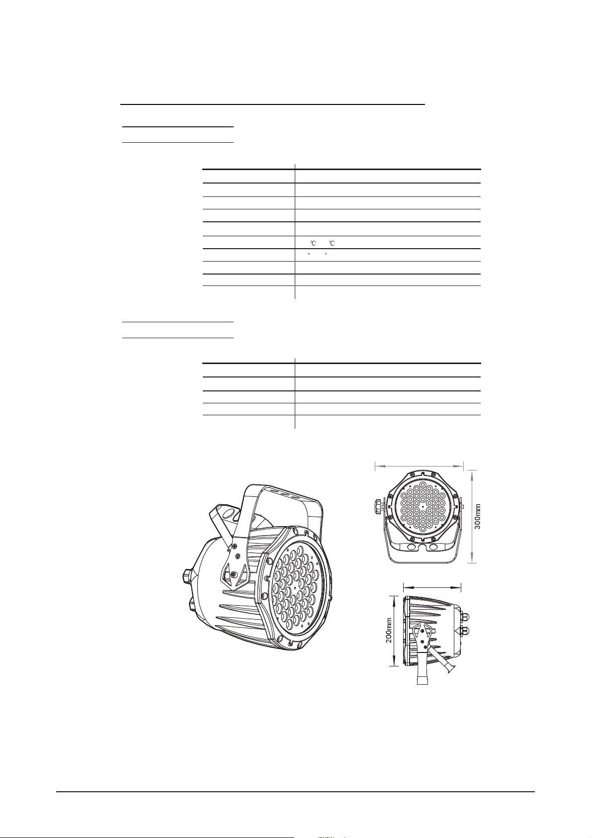
1.3 TECHNICAL SPECIFICATIONS
LED M ODUL E
LED MODULE:
Voltage
Rated Power
LED/Unit
Output/LED
Environment Temperature
LED Beam Angle
Cooling
Dimensions
Weight
CON TROLLER
CONTROLLER:
Voltage
Rated Power
Dimensions
Weight
90~250V...50/60Hz
65W
IP65 protection rating
IP
36pcs (12 xRED / 12x GREEN / 12 x BLUE)
1W
-20 ~40
15 (30 Optional)
Direct air convection
235 x 165 x 300mm
4Kg
220~240V, 50/60Hz......100~120V, 50/60Hz
1.5W
IP33 protection rating
IP
180 x 125 x 49mm
0.7Kg
235mm
165mm
1 PRODUCT(GENERAL) 3
2007.03.10
Page 6

1.4 PHOTOMETRIC DATA
PHO TOMETRI C DATA
WHITE
3
2
1
0
1
2
3
RED
3
2
1
0
1
2
3
GREEN
3
2
1
0
1
2
3
BLUE
3
2
1
0
1
2
3
2750
2(0 .52) 4(1 .05) 6(1.57) 8(2.10)
1145
2(0 .52) 4(1.05) 6(1.57) 8(2.10) 10Distance (m)
1763
2(0 .52) 4(1.05) 6(1.57) 8(2.10) 10Distance (m)
307
2(0 .52) 4(1.05) 6(1.57) 8(2.10) 10Distance (m)
700 320 190 145 LUX
10Distance (m)
(2. 60Diame ter( m))
290 130 72 50 LU X
(2. 60Diame ter( m))
570 27 0 158 128 LUX
(2. 60Diame ter( m))
98 46 27 22 LUX
(2. 60Diame ter( m))
1 PRODUCT(GENERAL) 4
2007.03.10
Page 7
1.5 SAFETY WARNING
IMP ORTA NT
ALWAYS READ THEUSER MANUAL BEFORE OPERATION.
PLEASE CONFIRM THATTHE POWER SUPPLYSTATED ON THE
PRODUCT IS THE SAME AS THEMAINS POWER SUPPLY IN YOUR
AREA.
This productmust be installed by a qualifiedprofessional.
Always operatethe equipment as described in the user manual.
A minimum distance of 0.5m must be maintained between the equipment and
combustible surface.
The product must always be placed in a well ventilated area.
Always make sure that the equipment is installed securely.
DO NOT stand close to the equipment and stare directly into the LED light
source.
Always disconnect the power supply before attempting and maintenance.
Always make sure that the supporting structure is solid and can support the
combined weight ofthe products.
The earth wire must always be connected tothe ground.
Do not touch the power cablesif your handsare wet.
ATT ENT ION
This product leftthe place ofmanufacture in perfectcondition. In order to
maintain this condition and for safeoperation, the user must always follow the
instructions and safety warnings described in this user manual.
Avoid shaking or strong impactsto any partof the equipment.
Make sure that al parts ofthe equipment are kept clean and free of dust.
Always make sure that the power connections are connected correct and
secure.
If there is any malfunction of the equipment, contact yourdistributor
immediately.
When transferring the product,it isadvisable to use the original packagingin
which the productleft thefactory.
Shields, lenses or ultraviolet screens shallbe changed ifthey have become
damaged tosuch an extent thattheir effectiveness is impaired.
The lamp(LED) shall be changed if ithas become damaged orthermally
deformed.
1 PRODUCT(GENERAL) 5
2007.03.10
Page 8

2
INSTALLATION
2.1 MOUNTING
2.2 POWER CONNECTIONS
2.3 SETTING UP WITHA DMX512 CONTROLLER
2.3-1 DMX512 ADDRESSING WITHOUTID ADDRESSING
2.3-2 DMX512 ADDRESSING WITHID ADDRESS
2.4 SETTING UP WITH THE PiX CONTROLLER
2.4-1 SINGLEROW APPLICATION
2.4-2 STANDARD BLOCK APPLICATION
2.4-3 REPEAT ROW BLOCK APPLICATION
2.5 OPERATION: DMX512 Vs PiX CONTROLLER
2 INSTALLATION
6
2007.03.10
Page 9
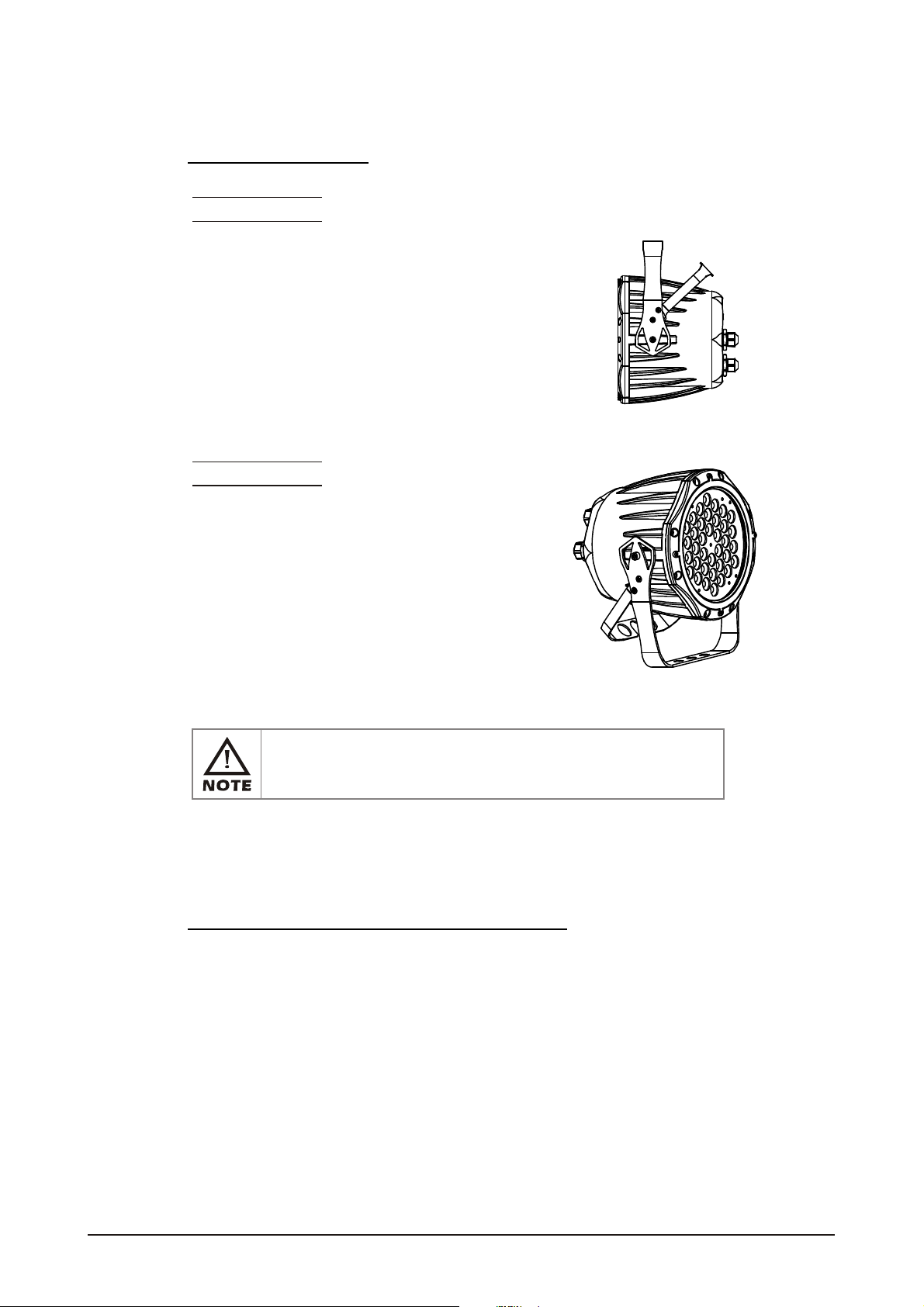
2.1 MOUNTING
HANGING
The LED PAR can be mounted in a hanging position using
the supporting bracket. The bracket should be secured to
the mounting truss or structure using a standard mounting
clamp. Please note that when hanging the unit a safety
cable should also beused.
UPRIGHT
The LED PAR can be mounted in an upright or
sitting position using the supporting brackets.
The LED MODULE can be mountedat any angleand in any
position. It is possible to furtheradjust the angle of the LED
MODULE using thetwo adjustment knobslocated on the side of
the fixture.
2.2 POWER CONNECTIONS
@ 220V:40 units may beconnected in series
@120V: 20units maybe connected in series
2 INSTALLATION
7
2007.03.10
Page 10
2.3 SETTING UP WITH A DMX512
CONTROLLER
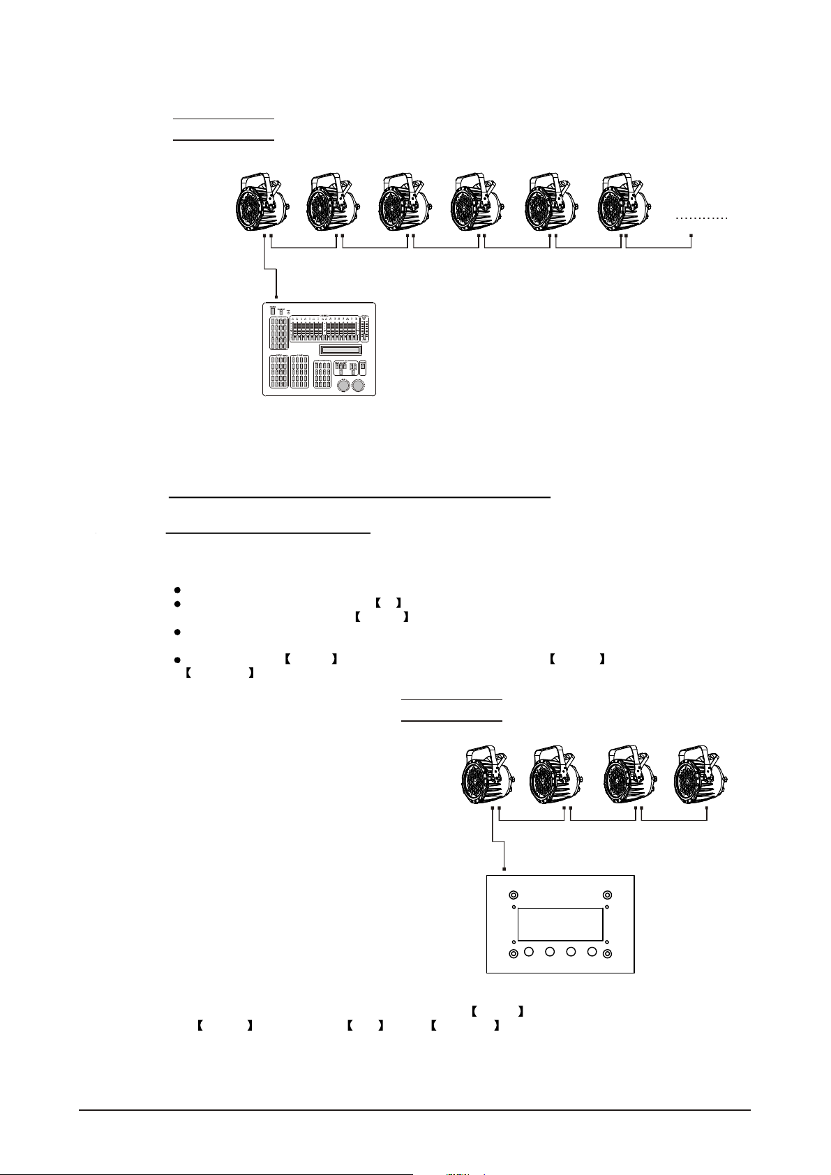
2.3-1 DMX512 ADDRESSING WITHOUT IDADDRESSING
Connect the DMX512 controller to the units in series.
Each unit has 9 DMX channelsso the DMX Addresses should increase by increments of
9 (e.g. 1,10,19,28...)
The ID address has not beenset so therefore when usingthe controller CH8 must
be inactive (CH8=0 ).
Each DMX Address may be used as many times as required.
Any DMX address inthe range from 001 to 500 may be used.
Example:
DMX Addr.1 DMX Addr.10 DMX Addr.19
DMX512
CONTROLLER
The figure above shows a simple DMX512
layout with thestarting address of the first
unit set at 1, with thesecond set at 10 and
so on... (Note that when used in this way,
the CH8 IDfunction must be inactive (CH8=0))
2.3-2 DMX512 ADDRESSING WITH IDADDRESS
Connect the DMX512 controller to the units in series
Each unit has 9 DMX channelsso the DMX Addresses should increase by increments of
9 (e.g. 1,10,19,28...)
Each DMXAddressmay be used as many times as required.
Any DMX address inthe range from 001 to 500 may be used.
Each DMX address may carry upto 66 separateID addresses.
ID should beset in the menu on each unit in ascending values
(i.e. 1,2,3...)
ID addressesare accessible from Ch8on the DMX512 controller.
2 INSTALLATION
8
2007.03.10
Page 11
Example:
DMX Addr.1
ID Addr.1
DMX Addr.1
ID Addr.2
DMX Addr.1
ID Addr.3
DMX Addr.10
ID Addr.1
DMX Addr.10
ID Addr.2
DMX Addr.10
ID Addr.3
DMX512
CONTROLLER
The figure above shows a simple DMX layout
which has used three units at each DMX address.
The three unitshave differentID addresses which
allows the user to collectively control the whole
group ofunits atthat DMX address by setting
CH8 to 0, or to control each unit independently by
first selectingthe DMXaddress and then byusing
CH8 to locatethe target IDaddress.
2.4 SETTING UP WITH THE PiX
CONTROLLER
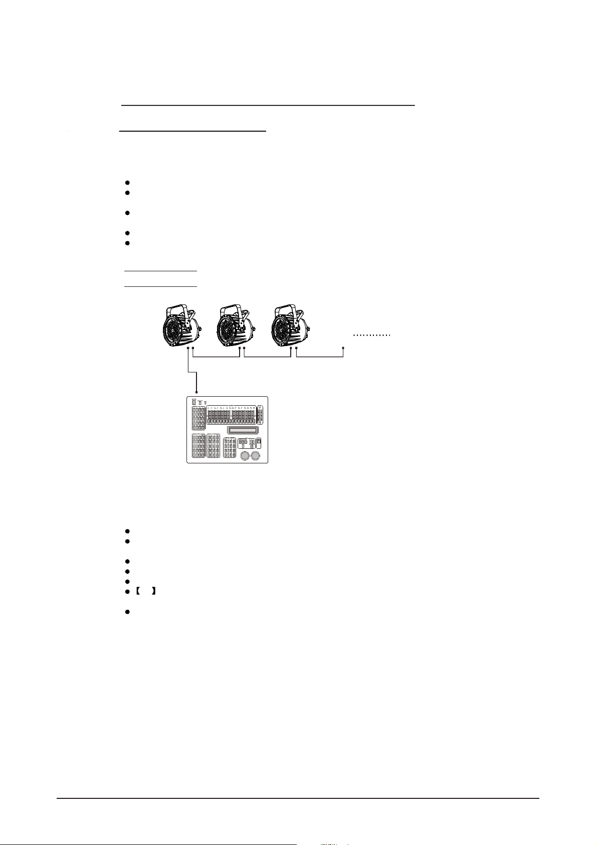
2.4-1 SINGLE ROW APPLICATION
Connect the fixturesto the PIXCONTROLLER in series.
ID Address should be setin the Id menu on each unit in ascendingvalues
(i.e. 1,2,3...Not required for WASH programs).
When using thePIX CONTROLLER with the fixtures there is no need toset the DMX
address.
When usingthe Effect programs it is important to set the Range of fixtures in the
Settings menu of the PIX CONTROLLER.
2 INSTALLATION
Example:
ID Addr.1 ID Addr.2 ID Addr.3 ID Addr.4
CONTROLLER
MOD E SET UP UP DOW N
In the figure above the PIX controller is connected in series to 4 units with corresponding
ID addressesfrom 1 to 4. In order to activate the Effect programs in the PIX CONTROLLER,
the Range must be setto 004 in the Settings menu ofthe PIXCONTROLLER.
9
2007.03.10
Page 12

2.4-2 STANDARD BLOCK APPLICATION
Connect the fixtures to the PIX CONTROLLER in series in the direction that is required.
ID Address should be setin the Id menu on each unit in ascendingvalues
(i.e. 1,2,3...Not required for WASH programs).
When usingthe Effect programs it is important to set the Range of fixtures in the
Settings menu of the PiX CONTROLLER.
Example:
ID Addr.1 ID Addr.2 IDA ddr.3
ID Addr.6ID Addr.5IDA ddr.4
ID Addr.7 ID Addr.8 IDA ddr.9
CONTROLLER
MOD E SET UP U P DO WN
In the figure above the PiX controller is connected in series to 9 units with corresponding
ID addressesfrom 1 to 9. In order to activate the Effect programs in the
PIX CONTROLLER, the Range must be set to 009 in the Settings menu of
the PIX CONTROLLER. (Note: it ispossible to create different kinds ofeffects by changing
the direction andposition of IDAddresses)
2 INSTALLATION
10
2007.03.10
Page 13

2.4-3 REPEAT ROW BLOCK APPLICATION
Connect the fixturesto the PIX CONTROLLER inseries.
ID Address should be set in the Id menu on each unit in ascendingorder with
each row repeated (Not required for Wash programs).
When using thePRO-a CONTROLLER withthe fixtures there is noneed to setthe DMX
address.
When usingthe Effect programs itis important to setthe Range of fixturesin the
Settings menu ofthe PixCONTROLLER.
Example:
ID Addr.1 ID Addr.2 ID Addr. 3
ID Addr.3ID Addr.2ID Addr.1
ID Addr.1 ID Addr.2 ID Addr. 3
CONTROLLER
MODE SE TUP UP DOW N
In the figure above the PIX controller is connected in series to 9 fixtures with each row comprising
of 3 fixtureswith corresponding IDaddresses from 1to 3. Eachrow is repeatedso that theID
addresses appear the same was asthe first row. In order to activate the Effect programs in
the PIX CONTROLLER, the Range must be setto 003 in the Settings menu ofthe
PIX CONTROLLER.
2 INSTALLATION
11
2007.03.10
Page 14

2.5 OPERATION: DMX512 Vs PiX
CONTROLLER
OPERATION WITH ADMX512 CONTROLLER
DMX512 ADDRESS
ID ADDRESS
DMX512 ADDRESS
ID ADDRESS
DMX512 ADDRESS
ID ADDRESS
DMX512 ADDRESS
ID ADDRESS
X
X
X
X
AVAILABLE
FUNCTIONS
Basic WASH
Programming
Advanced
WASH &
EFFECT
programming
Basic WASH
programming
Advanced
WASH &
EFFECT
programming
BENEFITS DRAWBACKS
No need to set
up DMX Address
or IDAddress
Units are fully controlled
from DMX512 controller
DMX Address
ID address allowsfor
less DMX channels
when programming*
Advanced fixture
mapping
OPERATION WITH THE PiX CONTROLLER
AVAILABLE
FUNCTIONS
BENEFITS DRAWBACKS
Must locate
previosly stored
DMX Address
Programming requires
many DMX channels
All ID addresses
must be set
All ID addressesmust
be set
2 INSTALLATION
DMX512 ADDRESS
ID ADDRESS
DMX512 ADDRESS
ID ADDRESS
DMX512 ADDRESS
ID ADDRESS
DMX512 ADDRESS
ID ADDRESS
Play WASH auto
X
programs, Basic
CUSTOM
programming &
X
Schedule play
Play WASH auto
programs, Basic
CUSTOM
programming &
X
Schedule play
Play WASH &
X
EFFECT auto
programs, Advanced
CUSTOM
programming &
Schedule play
Play WASH &
EFFECT auto
programs, Advanced
CUSTOM
programming &
Schedule play
12
No need to set up
DMX Address or
ID Address
DMX address not used
DMXAddress not used
Controlspeedandtimeof
all WASH &
EFFECT programs
Createpowerful
CUSTOM programs
Schedule play
Triggerautoprograms with
DMXIN
DMXAddress not used
Controlspeedandtimeof
all WASH &
EFFECT programs
Createpowerful
CUSTOM programs
Schedule play
Triggerautoprograms with
DMXIN
Only control ofall
units at thesame time
Only control ofall units
at the sametime
All ID Addresses
must be set
All ID Addresses
must be set
2007.03.10
Page 15

3
DISPLAY PANEL OPERATION
3.1 BASIC
3.2 MENU
3.3 ACTIVATING AUTO PROGRAMS
3.4 DMX512SETTINGS
3.5 ID ADDRESS
3.6 EDITING CUSTOM PROGRAMS
3.7 SPECIAL SETTINGS
3.8 ACTIVATE THE PASSWORD
3.9 RGB CHANNEL MODEL
3 DISPLAY PANEL OPERATION
13
2007.03.10
Page 16

3.1 BASIC
The LED fixtureis mounted witha LCD display and 4 controlbuttons.
MENU SET UP
POWE RO UTPOWE RI N
DMX IN DMX OU T
UPSET DOWNMENU
DOWN
scroll through the mainmenu or return tothe main menu
enter the currently selected menu orconfirm thecurrent function value
scroll 'UP' through the menulist or increase the valueof the current function
scroll'DOWN'through themenulist or decrease thevalue ofthe currentfunction
3 DISPLAY PANEL OPERATION
14
2007.03.10
Page 17

3.2 MENU
MENU
AUTO AT.01
dMX
Id
Edit
SET UPLd
AT.02
AT.10
PR.C1
PR.C2
PR.C10
d 001 512
I 001 IO66
PR.C1
PR.C2
PR.C3
PR.C4
PR.C5
PR.C6
PR.C7
PR.C8
PR.C9
PR.C10
SC.01
SC.02
SC.30
rEd
GrEn
bluE
Strb
TInE
FAdE
R. 0 255
G. 0 255
B. 0 255
S. 0 255
T. 0 255
F. 0 255
PAS S
ARC
REST
On
OFF
RGb
PASS
PASS
***
***
Send
En d
rEST
3 DISPLAY PANEL OPERATION
15
2007.03.10
Page 18

3.3 ACTIVATING AUTO PROGRAMS
MENU
Auto
Select the target[Auto] program andpress SET
Programs AT.01 to AT.10 are fully pre-programmed andwill not be altered
by changes in EdIT mode
Programs PR.C1 to PR.10 are fully pre-programmed andcan be edited
in EdIT mode
AUTO AT.01
3.4 DMX512 SETTINGS
AT.02
AT.10
PR.C1
PR.C2
PR.C10
MENU
dMX
dMX
Enter the dMX mode to setthe DMX ADDRESS.
d 001 512
3 DISPLAY PANEL OPERATION
16
2007.03.10
Page 19

3.5 ID ADDRESS
MENU
Id
I 001 IO66
Id
Enter the Id mode to setthe IDADDRESS
3.6 EDITING CUSTOM PROGRAMS
MENU
Edit
EdIT
PR.C1
PR.C2
PR.C3
PR.C4
PR.C5
PR.C6
PR.C7
PR.C8
PR.C9
PR.C10
SC.01
SC.02
SC.30
rEd
GrEn
bluE
Strb
TInE
FAdE
R. 0 255
G. 0 255
B. 0 255
S. 0 255
T. 0 255
F. 0 255
Enter the EdIT mode to edit the customprograms PR.C1 to PR.10
Each custom program has 30 stepsthat can be edited
Each step allowsthe creation ofa scene using RED rED , GREEN GrEn ,
BLUE bLUE , STROBE STrB , TIME TInE & FADE FAdE
3 DISPLAY PANEL OPERATION
17
2007.03.10
Page 20

3.7 SPECIAL SETTINGS
MENU
SET
Select UPLd to upload thecustom programs from the current MASTERunit to
the SLAVE units.
In order to activate the upload function thepassword mustbe entered
Password is thesame as the main access password
When uploading the MASTER and SLAVE units willdisplay YELLOW
If an error occurs whenuploading the MASTERand/or SLAVE units will display RED
On successful uploadingof the customprograms the MASTER and SLAVE units
will display GREEN.
In order toreset custom modesto default valuesselect rEST
SET UPLd
PASS
REST
PASS
3.8 A CTIVATE THE PASSWORD
***
***
Send
En d
rEST
MENU
PASS
PASS
Enter the PASS mode to selectwhether the accesspassword is onor off.
In order toenter access passwordit is necessaryto first press SET
Accesspassword is UP + DOWN + UP + DOWN
On
OFF
3.9 RGB CHANNEL MODEL
MENU
ARC
RGb
Enter the RGb mode, the DMX512 only receive 3channels' signal, thesequence
is channel 1 RED (0~255), channel 2 GREEN (0~255) , channel 3 BLUE
(0~255).
RGb
3 DISPLAY PANEL OPERATION
18
2007.03.10
Page 21

4
USING A DMX512
CONTROLLER
4.1 BASIC ADDRESSING
4.2 CHANNELASSIGNMENT
4.3 BASIC INSTRUCTIONS FOR DMX512
OPERATION
4 USING A DMX512CONTROLLER
19
2007.03.10
Page 22

4.1 BASIC ADDRESSING
Connect all of the unitsin series using standard DMX512signal cable or the IP65rated cable
provided.
Set the DMX512 addressin the DMX menu.
It is possible tohave the same DMX address orindependent addressesfor each fixture.
4.2 CHANNELASSIGNMENT
DMX M ODE
CHANNEL FUNCTIONVALUE
1
2
3
4
5
6
0 255
0 255
0 255
0 255
0 9
10 29
30 39
40 49
50 69
70 79
80 89
90 109
110 119
120 129
130 149
150 159
160 169
170 189
190 199
200 219
220 229
230 249
250 255
0 9
10 63
64 127
128 191
192 255
MASTER DIMMER
RED
(or STEP TIMEwhen PR.01-PR.10 is activated)
GREEN
(or FADETIME when PR.01-PR.10is activated)
BLUE
NO FUNCTION
RED
RED(85%)+YELLOW(15%)
RED(60%)+YELLOW(40%)
YELLOW
YELLOW(85%)+GREEN(15%)
YELLOW(60%)+GREEN(40%)
GREEN
GREEN(85%)+BLUE(15%)
GREEN(60%)+BLUE(40%)
BLUE
BLUE(85%)+CYAN(15%)
BLUE(60%)+CYAN(40%)
CYAN
CYAN(50%)+PURPLE(50%)
PURPLE
PURPLE(50%)+WHITE(50%)
WHITE(95%)+YELLOW(5%)
WHITE
NO FUNCTION
STROBE 1
STROBE 2
STROBE 3
STROBE 4
4 USING A DMX512CONTROLLER
20
2007.03.10
Page 23

CHANNEL FUNCTIONVALUE
0 9
10 19
20 29
30 39
40 49
50 59
60 69
70 79
80 89
90 99
100 109
7
110 119
120 129
130 139
140 149
150 159
160 169
170 179
180 189
190 199
200 255
0 9
10 19
20 29
30 39
40 49
50 59
60 69
70 79
80 89
90 99
100 109
110 119
120 129
130 139
140 149
8
150 159
160 169
170 179
180 189
190 199
200 209
NO FUNCTION
AT. 01 ( AUTO 01)
AT.02
AT.03
AT.04
AT.05
AT.06
AT.07
AT.08
AT.09
AT. 101 (AT.01 to AT.09 cycle 5min each AUTOmode)
PR.C1 (CUSTOM PROGRAM1)
PR.C2
PR.C3
PR.C4
PR.C5
PR.C6
PR.C7
PR.C8
PR.C9
PR.10
ID ADDRESS
ID1~ID66
ID1
ID2
ID3
ID4
ID5
ID6
ID7
ID8
ID9
ID10
ID11
ID12
ID13
ID14
ID15
ID16
ID17
ID18
ID19
ID20
4 USING A DMX512CONTROLLER
21
2007.03.10
Page 24

8
9
VALUECHANNEL FUNCTION
210
211
212
213
214
215
216
217
218
219
220
221
222
223
224
225
226
227
228
229
230
231
232
233
234
235
236
237
238
239
240
241
242
243
244
245
246
247
248
249
250
251
252
253
254
255
0 250
251 255
ID21
ID22
ID23
ID24
ID25
ID26
ID27
ID28
ID29
ID30
ID31
ID32
ID33
ID34
ID35
ID36
ID37
ID38
ID39
ID40
ID41
ID42
ID43
ID44
ID45
ID46
ID47
ID48
ID49
ID50
ID51
ID52
ID53
ID54
ID55
ID56
ID57
ID58
ID59
ID60
ID61
ID62
ID63
ID64
ID65
ID66
CH1, CH2, CH3& CH4 INSTANT FADER RESPONSE
CH1, CH2, CH3& CH4 DELAY FADERRESPONSE
4 USING A DMX512CONTROLLER
22
2007.03.10
Page 25

4.3 BASIC INSTRUCTIONS FOR DMX512
OPERATION
MASTER DIMMER
CH1 controlsthe intensity of the currently projected color
When the slider is at thehighest position (255) the intensity of the output is themaximum
RED, GREEN & BLUE COLOR SELECTION
CH2, CH3 & CH4 control theintensity ratio ofeach of theRED, GREEN &BLUE LEDs.
When the slideris at the highest position(255) the intensity of the color is themaximum.
CH2, CH3 & CH4 can becombined together tocreate over 16million colors.
CH2, CH3& CH4 have priority over CH4, CH5, CH6 & CH7
COLOR MACROS
CH5 selects the requiredCOLOR MACRO
CH5 has priority over CH2, CH3and CH4
CH1 is used to control theintensity of the COLOR MACRO
STROBE
CH 6 controls thestrobe of CH1 to CH5
Strobe 1is with RGB in-step
Strobe 2is with RGB out-step
Strobe 3 isa pulse strobe(slow on/fast off)
Strobe 4 isa pulse strobe(fast on/slow off)
ID ADDRESSSELECTION
CH8 is used to select thetarget ID address.
Each independent DMX address may haveupto 66 independent ID addresses.
An IDaddress of 0will activate allID address locations.
AUTO
CH7 selects the presetAUTO programs AT.01-AT10 or the custom AUTO programs PR.C1-
PR.10
When activating the custom AUTO programs PR.C1to PR.10 then it is possible to control the
STEP TIMEand FADE TIMEusing CH2 and CH3 respectively.
CH9 is used to select whether the unit operates with an instant response to the DMX fader or
whether there is a preset delay response.
4 USING A DMX512CONTROLLER
23
2007.03.10
Page 26

5
USING THE CONTROLLER
5.1 MENU
5.2 WASH PROGRAM
5.3 EFFECTPROGRAM
5.4 CUSTOM PROGRAM
5.5 PLAY SCHEDULE
5.6 CLOCK
5.7 SCHEDULE
5.8 SETTINGS
5.9 ACTIVATE THE PASSWORD
5.10 PiXCONTROLLER EXTERNAL
CONTROL VIA DMX512
5.11 MAINTENANCE
5 USING THE CONTROLLER
24
2007.03.10
Page 27

5.1 MENU
MENU
Washprogram Wash 1
Wash 2
Wash 8
Effect program Effect 1
Effect 2
Effect 8
Custom program
Custom 1
Custom 1
Edit
Scene 1
Scene 2
Scene 100
Wash 1
Edit
Wash 2
Edit
Wash 8
Edit
Effect 1
Edit
Effect 2
Edit
Effect 8
Edit
Scene 1
IDaddress
Scene 1
Steptime
Scene 1
Fadetime
Scene 1
Red
Scene 1
Green
Scene 1
Blue
Scene 1
Module
Scene 1
Strobe
Step time 001
Fadetime 001
Step time 001
Fadetime 001
Step time 001
Fadetime 001
Speed 001
Speed 001
Speed 001
Scene 1
IDaddress
Scene 1
Module 001
Scene 1
Red 001
Scene 1
Green 001
Scene 1
Blue 001
Scene 1
Strobe 001
Scene 1
Steptime 001
Scene 1
Fadetime 001
5 USING THE CONTROLLER
Playschedule
Clock Time now
Schedule
>>>
Edittime
25
02/08/2006
13:50:24
02/08/2006
13:50:24
2007.03.10
Page 28

Schedule
Wash 1
00:00>>>00:00
Wash 2
00:00>>>00:00
Start >>> End
00:00>>>00:00
Start >>> End
00:00>>>00:00
Wash 8
00:00>>>00:00
Effect 1
00:00>>>00:00
Effect 2
00:00>>>00:00
Effect 8
00:00>>>00:00
Custom 1
00:00>>>00:00
Custom 2
00:00>>>00:00
Custom 8
00:00>>>00:00
Settings DMXaddress
Range
Allow edit
Detect device
Start >>> End
00:00>>>00:00
Start >>> End
00:00>>>00:00
Start >>> End
00:00>>>00:00
Start >>> End
00:00>>>00:00
Start >>> End
00:00>>>00:00
Start >>> End
00:00>>>00:00
Start >>> End
00:00>>>00:00
DMXaddress
001
Range
001
Allow edit
YES NO
>>>
Reset to
Factorysettings
Password PasswordON/OFF
Setpassword
Reset
YES NO
Password
ON/OFF
SetPassword
5 USING THE CONTROLLER
26
2007.03.10
Page 29

5.2 WASH PROGRAM
MENU
Washprogram Wash 1
Wash
Select from the eight Wash programs andinstantly play
When Edit is allowedin [Settings]it is possible to set the Step time
and Fade time
The unitof Step time is 5 seconds and can be adjusted from1 to 255
The unitof Fade time is 5seconds and can be adjusted from 1 to 255
5.3 EFFECT PROGRAM
MENU
Effect program Effect 1
Wash 2
Wash 8
Effect 2
Wash 1
Edit
Wash 2
Edit
Wash 8
Edit
Effect 1
Edit
Effect 2
Edit
Step time 001
Fadetime 001
Step time 001
Fadetime 001
Step time 001
Fadetime 001
Speed 001
Speed 001
Effect 8
Effect 8
Edit
Speed 001
Effect
Select from the eight Effect programs andinstantly play
When Edit is allowedin Settings it ispossible toset the Speed
The Speed of the Effect can be adjusted from 1 to 255
5 USING THE CONTROLLER
27
2007.03.10
Page 30

5.4 CUSTOM PROGRAM
MENU
Custom program
Custom 1
Custom 1
Edit
Scene 1
Scene 2
Scene 100
Scene 1
IDaddress
Scene 1
Step time
Scene 1
Fadetime
Scene 1
Red
Scene 1
Green
Scene 1
Blue
Scene 1
Module
Scene 1
Strobe
Scene 1
ID address
Scene 1
Module 001
Scene 1
Red 001
Scene 1
Green 001
Scene 1
Blue 001
Scene 1
Strobe 001
Scene 1
Step time 001
Scene 1
Fade time 001
Custom
Select from the eight Custom programs and instantly play
When Edit is allowedin Settings it ispossible toenter theedit section
Scene
Select from 100 scenesto createor edit
Scenes that are not required should have the Step time set as0
ID address
Select theID address of thetarget unit
Set the ID address as 0 to include all ID addresses
ID address action from previous steps is stored until changed allowing for
combination colors/effects using differentID addresses
Module
Select the[Module] to be active:
0=#1 #2 #3
1=#1
2=#2
3=#3
4=#1 #2
5=#2 #3
6=#1 #3
Red , Green & Blue
Combine RED,GREEN &Blue to create an infinite range of colors (0-255)
Strobe
Select thestrobe speed from 0-20Hz
Step time
Select the Step time of the current scene
The unitof Step time is 0.1s for the range 0-10 and 1 sec forthe range11-255
5 USING THE CONTROLLER
Fade time
Select the[Fade time] of thecurrent scene
The unitof [Fade time] is 1 second and can be adjusted from 0to 255
28
2007.03.10
Page 31

5.5 PLAY SCHEDULE
MENU
Schedule
Activate this menu in order to play the schedule
5.6 CLOCK
MENU
Time now
Enter this function to view the current time.
Edit time
Enter this menu to edit the date and time.
Playschedule
Clock Time now
Schedule
>>>
Edittime
02/08/2006
13:50:24
02/08/2006
13:50:24
5.7 SCHEDULE
MENU
Schedule
Wash 1
00:00>>>00:00
Wash 2
00:00>>>00:00
Wash 8
00:00>>>00:00
Effect 1
00:00>>>00:00
Effect 2
00:00>>>00:00
Effect 8
00:00>>>00:00
Custom 1
00:00>>>00:00
Custom 2
00:00>>>00:00
Start >>> End
00:00>>>00:00
Start >>> End
00:00>>>00:00
Start >>> End
00:00>>>00:00
Start >>> End
00:00>>>00:00
Start >>> End
00:00>>>00:00
Start >>> End
00:00>>>00:00
Start >>> End
00:00>>>00:00
Start >>> End
00:00>>>00:00
5 USING THE CONTROLLER
29
Custom 8
00:00>>>00:00
Start >>> End
00:00>>>00:00
2007.03.10
Page 32

Wash , Effect & Custom
Enter each of the twenty-four Wash , Effect and Custom programs to
set Start & End time
Programs will be played according to schedule time order.
When a program is currently playing and has not yet reached the [End] time, any
new [Start] time will have priority when over-lapping times.
5.8 SETTINGS
MENU
Settings DMXaddress
Range
Allow edit
Detect device
Reset to
Factorysettings
DMXaddress
001
Range
001
Allow edit
YES NO
>>>
Reset
YES NO
DMX address
Enter the DMX address menu toset theDMX address of the controller.
The DMX address may only be selected in the range 1-250
Range
Enter the numberof units connected together in series.
Allow edit
This functionallows or disables editin Wash program ,
Effect program & Custom program
Detect device
This functionenables the controller to connect toall units.
When new units are attached, thisfunction must beused to locatenew units.
When the controlleris turned off and thenon again, the controller will also
detect new units.
5 USING THE CONTROLLER
Reset to factorysettings
This functions will resetall settings to the original factory setting.
Note that Custom program settings will not be affected by this function
Default settings
Schedule all times in theschedule are reset to 00:00
Wash program step timesand fade times are reset to 001
Effect program speeds are reset to 001
DMX address DMX address is resetto 001
Range range isreset to 066
Allow edit allow editis reset to Yes
Password ON/OFF password is reset to OFF
Set password password is reset to 00000000 ('DOWN’ = 0, 'UP'= 1)
30
2007.03.10
Page 33

5.9 ACTIVATE THE PASSWORD
MENU
Password
ON/OF F
SetPassword
Password
ON/OFF
Password
Enter the Password mode to set passwordYES/NO
When password is activated, displaywill demand password each time
the fixture is powered on.
Enter the Set password menu to change password.
Set new password using the UP & DOWN keys.
Input an 8 digit passwordand then press SET to confirm
NOTE: In the event thatthe password is forgotten. Please use the factory password shown below.
UP > DOWN > UP > DOWN > Up >UP > DOWN > DOWN
5.10 PiX CONTROLLER EXTERNAL
CONTROL VIADMX512
It is possible toaccess the internal programs of the PiX controller using a DMX512 controller.
The diagram below shows how toconnect the equipment together.
It is necessary toset the DMX address on the controller to the target
DMX address as selected on theDMX512 controller
5 USING THE CONTROLLER
DMX512
CONTROLLER
CONTROLLER
MOD E SE TUP U P DO WN
31
2007.03.10
Page 34

CHANNEL VALUE FUNCTION
Refresh
Wash 1
Refresh
Wash 2
Refresh
Wash 3
Refresh
Wash 4
Refresh
Wash 5
Refresh
Wash 6
Refresh
Wash 7
Refresh
Wash 8
Refresh
Effect 1
Refresh
Effect 2
Refresh
Effect 3
Refresh
Effect 4
Refresh
Effect 5
1
2
0 10
11 30
31 40
41 60
61 70
71 90
91 100
101 120
121 130
131 150
151 160
161 180
181 190
191 210
211 220
221 255
0 10
11 30
31 40
41 60
61 70
71 90
91 100
101 120
121 130
131 150
CHANNEL VALUE FUNCTION
Refresh
Effect 6
Refresh
Effect 7
Refresh
Effect 8
Refresh
Custom 1
Refresh
Custom 2
Refresh
Custom 3
Refresh
Custom 4
Refresh
Custom 5
Refresh
Custom 6
Refresh
Custom 7
Refresh
Custom 8
OFF
ON
2
3
4
151 160
161 180
181 190
191 210
211 220
221 255
0 10
11 30
31 40
41 60
61 70
71 90
91 100
101 120
121 130
131 150
151 160
161 180
181 190
191 210
211 220
221 255
0 127
128 255
5 USING THE CONTROLLER
32
2007.03.10
Page 35

5.11 MAINTENANCE
ITEM
No
1
Gel holder
2
Upper cover
3
Glass plate
4
LED heat-transfer plate
5
Power supply
6
Display board
7
Casing
Driver board
8
Secondary support
9
Main support
10
5
6
7
1
2
3
4
8
10
9
5 USING THE CONTROLLER
33
2007.03.10
 Loading...