

Page 1

USER
MANUAL
Ver 1,0 (firmware V12)
Page 2

T
ABLE OF CONTENTS
TABLE OF CONTENTS..................................................................I.
PART 1 PRODUCT (GENERAL)....................................................1.
PART 2 INSTALLATION...............................................................6.
PART 3 DISPLAY PANEL OPERATION.......................................15.
1.1--PRODUCT INTRODUCTION.........................................................2.
1.2--PRODUCT FEATURES.................................................................2.
1.3--TECHNICAL SPECIFICATIONS.....................................................3.
1.4--PHOTOMETRIC DATA..................................................................4.
1.5--SAFETY WARNING......................................................................5.
2.1--MOUNTING...................................................................................7.
2.2--POWER CONNECTION..................................................................7.
2.3--INTERLOCKING MULTIPLE FIXTURES...........................................8.
2.4--SETTING UP WITH A DMX512 CONTROLLER.................................9.
2.4-1--DMX512 ADDRESSING WITHOUT ID ADDRESSING(STAGE 1 MODE)...........9.
2.4-2--DMX512 ADDRESSING WITH ID ADDRESS(STAGE 1 MODE).......................9.
2.4-3--ADAS WITH ID ADDRESS(STAGE 1 MODE)................................................10.
2.5--SETTING UP WITH THE PiX CONTROLLER.................................11.
2.5-1--SINGLE ROW APPLICATION.......................................................................11.
2.5-2--STANDARD BLOCK APPLICATION..............................................................12.
2.5-3--REPEAT ROW BLOCK APPLICATION...........................................................12.
2.6--OPERATION WITH DMX512 Vs PiX CONTROLLER.......................14.
3.1--BASIC........................................................................................16.
3.2--MENU........................................................................................17.
3.3--CREATING A STATIC COLOR......................................................18.
3.4--DMX512 SETTINGS....................................................................18.
3.5--ACTIVATINGAN AUTO PROGRAM..............................................19.
3.6--CHANGING THE SETTINGS........................................................19.
3.7--ACTIVATE THE PASSWORD.......................................................20.
3.8--POWER ON/OFF.........................................................................20.
PART 4 USING A DMX512 CONTROLLER....................................21.
4.1--BASIC ADDRESSING.................................................................22.
4.2--CHANNEL ASSIGNMENT............................................................22.
4.3--BASIC INSTRUCTIONS FOR DMX512 OPERATION......................32.
4.4--PROGRAMMING WITH A DMX512 CONTROLLER: EXAMPLES.....36.
PART 5 USING THE CONTROLLER.............................................40.
5.1--BASIC.......................................................................................41.
5.2--SETTING UP.............................................................................41.
5.3--MENU.......................................................................................42.
5.3--MENU.......................................................................................42.
5.4--WASH PROGRAM......................................................................44.
5.5--EFFECT PROGRAM..................................................................44.
5.6--CUSTOM PROGRAM.................................................................45.
5.7--PLAY SCHEDULE......................................................................46.
5.8--CLOCK.....................................................................................46.
5.9--SCHEDULE...............................................................................46.
5.10--SETTINGS..............................................................................47.
5.11--ACTIVATE THE PASSWORD.....................................................48.
5.12--PIX CONTROLLER EXTERNAL CONTROL VIA DMX512.............48.
PART 6 TROUBLE SHOOTING....................................................50.
TABLE OF CONTENTS I
2007.9.8
Page 3

1
PRODUCT (GENERAL)
1.1 PRODUCT INTRODUCTION
1.2 PRODUCT FEATURES
1.3 TECHNICAL SPECIFICATIONS
1.4 PHOTOMETRIC DATA
1.5 SAFETYWARNING
1 PRODUCT(GENERAL) 1
2007.9.8
Page 4

1.1 PRODUCT INTRODUCTION
This product is designed for indoor or outdoor use. Suitable applications include wash or
effect lighting for architectural, stage or nightclub applications. This product can also be
installed for use in signage and advertising using the dynamic functions available with
DMX512 control. Direct input of DMX512 signal allows the units to be controlled from any
DMX512 controller. This product can be operated as a single unit or in multiple units for
large applications.
The specially developed controller that allows the product to be controlled independent of
the DMX512 controllerenables the userto create and edit a wide range of customprograms.
All programs can be touch-button displayed or scheduled to START and END at scheduled
times. When programs have been created or edited in the controller, it is also possible to
trigger these programs using the DMX IN function when connected to aDMX512 controller.
1.2 PRODUCT FEATURES
LED FIXTURE
* RGB Dimmer 0-100%
* Strobe
* Individual control of each LED group
* Automatic programs
* IP65 protection rating
* LCD display
* Display control 'lock-out'
* Direct DMX512 input
* Automatic DMX512 Addressing
* Independant ID address
* Lightweightaluminium casing
* Black anti-UV plastic cover
* Interlocking-module system
PiX C ONTROLLE R
* RGB Dimmer 0-100%
* Strobe
* Clock & Timer
* Automatic programs (wash & effect)
* Custom programs
* Program Schedule
* LCD display
* Display control 'lock-out'
* Direct DMX512 input
* Lightweightplastic casing
1 PRODUCT(GENERAL) 2
2007.9.8
Page 5
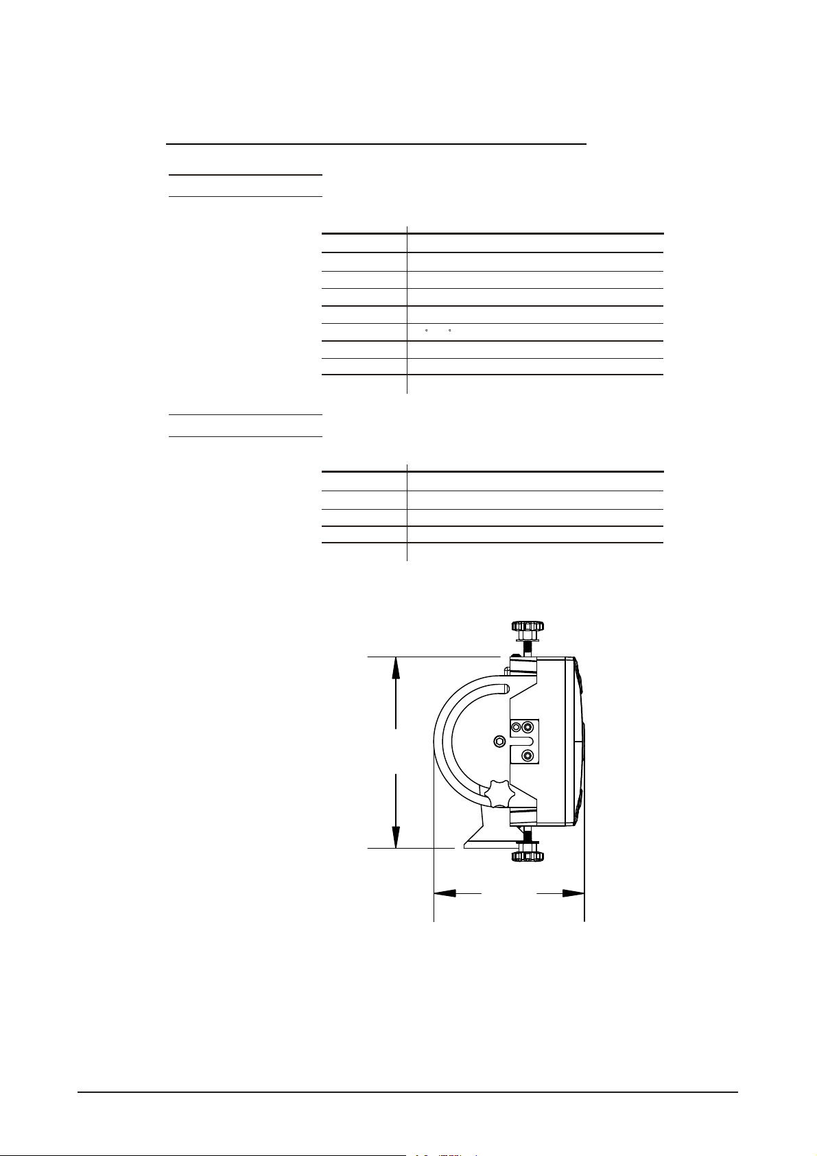
1.3 TECHNICAL SPECIFICATIONS
LED MODUL E
LED MODULE:
Voltage
Rated Power
LED/Unit
Output/LED
LED Beam Angle
Cooling
Dimensions
Weight
CONTR OLLER
CONTROLLER:
Voltage
Rated Power
Dimensions
Weight
90~250V...50/60Hz
80W
IP65 protection rating
IP
54pcs (18 xRED / 18x GREEN /18 x BLUE)
1W
15 (30 Optional)
Direct air convection
570 x 210x 190mm
8.2Kg
220~240V, 50/60Hz......100~120V, 50/60Hz
1.5W
IP33 protection rating
IP
180 x 125x 49mm
0.7Kg
215MM
1 PRODUCT(GENERAL) 3
169MM
2007.9.8
Page 6
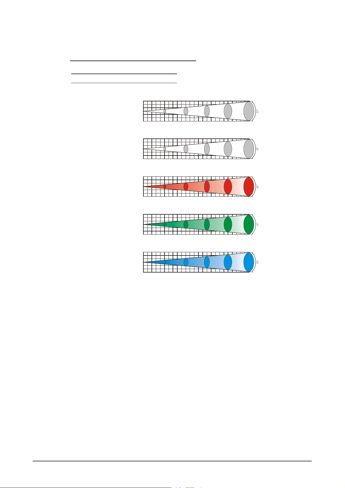
1.4 PHOTOMETRIC DATA
PHOT OMETRIC DATA
RGB 100%
3
2
1
0
1
2
3
2(0 .9x 0.5) 4(1 .4x 1.0) 6(2 .0x 1.6) 8(2 .5x 2.1) 10(3.0 x2.6Area (m) )
WHITE
3
2
1
0
1
2
3
2(0 .9x 0.5) 4(1 .4x 1.0) 6(2 .0x 1.6) 8(2 .5x 2.1) 10(3.0 x2.6Area (m) )
RED
3
2
1
0
1
2
3
2(0 .9x 0.5) 4(1 .4x 1.0) 6(2 .0x 1.6) 8(2 .5x 2.1) 10(3.0 x2.6Area (m) )
GREEN
3
2
1
0
1
2
3
2(0 .9x 0.5)
BLUE
3
2
1
0
1
2
3
2(0 .9x 0.5) 4(1 .4x 1.0) 6(2 .0x 1.6) 8(2 .5x 2.1) 10(3.0 x2.6Area (m) )
2970 950 450 266 218 LUX
Diameter(m)
2370
1130
1763
307 98 46 27 22 LUX
788 375 222 177 LUX
360 167 97 78 LUX
570 270 159 128 LUX
4(1 .4x 1.0)
6(2 .0x 1.6) 8(2 .5x 2.1) 10(3.0 x2.6Area (m) )
Diameter(m)
Diameter(m)
Diameter(m)
Diameter(m)
1 PRODUCT(GENERAL) 4
2007.9.8
Page 7
1.5 SAFETY WARNING
IMPORTANT
ALWAYS READ THE USER MANUAL BEFORE OPERATION.
PLEASE CONFIRM THAT THE POWER SUPPLYSTATED ON THE
PRODUCT IS THE SAME AS THE MAINS POWER SUPPLYIN YOUR
AREA.
This product must be installed by a qualifiedprofessional.
Always operate the equipment as describedin the user manual.
A minimum distance of 0.5m must be maintained between the equipment and
combustible surface.
The product must always be placed in awell ventilated area.
Always make sure that the equipment is installed securely.
DO NOT stand close to the equipment and stare directly into the LED light
source.
Always disconnect the power supply before attempting and maintenance.
Always make sure that the supporting structure is solid and can support the
combined weight ofthe products.
The earth wire must always be connected to the ground.
Do not touchthe power cables if your handsare wet.
ATTENTION
This product left the place ofmanufacture in perfect condition. In order to
maintain this condition and for safe operation, the user must always follow the
instructions and safety warnings described in this user manual.
Avoid shaking or strong impactsto any part of the equipment.
Make sure that al parts ofthe equipment are kept clean and free of dust.
Always make sure that the power connections areconnected correct and
secure.
If there is any malfunction of the equipment, contact your distributor
immediately.
When transferring the product, it is advisable to use the original packaging in
which the productleft the factory.
Shields, lenses orultraviolet screens shallbe changed ifthey have become
damaged to such an extent that their effectiveness is impaired.
The lamp (LED) shall be changed if ithas become damaged or thermally
deformed.
1 PRODUCT(GENERAL) 5
2007.9.8
Page 8

2
INSTALLATION
2.1 MOUNTING
2.2 POWER CONNECTION
2.3 INTERLOCKING MULTIPLE FIXTURES
2.4 SETTING UP WITH A DMX512 CONTROLLER
2.4-1 DMX512 ADDRESSING WITHOUTID ADDRESSING(STAGE 1
MODE)
2.4-2 DMX512 ADDRESSING WITH ID ADDRESS(STAGE 1 MODE)
2.4-3 ADAS WITH ID ADDRESS(STAGE 1 MODE)
2.5 SETTING UP WITH THE PiX CONTROLLER
2.5-1 SINGLE ROW APPLICATION
2.5-2 STANDARD BLOCK APPLICATION
2.5-3 REPEAT ROW BLOCK APPLICATION
2.6 OPERATION: DMX512Vs PiX CONTROLLER
2 INSTALLATION 6
2007.9.8
Page 9
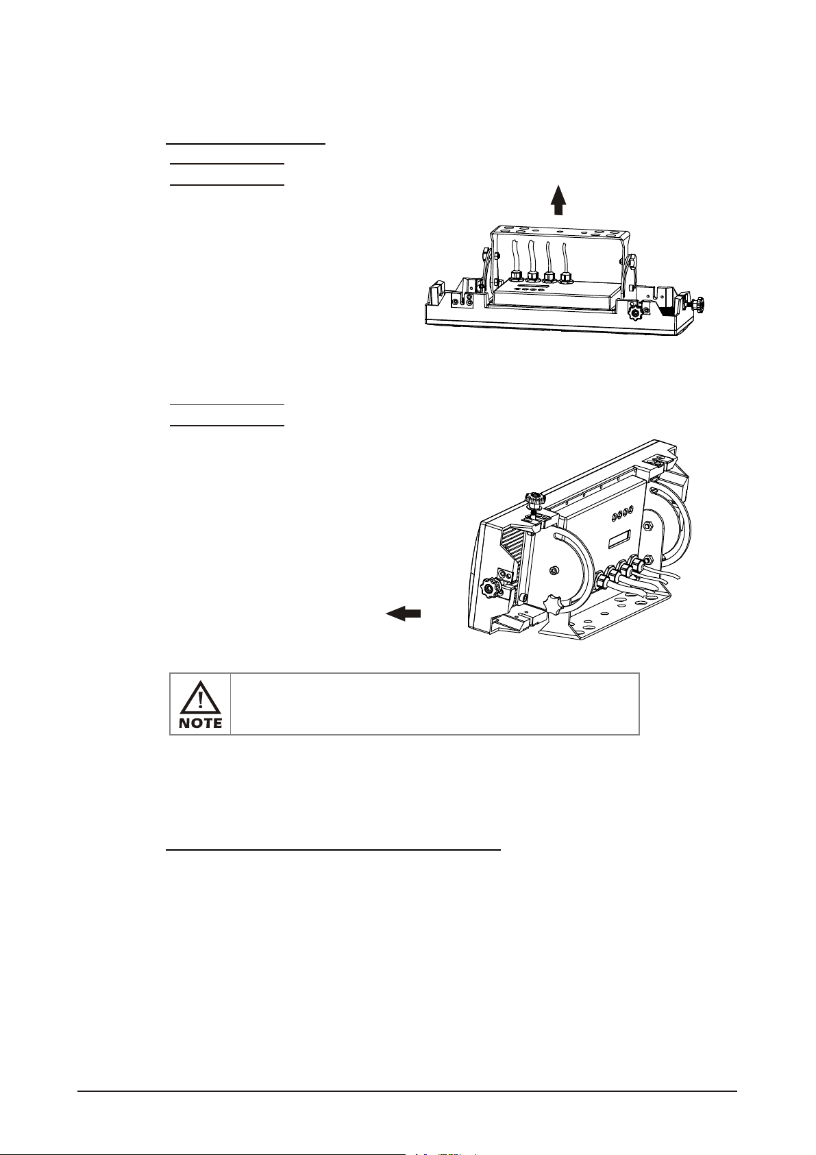
2.1 MOUNTING
HANGING
The LED MODULE can be mounted in a hanging
position using thesupport frame. Itis possible to
use any bolt of the correct size and strength to
mount the fixture. It is recommended to use at
least 2 mounting points per fixture.
Mounting with a clamp or other
mounting bracket is recommended
depending on the requirements of
your application.
UPRIGHT
The LED MODULE can be mounted upright using the support
frame. It is possible to use any bolt of the correct size and
strength to mount the fixture. It is recommended to use at
least 2 mounting points per fixture. Mounting with a
clamp or other mounting bracket is recommended
depending on the requirements of your
application.
HANGING
UPRIGHT
The LED MODULEcan be mounted at any angleand in any
position. It is possible to further adjust the angle of the LED
MODULE using thetwo adjustment knobs located on the side of
the fixture.
2.2 POWER CONNECTIONS
@ 220V:30 units may be connected in series
@120V: 15 units may be connected in series
2 INSTALLATION 7
2007.9.8
Page 10
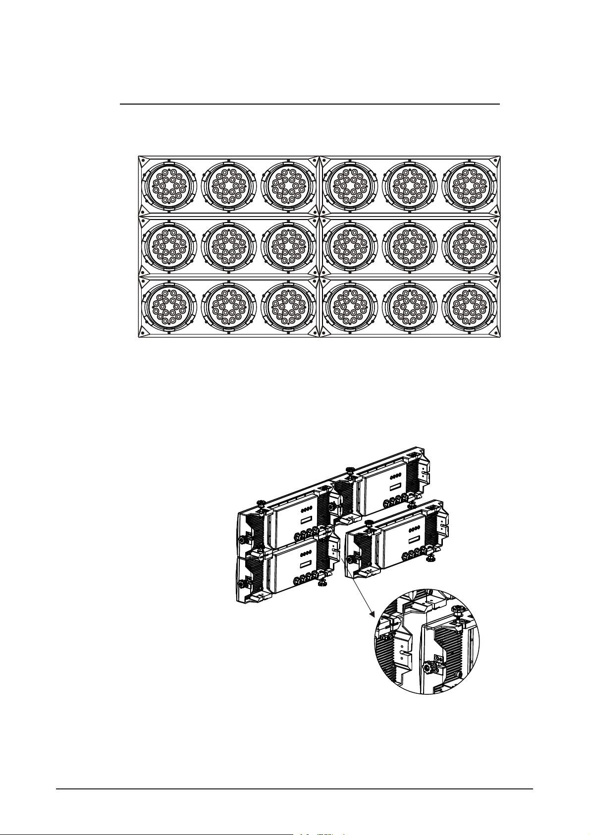
2.3 INTERLOCKING MULTIPLE FIXTURES
The diagram above shows how multiple units can be interlocked together to create a 'panel'
or 'blinder' arrangement.
The 'male' and 'female' connections enable the fixtures to be interlocked together in the
way shown in the diagram. Please note that when multiple units are mounted together it is
not necessary to attach every single unit to the truss, wall or weight supporting system.
However, it is important to ensure that all fixtures are securely locked together and that
each fixture is secured using a safety cable.
2 INSTALLATION 8
2007.9.8
Page 11
2.4 SETTING UP WITH A DMX512
CONTROLLER
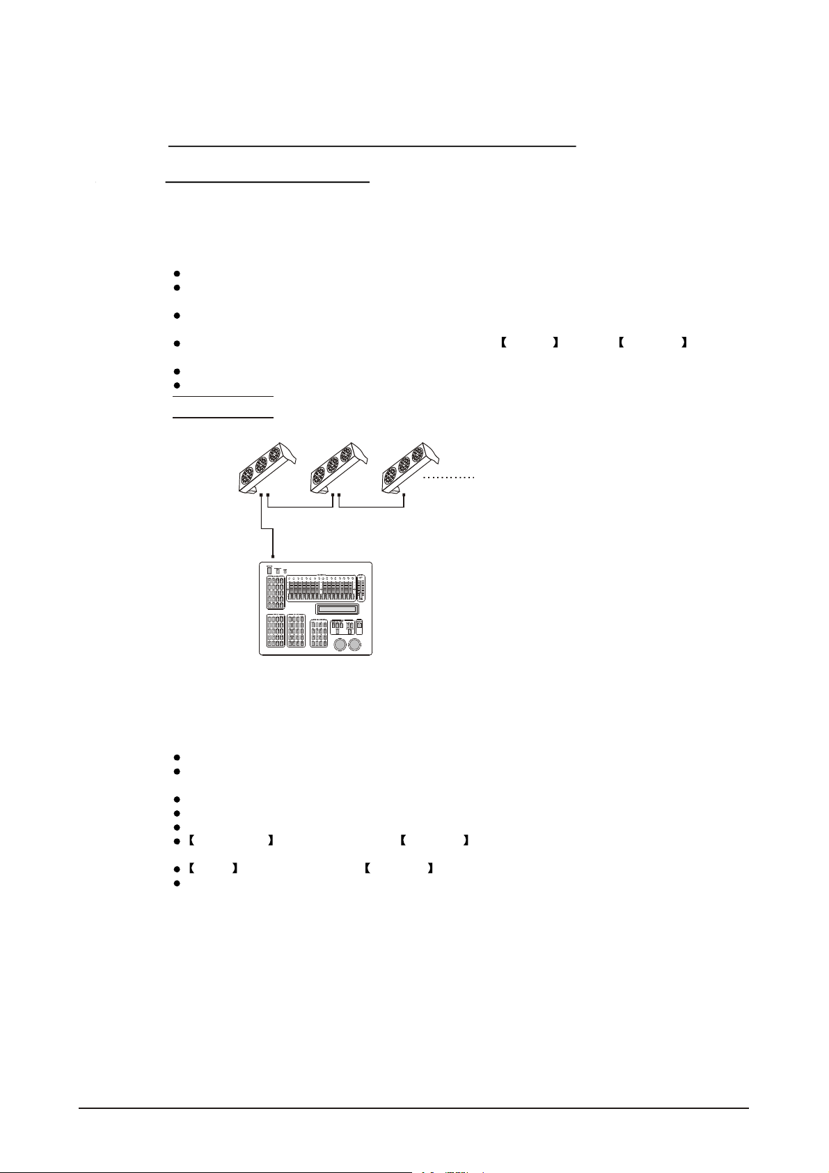
2.4-1 DMX512 ADDRESSING WITHOUT ID ADDRESSING
(STAGE 1 MODE)
Connect the DMX512controller to theunits in series.
Each unit has 12 DMX channels so theDMX Addresses should increase by increments of
12 (e.g. 1,13,25,37...)
The ID address has not been set so therefore when usingthe controller CH10 must
be inactive ( CH10=0 ).
It is also possible to deactivate ID address selecting ID OFF from the Settings menu.
on the fixture
Each DMX Address may be used as many times as required.
Any DMX address in the range from 001 to 245 may be used.
Example:
DMX Addr.1 DMX Addr.13 DMX Addr.25
DMX512
CONTROLLER
The figure above shows a simple DMX512
layout with thestarting address ofthe first
unit set at 1, with the second set at 13 and
so on... (Note that when used in this way,
the CH10 IDfunction must be inactive (CH10=0))
2.4-2 DMX512 ADDRESSING WITH ID ADDRESS(STAGE 1 MODE)
Connect the DMX512 controller to the units in series
Each unit has 12 DMX channels so the DMX Addresses should increase by increments of
12 (e.g. 1,13,25,37...)
Each DMXAddress may be used as many times as required.
Any DMX address in the range from 001 to 245 may be used.
Each DMX addressmay carry upto 66 separateID addresses.
ID Address should be set in the Settings menu on each unit in ascendingvalues
(i.e. 1,2,3...)
ID On should be set in the Settings menu on eachunit.
ID addresses are accessible from CH10 on the DMX512 controller.
2 INSTALLATION 9
2007.9.8
Page 12
Example:
DMX Addr.1
ID Addr.1
DMX512
CONTROLLER
DMX Addr.1
ID Addr.2
DMX Addr.1
ID Addr.3
DMX Addr.13
ID Addr.1
DMX Addr.13
ID Addr.2
DMX Addr.13
ID Addr.3
The figure above shows a simple DMX layout
which has usedthree units ateach DMX address.
The three unitshave different ID addresses which
allows the user to collectively control the whole
group of units at that DMX address by setting
CH10 to0, or to control each unit independently by
first selecting the DMX address and then by using
CH10 tolocate the target ID address. (Note that
when using IDaddresses it is also possible to
activate ADAS which allows for even more options
with DMX addressingand control see ADAS
Addressing section 2.2-3)
2.4-3 ADAS WITH ID ADDRESS(STAGE 1 MODE)
Connect the DMX512 controller to the units in series
Select ADAS ON from the Settings menu
ID Address should be set in the Settings menu on each unit
in ascending values (i.e. 1,2,3...)
ADAS addressing is based onthe ID addressas follows:
ADAS DMX Address = { ADAS fader * (IDAddress -1)}+ 1
ADAS addressing is activated by moving CH8 + CH10 faders to the 255 value (CH8 = 255 &
CH10 = 255)
ADAS addressing is deactivated by moving CH8 + CH10 + CH11 tothe 255 value
(CH8 = 255, CH10 = 255 & CH11 = 255)
When ADAS is deactivated, allDMX addresses willreturn to theiroriginal DMXAddress.
To permanently store ADAS DMX addresses, select ADAS copy from the Settings
menu,on the targetfixtures to store the new DMX Address.
Example:
ID Addr.1 ID Addr.2 ID Addr.3
DMX512
CONTROLLER
2 INSTALLATION 10
The figure aboveshows a simpleID address
layout using one DMX address. Each of the
units hasa different ID address which will
receive a new temporary DMX address when
ADAS is activated(unless ADAS copy
is selected). The user is able to activate and
deactivate ADASat will giving the possibility
of creating many different fixture grouping
possibilities using theID address, real DMX
address and theADAS temporaryDMX address.
2007.9.8
Page 13
Note:
When using ADAS, all fixturesmust have the
following settings from the Settings menu set correctly;
ID address Each unit should have the target ID address set
ID ON/OFF Each unit should set ID On
ADAS fader no Each unit shouldbe set tothe same numberof
ADAS ON/OFF Each unit should be set as ADAS On
in ascending order
faders as your controller(must be 12)
2.5 SETTING UP WITH THE PiX
CONTROLLER
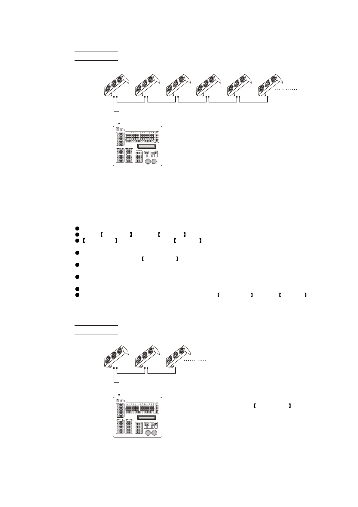
2.5-1 SINGLE ROW APPLICATION
Connect the fixturesto the PIXCONTROLLER in series.
ID Address should be set in the Settings menu on each unit in ascending values
(i.e. 1,2,3...Not required for WASH programs).
ID ON should be set in the Settings menu on each unit.
When using the PIX CONTROLLER with the fixtures there isno need toset the DMX
address.
When using the Effect programs it is important to set the Range of fixtures in the
Settings menu of the PIX CONTROLLER.
Example:
ID Addr.1 ID Addr.2 ID Addr.3 ID A ddr. 4
CONTROLLER
MOD E SE TUP UP DOW N
In the figure above the PIX controller is connected in series to 4 units with corresponding
ID addresses from1 to 4.Each fixture has ID ON in the fixture's Settings menu.
In order to activatethe Effect programs in the PIX CONTROLLER, the Range
must be set to 004 in the Settings menu of the PIXCONTROLLER.
2 INSTALLATION 11
2007.9.8
Page 14
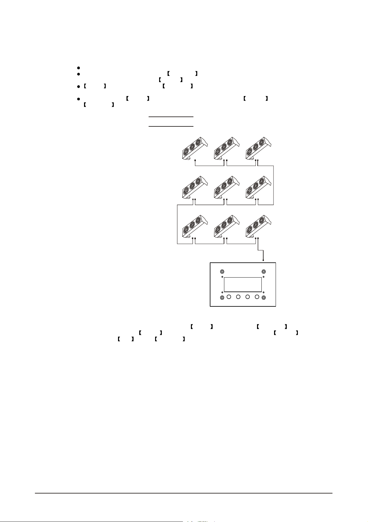
2.5-2 STANDARD BLOCK APPLICATION
Connect the fixtures to the PIX CONTROLLER in series in the directionthat is required.
ID Address should be set in the Settings menu on each unit in ascending values
(i.e. 1,2,3...Not required for WASH programs).
ID ON should be set in the Settings menu on each unit. When using the
PIX CONTROLLER with the fixtures thereis no need to setthe DMX address.
When using the Effect programs it is important to set the Range of fixtures in the
Settings menu of the PiX CONTROLLER.
Example:
ID Addr.1 ID Addr.2 ID Addr.3
ID Addr.4 ID Addr.5 ID Addr.6
ID Addr.7 ID Addr.8 ID Addr.9
CONTROLLER
MOD E SE TUP UP DO WN
In the figure above the PiX controller is connected in series to 9 units with corresponding
ID addresses from 1 to 9. Each fixture has ID ON in the fixture's Settings menu.
In order to activatethe Effect programs in the PIX CONTROLLER, the Range
must be set to 009 in the Settings menu of the PIX CONTROLLER. (Note: it is possible
to create different kinds of effects by changing the direction and position ofID Addresses)
2 INSTALLATION 12
2007.9.8
Page 15
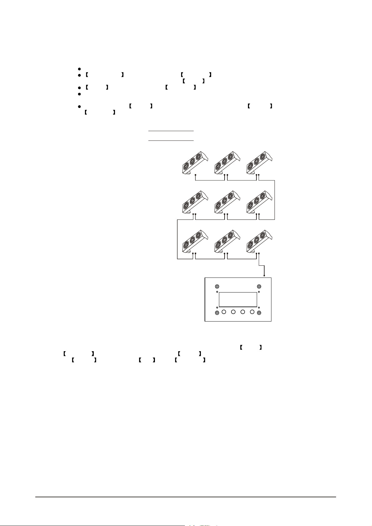
2.5-3 REPEAT ROW BLOCK APPLICATION
Connect the fixturesto the PIX CONTROLLER inseries.
ID Address should be set in the Settings menu on each unit in ascendingorder with
each row repeated (Not required for Wash programs).
ID ON should be set in the Settings menu on each unit.
When using the PRO-a CONTROLLER withthe fixtures there is noneed to setthe DMX
address.
When using the Effect programs it is important to set the Range of fixtures in the
Settings menu of the PRO-a CONTROLLER.
Example:
ID Addr.1 ID Addr.2 ID Addr.3
ID Addr.1 ID Addr.2 ID Addr.3
ID Addr.1 ID Addr.2 ID Addr.3
CONTROLLER
MOD E SE TUP UP DO WN
In the figure above the PIX controller is connected in series to 9 fixtures with each row comprising
of 3 fixtures with corresponding IDaddresses from 1 to 3. Eachrow is repeatedso that the ID
addresses appear the same was as the first row. Each fixture has ID On in the fixture's
Settings menu. In order to activate the Effect programs in the PIX CONTROLLER,
the Range must be setto 003 in the Settings menu of the PIX CONTROLLER.
2 INSTALLATION 13
2007.9.8
Page 16
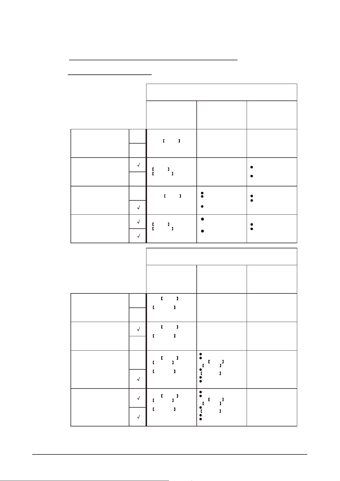
2.6 OPERATION: DMX512 Vs PiX
CONTROLLER
OPERATION WITH ADMX512 CONTROLLER
DMX512 ADDRESS
ID ADDRESS
DMX512 ADDRESS
ID ADDRESS
DMX512 ADDRESS
ID ADDRESS
DMX512 ADDRESS
ID ADDRESS
X
X
X
X
AVAILABLE
FUNCTIONS
Basic WASH
Programming
Advanced
WASH &
EFFECT
programming
Basic WASH
programming &
ADAS
Advanced
WASH &
EFFECT
programming &
ADAS
BENEFITS DRAWBACKS
No need toset
up DMXAddress
or IDAddress
Units are fully controlled
from DMX512 controller
DMX Address
ID address allows for
less DMX channels
when programming*
ADAS
User can switch be
tween ADAS& real
DMX address
Advanced fixture
mapping
OPERATION WITH THE PiX CONTROLLER
AVAILABLE
FUNCTIONS
BENEFITS DRAWBACKS
Must locate
previosly stored
DMX Address
Programming requires
many DMX channels
No auto programs
No auto programs
All ID addresses
must be set
No auto programs
All ID addressesmust
be set
Play WASH auto
X
DMX512 ADDRESS
ID ADDRESS
DMX512 ADDRESS
ID ADDRESS
DMX512 ADDRESS
ID ADDRESS
DMX512 ADDRESS
ID ADDRESS
programs, Basic
CUSTOM
programming &
X
Schedule play
Play WASH auto
programs, Basic
CUSTOM
programming &
X
Schedule play
Play WASH &
X
EFFECT auto
programs, Advanced
CUSTOM
programming &
Schedule play
Play WASH &
EFFECT auto
programs, Advanced
CUSTOM
programming &
Schedule play
2 INSTALLATION 14
No need toset up
DMX Address or
ID Address
DMX address not used
DMXAddress notused
Controlspeed and time of
all WASH &
EFFECT programs
Createpowerful
CUSTOM programs
Schedule play
Triggerauto programs with
DMXIN
DMXAddress notused
Controlspeed and time of
all WASH &
EFFECT programs
Createpowerful
CUSTOM programs
Schedule play
Triggerauto programs with
DMXIN
Only control of all
units at thesame time
Only control of all units
at the same time
All ID Addresses
must be set
All ID Addresses
must be set
2007.9.8
Page 17

3
DISPLAY PANEL OPERATION
3.1 BASIC
3.2 MENU
3.3 CREATING A STATIC COLOR
3.4 DMX512 SETTINGS
3.5 ACTIVATINGAN AUTO PROGRAM
3.6 CHANGING THE SETTINGS
3.7 A CTIVATE THE PASSWORD
3.8 POWER ON/OFF
3 DISPLAY PANEL OPERATION 15
2007.9.8
Page 18

3.1 BASIC
The LED fixtureis mounted with a LCD displayand 4 controlbuttons.
UP DOWN EXITSET
enter thecurrently selected menu or confirm the current function value
scroll 'UP' through the menulist or increase the value of the current function
scroll'DOWN' through themenu listor decrease the valueof thecurrentfunction
exit from the currentmenu orfunction
3 DISPLAY PANEL OPERATION 16
2007.9.8
Page 19

3.2 MENU
MENU
Static color
DMX512
Autoprogram
Settings
Dimmer
Red
Green
Blue
Color macros
Strobe
Address
Personality
Auto 1
Auto 2
Auto 3
Auto 4
Auto 5
Auto 6
Auto 7
Auto 8
IDaddress
ID ON/OFF
Dimmer
Red
Green
Blue
Colormacros
Strobe
Address 1 512
STAGE 1
STAGE 2
ARC 1
ID address
001 066
ID
ON/OFF
0 255
0 255
0 255
0 255
0 255
0 255
MENU
Password
RAS ON/OFF
ADASON/OFF
ADASfaderno
CopyON/OFF
Reset to
Factory settings
PasswordON/OFF
Setpassword
RAS
ON/OFF
ADAS
ON/OFF
ADASfaderno
01 244
Copy
ON/OFF
Resetconfirm
Password
ON/OFF
SetPassword
3 DISPLAY PANEL OPERATION
17
2007.9.8
Page 20

3.3 CREATING A STATIC COLOR
MENU
Static color
Static colour
Combine RED, GREEN and BLUE to create an infinite range of colors(0-255)
Enter Color macros allow to choose 18color macros
Set value of dimmer (0-255)
Set the valueof the strobe (0-20Hz)
3.4 DMX512 SETTINGS
Dimmer
Red
Green
Blue
Color macros
Strobe
Dimmer
Red
Green
Blue
Colormacros
Strobe
0 255
0 255
0 255
0 255
0 255
0 255
MENU
DMX512
Address
Personality
Address 1 512
STAGE 1
STAGE 2
ARC 1
DMX512 address
Enter the DMX address mode to set the DMX address
Activate control from outside sourceby activating ON
Enter Personality mode to choose DMX mode: STAGE 1 , STAGE 2 or
ARC 1
3 DISPLAY PANEL OPERATION
18
2007.9.8
Page 21

3.5 ACTIVATING ANAUTO PROGRAM
MENU
Autoprogram
Auto 1
Auto 2
Auto 3
Auto 4
Auto 5
Auto 6
Auto 7
Auto 8
Auto Program
Select the target Auto mode and press Set to display
3.6 CHANGING THE SETTINGS
MENU
Settings
IDaddress
ID ON/OFF
ID address
001 066
ID
ON/OFF
RAS ON/OFF
ADASON/OFF
ADASfaderno
CopyON/OFF
Reset to
Factory settings
RAS
ON/OFF
ADAS
ON/OFF
ADASfaderno
01 244
Copy
ON/OFF
Resetconfirm
Settings
Enter the ID Address to set the ID address for the unit
Enter ID ON/OFF in order to allow/disallow ID address function from the
DMX512 controller
RAS ON/OFF reserve for future use.
In ADAS ON/OFF select allow/disallow Automatic DMX512 Addressing
System (ADAS)
Enter the ADAS fader no to set the numberof channel faders in each layer
of the controller
In the Copy ON/OFF menu select whetherto allow copy of DMX andID address
to unit.
Enter the Reset to Factory Settings in order to reset to default factory settings.
3 DISPLAY PANEL OPERATION 19
2007.9.8
Page 22

3.7 A CTIVATE THE PASSWORD
MENU
Password
Enter the Password mode to set passwordYES/NO
When password is activated, displaywill demand password each time
the fixture is powered on.
Enter the Set password menu to change password.
Set new password using the UP & DOWN keys.
Input an 8 digit password and then press SET to confirm
NOTE: In the event thatthe password is forgotten. Please use the factory password shown below.
UP > DOWN > UP > DOWN > UP > UP > DOWN > DOWN
3.8 POWER ON/OFF
TURN OFF When display shows MENU , hold down the EXIT key
for 3 seconds to turn off power.
TURN ON When display isoff, hold down the EXIT key for 3 seconds toturn on power.
ON/OFF
SetPassword
Password
ON/OFF
Password
3 DISPLAY PANEL OPERATION 20
2007.9.8
Page 23

4
USING A DMX512
CONTROLLER
4.1 BASIC ADDRESSING
4.2 CHANNELASSIGNMENT
4.3 BASIC INSTRUCTIONS FOR DMX512
OPERATION
4.4 PROGRAMMING WITH ADMX512
CONTROLLER: EXAMPLES
4 USING ADMX512 CONTROLLER 21
2007.9.8
Page 24

4.1 BASIC ADDRESSING
Connect all of the unitsin series using standard DMX512signal cable or the IP65rated cable
provided.
Set the DMX512 address in the 'DMX512 Address' menu.
It is possible to have the same DMX address or independent addresses for each fixture.
4.2 CHANNELASSIGNMENT
Note:
This product has three DMX512 channel configurations (STAGE 1 , STAGE 2 & ARC 1).
Both STAGE 1 and STAGE 2 have two DMX modse: DMX MODE 1 and
DMX MODE 2
Ch9 is used to switch from one DMX MODE 1 (0-244) to DMXMODE 2 (245-255).
ARC 1
CHANNEL VALUE
1
2
3
0 4
0 4
0 4
5 255
FUNCTION
RED
No function
0-100%5 255
GREEN
No function
0-100%5 255
BLUE
No function
0-100%
4 USING ADMX512 CONTROLLER
22
2007.9.8
Page 25

STAGE 1(DM X MODE 1)
CHANNEL VALUE
1
2
3
4
5
6
7
8
9
0 4
0 4
0 4
0 4
0 4
0 4
5 255
0 4
0 4
0 4
5 34 Color-Cycle Mode 1
35 64 Color-Cycle Mode 2
65 94 Color-Cycle Mode 3
95 124 Color-CycleMode4 (speedcanbe adjustedusingChannel 11)
125 154 Color-Cycle Mode 5
155 184 Color-Cycle Mode 6
185 214 Color-Cycle Mode 7
215 244 Color-Cycle Mode 8
245 255 DMX MODE 2
FUNCTION
RED
No function
0-100%5 255
GREEN
No function
0-100%5 255
BLUE
No function
0-100%5 255
YELLOW
No function
0-100%5 255
CYAN
No function
0-100%5 255
PURPLE
No function
0-100%
WHITE
No function
0-100%5 255
STROBE
No function
Strobe (slow to fast)5 255
MODE SELECTION
No function
4 USING ADMX512 CONTROLLER
23
2007.9.8
Page 26

CHANNEL VALUE FUNCTION
ID ADDRESS SELECTION (also seepg. 26)
0 9 Select all ID addresses
10 19
20
30
.
.
.
.
.
10
11
12
.
200
210
211
212
.
.
.
.
.
.
215
0 4 #1 ON #2 ON #3 ON
5 34 #1 ON
35 64 #2 ON
65 94 #3 ON
95 124 #1 ON #2 ON
125 154 #2 ON #3 ON
155 184 #1 ON #3 ON
185 214 #1 ON #2 ON #3 ON
215 255
0 255
0
5
10
.
.
.
.
.
.
ID address #1
29
ID address #2
39
ID address #3
209
ID address #20
ID address #21
ID address #22
ID address #23
ID address #66
MODULE SELECTION
#1 OFF #2 OFF #3 OFF
Speed control ofCH9 Color-Cycle Mode 4
EFFECT MACRO
4
No function
9
Effect MACRO #1
14
Effect MACRO #2
.
.
.
.
.
.
250
255
4 USING ADMX512 CONTROLLER 24
Effect MACRO #50
2007.9.8
Page 27

STAGE 1(DM X MODE 2)
CHANNEL VALUE FUNCTION
0 4 No function
5 34 RED
35 64 GREEN
1
2
3
4
5
6
7
8
9
65 94
95 124 YELLOW
125 154 CYAN
155 184 PURPLE
185 255 PINK-WHITE
0 4 No function
5 34 RED
35 64
65 94 BLUE
95 124 YELLOW
125 154 CYAN
155 184 PURPLE
185 214
0 4 No function
5 34 RED
35 64 GREEN
65 94 BLUE
95 124 YELLOW
125 154 CYAN
155 184 PURPLE
185 214 PINK-WHITE
0 4
5 255
0 244
245 255
MODULE #1
BLUE
MODULE #2
GREEN
PINK-WHITE
MODULE #3
NO FUNCTION
NO FUNCTION
NO FUNCTION
NO FUNCTION
STROBE
No function
Strobe (slow to fast)
MODE SELECTION
DMX MODE 1
DMX MODE 2
4 USING ADMX512 CONTROLLER
25
2007.9.8
Page 28

CHANNEL VALUE FUNCTION
ID ADDRESS SELECTION (also seepg. 26)
0 9 Select all ID addresses
29
39
209
ID address #1
ID address #2
ID address #3
ID address #20
ID address #21
ID address #22
ID address #23
ID address #66
NO FUNCTION
NO FUNCTION
10
11
12
10 19
20
30
200
210
211
212
215
.
.
.
.
.
.
.
.
.
.
.
.
4 USING ADMX512 CONTROLLER 26
2007.9.8
Page 29

STAGE 2(DM X MODE 1)
CHANNEL VALUE
1
2
3
4
5
6
0 4
0 4
0 4
0 4
0 9
10 29
30
39
40
49
50
69
70
79
80
89
90
109
110
119
120
129
130
149
150 159
160 169
170
189
190
199
200
219
220
229
230
249
250
255
0 4
FUNCTION
DIMMER
No function
0-100%5 255
RED
No function
0-100%5 255
GREEN
No function
0-100%5 255
BLUE
No function
0-100%5 255
COLOR MACROS
No function
RED (100%)
RED+GREEN (R85%+G15%)
RED+GREEN (R60%+G40%)
YELLOW (100%)
RED+GREEN (R15%+G85%)
RED+GREEN (R40%+G60%)
GREEN (100%)
GREEN+BLUE (G85%+B15%)
GREEN+BLUE (G60%+B40%)
BLUE (100%)
BLUE+GREEN (G85%+B15%)
BLUE+GREEN (G60%+B40%)
CYAN (100%)
GREEN+PURPLE (G50%+P50%)
PURPLE (100%)
PURPLE+GREEN (P80%+G20%)
RGB (100%)
WHITE (100%)
STROBE
No function
Strobe (slow to fast)5 255
4 USING ADMX512 CONTROLLER 27
2007.9.8
Page 30

CHANNEL VALUE FUNCTION
MODE SELECTION
0 4 No function
5 34 Color-Cycle Mode 1
35 64 Color-Cycle Mode 2
65 94 Color-Cycle Mode 3
7
8
9
10
95 124 Color-CycleMode4 (speedcanbe adjustedusingChannel 11)
125 154
155 184 Color-Cycle Mode 6
185 214 Color-Cycle Mode 7
215 244 Color-Cycle Mode 8
245 255 DMX MODE 2
0 9 Select all ID addresses
10 19
20
30
.
.
.
.
.
.
200
210
211
212
.
.
.
.
.
.
215
0 4 #1 ON #2 ON #3 ON
5 34
35 64 #2 ON
65 94 #3 ON
95 124 #1 ON #2 ON
125 154 #2 ON #3 ON
155 184 #1 ON #3 ON
185 214 #1 ON #2 ON #3 ON
215 255 #1 OFF #2 OFF #3 OFF
0 255
0
5
10
.
.
.
.
.
.
Color-Cycle Mode 5
ID ADDRESS SELECTION (also seepg. 26)
ID address #1
29
ID address #2
39
ID address #3
209
ID address #20
ID address #21
ID address #22
ID address #23
ID address #66
MODULE SELECTION
#1 ON
Speed control ofCh7 Color-Cycle Mode 4
EFFECT MACRO
4
No function
9
Effect MACRO #1
14
Effect MACRO #2
.
.
.
.
.
.
250
255
4 USING ADMX512 CONTROLLER 28
Effect MACRO #50
2007.9.8
Page 31

STAGE 2(DM X MODE 2)
CHANNEL VALUE FUNCTION
0 4 No function
5 34 RED
35 64 GREEN
1
2
3
4
5
6
7
65 94
95 124 YELLOW
125 154 CYAN
155 184 PURPLE
185 255 PINK-WHITE
0 4 No function
5 34 RED
35 64
65 94 BLUE
95 124 YELLOW
125 154 CYAN
155 184 PURPLE
185 214
0 4 No function
5 34 RED
35 64 GREEN
65 94 BLUE
95 124 YELLOW
125 154 CYAN
155 184 PURPLE
185 214 PINK-WHITE
0 4
5 255
0 244
245 255
MODULE #1
BLUE
MODULE #2
GREEN
PINK-WHITE
MODULE #3
NO FUNCTION
NO FUNCTION
STROBE
No function
Strobe (slow to fast)
MODE SELECTION
DMX MODE 1
DMX MODE 2
4 USING ADMX512 CONTROLLER
29
2007.9.8
Page 32

CHANNEL VALUE FUNCTION
ID ADDRESS SELECTION (also seepg. 26)
0 9 Select all ID addresses
29
39
209
ID address #1
ID address #2
ID address #3
ID address #20
ID address #21
ID address #22
ID address #23
ID address #66
NO FUNCTION
NO FUNCTION
10
10 19
20
30
.
.
.
.
.
.
8
200
210
211
212
.
.
.
.
.
.
215
9
4 USING ADMX512 CONTROLLER 30
2007.9.8
Page 33

DMX value ID address
0 9
10 19
20 29
30 39
40 49
50 59
60 69
70 79
80 89
90 99
100 109
110 11 9
120 129
130 139
140 149
150 159
160 169
170 179
180 189
190 199
200 209
210
211
212
213
214
215
216
217
218
219
220
221
222
ID1 66
ID1
ID2
ID3
ID4
ID5
ID6
ID7
ID8
ID9
ID10
ID11
ID12
ID13
ID14
ID15
ID16
ID17
ID18
ID19
ID20
ID21
ID22
ID23
ID24
ID25
ID26
ID27
ID28
ID29
ID30
ID31
ID32
ID33
DMX value ID address
223
224
225
226
227
228
229
230
231
232
233
234
235
236
237
238
239
240
241
242
243
244
245
246
247
248
249
250
251
252
253
254
255
ID34
ID35
ID36
ID37
ID38
ID39
ID40
ID41
ID42
ID43
ID44
ID45
ID46
ID47
ID48
ID49
ID50
ID51
ID52
ID53
ID54
ID55
ID56
ID57
ID58
ID59
ID60
ID61
ID62
ID63
ID64
ID65
ID66
4 USING ADMX512 CONTROLLER 31
2007.9.8
Page 34

4.3 BASIC INSTRUCTIONS FOR DMX512
OPERATION
STAGE 1 DMX MODE 1
RED, GREEN & BLUE COLOR SELECTION
CH1, CH2 &CH3 control theintensity ratio ofeach of theRED, GREEN & BLUE LEDs.
When the slider isat the highest position (255) the intensity of the color is the
maximum.
CH1, CH2 &CH3 can becombined together tocreate over 16 million colors.
CH1, CH2, CH3 have priority over CH4, CH5, CH6 & CH7
YELLOW, CYAN, PURPLE & WHITE
CH4, CH5, CH6 &CH7 are independent colors and cannotbe mixed with anyother
color control channel.
When multiple channelsare used atthe same time;lower channel number ispriority
(i.e. CH4 has priority over all channels 1-6)
STROBE
CH8 is the strobechannel and controls the strobe effects of CH1, CH2, CH3, Ch4,
CH5, CH6, & CH7
The strobe is with anadjustable speed with a maximum of20Hz.
The strobe is not active with CH9 &CH12
MODE SELECTION
CH9 allows the user to activate DMX MODE 1 (0-244) or DMX MODE 2 (245-255).
CH9 values 5-244 can only be activated when CH1 to CH7 are not
activated
When Color-Cycle Mode 4 is selected CH11controls the speed of the Color-cycle.
ID ADDRESSSELECTION
CH10 is usedto select thetarget ID address.
Each independent DMX address may haveupto 66 independentID addresses.
An IDaddress of 0 will be activatedby all IDaddress locations.
MODULE SELECTION
CH11controls set combinations of the threeLED MODULES present in each unit.
CH11has priority over CH12 when first activated
EFFECT MACRO
The effect MACRO channel allows theuser to select from combinations of different
colors andLED modules in a quick-and-easy action.
CH12 has priority over color control channels (CH1, CH2, CH3, CH4, CH5,CH6 &
CH7)
CH12 has priority over CH11 when first activated
CH12 has priority over Ch9 & Ch11
4 USING ADMX512 CONTROLLER 32
2007.9.8
Page 35

STAGE 1 DMX MODE 2
MODULE #1, MODULE #2 & MODULE #3 SELECTION
CH1, CH2 &CH3 allow quick-and-simple control of thethree LED MODULEs
Control of the LED MODULEs can be used in conjunction with all other channels in
DMX MODE 2
STROBE
CH8 is the strobechannel and controls the strobe effects of CH1, CH2 & Ch3
The strobe is with anadjustable speed with a maximum of20Hz.
MODE SELECTION
CH9 allows the user to activate DMX MODE 1 (0-244) or DMX MODE 2 (245-255).
ID ADDRESSSELECTION
CH10 is usedto select thetarget ID address.
Each independent DMX address may haveup to 66independent ID addresses.
4 USING ADMX512 CONTROLLER 33
2007.9.8
Page 36

STAGE 2 DMX MODE 1
DIMMER
CH1 control the dimmer intensity ofCh2, Ch3, Ch4, Ch5, Ch6 & Ch9.
When Ch1is set to 0 ,Ch2, Ch3, Ch4, Ch5, Ch6 & Ch9 no funtion..
When the slideris at the highest position(255) the dimmer intensity is the maximum.
CH1 has priority over Ch7 when first activated.
RED, GREEN & BLUE COLOR SELECTION
CH2 , Ch3 & CH4 control the intensity ratio of each of the RED, GREEN & BLUE
LEDs.
When the slider isat the highest position (255) the intensity of the color is the
maximum.
CH2 , Ch3& CH4 canbe combined togetherto create over16 million colors.
COLOR MACRO
The COLOR MACRO channel allowsthe user to select from different color macro .
Ch5 has priority over Ch2, Ch3& Ch4.
STROBE
CH6 is the strobechannel and controls the strobe effects of CH2, CH3, Ch4, CH5 &
CH9
The strobe is with anadjustable speed with a maximum of20Hz.
The strobe is not active with CH7 &CH10
MODE SELECTION
CH7 allows theuser to activate DMX MODE 1 (0-244) or DMX MODE 2 (245-255).
Ch7 has priority over Ch1 when first activated.
Ch7 has priority over Ch10 when first activated.
When Color-Cycle Mode 4 is selected Ch9 controls the speed of the Color-cycle.
ID ADDRESSSELECTION
CH8 is usedto select thetarget ID address.
Each independent DMX address may haveupto 66 independentID addresses.
An IDaddress of 0 will be activatedby all IDaddress locations.
MODULE SELECTION
Ch9 controls setcombinations of the three LED MODULESpresent in eachunit.
EFFECT MACRO
The effect MACRO channel allows the user to select from combinations of different
colors andLED modules in a quick-and-easy action.
CH10 has priority over CH1.
CH10 has priority over Ch7 when first activated
4 USING ADMX512 CONTROLLER 34
2007.9.8
Page 37

STAGE 2 DMX MODE 2
MODULE #1, MODULE #2 & MODULE #3 SELECTION
CH1, CH2 &CH3 allow quick-and-simple control of thethree LED MODULEs
Control of the LED MODULEs can be used in conjunction with all other channels in
DMX MODE 2
STROBE
CH6 is the strobechannel and controls the strobe effects of CH1, CH2 & Ch3
The strobe is with anadjustable speed with a maximum of20Hz.
MODE SELECTION
CH7 allows the user to activate DMX MODE 1 (0-244) or DMX MODE 2 (245-255).
ID ADDRESSSELECTION
CH8 is usedto select thetarget ID address.
Each independent DMX address may haveup to 66independent ID addresses.
ARC 1 MODE
RED, GREEN & BLUE COLOR SELECTION
CH1 , Ch2 & CH3 controlthe intensity ratio of each of the RED, GREEN & BLUE
LEDs.
When the slider isat the highest position (255) the intensity of the color is the
maximum.
CH1 , Ch2& Ch3 canbe combined togetherto create over16 million colors.
4 USING ADMX512 CONTROLLER 35
2007.9.8
Page 38

4.4 PROGRAMMING WITH A DMX512
CONTROLLER: EXAMPLES(STAGE 1)
EXAMP LE 1
Before any operationis performed onthe DMX512 controller, confirm that all DMX
channels are set to zero.
NOTE
When programming astep / scene that involves operating CH10 toselect an IDaddress,
this channels operationshould be performed first
Step 1
Step 2
Step 3
Step 4
Step 5
Step 6
CH1
CH2
CH3
CH9
CH10
CH1
CH2
CH3
CH9
CH10
CH1
CH2
CH3
CH9
CH10
CH1
CH2
CH3
CH9
CH10
CH1
CH2
CH3
CH9
CH10
CH1
CH2
CH3
CH9
CH10
to select RED for MODULE #1(ID Add. 1)
20
to select OFF for MODULE #2(ID Add. 1)
0
to select OFF for MODULE #3(ID Add. 1)
0
to select DMX mode 2
255
to select IDAdd. 1
11
to select OFF for MODULE #1
0
to select RED for MODULE #2(ID Add. 1)
20
to select OFF for MODULE #3(ID Add. 1)
0
to select DMX mode 2
255
to select IDAdd: 1
11
to select OFF for MODULE #1(ID Add. 1)
0
to select OFF for MODULE #2
0
to select RED for MODULE #3(ID Add. 1)
20
to select DMX mode 2
255
to select IDAdd: 1
11
to select GREEN for MODULE #1
50
(ID Add. 1 & ID Add. 2)
to select OFF for MODULE #2
0
(ID Add. 1 & ID Add. 2)
to select OFF for MODULE #3
0
255
to select DMX mode 2
to select all ID Addresses
0
to select OFF for MODULE #1
0
(ID Add. 1 & ID Add. 2)
to select GREEN for MODULE #2
50
(ID Add. 1 & ID Add. 2)
to select OFF for MODULE #3
0
(ID Add. 1 & ID Add. 2)
to select DMX mode 2
255
to select all ID Addresses
0
to select OFF for MODULE #1
0
(ID Add. 1 & ID Add. 2)
to select OFF for MODULE #2
0
(ID Add. 1 & ID Add. 2)
to select GREEN for MODULE #3
50
(ID Add. 1 & ID Add.2)
to select DMX mode 2
255
to select all ID Addresses
0
ID Addr.2ID Addr.1
ID Addr.2ID Addr.1
ID Addr.2ID Addr.1
ID Addr.1 ID Addr.2
ID Addr.1 ID Addr.2
ID Addr.1 ID Addr.2
Red Green Blue
4 USING ADMX512 CONTROLLER 36
2007.9.8
Page 39

EXAMP LE 2
Before any operation is performed on the DMX512 controller, confirm that all DMX
channels are set to zero.
Step 1
Step 2
Step 3
Step 4
Step 5
CH1
CH2
CH3
CH9
CH10
CH1
CH2
CH3
CH9
CH10
CH1
CH2
CH3
CH9
CH20
CH1
CH2
CH3
CH9
CH10
CH1
CH2
CH3
CH9
CH10
to select RED for all MODULES(ID Add. 1)
255
to select NOGREEN for allMODULES
0
(ID Add.1)
to select NOBLUE for all MODULES
0
(ID Add.1)
to select DMX mode 1
0
to select IDAdd. 1
11
to select OFF for all MODULES(ID Add. 1)
0
to select NOGREEN for allMODULES
0
(ID Add.1)
to select NOBLUE for all MODULES
0
(ID Add.1)
to select DMX mode 1
0
to select IDAdd: 1
11
to select NORED for allMODULES
0
(ID Add.2)
to select NOGREEN for allMODULES
0
(ID Add.2)
to select BLUE for all MODULES (ID Add. 2)
255
to select DMX mode 1
0
to select IDAdd: 2
12
to select NOGREEN for allMODULES
0
(ID Add.1& ID Add.2)
to select GREEN for all MODULES
50
(ID Add.1& ID Add.2)
to select NOGREEN for allMODULES
0
(ID Add.1& ID Add. 2)
to select DMX mode 2
0
to select all ID Addresses
20
to select OFF for MODULE #1(ID Add. 2)
0
to select GREEN for MODULE #2(ID Add. 2)
0
to select OFF for MODULE #3(ID Add.1)
0
to select DMX mode 2
0
to select IDAdd: 2
0
ID Addr.2ID Addr.1
ID Addr.1 ID A ddr.2
ID Addr.1 ID A ddr.2
ID Addr.2ID Addr.1
ID Addr.1 ID A ddr.2
CH1
20
to select RED for MODULE #1(ID Add. 2)
to select GREEN for MODULE#2 (ID Add.2)
50
CH2
Step 6
CH3
CH9
CH10
to select BLUEfor MODULE #3(ID Add.2)
80
to select DMX mode 2
0
to select IDAdd: 2
12
4 USING ADMX512 CONTROLLER 37
ID Addr.1 ID A ddr.2
Red Green Blue
2007.9.8
Page 40

Step 7
Step 8
CH1
CH2
CH3
CH9
CH10
CH1
CH2
CH3
CH9
CH10
to set OFFfor MODULE #1(ID Add. 1)
0
to select OFF for MODULE 2 (ID Add.1)
0
to select OFF for MODULE 3 (ID Add.1)
0
to select DMX mode 1
0
to select IDAdd. 1
11
255
to select RED for all MODULES(ID Add. 2)
to select NOGREEN for allMODULES
0
(ID Add.2)
to select NOBLUE for all MODULES
0
(ID Add.2)
0
to select DMX MODE 1
to select IDAdd: 2
12
ID Addr.2ID Addr.1
ID Addr.2ID Addr.1
4 USING ADMX512 CONTROLLER 38
Red Green Blue
2007.9.8
Page 41

EXAMP LE 3
Before any operation is performed on the DMX512 controller, confirm that all DMX
channels are set to zero.
Step 1
Step 2
Step 3
Step 4
Step 5
CH1
CH2
CH3
CH9
CH10
CH1
CH2
CH3
CH9
CH10
CH1
CH2
CH3
CH9
CH10
CH1
CH2
CH3
CH9
CH10
CH1
CH2
CH3
CH9
CH10
to select RED for all MODULES(ID Add. 1)
255
toselectNOGREEN forallMODULES(ID Add.1)
0
toselect NO BLUE forallMODULES(ID Add.1)
0
to select DMX mode 1
0
to select IDAdd. 1
11
toselect NO REDforall MODULES (ID Add.2)
0
toselect GREENfor allMODULES(ID Add.2)
255
0
toselect NO BLUE forallMODULES(ID Add.2)
to select DMX mode 1
0
to select IDAdd: 2
12
toselect NO REDforall MODULES (ID Add.3)
0
toselectNO GREENforall MODULES(IDAdd.3)
0
toselectBLUEforallMODULES (IDAdd.3)
255
to select DMX mode 1
0
to select IDAdd: 3
13
toselectNO REDforall MODULES(IDAdd.1)
0
toselectNO GREENforall MODULES(IDAdd.1)
0
0
toselectNO BLUEforall MODULES(IDAdd.1)
to select DMX mode 1
0
to select IDAdd. 1
11
toselectNO REDforall MODULES(IDAdd.2)
0
toselectNO GREENforall MODULES(IDAdd.2)
0
0
toselectNO BLUEforall MODULES(IDAdd.2)
to select DMX mode 1
0
to select IDAdd: 2
12
4 USING ADMX512 CONTROLLER 39
Red Green Blue
2007.9.8
Page 42

5
USING THE CONTROLLER
5.1 BASIC
5.2 SETTING UP
5.3 MENU
5.4 WASH PROGRAM
5.5 EFFECTPROGRAM
5.6 CUSTOM PROGRAM
5.7 PLAY SCHEDULE
5.8 CLOCK
5.9 SCHEDULE
5.10 SETTINGS
5.11 ACTIVATE THE PASSWORD
5.12 PiX CONTROLLER EXTERNAL
CONTROL VIA DMX512
5 USING THE CONTROLLER 40
2007.9.8
Page 43

5.1 BASIC
The CONTROLLER ismounted with aLCD display and 4 control buttons.
MODE SETUP UP DOWN
UP
Scroll through the main menu or exit from the current sub-menu
Scroll 'UP' through the menu list or increase the value of the current function
Scroll 'DOWN' through the menu list or decrease the value of thecurrent function
MOD E
SETUP enter the currently selected menu or confirm thecurrent function value
DOWN
5.2 SETTING UP
Connect the controller to the LED MODULES using the signal cable provided. (see diagram
below)
CONTROLLER
MOD E SE TUP UP DO WN
Power on all the LEDMODULES and then power on the PiX Controller in orderto
auto-detect DMX addresses (Alternatively select [Detect device] from the [Settings] menu)
Set ID addresses on theLED MODULES in ascending order(i.e. 1,2,3...)
Set the [Range] in the[Settings] menu
Note that for [Wash] programs the ID address and the [Range] do notneed to be set
5 USING THE CONTROLLER 41
2007.9.8
Page 44

5.3 MENU
MENU
Wash program Wash 1
Wash 2
Wash 8
Effectprogram Effect 1
Effect 2
Effect 8
Custom program
Custom 1
Custom 1
Edit
Scene 1
Scene 2
Scene 100
Wash 1
Edit
Wash 2
Edit
Wash 8
Edit
Effect 1
Edit
Effect 2
Edit
Effect 8
Edit
Scene 1
IDaddress
Scene 1
Steptime
Scene 1
Fadetime
Scene 1
Red
Scene 1
Green
Scene 1
Blue
Scene 1
Module
Scene 1
Strobe
Step time 001
Fadetime 001
Step time 001
Fadetime 001
Step time 001
Fadetime 001
Speed 001
Speed 001
Speed 001
Scene 1
IDaddress
Scene 1
Module 001
Scene 1
Red 001
Scene 1
Green 001
Scene 1
Blue 001
Scene 1
Strobe 001
Scene 1
Steptime 001
Scene 1
Fadetime 001
Playschedule
Clock Time now
5 USING THE CONTROLLER 42
Schedule
>>>
Edittime
02/08/2006
13:50:24
02/08/2006
13:50:24
2007.9.8
Page 45

Schedule
Wash 1
00:00>>>00:00
Wash 2
00:00>>>00:00
Start >>>End
00:00>>>00:00
Start >>>End
00:00>>>00:00
Wash 8
00:00>>>00:00
Effect 1
00:00>>>00:00
Effect 2
00:00>>>00:00
Effect 8
00:00>>>00:00
Custom 1
00:00>>>00:00
Custom 2
00:00>>>00:00
Custom 8
00:00>>>00:00
Settings DMXaddress
Range
Allow edit
Detectdevice
Start >>>End
00:00>>>00:00
Start >>>End
00:00>>>00:00
Start >>>End
00:00>>>00:00
Start >>>End
00:00>>>00:00
Start >>>End
00:00>>>00:00
Start >>>End
00:00>>>00:00
Start >>>End
00:00>>>00:00
DMXaddress
001
Range
001
Allow edit
YES NO
>>>
Reset to
Factorysettings
Password PasswordON/OFF
Setpassword
Reset
YES NO
Password
ON/OFF
SetPassword
5 USING THE CONTROLLER 43
2007.9.8
Page 46

5.4 WASH PROGRAM
MENU
Wash program Wash 1
Wash
Select from the eight Wash programs andinstantly play
When Edit is allowed in [Settings] it is possible to set the Step time
and Fade time
The unit of Step time is 5 seconds and can be adjusted from 1 to 255
The unit of Fade time is 1 seconds and can be adjusted from 1 to 255
5.5 EFFECT PROGRAM
MENU
Effectprogram Effect 1
Wash 2
Wash 8
Effect 2
Wash 1
Edit
Wash 2
Edit
Wash 8
Edit
Effect 1
Edit
Effect 2
Edit
Step time 001
Fadetime 001
Step time 001
Fadetime 001
Step time 001
Fadetime 001
Speed 001
Speed 001
Effect 8
Effect 8
Edit
Speed 001
Effect
Select from the eight Effect programs and instantly play
When Edit is allowed in Settings it is possible to set the Speed
The Speed of the Effect can be adjusted from 1 to 255
5 USING THE CONTROLLER 44
2007.9.8
Page 47

5.6 CUSTOM PROGRAM
MENU
Custom program
Custom 1
Custom 1
Edit
Scene 1
Scene 2
Scene 100
Scene 1
IDaddress
Scene 1
Step time
Scene 1
Fadetime
Scene 1
Red
Scene 1
Green
Scene 1
Blue
Scene 1
Module
Scene 1
Strobe
Scene 1
ID address
Scene 1
Module 001
Scene 1
Red 001
Scene 1
Green 001
Scene 1
Blue 001
Scene 1
Strobe 001
Scene 1
Step time 001
Scene 1
Fade time 001
Custom
Select from the eight Custom programs and instantly play
When Edit is allowed in Settings it is possible to enter the edit section
Scene
Select from 100 scenesto create or edit
Scenes that are not required should have the Step time set as 0
ID address
Select the ID address of the target unit
Set the ID address as 0to include all ID addresses
ID address action from previous steps is stored until changed allowing for
combination colors/effects using different ID addresses
Module
Select the [Module] to be active:
0=#1 #2 # 3
1=#1
2=#2
3=#3
4=#1 #2
5=#2 #3
6=#1 #3
Red , Green & Blue
Combine RED, GREEN & Blue to create an infinite range of colors (0-255)
Strobe
Select the strobe speed from 0-20Hz
Step time
Select the Step time of the current scene
The unit of Step time is 0.1s for the range 0-10 and 1 sec for the range 11-255
Fade time
Select the [Fade time] of thecurrent scene
The unit of [Fade time] is 1 second and can be adjusted from 0 to 255
5 USING THE CONTROLLER 45
2007.9.8
Page 48

5.7 PLAY SCHEDULE
MENU
Schedule
Activate this menu in order to play the schedule
5.8 CLOCK
MENU
Time now
Enter this function to view the current time.
Edit time
Enter this menu to edit the date and time.
Playschedule
Clock Time now
Schedule
>>>
Edittime
02/08/2006
13:50:24
02/08/2006
13:50:24
5.9 SCHEDULE
MENU
Schedule
Wash 1
00:00>>>00:00
Wash 2
00:00>>>00:00
Wash 8
00:00>>>00:00
Effect 1
00:00>>>00:00
Effect 2
00:00>>>00:00
Effect 8
00:00>>>00:00
Custom 1
00:00>>>00:00
Custom 2
00:00>>>00:00
Start >>>End
00:00>>>00:00
Start >>>End
00:00>>>00:00
Start >>>End
00:00>>>00:00
Start >>>End
00:00>>>00:00
Start >>>End
00:00>>>00:00
Start >>>End
00:00>>>00:00
Start >>>End
00:00>>>00:00
Start >>>End
00:00>>>00:00
5 USING THE CONTROLLER 46
Custom 8
00:00>>>00:00
Start >>>End
00:00>>>00:00
2007.9.8
Page 49

Wash , Effect & Custom
Enter each of the twenty-four Wash , Effect and Custom programs to
set Start & End time
Programs will be played according to schedule time order.
When a program is currently playing and has not yet reached the [End] time, any
new [Start] time will have priority when over-lappingtimes.
5.10 SETTINGS
MENU
Settings DMXaddress
Range
Allow edit
Detectdevice
Reset to
Factorysettings
DMXaddress
001
Range
001
Allow edit
YES NO
>>>
Reset
YES NO
DMX address
Enter the DMX address menu to set the DMX address of the controller.
The DMXaddress may only be selected in the range 1-250
Range
Enter the numberof units connected together in series.
Allow edit
This functionallows or disables edit in Wash program ,
Effect program & Custom program
Detect device
This functionenables the controllerto connect toall units.
When new units are attached, thisfunction must beused to locatenew units.
When the controller is turned off and thenon again, thecontroller will also
detect new units.
Reset to factory settings
This functions will reset all settings to the original factory setting.
Note that Custom program settings will not be affected by this function
Default settings
Schedule all times in theschedule are reset to 00:00
Wash program step times and fade times are reset to 001
Effect program speeds are reset to 001
Custom program Custom program is reset to 000
DMX address DMX address is reset to 001
Range range is reset to 066
Allow edit allow edit is reset to Yes
Password ON/OFF password is reset to OFF
Set password password is reset to 00000000 ('DOWN’ = 0, 'UP' = 1)
5 USING THE CONTROLLER 47
2007.9.8
Page 50

5.11 ACTIVATE THE PASSWORD
MENU
Password
ON/OFF
SetPassword
Password
ON/OFF
Password
Enter the Password mode to set passwordYES/NO
When password is activated, displaywill demand password each time
the fixture is powered on.
Enter the Set password menu to change password.
Set new password using the UP & DOWN keys.
Input an 8 digit password and then press SET to confirm
NOTE: In the event thatthe password is forgotten. Please use the factory password shown below.
UP > DOWN > UP > DOWN > Up >UP > DOWN > DOWN
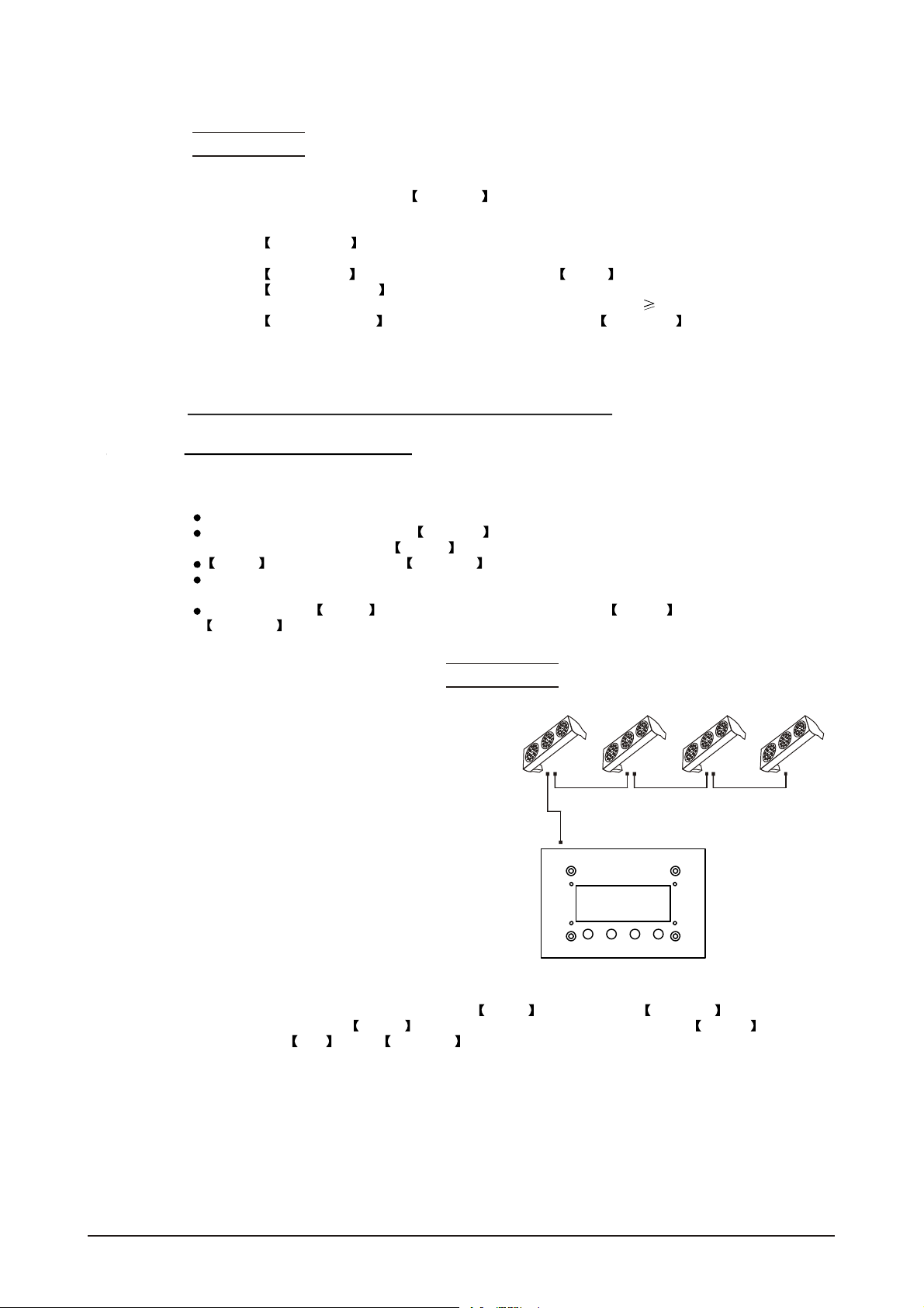
5.12 PiX CONTROLLER EXTERNAL
CONTROL VIA DMX512
It is possible to access the internal programs of thePiX controller using a DMX512 controller.
The diagram below shows how to connect the equipment together.
It is necessary to set the DMX address on the controller to the target
DMX address as selected on the DMX512 controller
DMX512
CONTROLLER
5 USING THE CONTROLLER 48
CONTROLLER
MOD E S ETUP UP DO WN
2007.9.8
Page 51

CHANNEL VALUE FUNCTION
Refresh
Wash 1
Refresh
Wash 2
Refresh
Wash 3
Refresh
Wash 4
Refresh
Wash 5
Refresh
Wash 6
Refresh
Wash 7
Refresh
Wash 8
Refresh
Effect 1
Refresh
Effect 2
Refresh
Effect 3
Refresh
Effect 4
Refresh
Effect 5
1
2
0 10
11 30
31 40
41 60
61 70
71 90
91 100
101 120
121 130
131 150
151 160
161 180
181 190
191 210
211 220
221 255
0 10
11 30
31 40
41 60
61 70
71 90
91 100
101 120
121 130
131 150
CHANNEL VALUE FUNCTION
Refresh
Effect 6
Refresh
Effect 7
Refresh
Effect 8
Refresh
Custom 1
Refresh
Custom 2
Refresh
Custom 3
Refresh
Custom 4
Refresh
Custom 5
Refresh
Custom 6
Refresh
Custom 7
Refresh
Custom 8
OFF
ON
2
3
4
151 160
161 180
181 190
191 210
211 220
221 255
0 10
11 30
31 40
41 60
61 70
71 90
91 100
101 120
121 130
131 150
151 160
161 180
181 190
191 210
211 220
221 255
0 127
128 255
5 USING THE CONTROLLER 49
2007.9.8
Page 52

6
TROUBLE SHOOTING
LED MODULE
SITUATION CAUSE PART ORDER NUMBERACTION
No display
1) Power connectionerror
2)Main PCBfuseoverheated
3) Main PCB damaged
1)Checkallpowerconnections
2) Replace fuse
3) Replace main PCB
16-03-0020-03
26-2A-LED301MV2-00
LED MODULE on,
but no control
from display
LEDs of the same
color are not lit
LEDs of all colors
are not lit
Display normal,
but no respon
se to DMX512
controller
Display board damaged Replace display board
LED PCB damaged Replace PCB board
Main PCB damaged Replace main PCB
1) Signal connection error
2) DMX addresserror
1)Checkallsignalconnections
2)CheckDMXaddresssetting
PiX CONTROLLER
SITUATION CAUSE PART ORDER NUMBERACTION
No display
Display normal,
but no response
from buttons
1) Power connectionerror
2) Power supply damaged
3) Main PCB damaged
Main PCB damaged Replace main PCB
1) Check power connections
2) Replace powersupply
3) Replace main PCB
26-2A-LED301DI-01
26-2A-LED301Light-00
26-2A-LED301MV2-00
06-08-ZB017-00
26-2A-LED301KT-00
26-2A-LED301KT-00
Display normal,
but no response
to DMX512
controller
6 MAINTENANCE 50
1) Signal connection error
2) DMX addresserror
1)Checkallsignalconnections
2) Check DMX address
2007.9.8
 Loading...