

Page 1
LED
MANAGER
DMX COMPATIBLE
300Watt LED POWER SUPPLY
WWW.BEGLEC.COM
Copyright © 2006 - 2007 by BEGLEC cva.
Reproduction or publication of the content in any manner, without express permission of the publisher, is prohibited.
Version: 1.2
Operation Manual
Mode d'emploi
Gebruiksaanwijzing
Bedienungsanleitung
Manual de instrucciones
Manual do utilizador
EN
FR
NL
DU
ES
PT
Page 2
EN - DISPOSAL OF THE DEVICE
Dispose of the unit and used batteries in an environment friendly manner
according to your country regulations.
FR - DÉCLASSER L’APPAREIL
Débarrassez-vous de l’appareil et des piles usagées de manière écologique
Conformément aux dispositions légales de votre pays.
NL - VERWIJDEREN VAN HET APPARAAT
Verwijder het toestel en de gebruikte batterijen op een milieuvriendelijke
manier conform de in uw land geldende voorschriften.
DU - ENTSORGUNG DES GERÄTS
Entsorgen Sie das Gerät und die Batterien auf umweltfreundliche Art und
Weise gemäß den Vorschriften Ihres Landes.
ES - DESHACERSE DEL APARATO
Reciclar el aparato y pilas usadas de forma ecologica conforme a las
disposiciones legales de su pais.
PT - COMO DESFAZER-SE DA UNIDADE
Tente reciclar a unidade e as pilhas usadas respeitando o ambiente e em
conformidade com as normas vigentes no seu país.
Page 3
ENGLISH OPERATION MANUAL
ENGLISH OPERATION MANUAL
Thank you for buying this JB Systems product. To takefull advantage ofall possibilities, please read these
operatinginstructions verycarefully.
FEATURES
This unitis radio-interferencesuppressed.This product meets the requirements of thecurrent European and
national guidelines. Conformity has been establishedand therelevantstatements and documentshave been
deposited by themanufacturer.
Extremely versatile power supplyforallkinds of passive RGBLED-projectors.
Different standaloneworking modes:
Fixed colormode: Instant access to9 pre-programmedcolors
Static chasemode: 12 different color chaseswith manual speed control
Sound chase mode: 12different color chaseswithaudiotriggering
Spectrum mix: 32different spectrum mix colors, including nice color fades
Adjustable speed and dimmingwith faders
Slow color fades withadjustable fade time
Blackout and “Full on”function
All functionscan be controlled directly onthe on theLED-Manageror by the optionalLEDCON-01 remote.
Several LED-Managerscan be used in Master/slave mode tocreate high power, fully synchronizedsetups.
300Watt power: 2x 150W 24Vdc outputs. (R+G+B) withshort-circuitprotections
Built-in Clock with batterybackup and NiMH batterycharger (batteries not included)
3 independent programmableon/offtimers.(start/stop 3 different color chases at 3 differenttimes!)
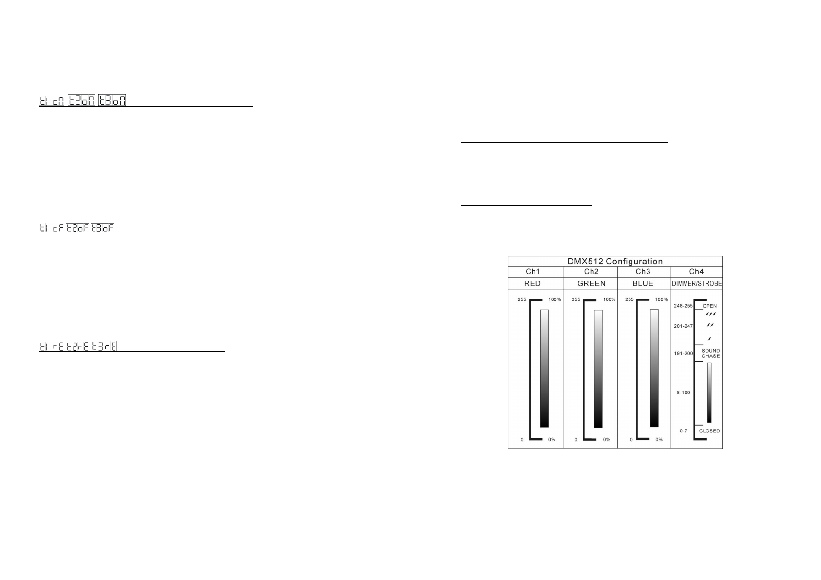
Can becontrolledby any standard DMXcontroller!
4 DMXchannelsneeded: Ch1=red,Ch2=green,Ch3=Blue,Ch4=Dimmer/strobe.
Enclosureprepared for easy installing againstthe wall.
Fan cooling for extra reliability.
BEFORE USE
Check the contents:
Check that thecartoncontains the following items:
LED-Manager
Mains cable
User manual
Some important instructions:
Before you start using this unit, pleasecheck if there’s no transportation damage.Should there be any, do
not use thedevice and consult your dealerfirst.
Important:
for the user to strictly follow thesafety instructions and warnings in this user manual. Any damagecaused
bymishandling is not subjectto warranty. The dealer will not accept responsibility forany resulting defects
orproblems caused bydisregardingthis user manual.
Keep this booklet in a safe place for future consultation. If you sell the fixture, be sure to add this user
manual.
Toprotectthe environment,pleasetry to recyclethepacking material as much as possible.
This device left our factory in perfect condition and well packaged. It is absolutely necessary
SAFETY INSTRUCTIONS:
CAUT ION
The lightning flash with arrowhead symbol within the equilateral triangle is intended to alert the use
or the presence of un-insulated “dangerous voltage” within the product’s enclosure that may be of
sufficient magnitude to constitutea risk ofelectricshock.
The exclamation point within the equilateral triangle is intended to alert the user to the presence of
important operation and maintenance (servicing) instructions in the literature accompanying this
appliance.
This symbol means: indoor use only.
Toprevent fire or shockhazard, do notexposethis appliance to rain or moisture.
To avoid condensation to be formed inside, allow theunit to adapt tothe surrounding temperatures when
bringing it into a warm room after transport. Condense sometimes prevents the unit from working at full
performance or may even cause damages.
Thisunit is forindoor use only.
Don’t place metal objects or spill liquid inside the unit. No objects filledwith liquids, suchas vases, shall be
placed on this appliance. Electric shock or malfunction may result. If a foreign object enters the unit,
immediately disconnect the mainspower.
No nakedflamesources,such aslighted candles,should beplacedon the appliance.
Don’t cover any ventilation openings as thismayresult inoverheating.
Prevent usein dusty environments and clean the unit regularly.
Keep theunit away fromchildren.
Inexperiencedpersons should not operate this device.
Maximum save ambient temperature is 45°C. Don’t use this unit athigher ambient temperatures.
Always unplug the unit when itis notused for a longertime or before you start servicing.
Theelectrical installation should be carried out by qualified personal only, according to the regulations for
electricaland mechanical safety in your country.
Check thatthe available voltage is not higher thanthe one stated on therear panel ofthe unit.
Thesocketinlet shall remain operablefor disconnection from themains.
Thepowercord should always be in perfect condition: switchthe unitimmediately off whenthe power cord
is squashed or damaged.
Never let thepower-cord come into contact with other cables!
In order to prevent electric shock, do not open the cover. Apart from the mains fuse there are no user
serviceablepartsinside.
Never
repair a fuse or bypass the fuse holder.
type and electrical specifications!
In theevent of serious operating problems, stop using the appliance and contactyourdealer immediately.
Please use the original packing when thedevice is tobe transported.
Dueto safetyreasons it is prohibited tomakeunauthorizedmodificationsto theunit.
CAUTION: To reduce the risk of electric shock, do not remove the top cover.
No user-serviceable parts inside. Refer servicing to qualified service
personnelonly.
Always
replace a damaged fuse with a fuse ofthe same
MAINTENANCE
Clean bywiping witha polished cloth slightly dippedwith water. Avoid getting waterinside the unit. Donot
use volatile liquids such as benzeneorthinner which willdamagethe unit.
Since this unit uses a cooling fan, the interior of the device should be cleaned annually using a vacuum
cleaneror air-jet.
Attention: We stronglyrecommendinternalcleaning to be carried out by qualified personnel!
JB SYSTEMS® 1/55 LED MANAGER
JB SYSTEMS® 2/55 LED MANAGER
Page 4
ENGLISH OPERATION MANUAL
ENGLISH OPERATION MANUAL
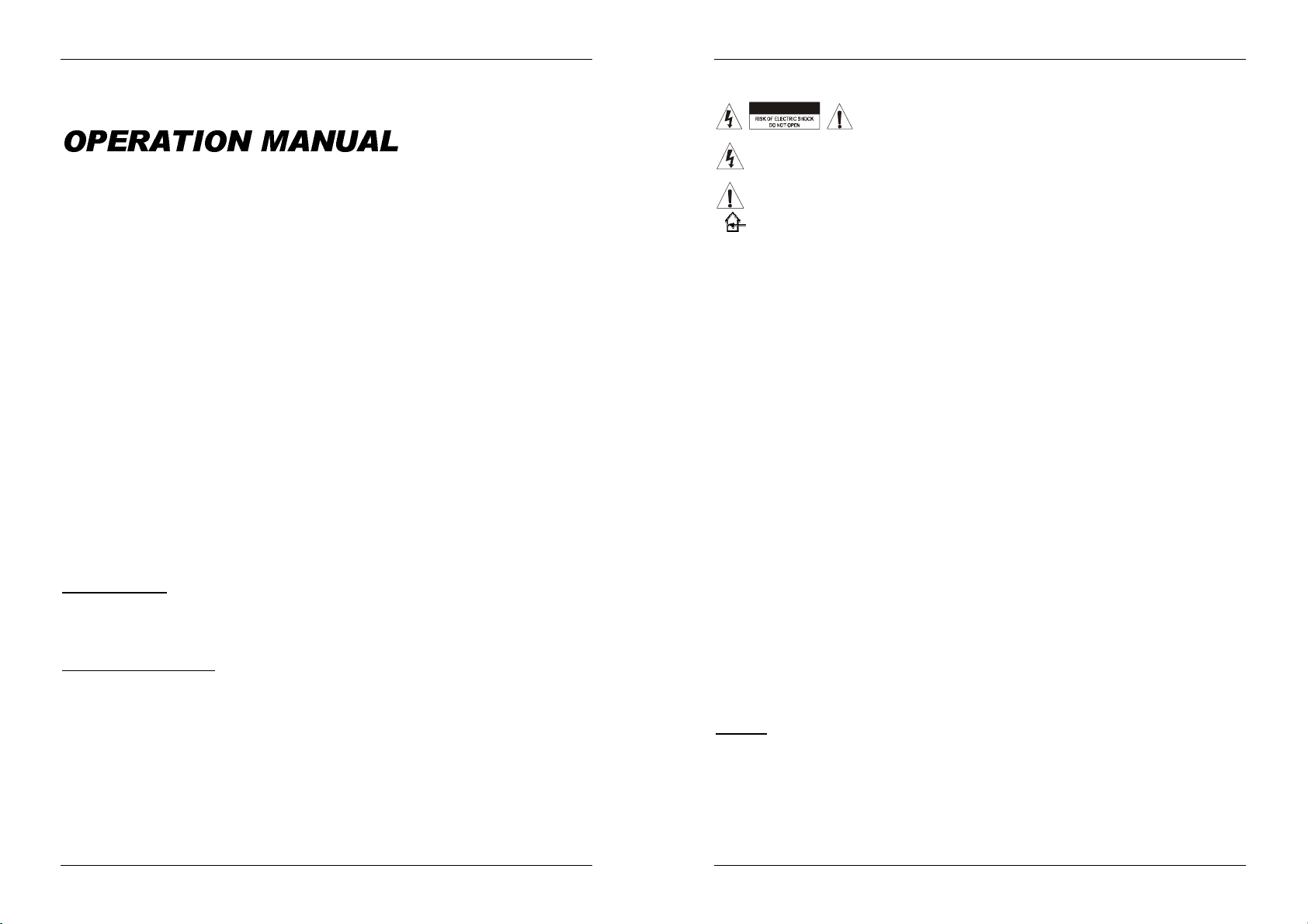
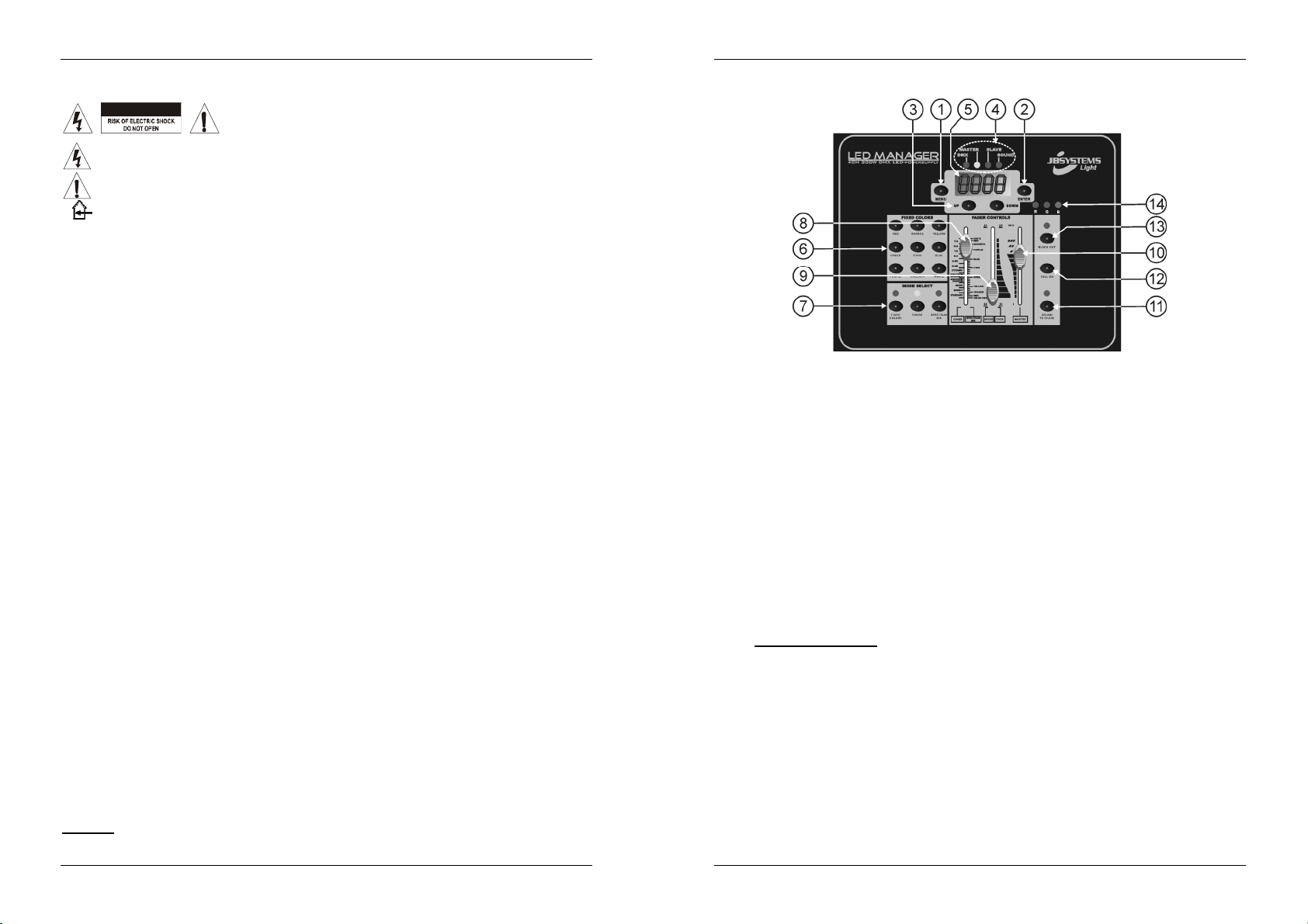
FUNCTIONS (FRONT)
1. MENU BUTTON: used toenter/leave the main menu. To return from the main menu toclockdisplay just
press the menu button for1second.
2. ENTER BUTTON: used toconfirm yourchoicein themenu.
3. UP/DOWN BUTTONS: used to browse through the mainmenuand adapt thevalues of a function.
4. STATUS MONITOR: indicates some important working conditions:
DMX-LED: indicates that theunitis workingin DMXmode. (a DMX-signalis detected)
MASTERLED: indicates that the unit is working in master mode.
SLAVE LED: indicates that theunit is working inslave mode.
SOUND LED: indicatesthat a musicsignal ispickedup by theinternal microphone.
5. DISPLAY: 4digit LED displayshows different menu options and real-time clock.
6. FIXED COLOR BUTTONS: 9 buttonseach with apresetcolor.
7. MODE SELECT BUTTONS: 3 buttons used toset the controller in differentworking modes:
FIXED COLORS: select this modeif you wantto use the“fixed color” buttons(6).
CHASE MODE: select this mode if you want to select one of the 12 color chases using the
“chase/color”fader (8).
SPECTRUM MIX: select this mode if you want to select one of the 32 different colors using the
8. CHASE/COLORFADER: used to selectone of the available color chases:
9. SPEED/FADEFADER: used toselect the chase speed or color fade time:
10. MASTERFADER: used tocontrol the overall dimming of theLEDs andoverallstrobespeed.
11. SOUND BUTTON: used totogglethe chase mode between sound and static mode.
12. FULL ON BUTTON: usedto set the 3 colors (R+G+B)atmaximum level.
13. BLACKOUT BUTTON: used toset the 3 colors (R+G+B) atzero level.
14. OUTPUT MONITOR: indicatesthe output levelsfor the 3 colors(R+G+B)
“chase/color”fader (8).
Left side of the fader indicates the different chases.
Right side of the faderindicates the differentcolors.
Importantremark: There’s also a functioncalled “colorfade” whichis very nice for “background
lighting” applications. Select this function to fade gently from one color to another. You can adjust
the fade-over time withthe speed/fade fader(9).
Left side ofthe faderindicatesthe chasespeed, ranging from 2,5s to 0,1s.
Right sideof the fader indicatesthe color fade time, ranging from12s to 2,5s.
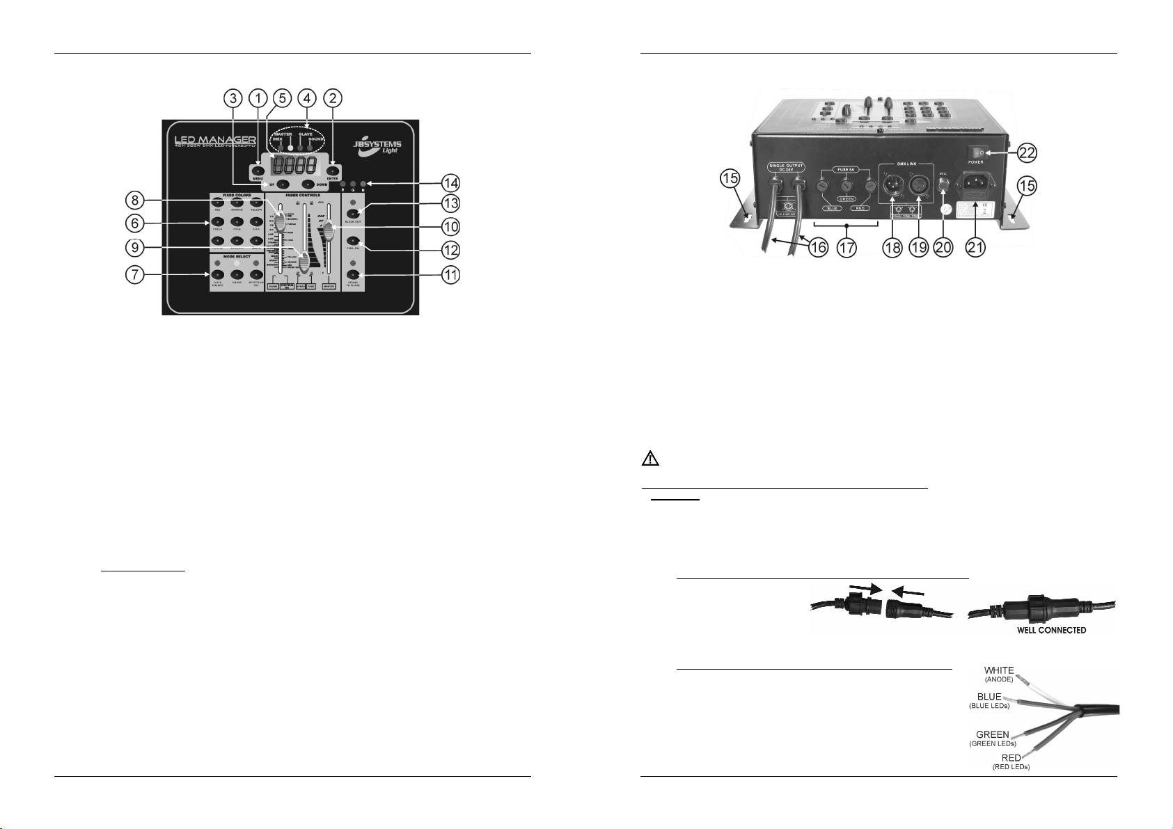
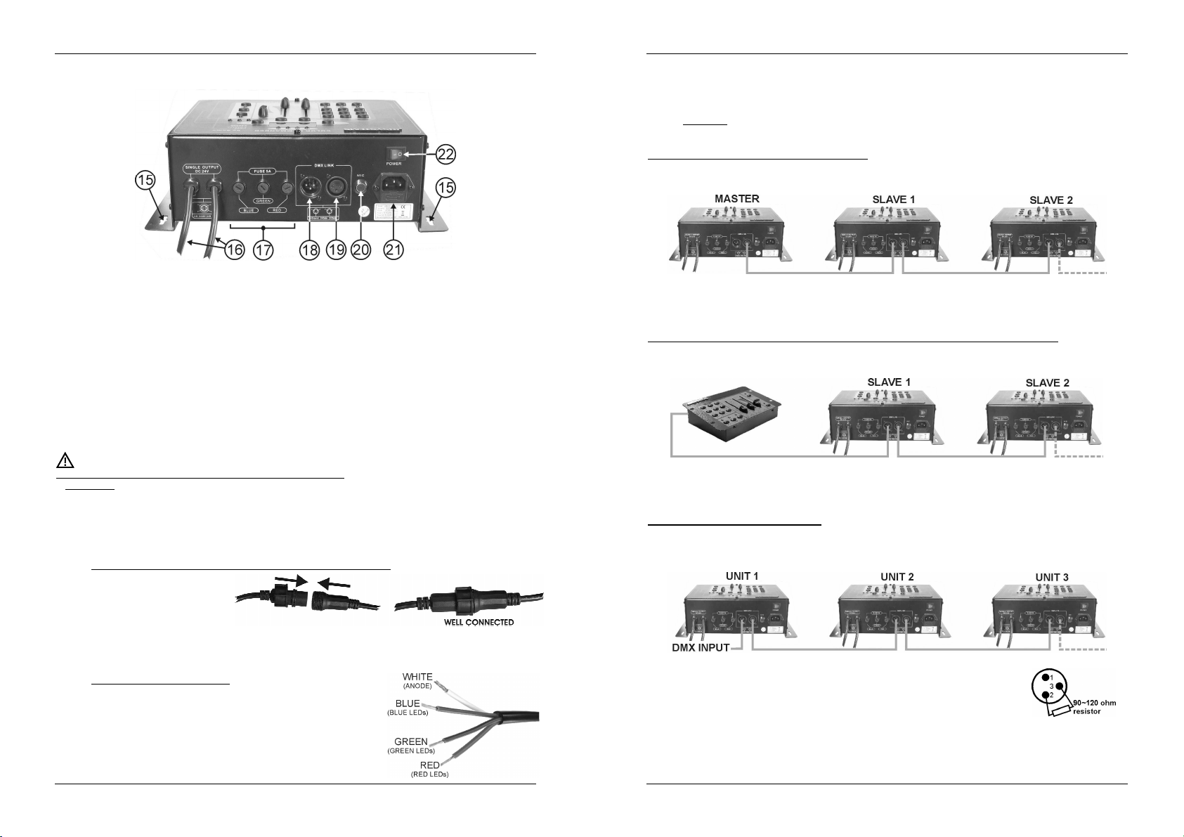
FUNCTIONS (REAR)
15. FIXING HOLES: used tofixthe unit ona wall or other flatsurface.
16. OUTPUT CABLES: used to connect different 24Vdc common anodeLED projectors. (max. load: 300W)
Each cable usesa special4pin femaleconnector.
17. OUTPUT FUSES: 6,3A fuses oneach of the3 color outputs.
18. DMX INPUT: 3pin male XLR-connector used to connect universal DMX-cables. This input receives
instructionsfrom a DMX-controller or fromanother LED-Managerwhen used inmaster/slavemode.
19. DMX OUTPUT: 3pin female XLR-connector used to connect the LED-Manager with the next DMX
appliancein thechain or with another LED-Manager when used in master/slavemode.
20. INTERNAL MICRO: used forsound activated chases.
21. MAINS INPUT: withIECsocket and integrated fuse holder, connect the supplied mains cablehere.
22. ON/OFFSWITCH: used to switchthe unit on/off.
ELECTRICAL INSTALLATION
The electrical installation should be carried out by qualified personal only, according to the
regulationsfor electricaland mechanical safety in your country.
How toconnect the LED-projectors tothe outputs of theunit:
Important: Switch theLED-manager OFF before you install theLED-projectors! The maximum total
load of the LED Manager is 300W, spread over 3 colors: each of the 3 colors has a max. load of
100W! The total load is distributed over the 2 output cables. This means that each output cable
supports 150W (max.50W foreach color!) to have a total maximum load of 300Watt. Make sure not
to overload one of the outputcables!
The 2 output cables (16) use a special 4pin connector. Two different types of passive LED projectors can
be connected:
A. LEDProjectors with a special 4pin connector (ex. LED STRIP):
This is the easiest way to
make the connections. Fix
all projectors properly and
daisy chain their in/output
cables until you reach the
maximumallowed load. Makesure tofastenthe plasticring of the connector.
Example: you canconnect up to fifteen“1m LED STRIP” on each output cable(total= 30m!)
B. LED Projectors with open wires (ex.LED GROUNDLIGHT):
In this case we suggest to take a 1m extension cable (with
special male/female 4pin connectors) and to cut the female
connector. Now you can easily strip the cable. You will find 4
coloredwiresinside:
Whitewire: Thisis the commonwire (anode)
Red wire: This the power for the redLEDs (max. 50W)
Greenwire: Thisthe power for the greenLEDs (max.50W)
JB SYSTEMS® 3/55 LED MANAGER
JB SYSTEMS® 4/55 LED MANAGER
Page 5
ENGLISH OPERATION MANUAL
ENGLISH OPERATION MANUAL
Bluewire: This the power for theblue LEDs (max.50W)
Just connect these 4 wiresto thecorresponding 4 wires of theprojector.(in mostcases the colors of
thewires matchwith the LED colors)Make sure not to exceed the maximumallowed load!
Example: you canconnect up to 50 “GROUND LIGHT” on each output cable (total = 100pcs!)
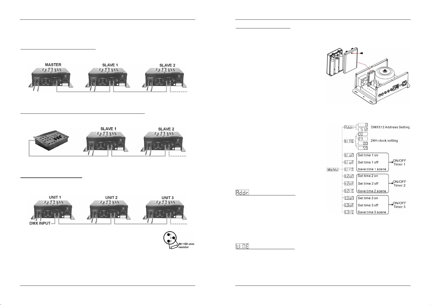
ElectricalinstallationinMaster/slave-mode:
You need to “daisy chain” the DMXin/outputs of 2 or more unitswith a good quality balanced cable (ex.
JB Systems ref. 7-0063).
The unit with a free DMX-input connectorautomaticallybecomes the master (master LED islit), the other
units areautomatically switched asslaves (slave LED is lit). The controls on the slaveunits are disabled.
ElectricalinstallationinMaster/slave-mode with the LEDCON-01 remote:
You need to “daisy chain” the DMX in/outputs of 1 or more units with the output of the LEDCON-01
remoteusing a good quality balanced cable (ex. JB Systems ref. 7-0063).
The LEDCON-01 remote will be used to control all connected slaves. The LED Managers are
automatically switched as slaves(slaveLED is lit).The controls onthe slave units are disabled.
Electrical installation in DMX-mode:
The DMX-protocol is a widely used high speed signal to control intelligent light equipment. You need to
“daisy chain” your DMX controller and allthe connected units with a good quality balanced cable(ex. JB
Systems ref. 7-0063).
To prevent strange behavior of the light effects,due tointerferences, youmust use
a 90Ω to 120Ω terminator at the end of the chain. Neveruse Y-splitter cables, this
simply won’t work!
Each unit in the chain needs its proper startaddress so it knows which commands
from the DMX-controller it has to decode. When you need a lot of power you can
use several LED managers and givethem the samestart address. In the next chapter you willlearn how
to set theDMX addresses.
Changingtheinternal batteries:
VERY IMPORTANT:ONLY rechargeable batteries are allowed, do NOT use normal batteries!!!
The LED Managerhas an internal real-time 24H clock with 3 individual timers and battery backup. To use
the battery backup feature you must install 3 optional AA-type NiMH rechargeable batteries. Once these
batteriesare installed theywill be recharged automatically, no need toreplace themanymore!
Switch the unitoffand disconnect the mains cable.
Use an appropriate screwdriver to unscrew the 10
screws of the enclosure.
Gently remove the top cover (careful for thecables
inside!)
On the inside you will find a battery compartment,
nextto thefan. Open it gently and install the3 AAtype NiMH rechargeable batteries as indicated.
Close the battery compartment
Put the top cover back in place and fasten the 10
screws.
Connect the unit to the mains: the batteries will
charge automatically.
Done!
SETUP MENUS + DMX ADDRESSING
During normal operation the display shows the current
timeof the internal 24H clock.
Press theMENU buttonto entermenu mode:
With the UP and DOWN buttons you can browse
throughthe different options ofthe main menu.
Press the ENTER button to select and edit a menu
option.
Adapt the values with the UP & DOWN buttons and
confirm with the ENTER button or press the MENU
button again if you want to return to the main menu
withoutsaving thechanges you justmade.
After some time the display will automatically show
the internal clock. You can also switch to the clock
display by pressing the MENU button for about 1
second.
DMX startaddress setting
Used to setthe start address ofthe LED Manager.
Press theMENU button and UP/DOWNbuttons until
thedisplay shows“Addr”
Press theENTER button: the displaystarts blinking.
Use the DOWN and UP buttons to changethe DMX
address.
Once thecorrectaddress isshown onthe display, pressthe ENTER button tosave it.
Remarks: You canabort thesetting procedure and goback without savingthe changes byshortlypressing
the MENU button. When the setup is done and changes are saved,you can return to the clock display by
pressing the MENUbutton for more than1second.
Internal24H clock setting
Used to set the time ofthe internal24H clock.
Press theMENU button and UP/DOWN buttons untilthe display shows “time”
Press theENTER button, the HOUR-display starts blinking.
Use the DOWN and UPbuttons to set the correct hours (00 to 23).
Press theENTER button, the MINUTE-display starts blinking.
Use the DOWN and UPbuttons toset thecorrect minutes(00 to59).
JB SYSTEMS® 5/55 LED MANAGER
JB SYSTEMS® 6/55 LED MANAGER
Page 6
ENGLISH OPERATION MANUAL
ENGLISH OPERATION MANUAL
Once the correct time is shown, press the ENTER button. The new clock settings are saved while the
display shows “time”
Remarks: You canabort thesetting procedure and go back without savingthe changes by shortly pressing
the MENU button. When the setup is done and changes are saved, you can return to the clock display by
pressing the MENUbutton for more than1second.
ON/OFFTimers “START-time” setting
The LED Manager has 3 individual ON/OFF timers. So you areable to switch the output on/off at 3 different
parts of the day, each time with a different color or color chase. Below we explain how to set the start-time
for“ON/OFF timer1”. The settings for the other 2 timers areidentical.
Press theMENU buttonand UP/DOWN buttons untilthe display shows“t1on”
Press theENTER button, the HOUR-display starts blinking.
Use the DOWN and UPbuttons to set the correct hours (00 to 23).
Press theENTER button, the MINUTE-displaystarts blinking.
Use the DOWN and UPbuttons toset thecorrect minutes(00 to59).
Once the correct start time is shown, press the ENTER button. The new start time is saved while the
display shows“t1on”
Remarks: You can abortthe setting procedure and go backwithout saving the changes by shortlypressing
the MENU button. When the setup is done and changes are saved, you can return to the clock display by
pressing the MENUbutton for more than1second.
ON/OFF Timer “STOP-time” setting
Below we explain how to set the stop-time for “ON/OFF timer1”. The settings for the other 2 timers are
identical.
Press theMENU buttonand UP/DOWNbuttons until the display shows “t1oF”
Press theENTER button, the HOUR-display starts blinking.
Use the DOWN and UPbuttons to set the correct hours (00 to 23).
Press theENTER button, the MINUTE-displaystarts blinking.
Use the DOWN and UPbuttons toset thecorrect minutes(00 to59).
Once the correct stop time is shown, press the ENTER button. The new stop time is saved while the
display shows “t1oF”
Remarks: You can abort thesetting procedure and go backwithout saving the changes by shortlypressing
the MENU button. When the setup is done and changes are saved, you can return to the clock display by
pressing the MENUbutton for more than1second.
B. Twoor moreunitsin master/slave setup:
Connect the LEDprojectors to the LEDManagers asindicated in the previouschapters.
Connect the units witheach other as explained in the chapter about electrical installations. (noneed to
set a DMX address!
Switch the LED Managers on. You can only use the controls on the master unit, the controls on the
slaves are disabled. Refer to the chapter “Functions” to make yourself familiar with the various
functions of thefaders andbuttons on themaster unit.
In this mode you can also set the clock and use the 3 on/off timers on the master as described in the
previouschapter.
Remark:When a timerisactive, you can deactivateit by pressing the blackoutbutton.
C. Connect the optionalLEDCON-01 controller for remote control:
In most cases the LED MANAGER will be installed on a wall, close to the LED-projectors. If you want to
have easy access to its functions, you can connect the LEDCON-01 remote controller to the (first) LED
Manager. The otherconnections are identical to those ofthe standalone or master/slave setups.
Except for thedisplay, internal 24H clock and the 3 on/offtimers, the controls on the remote are identical
to that of the LED Manager. So please refer tothe chapter “Functions” tomake yourself familiar with the
variousfunctions ofthe faders and buttons.
D. Controlledby universal DMX-controller:
Connect the LEDprojectors to the LEDManager(s) as indicatedin the previouschapters.
Connect the LED Manager(s) with allother DMX-appliances in theDMX-chain.
Switch all unitson and set the proper DMX-addresses. (DMX-LED on the LED Manager is lit)
Switch your universal DMX-controller on and refer to the DMX chart below to control the connected
LEDmanagers:
ON/OFF Timer “SCENE” setting
Below we explain how to select the scene (color or color chase) for “ON/OFF timer1”. The settings for the
other 2 timers areidentical.
Press theMENU buttonand UP/DOWNbuttons until the display shows“t1rE”
Press theENTER button, thedisplay starts blinking.
Now you havethe time to set thescene that youwould like toreproduce when the timeris activated.
When the sceneis OK(don’t forgetto switch the blackout function off!) justpressthe ENTER buttonagain.
The display stops blinking and the scene is saved.
Remarks: You can abort thesetting procedure and go backwithout saving the changes by shortlypressing
the MENU button. When the setup is done and changes are saved, you can return to the clock display by
pressing the MENUbutton for more than1second.
OPERATING INSTRUCTIONS
A. Standalone1unit:
Connect the LEDprojectors to theLED Manager asindicated inthe previous chapters. (noneed toset
a DMX address!)
Switch the unit on and refer to the chapter “Functions” to make yourself familiar with the various
functionsof the fadersand buttons.
In this mode you can also set the clock and use the 3 on/off timers asdescribed in theprevious chapter.
Remark:Whena timeris active, you candeactivateit by pressing the blackoutbutton.
JB SYSTEMS® 7/55 LED MANAGER
All controls (buttons and faders) on the LEDManager(s) are disabled, except the buttons needed to set
the DMX-address.
JB SYSTEMS® 8/55 LED MANAGER
Page 7
ENGLISH OPERATION MANUAL
SPECIFICATIONS
Power Input: AC230V~ 50Hz
Fuse: 6,3Aslow blow (20mm glass)
Backupbatteries: 3x 1,2V AA-typeNiMHrechargeable batteries (optional)
Outputvoltage to LEDs: DC 24V common anode
Outputpower to LEDs: 2x 150W max. (Total = 300W max.)
DMX connections: 3pinXLR (DMX-512standard)
DMX channels: 4 (CH1: red, CH2: green, CH3:blue, CH4:dimmer/strobe)
Audio input: None,internalmicrophone
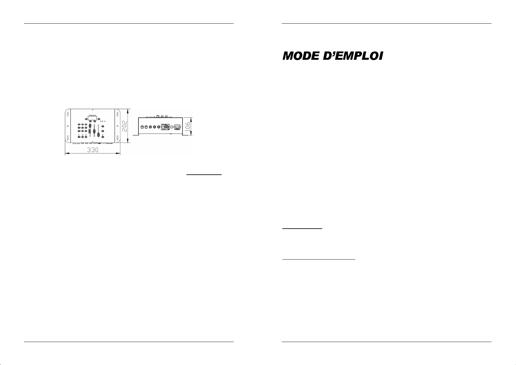
Size: 330x 202x 106cm (see drawing below)
Weight: 6,6kg
Every informationis subject tochange without prior notice
You can download the latestversion of this user manual on ourwebsite: www.beglec.com
o Red: 2x 50W max. (Total = 100W max.)
o Green: 2x50W max.(Total = 100W max.)
o Blue: 2x 50W max. (Total = 100W max.)
FRANCAIS MODE D’EMPLOI
Nous vous remercions d’avoir acheté ce produit JB Systems. Veuillez lire ce mode d’emploi très
attentivement afin de pouvoir exploitertoutes les possibilités de cetappareil.
CARACTERISTIQUES
Cet appareil ne produit pas d’interférences radio. Il répond aux exigences nationales et européennes. La
conformité aété établie et les déclarations et documents correspondants ontété déposés par le fabricant.
Alimentation polyvalentepour toutes sortesde projecteurs RVB LED passifs
Différentsmodes defonctionnement isolées:
Fixed colors mode: accès immédiat aux 9 couleurs préprogrammées
Static chasemode : 12 différentsdéfilements de couleurs avec contrôle manuel devitesse
Sound chasemode :12 différents défilements de couleurs avecdéclenchementde signalaudio
Spectrum mix : 32différentescouleurs spectrum mix,inclus des joliestransitions
Vitesseet éclairageréglables avec curseur
Transitionde couleur lenteréglable avec curseur
Fonctions ‘Black-out’ et‘fullon’
Toutes les fonctions peuventêtre contrôlées par le LED MANAGER ou par le LEDCON-01 facultatif.
Plusieurs LED MANAGERs peuvent être utilisés ensemble en mode Maître/esclave pour obtenir une
puissance élevée etentièrement synchronisé
Capacité de 300Watt :2 sorties150W 24Vdc. (protection court-circuit R+V+B)
Horloge incorporée avec backuppar pile et chargeur depile NiMH(piles pasjointes)
3 minuteriesprogrammableon/off.
Peut êtrecontrôlépar chaque contrôleur DMX standard!
4 canauxDMXnécessaires:Ch1=rouge; Ch2=vert ; Ch3=bleu ;Ch4=Dimmer/stroboscope
Le boîtier est préparé pour une l'installation facile contre le mur
Ventilateur pour unefiabilitésupplémentaire
JB SYSTEMS® 9/55 LED MANAGER
AVANT L’UTILISATION
Vérifiez le contenu:
Vérifiezsi la boite contientles articles suivants :
LED MANAGER
Câbled’alimentation
Mode d’emploi
Quelquesinstructionsimportantes:
Avant d’utiliser cet appareil, assurez-vous de l’absence de dommage lié au transport. En cas
d’endommagement,n’utilisezpas l’appareil et contactez le vendeur.
Important:
l’utilisateur suive les instructions de sécurité et avertissements inclus dans ce manuel. La garantie ne
s’applique pas en cas de dommage lié à une utilisation incorrecte. Le vendeur ne prend pas la
responsabilité des défauts ou de tout problèmerésultant du fait de n’avoir pas tenu compte des mises en
garde de cemanuel.
Conservez ce manuel dans un endroit sûr pour toute consultation future. Si vous vendez l’appareil,
assurez-vous d’y joindre ce manuel également.
Afin deprotéger l’environnement,merci de recycler les emballages autant que possible.
JB SYSTEMS® 10/55 LED MANAGER
Cet appareil a quitté notre usine en parfaite condition et bien emballé. Il est primordial que
Page 8
FRANCAIS MODE D’EMPLOI
FRANCAIS MODE D’EMPLOI
INSTRUCTIONS DE SECURITE:
CAUTION
La flèche dans un triangle met l'utilisateur en garde de la présence de haut voltage sans isolation
dans l'appareil qui peutcauser un risque d'électrocution.
Un point d'exclamation dans un triangle prévient de la présence d'instructions de fonctionnement et
de maintenance se trouvant dans lemanuel, fourniavec l'appareil.
Ce symbole signifie : uniquementpour usageà l'intérieur
Afin d’éviter tout risque d’incendie ou de choc électrique, ne pas exposer cet appareil à la pluie ou
l’humidité.
Pour éviterla formation de condensation à l’intérieurde l’appareil,patientez quelques minutes pour laisser
l’appareil s’adapter à latempérature ambiante lorsqu’il arrive dans une pièce chauffée après le transport.
La condensation empêche l’unité de fonctionner en performance optimale et peut même causer des
dommages.
Cetteunité est destinée à une utilisationà l’intérieur uniquement.
Ne pas insérer d’objet métallique ou verserun liquide dans l’appareil. Aucun objet rempli de liquides, tels
que des vases, ne sera placé sur cet appareil. Risque de choc électrique ou de dysfonctionnement. Si un
corps étranger est introduit dansl’unité, déconnectezimmédiatementde la sourced’alimentation.
Aucune sourcede flammenue, telle que les bougies allumées, ne devrait être placée sur l'appareil.
Ne pas couvrirles ouvertures de ventilation,un risquede surchauffe en résulterait.
Ne pas utiliser dans un environnementpoussiéreux et nettoyez l’unitérégulièrement.
Ne pas laisser l’unité à portéedes enfants.
Les personnes nonexpérimentéesne doivent pas utiliser cetappareil.
La température ambiante maximum d’utilisation del’appareil est de 45°C. Ne pas l’utiliser au-delà de cette
température.
Débrancheztoujoursl’appareil si vous nel’utilisez pas de manière prolongéeou avant d’entreprendre des
réparations.
Les installations électriques ne peuvent être faites que par du personnel qualifié et conformément aux
régulations de sécurité électrique et mécanique envigueur dans votrepays.
Assurez-vous que le voltage de la source d’alimentation de la zone dans laquelle vous vous trouvez ne
dépasse pas celui indiqué à l’arrièrede l’appareil.
La prise seratoujours accessible pour que le cordon secteur puisse être enlevé à chaque moment.
Le cordon d’alimentationdoit toujours êtreen conditionparfaite.Mettez immédiatement l’unité hors tension
si le cordonest écrasé ou endommagé.
Ne laissez jamais le cordond’alimentation entrer en contact avecd’autres câbles !
Utiliseztoujours les câbles appropriés etcertifiés lorsque vous installez l’unité.
Pour éviter tout choc électrique, ne pas ouvrir l’appareil. En dehors du fusible principal, il n’y a pas de
pièces pouvant être changées parl’utilisateurà l’intérieur.
Nejamais
un fusible de même typeet spécifications électriques !
En cas de problèmes de fonctionnement sérieux, arrêtez toute utilisation de l’appareil et contactez votre
revendeurimmédiatement.
Utilisezl’emballaged’origine si l’appareildoit êtretransporté.
Pour des raisons de sécurité, il est interdit d’apporter toute modification à l’unité non spécifiquement
autoriséepar les parties responsables.
réparer ou court-circuiter un fusible.Remplacez
ATTENTION: afin de réduire le risque d’électrocution, n’enlevez jamais le
couvercle del’appareil. Il n’y aaucune pièce à l’intérieur de l’appareil que
vous pouvez remplacer vous-même. Confiez l’entretien uniquement aux
techniciensqualifiés.
systématiquement
un fusible endommagé par
ENTRETIEN
Nettoyez l’appareil à l’aide d’un chiffon doux, légèrement humide. Evitez d’introduire de l’eau à l’intérieur
de l’appareil. N’utilisez pas de produits volatiles tels le benzène ou le thinner qui peuvent endommager
l’appareil.
Étant donné quecet appareilutilise un ventilateur,l’intérieur de l'appareil doit être nettoyé annuellement à
l'aide d'un aspirateurou d'air sous pression.
Attention: Nous conseillons que le nettoyageinterne se fasse par unepersonne qualifiée.
FONCTIONS (FACE AVANT)
1. BOUTON MENU: Utilisé pour consulter ou quitter lemenu principal. Pour retournerdu menu principal à
l'affichagede l’horloge appuyez 1 seconde sur lebouton menu.
2. BOUTON ENTER: Pourconfirmer la fonction sélectionnée.
3. BOUTON UP/DOWN: Pour feuilleterdansle menu principal et sélectionnerles valeurs d'une fonction.
4. MONITEUR STATUS:Indiquequelques fonctions importantes:
LED DMX:Indique que l'appareil fonctionne en modeDMX.(un signalDMX est détecté).
LED MASTER: Indique quel'appareil fonctionne en mode maître.
LED SLAVE: Indique quel'appareil fonctionneen mode esclave.
LED SOUND: Clignote au rythme de lamusique, détecté par lemicro intégré.
5. ÉCRAN: écran 4digit LED, affiche les différentesoptions menu.
6. BOUTONS FIXED COLOR: 9 boutons, chacun avecune couleur préprogrammé.
7. BOUTONS MODE SELECT: 3 boutons pour placer le contrôleur sur différentes méthodes de
fonctionnement:
FIXED COLORS: Sélectionnez ce mode, sivous voulez utiliser lesboutons‘fixed color’.
CHASEMODE: Sélectionnez ce mode,si vousvoulez utiliser un des 12 défilementde couleur en
utilisantle curseur ‘chase/color’ (8).
SPECTRUM MIX: Sélectionnez ce mode, si vous voulez utiliser une des 32 couleurs différentes
8. CURSEURCHASE/COLOR: Utilisé pour sélectionnerun desdéfilement decouleur disponible:
9. CURSEURSPEED/FADE: Utilisé pour sélectionné lavitesse de transition ou letemps color fade.
10. CURSEUR MASTER: Utilisé pour régler la puissance de sortie vers les projecteurs LED et pour
11. BOUTONSOUND: Pour inverser le mode chaseentre sound etstatic mode.
12. BOUTONFULL ON: Pour placer les 3 couleurs(R+G+B) au niveau max.
13. BOUTON BLACKOUT: Pour placer les 3couleurs (R+G+B) au niveau zéro.
14. SORTIE MONITEUR: Indique le niveau sortie des 3couleurs (R+G+B).
en utilisant le curseur‘chase/color(8).
Le côté gauche du curseurindique les différents défilements.
Le côté droitsdu curseur indique les différentescouleurs.
Remarque importante: Il y a une fonction ‘color fade’ qui est très joli pour un éclairage d’arrière
plan. Sélectionnez cette fonction pour passer progressivement d’une couleur vers une autre. Vous
pouvezadapter lapériode de transition avec le curseur‘speed’(9).
Le côté gauche du curseurindique lavitessede transition, de 2,5sà 0,1s.
Le côté droits du curseur indique le temps colorfade, de 12s à 2,5s.
contrôler la vitesse du stroboscope.
JB SYSTEMS® 11/55 LED MANAGER
JB SYSTEMS® 12/55 LED MANAGER
Page 9
FRANCAIS MODE D’EMPLOI
FRANCAIS MODE D’EMPLOI
FONCTIONS (arrière)
15. TROUSDE FIXATION: Pour fixer l’appareil sur un mur ou sur une autresurface plate.
16. CABLES DE SORTIE: Les câblesd’alimentation pour les projecteursLED.
Chaque câble utiliseun connecteur femelle 4pin.
17. FUSIBLES: Fusibles 6,3Asur les3 sorties couleur.
18. ENTRÉE DMX: Connecteur XLR 3pin mâle permet de connecter des câbles DMX. Cette entrée reçoit
des instructions provenant d’un contrôleurDMX ou, en modemaster/slave, d’un autre LED MANAGER.
19. SORTIE DMX: Connecteur XLR 3pin femelle permet de connecter le LEDMANAGER à l’unité suivante
de la chaîneDMXou à un autreLEDMANAGER en mode master/slave.
20. MICROPHONEINTERNE: microintégré.
21. ALIMENTATION SECTEUR D’ ENTRÉE: avec une prise IEC avec fusible incorporé, connectez les
câbles d’alimentations fournis danscette prise.
22. INTERRUPTEURON/OFF: utilisé pourallumer/éteindrel’appareil.
INSTALLATION ÉLECTRIQUE
L’installation électrique doit être faite uniquement par une personne qualifiée et selon les
règlements pour la sécurité électriqueet mécanique dans votre pays.
Commentrelier lesprojecteurs LED auxsorties de l'appareil:
Important: Coupez le LED MANAGER avant d’installer lesprojecteurs LED!La chargemaximale du
LED MANAGER est 300W, répartie en 3 couleurs: chacune des 3 couleurs a une charge maximale
de 100W! Toute la charge est répartie sur les 2 câbles de sortie. Ceci signifie que chaque câble
supporte 150W (max. 50W pour chaque couleur!)pour avoir la charge totale maximalede 300Watt!
Veuillezne pas surcharger un des câbles de sortie.
Les 2 câblesde sortie (16) utilisent un connecteurspécial 4pin. Deuxtypes de projecteurspassifs LED
peuventêtre reliés:
A. Projecteurs LED avec connecteurspécial4pin(ex. LED STRIP):
C'est la manière la plus facile
d'établir les connections.
Fixez correctement tous les
projecteurs en reliant les
câbles d'entrée/sortie de
chaque appareil jusqu'à ce que vous atteignez la charge maximale permise. Veillez à attacher
l'anneau en plastiqueaux connecteur.
Exemple:Vous pouvezrelier jusqu'à quinze ‘1mLED STRIP’sur chaquecâble de sortie (total=
30m!).
B. Projecteursavec filsouverts:
Dans ce cas-ci, nous suggérons de prendre une rallongede 1m
(avec connecteur 4pin mâle/femelles) et d’enlever le connecteur
femelle. Maintenant vous pouvez facilement dénuder le câble.
Vous trouverez4 fils colorés à l’intérieur:
Fil blanc:Le fil commun (l’anode)
Fil rouge:La puissance pour les LED rouges (max. 50W)
Fil vert: Lapuissance pourles LED verts(max. 50W)
Fil bleu:La puissance pourlesLED bleus(max.50W)
Reliez juste ses 4 fils aux 4 fils correspondants du projecteur. (dans la plupart des cas les couleurs
des fils correspondent aux couleurs desLED) veuillez ne pas dépasser la chargemaximalepermise!
Exemple: Vous pouvez relier jusqu'à 50 ‘GROUND LIGHT’ sur chaque câble de sortie
(total= 100pcs!)
Installationélectriqueen mode maître/esclave:
Vous devezrelierles entrées/sorties DMX de2 ou plusieurs appareils avec un bon câble symétrique (ex.
JB Systems réf.7-0063).
L’appareil avecune entrée DMX libre devient automatiquement lemaître(le LED masterest allumé),les
autres appareils deviennent automatiquement esclave (le LED slave est allumé). Les commandessur
l’appareil esclave sont horsservice.
Installationélectrique en mode maître/esclave aveccommandeà distance LEDCON-01:
Vous devez relier les entrées/sorties DMX d’un ou plusieurs appareils avec la sortie du LEDCON-01
avec un boncâble symétrique (ex. JB Systemsréf. 7-0063).
La commande à distanceLEDCON-01 sera utilisée pour commander tout les esclaves reliés. Les LED
MANAGERs sont automatiquement mis en mode esclaves (le slave LED est allumé). Les commandes
sur les appareils esclavesont horsservice.
Installationélectrique en mode DMX:
Le protocole DMX est largement employé, c’est un signal à grande vitesse pour commander
l'équipement lumière. Vous devez relier votre contrôleur DMX et tous les appareils, avec un bon câble
symétrique (ex. réf. Systèmes7-0063).
Afin d’éviter que vos effets de lumière se comportent de manière étrange, à
cause d’interférences, utilisez des bouchons de 90Ω à 120Ω en fin de chaîne.
N’utilisez jamais descâbles de dérivation,ceci ne fonctionnepas!
Chaque appareil dans la chaîne nécessite sa propre adressede démarrage afin
de savoir quelles commandes du contrôleur DMX il doit décoder. Si vous avez
besoin de beaucoup de puissance, vous pouvezemployer plusieurs LED MANAGERs et leur donner la
même adresse de démarrage. Dans le prochain chapitre, vous apprendrez comment installer les
adressesDMX.
JB SYSTEMS® 13/55 LED MANAGER
JB SYSTEMS® 14/55 LED MANAGER
Page 10

FRANCAIS MODE D’EMPLOI
FRANCAIS MODE D’EMPLOI
Changer les piles internes:
TRÈS IMPORTANT: SEULEMENT des piles rechargeables sont permises, n'utiliser pas des piles
normales!!!
Le LED MANAGER possède une horloge 24H interne avec 3 minuteries individuelles et une pile de
sauvegarde. Pour employer la pile de sauvegarde vous devez installer 3 piles rechargeables de type AA
NiMH. Une fois les piles installées elles seront rechargées automatiquement, aucun besoin de les
remplacer!
Coupez l’appareil et débranchez le câble
d’alimentation.
Utilisez un tournevis approprié pour dévisser les
10 vis du boîtier.
Enlevez doucement la couverture supérieure
(soyezprudent pour lescâbles à l'intérieur!).
À l’intérieur, à côté du ventilateur, vous trouverez
le compartimentde piles.
Ouvrez-le doucement et installez les piles
rechargeablestype AA NiMH comme indiqué.
Fermez le compartiment de pile.
Remettez la couverture supérieure en place et
attachezles 10 vis.
Branchez l’appareil sur une prise: les piles se
chargerontautomatiquement.
Fini!
INSTALLATION DES MENUS + ADRESSAGE DMX
Pendant l'opération l’écran montre le temps de
l'horloge interne24H.
Appuyez sur le bouton MENU pour entrer dans le
mode menu:
Avec les boutons UP/DOWN vous pouvez
chercher dans les différentes options du menu
principal.
Appuyez sur le bouton ENTER pour sélectionner
et éditer une optiondu menu.
Adaptez les valeurs avec les boutons UP &
DOWN et confirmez avec le bouton ENTER.
Appuyez sur le bouton MENU si vous souhaitez
retourner aux menu principal sans sauvegarder
leschangements.
Après un certain temps,, l’écran montrera
automatiquement l’horloge interne. Vous pouvez
également retourner vers l’écran de l’horloge en
appuyant sur le bouton MENU pendant1 seconde.
Ajustementdel’adresse DMX
Utilisé pour ajuster l’adresse de démarrage du LED
MANAGER.
Appuyez sur lestouches MENU et UP/DOWN jusqu’à ce que ‘Addr’soit affiché àl’écran.
Appuyez sur la touche ENTER, l’écran commence à clignoter.
Utilisez les touchesUP et DOWNpour changer l’adresseDMX.
Quand l’adresse désirée est affichée à l’écran, appuyez sur la touche ENTER pour confirmer votre
choix.
REMARQUES: Vous pouvez interrompre la procédure et retourner aux fonctions sans effectuer de
changements, en appuyant à nouveau brièvement la touche MENU. Quand l'installation est faite et les
changements sont sauvés, vous pouvez retourner à l'écran de l’horloge en appuyant sur la touche MENU
pendantplusd’une seconde.
Réglage horlogeinterne 24H
Utilisepour régler le temps de l’horlogeinterne24H
Appuyez sur les touches MENU etUP/DOWN jusqu’à ce que ‘time’ soit affiché à l’écran.
Appuyez surla touche ENTER, l’écran HEURE commenceà clignoter.
Utilisez les touchesUP etDOWN pour introduire l’heureexacte(00 à 23).
Appuyez sur la touche ENTER, l’écran MINUTEcommenceà clignoter.
Utilisez les touchesUP etDOWN pour introduire lesminutes exactes (00 à59).
Une foiele tempscorrecte affiché, appuyez sur la touche ENTER. Lesnouveauxréglages d’horloge sont
sauvées et que l’écran affiche ‘time’.
REMARQUES: Vous pouvez interrompre la procédure et retourner aux fonctions sans effectuer de
changements, en appuyant à nouveau brièvement la touche MENU. Quand l'installation est faite et les
changements sont sauvés, vous pouvez retourner à l'écran de l’horloge en appuyant sur la touche MENU
pendantplusd’une seconde.
Le LED MANAGER possède 3 minuteries individuelles ON/OFF. Vous pouvez allumer/éteindre les sorties à
3 moments de la journée, chaque fois avec une couleur ou un défilement de couleur différent. Au-dessous
nous vous expliquons comment mettre le temps de démarrage pour la ‘minuterie1 ON/OFF’. Lesréglages
pour les 2 autresminuteriessont identiques.
Appuyez sur lestouchesMENU et UP/DOWN jusqu’à ce que ‘t1on’soit affiché à l’écran.
Appuyez sur latoucheENTER, l’écran HEUREcommenceà clignoter.
Utilisez les touchesUP etDOWN pour introduire l’heureexacte(00 à 23).
Appuyez sur la touche ENTER, l’écran MINUTEcommenceà clignoter.
Utilisez les touchesUP et DOWN pour introduire lesminutes exactes(00 à59).
Une fois que le temps de démarrage correct est affiché, appuyez sur la touche ENTER. Le nouveaux
tempsde démarrage est sauvé pendant que l’écran affiche‘t1on’.
REMARQUES: Vous pouvez interrompre la procédure et retourner aux fonctions sans effectuer de
changements, en appuyant à nouveau brièvement la touche MENU. Quand l'installation est faite et les
changements sont sauvés, vous pouvez retourner à l'écran de l’horloge en appuyant sur la touche MENU
pendantplusd’une seconde.
Ci-dessous, nous vous expliquons comment mettre le temps d’arrêt pour la ‘minuterie1 ON/OFF’. Les
réglages pour les2 autres minuteriessont identiques.
Appuyez sur lestouchesMENU et UP/DOWN jusqu’à ce que ‘t1oF’soit affiché à l’écran.
Appuyez sur la touche ENTER,l’écran HEURE commence à clignoter.
Utilisez les touchesUP etDOWN pour introduire l’heureexacte(00 à 23).
Appuyez sur la touche ENTER, l’écran MINUTEcommenceà clignoter.
Utilisez les touchesUP et DOWN pour introduire lesminutes exactes(00 à59).
Une fois que le temps correct d’arrêt est affiché, appuyez sur la touche ENTER. Le nouveau temps
d’arrêt est sauvé pendantque l’écran affiche ‘t1oF’.
REMARQUES: Vous pouvez interrompre la procédure et retourner aux fonctions sans effectuer de
changements, en appuyant à nouveau brièvement la touche MENU. Quand l'installation est faite et les
changements sont sauvés, vous pouvez retourner à l'écran de l’horloge en appuyant sur la touche MENU
pendantplusd’une seconde.
Ci-dessous, nous vous expliquons comment sélectionner les scènes (couleurs ou défilement des couleurs)
pour la ‘minuterie1 ON/OFF’. Lesréglagespour les 2autres minuteries sont identiques.
Appuyez sur lestouchesMENU et UP/DOWN jusqu’à ceque ‘t1rE’ soit affiché à l’écran.
Appuyez sur la touche ENTER, l’écran commence à clignoter.
Maintenant vous pouvez choisir la scène que vousvoudriez reproduire quand la minuterie est activée.
Quand la scène est OK (n'oubliez pas de couper la fonction blackout!) appuyez encore une fois sur la
toucheENTER. L'écran cesse de clignoteret lascène est sauvée.
REMARQUES: Vous pouvez interrompre la procédure et retourner aux fonctions sans effectuer de
changements, en appuyant à nouveau brièvement la touche MENU. Quand l'installation est faite et les
changements sont sauvés, vous pouvez retourner à l'écran de l’horloge en appuyant sur la touche MENU
pendantplusd’une seconde.
Réglage Minuterie ON/OFF “temps dedémarrage”
Réglage minuterieON/OFF“tempsd’arrêt“
Réglage minuterie ON/OFF “SCÈNE”
JB SYSTEMS® 15/55 LED MANAGER
JB SYSTEMS® 16/55 LED MANAGER
Page 11

FRANCAIS MODE D’EMPLOI
FRANCAIS MODE D’EMPLOI
CONSIGNES D’UTILISATION
A. 1 appareil autonome:
Reliez les projecteurs LED aux LED MANAGER comme indiqué dans les chapitres précédents. (pas
besoin d’installer uneadresseDMX!)
Branchez l’appareil et consultez le chapitre‘Fonctions’ pour sefamiliariser avec les diverses fonctions
des curseur etdes touches.
Dans ce mode vous pouvez également régler l'horloge et employer les 3 minuteries ‘on/off’ comme
décrit dans lechapitreprécédent.
Remarque: Quand une minuterie est active, vous pouvez la désactiver en appuyant sur le bouton
‘blackout’.
B. Installation de 2ou plus d’appareils en mode maître/esclave:
Reliez les projecteurs LED auxLED MANAGERscommeindiqué dans les chapitresprécédents.
Reliez les appareils les uns aux autres comme expliqué dans le chapitre installation électrique. (pas
besoin d’installée une adresseDMX!)
Branchez les LED MANAGERs. Vous savezseulement employer les commandes de l’appareil maître,
les commandes sur les esclaves sont désactivées. Consultez le chapitre ‘Fonctions’ pour se
familiariser avecles diversesfonctions descurseurs et destouches, del’appareil maître.
Dans ce modevous pouvez également régler l'horlogeet employer les 3 minuteries ‘on/off’ sur l’appareil
maîtrecomme décritdans le chapitre précédent.
Remarque: Quand une minuterie est active, vous pouvez la désactiver en appuyant sur le bouton
‘blackout’.
C. Reliez le contrôleur avec lacommandeà distance LEDCON-01:
Dans la plupart des cas, le LED MANAGER serainstallé sur un mur, près des projecteursLED. Sivous
voulez avoir un accès facile à ses fonctions, vous pouvez relier le contrôleur avec la commande à
distance LEDCON-01 sur le premier LED MANAGER. Les autres raccordements sont identiques à
l’installation autonome ou l’installation ‘maître/esclave. Excepté l’écran, l’horloge interne 24H et les 3
minuteries on/off, les touches sur la commande à distance sont identiques à celle du LED MANAGER.
Veuillezconsulter lechapitre ‘Fonctions’ pour sefamiliariseravec les diverses fonctions des curseurs et
destouches.
D. Contrôlé par le contrôleur DMX universel:
Reliez les projecteurs LED auxLED MANAGER(s)comme indiqué dansleschapitresprécédents.
Reliez les LEDMANAGER(s) avec tous lesautres appareilsDMX dans lachaîne DMX.
Branchez tout les appareils et installez l’adresse DMX correcte. (le LED « DMX » sur le LED
MANAGERest allumé).
Branchez votre contrôleur DMX universel et référez-vous au diagramme DMX ci-dessous pour
commanderles LED MANAGERsreliés:
Toutes les commandes (touches et curseurs) sur le(s) LED MANAGER(s) sont désactivée(s), excepté
les boutons dontvous avez besoin pour installerl’adresse DMX.
SPÉCIFICATIONS
Alimentation: AC 230V, 50Hz
Fusibles: 6,3A lent (20mm verre)
Pilede sauvegarde: 3x 1,2V type AANiMH pilesrechargeables (optionnel)
Tensiondes sortiesLEDs: DC 24V ANODE COMMUNE
Puissance des sorties LEDs: 2x 150W max.(Total = 300Wmax.)
ConnexionDMX: 3pinXLR (standardDMX-512)
CanauxDMX: 4 (CH1: rouge, CH2:Vert; CH3: Bleu, CH4 : stroboscope/dimmer)
Entrée Audio: aucune,microinterne
Dimensions: 330 x202 x 106 cm (voyezle dessin ci-dessous)
Poids: 6,6kg
Chacune de cesinformations peut être modifiée sans avertissement préalable. Vous pouvez
télécharger la dernière version dece mode d’emploi de notre site Web: www.beglec.com
o Rouge:2x 50Wmax. (Total = 100W max.)
o Vert: 2x 50W max. (Total = 100W max.)
o Bleu: 2x 50W max. (Total = 100W max.)
JB SYSTEMS® 17/55 LED MANAGER
JB SYSTEMS® 18/55 LED MANAGER
Page 12

NEDERLANDS HANDLEIDING
NEDERLANDS HANDLEIDING
Hartelijk dank voor de aankoop van dit JB Systems product. Om ten volle te kunnen profiteren van alle
mogelijkheden en voor uw eigen veiligheid, gelieve de aanwijzingen zeer zorgvuldig te lezenvoor U begint
het apparaat te gebruiken.
KARAKTERISTIEKEN
In dit apparaat is radio-interferentieonderdrukt. Dit product voldoet aan de gangbareEuropese en nationale
voorschriften. Het is vastgesteld dat het apparaat er zich aan houdt en de desbetreffende verklaringen en
documenten zijn door de fabrikant afgegeven.
Het toestel is ontworpen om decoratieve lichteffecten te produceren en kan eventueel worden gebruikt in
lichtshows.
Erg veelzijdigevoeding voor allerlei passieve RGB LED-projectors.
Verschillende zelfstandige werkmodi:
Fixed color mode: Onmiddellijke toegang tot 9 voorgeprogrammeerdekleuren
Static chasemode: 12 verschillendecolor chases methandmatige snelheidscontrole
Sound chasemode: 12 verschillende color chases metaudiosturing
Spectrummix: 32verschillendespectrum mix kleuren, inclusief mooie kleurovergangen
Snelheid en dimming regelbaarmet faders
Langzame kleurovergangenmet regelbarefade tijd
“Blackout”en “Full on”functie
Alle functies kunnen onmiddellijk gecontroleerd worden met de LED Manager of met de facultatieve
LEDCON-01
Verscheidene LED Managers kunnen samen gebruiktworden in Master/slave mode om hoge vermogens
tebekomen,volledig gesynchroniseerdesetups.
300Watt vermogen: 2x 150W 24Vdcuitgangen. (R+G+B)metkortsluiting bescherming
Ingebouwde klok met batterij backup en NiMHbatterijlader (batterijen niet inbegrepen)
3 onafhankelijke programmeerbare on/off timers. (start/stop 3 verschillende color chases op 3
verschillendetijden!)
Kan gecontroleerd worden door elkestandaard DMXcontroller!
4 DMXkanalen nodig: Ch1=rood,Ch2=groen,Ch3=blauw,Ch4=Dimmer/stroboscoop
Behuizing klaarvoor gemakkelijkeinstallatietegen eenmuur
Ventilatorkoeling voor extra betrouwbaarheid
EERSTE INGEBRUIKNAME
Controleer de inhoud:
Kijk na ofde verpakking volgende onderdelen bevat:
LED Manager
Gebruiksaanwijzing
Netsnoer
Belangrijkeinstructies:
Controleervoor het eerste gebruik van het apparaat of hettijdens het transport beschadigd werd. Mocht er
schadezijn, gebruikhet dan niet, maarraadpleeg eerstuw dealer.
Belangrijk:
de gebruiker de veiligheidsaanwijzingen en raadgevingen in deze gebruiksaanwijzing uiterst nauwkeurig
volgt. Elke schade veroorzaakt door verkeerd gebruik van het apparaat valt niet onder de garantie. De
dealer aanvaardt geen verantwoordelijkheid voor mankementen en problemen die komen door het
veronachtzamenvandezegebruiksaanwijzing.
Bewaar deze brochure op een veilige plaats om hem in de toekomst nogmaals te kunnen raadplegen.
Indien U het apparaat verkoopt, denkt Uer wel aan om de gebruiksaanwijzing bijtevoegen.
Om het milieu te beschermen,probeer zoveel mogelijk het verpakkingsmateriaalte recycleren.
Dit apparaatverliet de fabriek in uitstekende staat en goed verpakt. Het is erg belangrijk dat
VEILIGHEIDSVOORSCHRIFTEN:
CAUTION
De bliksempijl diezich in een gelijkbenige driehoek bevindtis bedoeldom ute wijzen op het gebruik
of de aanwezigheid van niet-geïsoleerde onderdelen met een “gevaarlijke spanning” in het toestel
die voldoende kracht heeft om een risico van elektrocutie in tehouden.
Het uitroepteken binnen de gelijkbenigedriehoek is bedoeldom de gebruikererop te wijzendat er in
de meegeleverde literatuur belangrijke gebruik en onderhoudsinstructies vermeld staan betreffende
dit onderdeel.
Ditsymboolbetekent: het apparaat mag enkel binnenhuis worden gebruikt.
Stel dit apparaat niet bloot aan regen of vocht, dit om het risico op brand en elektrische schokken te
voorkomen.
Om de vorming van condensatie binnenin tevoorkomen, laat hetapparaat aan de omgevingstemperatuur
wennen wanneer het, na het transport, naar een warm vertrek is overgebracht. Condensatie kan het
toestel soms verhinderen perfect te functioneren. Het kan soms zelfs schade aan het apparaat
toebrengen.
Gebruik ditapparaatuitsluitendbinnenshuis.
Plaats geen stukken metaal en mors geen vocht binnen in het toestel om elektrische schokken ofstoring
te vermijden. Objecten gevuldmet water, zoals bvb. vazen, mogen op dit apparaat niet worden geplaatst.
Indien er toch een vreemd voorwerp of water in het apparaat geraakt, moet U het direct van het lichtnet
afkoppelen.
Open vuur, zoals brandendekaarsen, mogen niet op het apparaat geplaatst worden.
Bedek geen enkele ventilatieopeningom oververhitting te vermijden.
Zorg dat het toestel niet in een stoffige omgeving wordtgebruikt en maakhet regelmatig schoon.
Houd het apparaat uit de buurt vankinderen.
Dit apparaat mag niet door onervaren personen bediend worden.
De maximum veilige omgevingstemperatuur is 45°C. Gebruik het apparaat dus niet bij hogere
temperaturen.
Trek altijd de stekker uit wanneer het apparaat gedurende langere tijd niet wordt gebruikt of alvorens met
deonderhoudsbeurttebeginnen.
De elektrische installatie behoort uitsluitend uitgevoerdte worden door bevoegd personeel,volgens de in
uw land geldenderegels betreffende elektrische en mechanische veiligheid.
Controleer dat de beschikbare spanning niet hoger is dan die aangegeven op de achterzijde van het
toestel.
Het stopcontact zal steeds vrij toegankelijk blijven zodat de stroomkabel op elk moment kan worden
uitgetrokken.
De elektrische kabel behoort altijd in uitstekende staat te zijn. Zet het apparaat onmiddellijk af als de
elektrischekabel gekneusd of beschadigd is.
Laat de elektrische draadnooit in contact komen met anderedraden.
Om elektrische schokken te voorkomen, moet U de behuizing niet openen. Afgezien van de zekering
zittener geenonderdelen in diedoorde gebruikermoetenwordenonderhouden.
Repareer nooit een zekering en overbrug de zekeringhouder nooit. Vervang een beschadigde zekering
steeds door een zekering van hetzelfde type en metdezelfdeelektrische kenmerken.
Ingeval van ernstige problemen met het bedienen van het toestel, stopt U onmiddellijk het gebruik ervan.
Contacteeruw dealer voor een eventuele reparatie.
Gebruik bestde originele verpakking alshet toestelvervoerd moet worden.
Om veiligheidsredenen is hetverboden omongeautoriseerde modificatiesaan het toestelaan te brengen.
WAARSCHUWING: Om het risico op elektrocutie zoveel mogelijk te
vermijden mag u nooit de behuizing verwijderen. Er bevinden zich geen
onderdelen in het toestel die u zelf kan herstellen. Laat de herstellingen
enkel uitvoeren door een bevoegdetechnicus.
JB SYSTEMS® 19/55 LED MANAGER
JB SYSTEMS® 20/55 LED MANAGER
Page 13

NEDERLANDS HANDLEIDING
NEDERLANDS HANDLEIDING
ONDERHOUD
Reinig het toestel met een zacht,lichtjes bevochtigd doek.Vermijd water te morsen in het toestel.Gebruik
nooitvluchtige productenzoals benzeen of thinner, ditkan het toestelbeschadigen.
Aangezien dit apparaat een koelventilator gebruikt moet de binnenkant van het apparaat jaarlijks
schoongemaaktworden metbehulp vaneen stofzuiger of perslucht.
Aandacht: Wij adviseren dat het interne schoonmaken door een gekwalificeerde persoon wordt
uitgevoerd.
FUNCTIES (VOORZIJDE)
1. MENU TOETS: gebruikt om in het hoofdmenu teopenen ofte verlaten. Om van het hoofdmenu terug te
keren naar de klokdisplaydruk 1secondeop de menu toets.
2. ENTER TOETS: gebruikt om uw keuzein het menu tebevestigen.
3. UP/DOWN TOETS: gebruikt om het hoofdmenu te doorbladeren en de waarden van een functie aan te
passen.
4. STATUS MONITOR: duidt enkelebelangrijke werkmodi aan:
DMX-LED: is aan alshet apparaat in DMXmode werkt.(Een DMX-signaal is gedetecteerd)
MASTERLED: is aan als het apparaat als masterwerkt.
SLAVE LED: is aan als het apparaat als slave werkt.
SOUND LED: knippertin hetritme van de muziek als deze gedetecteerd wordt.
5. DISPLAY: 4digit LED displaytoontde verschillende menuopties en de real-time klok.
6. FIXEDCOLOR TOETSEN: 9 knoppen elk meteen voorafingestelde kleur.
7. MODE SELECT TOETSEN: 3 knoppen om de controllerin verschillende werkmodi te plaatsen:
FIXED COLORS: selecteer deze mode alsu de“fixed color” knoppen wilt gebruiken (6).
CHASE MODE: selecteer deze mode als u één van de 12 color chases wilt gebruiken door de
“chase/color”fader te gebruiken (8).
SPECTRUM MIX: selecteer deze mode als u één van de 32 verschillende kleuren wilt gebruiken
8. CHASE/COLORFADER: gebruikt om éénvande beschikbarecolor chaseste selecteren:
door de “chase/color” fader te gebruiken (8).
De linkse kantvan de faderwijst naarde verschillendechases.
De rechtse kant van de fader wijst naar de verschillende kleuren.
Bijlangrijkeopmerking: Er is ook eenfunctie “color fade” die heel mooi is voor
achtergrondverlichting. Selecteer deze functie om zachtjes van één kleur naar een andere over te
gaan.U kande overgangstijdaanpassen metde “speed/fade” fader (9).
9. SPEED/FADEFADER: gebruikt omde overgangssnelheidof decolorfade tijdte selecteren.
De linkse kantvan de faderwijst naar deovergangssnelheid, van2,5s tot 0,1s.
De rechtse kantvan de faderwijst naar decolor fade tijd, van 12s tot2,5s.
10. MASTER FADER: gebruikt voor het dimmen van de LEDs en de algemene stroboscoopsnelheid te
controleren.
11. SOUND TOETS: gebruikt om teschakelen tussen de sound mode en destatic mode.
12. FULL ON TOETS:gebruikt om de3 kleuren (R+G+B) ophun max.niveaute plaatsen.
13. BLACKOUT TOETS: gebruikt omde 3 kleuren (R+G+B)op niveau nul te plaatsen.
14. OUTPUT MONITOR: Toonthet uitgangsniveauvan de 3 kleuren(R+G+B)
FUNCTIES (ACHTERZIJDE)
15. BEVESTIGINGSGATEN: gebruikt om het apparaat op een muur of andere vlakke oppervlakte te
bevestigen.
16. OUTPUT KABELS: gebruikt om verschillende 24Vdc LED projectors met gemeenschappelijke anode
aan te sluiten. (max. lading 300W) Elkekabel gebruikt een speciale vrouwelijke4 pins connector.
17. ZEKERINGEN: 6,3A zekeringen op elkvan de 3coloroutputs.
18. DMX INPUT: mannelijke 3 pinnen XLR-connector die wordt gebruikt om universele DMX-kabels aan te
sluiten. Deze input ontvangt instructies van een DMX-controller of van een andere LED-Manager
wanneerdeze gebruiktworden in master/slave mode.
19. DMX OUTPUT: vrouwelijke 3 pinnen XLR-connector die wordt gebruikt om de LED-Manager met een
ander DMX-toestel in de kring te verbinden of met een andere LED-Manager wanneer deze gebruikt
wordt in master/slave mode.
20. INTERNE MICROFOON: gebruiktvoorgeluidsgestuurde chases.
21. NETAANSLUITING: IEC connector met geïntegreerde zekeringhouder, sluit de bijgeleverde netkabel
hier aan.
22. AAN/UITSLEUTELSCHAKELAAR: gebruikt om het toestel aan en uit te zetten.
JB SYSTEMS® 21/55 LED MANAGER
JB SYSTEMS® 22/55 LED MANAGER
Page 14

NEDERLANDS HANDLEIDING
NEDERLANDS HANDLEIDING
ELEKTRISCHE INSTALLATIE
De elektrische installatie mag alleen door een gekwalificeerde persoon worden uitgevoerd,
die aan de normen voldoet in uw land voor de verordening van elektrische en mechanische
veiligheid.
Hoe de LEDprojectors aande uitgangen van hettoestel aansluiten:
Belangrijk:
Zet de LED Manager AF alvorens u de LED projectors installeert! De max. totale belasting van de LED
Manager is 300W, verdeeld over 3 kleuren:elk van de 3 kleuren heeft een max. belasting van 100W! De
totale belasting wordt verdeeld over de 2 outputkabels. Dit betekent dat de steun van elke outputkabel
150W is (max. 50W voor elke kleur!) om een totale maximum belasting van 300Watt te bekomen. Zorg
ervoor datde outputkabels nietworden overbelast.
De 2outputkabels (16) gebruiken een speciale 4 pins connector. Twee verschillende typespassieve LED
projectorskunnenworden aangesloten:
A. LED Projectors meteen speciale 4 pins connector (Vb. LED STRIP):
Dit is de gemakkelijkste
manier om de verbindingen te
maken. Bevestig behoorlijk
alle projectors en verbind
in/output van alle kabels tot u
de maximale toegestane
belasting bereikt. Zorg ervoor dat u de plastieken ring van deschakelaarvast maakt.
Voorbeeld:u kan tot vijftien “1m LEDSTRIP” op elkeoutputkabel aansluiten (totaal = 30m!)
B. LED Projectors metopen draad (Vb. LED GROUND LIGHT):
In dit geval stellen wij voor om een 1m verlengkabel (met speciale
mannelijke/vrouwelijke 4 pins connector) te nemen en de
vrouwelijke connector af te knippen. Nu kunt u gemakkelijk de
kabel ontmantelen. U zult 4 gekleurde draden aan de binnenkant
vinden:
Witte draad: Ditis degemeenschappelijke draad(anode)
Rodedraad: Dithet vermogen voor rodeLEDs (max. 50W)
Groene draad: Dit is het vermogen voor de groene LEDs
(max. 50W)
Blauwedraad: Ditis het vermogen voor deblauwe LEDs (max. 50W)
Verbind deze 4 draden met de overeenkomstige 4 draden van de projector. (in de meeste gevallen
passen de kleuren van de draden met deLED kleuren). Zorg dat het max. toegestane vermogen niet
overschredenwordt!
Voorbeeld:
ElektrischeinstallatieinMaster/slave-mode:
U moet de DMX in/outputs van 2 of meer eenheden met een goede symmetrische kwaliteitskabel
doorlinken (Vb. JB Systemsref. 7-0063).
De eenheid met een vrije DMX-input connector wordt automatisch master (de Master LED is aan) de
andere apparaten worden automatisch geschakeld als slaves (slave LED is aan). De toetsen op deslave
eenheidzijn buiten gebruik.
u kan tot50 “GROUND LIGHT”op elkeoutputkabel verbinden (totaal= 100stuks!)
ElektrischeinstallatieinMaster/slave-mode metde LEDCON-01remote:
U moet de DMX in/outputs van 1 of meer eenheden met de output van de LEDCON-01 doorlinkenmet
een goede symmetrische kwaliteitskabel. (Vb. JB Systems ref. 7-0063).
De LEDCON-01 wordt gebruikt om alle verbonden slaves te controleren. De LED Managers worden
automatisch geschakeld als slaves (slave LED is aan). De toetsen op de slave eenheid zijn buiten
gebruik.
Elektrische installatie in DMX-mode:
Het DMX-protocol is een veel gebruikt hogesnelheidssignaal om intelligent licht te controleren. U moet
uw DMX controller en alle aangesloten eenheden doorlinken met een goede symmetrische
kwaliteitskabel.(Vb.JB Systems ref. 7-0063).
Om vreemd gedrag van de lichteffecten door storingen te verhinderen, moet u een
90Ω tot 120Ω weerstand aan het eind van de kabel gebruiken. Gebruik nooit Ysplitser kabels, ditzal niet werken!
Elke eenheid in de kring heeftzijn eigen beginadres zodat het weet welke bevelen
het van de DMX-controller moet decoderen. Wanneer U heel wat vermogen nodig
heeftkan U verscheideneLED Managersgebruiken enhen hetzelfde beginadres geven. In het volgende
hoofdstuk zal U leren hoeU DMX adressen moet programmeren.
Het veranderen vande internebatterijen:
ERG BELANGRIJK: ALLEEN oplaadbare batterijen zijn toegestaan, gebruik geen normale batterijen!!!
De LED Manager heeft een interne real-time 24H klok met 3 individuele timers en batterij backup. Om de
batterijbackup functie te gebruiken moet u 3 optimale AA-type oplaadbare NiMHbatterijen installeren. Zodra
deze batterijenworden geïnstalleerd zullen zijautomatisch worden opgeladen, niet nodig
om deze nog te vervangen!
Zet de eenheid af en maak het netsnoerlos.
Gebruik een geschikte schroevendraaier om de10
schroeven los teschroeven.
Verwijder voorzichtig de boven plaat (voorzichtig
voor de kabels binnen!)
Aan debinnenkant zal u een batterijcompartiment,
naast de ventilator vinden. Open het voorzichtig
en installeer de 3 AA-type NiMH oplaadbare
batterijenzoals vermeld.
Zet de afdekplaat terug op zijn plaats en maak de
10 schroeven vast.
Verbind de eenheid met het net: de batterijen
zullen automatischladen.
Gedaan!
JB SYSTEMS® 23/55 LED MANAGER
JB SYSTEMS® 24/55 LED MANAGER
Page 15

NEDERLANDS HANDLEIDING
NEDERLANDS HANDLEIDING
SETUP MENU’S + DMX ADRESSERING
Tijdensnormale verrichtingen toont dedisplay de huidige tijd vande interne 24H klok.
Druk opde MENU toets om inmenu Mode tegaan.
Met de UP en DOWN toetsen kan u de
verschillende opties van het hoofdmenu
doorbladeren.
Druk op de ENTER toets om een menuoptie te
selecterenen aan te passen.
Pas de waarden aan met de UP en DOWN toetsen
en bevestig met de ENTER knop ofdruk de MENU
toets als u naar de hoofdmenu wilt terugkeren
zonder de veranderingen te bewaren die u juist
aanbracht.
Na enige tijd zal de display automatisch de interne
klok tonen. U kan ook naar de klokdisplay
overschakelen door de toets MENU ongeveer 1
seconde te drukken.
Plaatsen van deDMX beginadres
Gebruikt om het beginadresvan de LED Manager in te
geven.
Druk opde MENU en UP/DOWN toetsen tot „Addr“
verschijnt.
Druk op de ENTER toets: de display begint te
knipperen.
Gebruik de UP en DOWNtoetsen om hetDMX adres teveranderen.
Zodra dedisplay hetcorrecte adres aangeeft, druk op de ENTER toets om dit tebewaren.
Opmerkingen: U kan de ingegeven procedure annuleren en teruggaan zonder de veranderingen te
bewaren door de MENU toets kort in te drukken. Na het uitvoeren van de setup en het bewaren van de
nieuwe waarden kan u naar de klokdisplay terugkeren door de MENUtoets 1 secondein te drukken.
Interne 24H klok juist zetten
Gebruikt om de tijd van deinterne 24H klokin te geven.
Druk opde MENU en UP/DOWNtoetsentot de display “time” toont.
Druk op deENTER toets, tot de UURdisplay begint teknipperen.
Gebruik de UP en DOWNtoetsenom het correcte uur in te geven (00 tot23).
Druk opde ENTERtoets,totde MINUUT display begint te knipperen.
Gebruik de UP en DOWNtoetsenom de correcte minuten inte geven (00 tot 59).
Zodra de correcte tijd wordt weergegeven, druk op ENTER. De nieuwe tijd wordt bewaard terwijl de
display “time” toont.
Opmerkingen: U kan de ingegeven procedure annuleren en teruggaan zonder de veranderingen te
bewaren door de MENU toets kort in te drukken. Na het uitvoeren van de setup en het bewaren van de
nieuwe waardenkan unaar de klok display terugkeren doorde MENUtoets,1 seconde inte drukken.
ON/OFF Timers “START-time” instelling
De LED Manager bezit 3 individuele ON/OFF timers. Zo kan u de uitgangen aan/uit schakelen op 3
verschillende tijdstippen van de dag, elke keer met een verschillende kleur of color chase. Hieronder
verduidelijken wij u, hoe u de start-time “ON/OFF timer1” moet instellen. De werkwijze is identiek voor de
andere 2 timers.
Druk op deMENU enUP/DOWNtoetsentot de display “t1on” toont.
Druk op deENTER toets, tot de UURdisplay begint teknipperen.
Gebruik de UP enDOWN toetsen om hetcorrecteuur inte geven (00 tot 23)
Druk op deENTER toets, de MINUUT display begint te knipperen.
Gebruik de UP enDOWNtoetsenom de correcteminuten in te geven (00 tot 59)
Zodra de correcte tijd wordt weergegeven, druk op ENTER. De nieuwe starttijd wordt bewaard terwijl de
display “t1on” toont.
Opmerkingen: U kan de ingegeven procedure annuleren en teruggaan zonder de veranderingen te
bewaren door de MENU toets kort in te drukken. Na het uitvoeren van de setup en het bewaren van de
nieuwe waarden kan u naar deklok displayterugkeren door de MENUtoets,1 secondein te drukken.
ON/OFF Timer “STOP-tijd”instelling
Hieronder verduidelijken wij u, hoe u de stop-time “ON/OFF timer1” moet instellen. De werkwijze is identiek
voor de andere2 timers
Druk op deMENU enUP/DOWN toetsen tot de display “t1oF” toont.
Druk op deENTER toets, tot de UURdisplay begint teknipperen.
Gebruik de UP enDOWNtoetsen omhet correcte uur in te geven (00 tot 23)
Druk op deENTER toets, de MINUUT display begint te knipperen.
Gebruik de UP enDOWNtoetsenom de correcteminuten in te geven (00 tot 59)
Zodra de correcte tijd wordt weergegeven, druk op ENTER. De nieuwe stoptijd wordt bewaard terwijl de
display “t1oF” toont.
Opmerkingen: U kan de ingegeven procedure annuleren en teruggaan zonder de veranderingen te
bewaren door de MENU toets kort in te drukken. Na het uitvoeren van de setup en het bewaren van de
nieuwe waardenkan u naar deklok display terugkeren door de MENUtoets,1 seconde in te drukken.
ON/OFF Timer “SCENE” instelling
Hieronder verduidelijken wij u, hoe u de Scene (colorof color chase) voor “ON/OFF timer1” moetselecteren.
De werkwijze is identiek voorde andere 2 timers.
Druk op deMENU enUP/DOWN toetsen tot dedisplay “t1rE” toont.
Druk op deENTER toets,de displaybegint te knipperen.
Nu heeft u de tijd om de Scene in te stellen die u zou willen reproduceren wanneer de timer wordt
geactiveerd.
Wanneer de Scene klaar is (vergeetniet om deBlackout functie af te zetten!) drukopnieuw op ENTER.
De display houdtop met knipperenen deScene wordt bewaard.
Opmerkingen: U kan de ingegeven procedure annuleren en teruggaan zonder de veranderingen te
bewaren door de MENU toets kort in te drukken. Na het uitvoeren van de setup en het bewaren van de
nieuwe waarden kan u naar deklok displayterugkeren door de MENUtoets,1 secondein te drukken.
BEDIENINGSVOORSCHRIFTEN
A. Zelfstandigeeenheid:
Sluit de LED projectorsaan de LED Manager aan zoalsin de vorige hoofdstukken wordt vermeld. (een
DMXadres instellen is nietnodig!)
Zet het toestel aan en neem een kijkje in het hoofdstuk “Functies” ommet de diversefuncties van de
faders en knoppenvertrouwd te geraken.
In deze mode kan u deklok ook instellen en de 3 on/off timers gebruiken zoals dit in hetvorige hoofdstuk
wordtbeschreven.
Opmerking:Wanneer een timeractief is,kan u deze deactiveren door de blackout knop in tedrukken.
B. Twee of meer eenhedenin master/slave opstelling:
Sluit de LED projectors aan deLED Manager aan zoals in de vorige hoofdstukken wordt vermeld.
Verbind de apparaten aan elkaar aan zoalsvermeld in het hoofdstuk elektrische installaties.(een DMX
adresinstellen isnietnodig!)
Zet de LED Managers aan. U kan enkel de master controleren, de bedieningen op de slaves zijn
buiten gebruik. Neem een kijkje in het hoofdstuk “Functies” om met de diverse functies van de faders
en knoppen vertrouwd te geraken.
In deze mode kan u de klok ook instellen en de 3 on/off timers gebruiken zoals die in het vorige
hoofdstuk wordtbeschreven.
Opmerking:Wanneer een timeractief is,kan u deze deactiveren door de blackout knop in tedrukken.
JB SYSTEMS® 25/55 LED MANAGER
JB SYSTEMS® 26/55 LED MANAGER
Page 16

NEDERLANDS HANDLEIDING
NEDERLANDS HANDLEIDING
C. Sluitde facultatieve LEDCON-01 controller aan als afstandsbediening:
In de meeste gevallen zal de LED MANAGER op een muur geïnstalleerd worden, dicht bij de LED
projectors. Als u gemakkelijke toegang totzijn functies wilt hebben, kan u de LEDCON-01 controller op
de (eerste) LED Manageraansluiten.
De andere verbindingen zijn identiek als die van de zelfstandige of master/slave instellingen. Behalve
voor de display, interne 24H kloken de 3 on/off timers, de toetsen op de remote zijn identiekaan die van
de LED Manager. Neem eenkijkje in het hoofdstuk “Functies” om met de diverse functies van de faders
en knoppen vertrouwd te geraken.
D. Gecontroleerddoor de universele DMX-controller:
Sluit de LED projectors aan deLED Manager aan zoals in de vorige hoofdstukken wordt vermeld.
Verbind deLED Manager(s)met alleandere DMX apparaten in de DMX kring.
Zet alleeenheden aan engeef het juisteDMX adresin. (deDMX-LED op deLED Manager isaan)
Zet uw universele DMX-controller aan en neem een kijkje op de DMX-grafiek hieronder om de
verbonden LED Managerste controleren:
TECHNISCHE KENMERKEN:
Netvoeding: wisselstroom230V,50Hz
Zekering: 6,3A trage zekering (20mmglas)
Backupbatterij: 3x 1,2V AA-typeNiMH herlaadbare batterij (optie)
Outputvoltage voor de LEDs: DC 24V gemeenschappelijke anode
Ouputkracht voor deLEDs: 2x 150W max;(Totaal= 300W max.)
DMXconnecties: 3 pinnenXLR (DMX-512standaard)
DMX kanalen: 4 (kanaal1: rood, kanaal2: groen,kanaal3: blauw,
Audio ingang: geen, interne microfoon
Afmetingen: 330x 202 x106cm (zie tekening hieronder)
Gewicht: 6,6kg
Elkeinlichting kanveranderen zonder waarschuwing vooraf
U kan de recentste versie van deze handleidingop onzewebsite downloaden: www.beglec.com
o Rood: 2x 50Wmax.(Totaal = 100W max.)
o Groen: 2x50W max.(Totaal = 100W max.)
o Blauw: 2x 50W max.(Totaal = 100W max.)
kanaal4:dimmer/stroboscoop)
Alle bedieningen (knoppen en faders) op de LED Manager(s) zijn buiten werking, behalve de knoppen
die u nodig heeft Om hetDMX-adres in te stellen.
JB SYSTEMS® 27/55 LED MANAGER
JB SYSTEMS® 28/55 LED MANAGER
Page 17

DEUTSCH BEDIENUNGSANLEITUNG
DEUTSCH BEDIENUNGSANLEITUNG
Vielen Dank, dass Sie sich für den Erwerb dieses JBSystems-Produkt entschieden haben. Bitte lesen sie
diese Bedienungsanleitung sorgfältig vor der Inbetriebnahme durch, zur vollen Ausschöpfung der
Möglichkeiten,die dieses Gerät bietetsowie,zu Ihrer eigenen Sicherheit.
EIGENSCHAFTEN
Das Gerät ist funkentstört und erfüllt die Anforderungen der europäischen und nationalen Bestimmungen.
EntsprechendeDokumentationliegt beimHersteller vor.
Äußerst universell einsetzbare Stromversorgung füralleArten passiver RGB LED-Scheinwerfer.
Verschiedene unabhängige Arbeitsmodi:
Feste Farben: Sofortiger Zugriffauf 9 vorprogrammierten Farben
Statischer Chaser: 12 unterschiedlichen Farbchasernmit manuellerGeschwindigkeitskontrolle
Audio Chaser:12 unterschiedlichenFarbchasernmit Musiksteuerung
Spektrum-Mischung: 32 unterschiedliche Farben für die Spektrum-Mischung einschließlich den
Farbfades
EinstellbareGeschwindigkeit undDimmenmit den Fadern
Langsame Farbenfadesmit einstellbarer Fadezeit
Blackout-und “Full on”-Funktion
Alle Funktionen können direkt mit dem LED-Manager oder mit einer optionalen LEDCON-01
Fernsteuerunggesteuertwerden.
Mehrere LED-Manager können im Master/Slavemodus eingesetzt werden, um vollständige synchrone
Konfigurationenmiteiner höheren Leistungzu erhalten.
Leistung 300Watt: 2x 150W, 24VDCAusgänge. (R+G+B) mitKurzschlussschutz
EingebauteUhr mitBatteriebackup und NiMH-Ladegerät (Batterien nicht mitgeliefert)
3 unabhängige und programmierbareEIN/AUS-Timer.(Start/Stopvon 3 unterschiedlichen Farbchasern zu
3unterschiedlichen Zeiten!)
Kann vonjedem Standard-DMX-Controllergesteuert werden!
4 DMXKanäle werden benötigt: Ch1=rot,Ch2=grün,Ch3=Blau, Ch4=Dimmer/Strobe.
Das Gehäuse ist für die einfache Wandmontage vorbereitet.
Lüfterkühlung für größereZuverlässigkeit.
VOR DER ERSTBENUTZUNG
Überprüfen Sie den Inhalt:
FolgendeTeilemüssensich in derGeräteverpackungbefinden:
LED-Manager
Netzkabel
Bedienungsanleitung
WichtigeHinweise:
Vor der Erstbenutzung bitte das Gerät zuerst auf Transportschäden überprüfen. Sollte das Gerät einen
Schaden aufweisen, Gerät bitte nicht benutzen, sondern unverzüglich mit ihrem Händler in Verbindung
setzen.
Wichtiger Hinweis:
dass der Benutzer sich streng an die Sicherheitshinweise und Warnungen in der Bedienungsanleitung
hält. Schäden durch unsachgemäße Handhabung sind von der Garantie ausgeschlossen. Der Händler
übernimmt keine Verantwortung für Schäden, die durch Nichtbeachtung der Bedienungsanleitung
hervorgerufen wurden.
Die Bedienungsanleitung, für zukünftiges Nachschlagen, bitte aufbewahren. Bei Verkauf oder sonstiger
Weitergabedes Gerätes,bitte Bedienungsanleitung beifügen.
Aus Umweltschutzgründen,Verpackungbitte wiederverwenden, oder richtig trennen.
Das Gerät hat das Werk unbeschädigt und gut verpackt verlassen. Es ist wichtig,
SICHERHEITSHINWEISE
CAUTION
Sie Reparaturen dem qualifizierten Kundendienst.
Das Blitzsymbol im Dreieck weist den Benutzer darauf hin, das eine Berührungsgefahr mit nicht
isolierten Teilen im Geräteinneren, welche eine gefährliche Spannung führen, besteht. Die
Spannung ist so hoch, dashier dieGefahr eines elektrischen Schlages besteht.
Das Ausrufezeichen im Dreieck weist den Benutzer auf wichtige Bedienungs- und
Wartungshinweise in denDokumentenhin, die dem Gerät beiliegen.
DiesesSymbol bedeutet:Nurinnerhalb von Räumen verwenden.
Zur Vermeidung von Stromschlag oder Feuer, Gerät bitte nichtRegen oder Feuchtigkeit aussetzen.
Zur Vermeidung von Kondensation imInneren des Geräts, bitte nach Transport in einewarme Umgebung
einige Zeit zum Temperaturausgleich bringen. Kondensation kann zu Leistungsverlust des Gerätes oder
garBeschädigungführen.
Gerät nichtim Freien undin feuchten Räumen und Umgebungen verwenden.
Keine Metallgegenstände oder Flüssigkeiten ins Inneredes Geräts gelangen lassen. Keinemit Flüssigkeit
gefüllte Gegenstände z.B. Vasen, auf das Gerät stellen. Kurzschluß oder Fehlfunktion können die Folge
sein. Falls esdoch einmal vorkommen sollte, bitte sofort Netzstecker ziehen und vom Stromkreis trennen.
Offene Brandquellen,wie z.B. brennende Kerzen,sollten nicht auf das Gerät gestellt werden.
Ventilationsöffnungen nicht abdecken,daÜberhitzungsgefahr!
Nicht in staubiger Umgebung verwenden und regelmäßig reinigen.
Für Kinderunerreichbar aufbewahren.
UnerfahrenePersonen sollendas Gerät nichtbedienen.
Umgebungstemperaturdarf45ºC nicht überschreiten.
Stets Netzstecker ziehen, wenn Gerätfür längeren Zeitraum nicht genutzt,oder es gewartet wird.
ElektrischeAnschlüsse nurdurch qualifiziertesFachpersonalüberprüfenlassen.
Sicherstellen,daß Netzspannung mit Geräteaufkleberübereinstimmt.
Die Netzsteckdose sollte immer gut erreichbar sein umdas Gerät vom Netzzu trennen.
Gerät nichtmit beschädigtem Netzkabel betreiben.
Netzkabelnicht mitanderenKabelnin Berührung kommenlassen!
UmdieOrdnungsgemäße Sicherheitsbestimmungeneinzuhalten, mußdiesesGerät geerdet werden.
AusschließlichvorschriftsmäßigeKabel zur Installationverwenden.
Gerät nicht öffnen. Abgesehen vom tausch der Sicherung sind keine zu wartenden Bauteile im Gerät
enthalten.
Sicherung niemals reparierenoder überbrücken, sondern immer mitgleichartigerSicherung ersetzen!
Bei Fehlfunktion, Gerät nicht benutzen undmit Händlerin Verbindung setzen.
Bei TransportbitteOriginalverpackungverwenden,umSchäden am Gerätzu vermeiden.
AusSicherheitsgründen dürfen an dem Gerät keine unbefugten Veränderungen vorgenommenwerden.
ACHTUNG: Um sich nicht der Gefahr eines elektrischen Schlags
auszusetzen,entfernen Sie keines der Gehäuseteile. Im Geräte-inneren
befinden sich keine vom Benutzer reparierbaren Teile.Überlassen
WARTUNG
Die Reinigung derGerätes erfolgtmit einemleicht mit Wasserangefeuchteten Tuch. Vermeiden Sie, dass
Wasser in das Gerätinnere gelangt. Verwenden Sie keine brennbaren Flüssigkeiten wie Benzin oder
Verdünner,welchedas Gerät beschädigen würden.
Da dieses Gerät einen Kühlventilator verwendet, sollte das Innere des Geräts jährlich mit einem
StaubsaugerodereinemLuftstrahlgesäubert werden.
Achtung: Wir raten dringend, die Reinigung des Gehäuseinneren von qualifizierten Personen
durchführen zu lassen!
JB SYSTEMS® 29/55 LED MANAGER
JB SYSTEMS® 30/55 LED MANAGER
Page 18

DEUTSCH BEDIENUNGSANLEITUNG
DEUTSCH BEDIENUNGSANLEITUNG
FUNKTIONEN (VORDERSEITE)
1. MENU-TASTE: Aufruf/Verlassen des Hauptmenüs.Rückkehr vom Hauptmenü zurUhrzeitanzeigedurch
1 Sekunde langesDrücken derMenütaste.
2. ENTER-TASTE: BestätigungderMenüauswahl.
3. UP/DOWN-TASTEN: Blättern im Menüund ÄndernderWerte einer Funktion.
4. STATUS-MONITOR: Zeigt einigewichtigeBetriebszuständean:
DMX-LED: Das Gerätarbeitet im DMX-Modus (ein DMX-Signalwurde erkannt).
MASTER-LED: DasGerät befindet sich im Mastermodus.
SLAVE-LED: Das Gerät befindet sichim Slavemodus.
SOUND LED: EinMusiksignal wird vominternenMikrofonaufgenommen.
5. DISPLAY: Die 4-stellige LED-Anzeige zeigt die unterschiedliche Menüoptionen und die Echtzeit-Uhr an.
6. FIXED COLOR TASTEN: 9Tasten mit jeweils einer voreingestellten Farbe.
7. MODE SELECT TASTEN: 3Tasten zum Einstellen desControllers indie unterschiedlichen Arbeitsmodi
FIXED COLORS: Verwendung der „FesteFarbe“-Tasten (6).
CHASER: Auswahl eines der12 Farben-Chasers mit dem „Chase/Farbe“-Fader (8).
SPECTRUM MIX: Auswahl einer der32 unterschiedlichenFarben zurBenutzung mit dem „Chase-
8. CHASER/COLORFADER: AuswahleinesvorhandenenFarbchasers:
9. SPEED/FADE DIMMER: Auswählen der Chasergeschwindigkeit oderder Farbfadezeit:
10. MASTER-FADER: Steuerung desDimmensallerLED und dergesamten Strobegeschwindigkeit.
11. SOUND-TASTE:UmschaltendesChasermodus zwischenMusik und statisch.
12. FULL ON-TASTE: Schaltet alle drei Farben (R+ G + B) auf max.Helligkeit.
13. BLACKOUT-TASTE: Schaltetalle dreiFarben (R+ G + B) aus.
14. OUTPUT-MONITOR: Zeigt die Ausgangspegel der 3 Farben an (R+G+B)
/Farbe“-Fader (8).
Links vom Fader werden die unterschiedlichen Chaser angezeigt.
Rechts vom Fader werden die unterschiedlichen Farben angezeigt.
Wichtige Anmerkung: Es gibt auch eine Funktion, die „Farbfade“ genannt wird, die für
„Hintergrundbeleuchtungs“-Anwendungen sehr gut geeignet ist. Wählen Sie diese Funktion zum
sanften Fade von einer Farbe zur anderen. Sie können die Zeit zum Überblenden mit dem
Farbfade-Fader einstellen (9).
Links vom Fader wird die Chasergeschwindigkeit angezeigt. Der Bereich reicht von 2,5 Sek. bis
0,1 Sek.
Rechts vom Fader wirddie Farbfadezeitangezeigt. DerBereich reicht von 12 Sek. bis 2,5 Sek.
FUNKTIONEN (RÜCKSEITE)
15. MONTAGELÖCHER: Befestigung desGerätsan einer Wandoder einer anderen ebenen Oberfläche.
16. AUSGANGS-KABEL: Anschluss der unterschiedlicher 24V DC LED-Scheinwerfer mit gemeinsamer
Anode.(max.Last: 300 W). JedesKabel verwendet eine spezielle 4-polige Buchse.
17. AUSGANGS-SICHERUNGEN: 6,3 A Sicherungenfür jeden Ausgang der3 Farben.
18. DMX-EINGGANG: Männlicher 3-poliger XLR-Stecker zum Anschluss eines universellen DMX-Kabels.
Dieser Eingang empfängtSteuersignale von einem DMX-Controller oder einem anderen LED-Manager,
im Master/Slavemodus.
19. DMX-AUSGANG: Weiblicher 3-poliger XLR-Stecker zum Anschließen des LED-Manager an das
nächste DMX Gerät inder Kette oder an einenanderen LED-Manager,imMaster/Slavemodus.
20. INTERNES MIKRO: Für musikaktivierteChasern.
21. HAUPTEINGANG: Mit IEC-Sockel und integriertem Sicherungshalter. Schließen Sie hier das
mitgelieferteNetzkabel an.
22. EIN/AUSSCHALTER: EIN/AUSSchalten desGeräts.
ELEKTRISCHE INSTALLATION
Die elektrische Installation sollte nur von qualifiziertem Personal durchgeführt werden,
entsprechend den Vorschriftenzur elektrischen und mechanischen Sicherheit inIhrem Land.
Anschluss der LED-Scheinwerfer andieAusgängedes Geräts:
Wichtig: Schalten Sie den LED-Manager aus, bevor Sie die LED-Scheinwerfer anschließen! Die
maximaleGesamtlast des LED-Managers beträgt 300W,verteilt auf 3Farben: Jededer 3 Farbenhat
eine max. Last von 100W! Die Gesamtlast wird über die 2 Ausgangskabel verteilt. D.h., jedes
Ausgangkabel kann 150W (maximal 50W für jede Farbe!) bei einer gesamten Maximallast von
300Watt liefern. StellenSie sicher, dass keinesder Ausgangkabel überbelastet wird!
Die 2 Ausgangskabel (16) verwenden einen speziellen 4-poligen Stecker. Zwei unterschiedliche passive
LED-Scheinwerferntypenkönnen angeschlossenwerden:
A. LED-Scheinwerfer mit einem speziellen 4-poligen Stecker (z.B.LED-STRIP):
Dieses ist die einfachste Art
einerVerbindung. Schließen
Sie alle Scheinwerfer richtig
an und verkettete ihre Ein/Ausgangskabel, bis die
maximale erlaubte Leistung
erreicht ist. Vergewissern Siesich, dass der Plastikringdes Steckersgeschlossen wurde.
Beispiel: Sie können bis zu fünfzehn „1m LED STRIP“ an jedem Ausgangskabel (Gesamtlänge =
30m!)anschließen
JB SYSTEMS® 31/55 LED MANAGER
JB SYSTEMS® 32/55 LED MANAGER
Page 19

DEUTSCH BEDIENUNGSANLEITUNG
DEUTSCH BEDIENUNGSANLEITUNG
B. LED-Scheinwerfer mit offnenenLeitungen (z.B.LED BODENSCHEINWERFER):
Für diese Installation empfiehlt es sich ein 1m
Verlängerungskabel zu benutzen (mit speziellen
männlichen/weiblichen4-poligen Steckern) und denweiblichen
Stecker abzuschneiden. Jetzt können Sie das Kabel leicht
abisolieren.Sie finden imInneren desKabels 4 farbige Litzen:
Weiße Leitung: gemeinsame Leitung (Anode)
Rote Leitung: Stromversorgung für die roten LED
(Maximal 50W)
Grüne Leitung: Stromversorgung für die grünen LED
(Maximal 50W)
Blaue Leitung: Stromversorgung für dieblauen LED (Maximal50W)
Schließen Sie einfach diese 4 Leitungen an die entsprechenden 4 Leitungen des Scheinwerfers an.
(In den meisten Fällen stimmen die Farben der Leitungen mit den LED-Leitungen überein). Stellen
Sie sicher, dass diemaximalerlaubte Lastnicht überschrittenwird!
Beispiel: Siekönnen bis zu 50 „BODEN-SCHEINWERFER“ an jedem Ausgangskabel anschließen
(Gesamtanzahl = 100 Stück!)
ElektrischeInstallationimMaster/Slave-Modus:
Sie müssen die DMX-Ein/Ausgänge von 2 oder mehr Geräten mit einem hochwertigen, abgeschirmten
Kabel „verketteten“(z.B. JB Systemsref. 7-0063).
Das Gerät miteinem freienDMX-Eingangsstecker wird automatisch derMaster (die Master-LED leuchtet
auf). Die anderen Geräte werden automatisch zu Slaves (die Slave-LED leuchtet auf). Die
Bedienelemente auf den Slavegeräten sind ohne Funktion.
ElektrischeInstallationimMaster/Slave-Modus mit der FernsteuerungLEDCON-01:
Sie müssen die DMX-Ein/Ausgänge von 2 odermehr Geräten mit einem hochwertigen, abgeschirmten
Kabel „verketteten“(z.B. JB Systems ref. 7-0063).
Die FernsteuerungLEDCON-01 wird zum Steuern aller verbundenenSlaves benutzt. Die LED-Manager
werden automatisch zu Slaves (die Slave-LED beleuchtet auf). Die Bedienelemente auf den
Slavegerätensind ohne Funktion.
ElektrischeInstallation im DMX-Modus:
Das DMX-Protokoll ist die am meisten benutzte Hochgeschwindigkeits-Signalübertragung zumSteuern
von intelligenten Lichtanlagen. Sie müssen Ihren DMX-Controller und alle angeschlossenen Geräte mit
einemhochwertigen,abgeschirmten Kabel „verketten“ (z.B.JB Systems ref. 7-0063).
Um ein merkwürdiges Verhalten der Lichteffekte durch Störungen zu verhindern,
müssen Sie die Kette mit einem 90Ω bis 120Ω Abschlusswiderstand am Ende
abschließen. Benutzen Sie nieein Y-Kabel!
Jedes Gerät in der Kette benötigt eine korrekte Startadresse, damit es weiß,
welche Befehle es vom DMX-Controller decodieren muss. Wenn Sie eine große
Ausgangsleistung benötigen, können Sie mehrere LED Manager verwenden und ihnen die gleiche
Startadressegeben. Imfolgenden Abschnitt erfahren Sie, wie mandie DMX-Adressen einstellt.
Auswechseln der internenBatterien:
SEHR WICHTIG: NUR wiederaufladbare Batterien sind zugelassen, KEINE normalen Batterien
verwenden!!!
Der LED-Manager besitzt eine interne 24Std. Echtzeit-Uhr mit 3 getrennten Timern und Batteriebackup.
Um die Batteriebackup-Funktion zu verwenden, müssen Sie 3 optionale wiederaufladbare AA-NiMHBatterien einlegen. Diese werden automatisch aufgeladenund müssen nicht mehr ausgetauscht werden!
Schalten Sie das Gerät aus und stecken das
Netzkabel ab.
Schrauben Sie mit einem passenden
Schraubenzieherdie10 Schrauben des Gehäuses
auf.
Entfernen Sie vorsichtig die obere Abdeckung
(Vorsicht,innen befinden sichKabel!)
Im Inneren befindet sich nahe dem Lüfter das
Batteriefach. Öffnen Sie es vorsichtig und legen 3
wiederaufladbareAA-NiMH-Batterien ein, s. Abb.
Schließen Sie dasBatteriefach
Setzen Sie die obere Abdeckung wieder an die
richtige Position und setzen die10 Schraubenein.
Schließen Sie das Gerät an die Stromversorgung
an: Die Batterien laden sich automatisch auf.
Fertig!
SETUP MENÜS + DMX-ADRESSIERUNG
Während des Normalbetriebs zeigt die Anzeige die
aktuelleUhrzeit (24Std. Anzeige).
Drücken Sie die MENU-Taste zum Aufrufen des
Menümodus:
Mit den „UP“ (Aufwärts) und „DOWN“ (Abwärts)
Tasten können Sie durch die verschiedenen
Optionen des Hauptmenüs blättern.
Drücken Sie dieENTER-Taste zumAuswählen und
Bearbeiteneiner Menüoption.
Stellen Sie die Werte mit dem „UP“ und „DOWN“
Tasten ein und bestätigen mit der ENTER-Taste
oder drücken noch einmal die MENU-Taste, wenn
Sie zum Hauptmenü, ohne Speicherung der
Änderungen,zurückkehrenmöchten.
Nach einiger Zeit zeigt die Anzeige automatisch die
Uhrzeit an. Sie können auch zur Uhrzeitanzeige
umschalten, indem Sie die MENU-Taste für
ungefähr 1 Sekundedrücken.
JB SYSTEMS® 33/55 LED MANAGER
Einstellen der DMX-Startadresse
Einstellender Startadressedes LED-Managers.
Drücken Sie dieMENU-Taste und anschließend die
UP/DOWN Tasten, bis in der Anzeige „Addr“ erscheint.
DrückenSie die ENTER-Taste:DieAnzeige fängt anzu blinken.
Drücken Sie die DOWN- oder UP-Taste zum Ändern derDMX-Adresse.
JB SYSTEMS® 34/55 LED MANAGER
Page 20

DEUTSCH BEDIENUNGSANLEITUNG
Erst wenn die richtige Adresse in der Anzeige erscheint, betätigen Sie die ENTER-Taste zum Speichern
der Adresse.
Anmerkungen: Durch einen kurzen Tastendruck aufdie MENU-Tastekann das Einstellen,ohne Speichern
der Änderungen, abgebrochen werden. Wenn die Einstellung gemacht wurde und die Änderungen
gespeichert sind, gelangen Sie durch einen Tastendruck vonmehr als 1 Sekunde auf die MENU-Taste zur
Uhrzeitanzeigezurück.
Einstellungder internen 24 Std.Uhr
Einstellender Uhrzeit der internen 24 Std.Uhr.
DrückenSie die MENU-Taste und dieUP-/DOWN-Tasten, bis auf der Anzeige „time“ erscheint.
DrückenSie die ENTER-Taste,dieSTUNDEN-Anzeige fängt an zu blinken.
Drücken Sie die DOWN- undUP-Tasten zum Einstellen der Stunden(00 bis 23).
DrückenSie die ENTER-Taste, die MINUTEN-Anzeige fängt anzu blinken.
Drücken Sie die DOWN- undUP-Tasten zum Einstellen der Minuten(00 bis 59).
Sobald die richtige Zeit angezeigt wird, drücken Sie die ENTER-Taste. Die neue Uhrzeit-Einstellungwird
gespeichert,während die Anzeige „time“ anzeigt.
Anmerkungen: Durch einen kurzen Tastendruckauf die MENU-Tastekann das Einstellen, ohne Speichern
der Änderungen, abgebrochen werden. Wenn die Einstellung gemacht wurde und die Änderungen
gespeichert sind, gelangen Sie durch einen Tastendruck vonmehr als 1 Sekunde auf die MENU-Taste zur
Uhrzeitanzeigezurück.
EIN/AUS-Timer, Einstellen der Start-Zeit“
Der LED-Manager hat 3 einzelne EIN/AUS-Timer. Damit sind Sie in der Lage den Ausgang zu 3
verschiedenen Zeiten ein-/auszuschalten, jedes Mal mit einer anderen Farbe oder einem anderen
FarbChaser. Weiter unten wird erklärt, wie man die Start-Zeit für den „EIN/AUS Timer1“ einstellt. Die
Einstellungen sind fürdieanderen 2 Timer identisch.
DrückenSie die MENU-Taste und dieUP-/DOWN-Tasten, bisdie Anzeige „t1 anzeigt”
DrückenSie die ENTER-Taste,dieSTUNDEN-Anzeige anfängt zu blinken.
Drücken Sie die DOWN- undUP-Tasten zum Einstellen der Stunden (00 bis 23).
DrückenSie die ENTER-Taste, die MINUTEN-Anzeige fängt anzu blinken.
Drücken Sie die DOWN- undUP-Tasten zum Einstellen der Minuten(00 bis 59).
Sobald die richtige Startzeit angezeigt wird, drücken Sie die ENTER-Taste. Die neue Startzeit wird
gespeichert,während die Anzeige„t1“ anzeigt.
Anmerkungen: Durch einen kurzen Tastendruckauf die MENU-Tastekann das Einstellen, ohne Speichern
der Änderungen, abgebrochen werden. Wenn die Einstellung gemacht wurde und die Änderungen
gespeichert sind, gelangen Sie durch einen Tastendruck vonmehr als 1 Sekunde auf die MENU-Taste zur
Uhrzeitanzeigezurück.
EIN/AUS-Timer, Einstellen der „STOP-Zeit“
Weiter unten wird erklärt, wie man die Stoppzeit für den „EIN/AUS Timer1“ einstellt. Die Einstellungen sind
fürdie anderen 2 Timeridentisch.
DrückenSie die MENU-Taste und dieUP-/DOWN-Tasten, bisdie Anzeige „t1 anzeigt”
DrückenSie die ENTER-Taste,dieSTUNDEN-Anzeige anfängt zu blinken.
Drücken Sie die DOWN- undUP-Tasten zum Einstellen der Stunden(00 bis 23).
DrückenSie die ENTER-Taste, die MINUTEN-Anzeige fängt anzu blinken.
Drücken Sie die DOWN- undUP-Tasten zum Einstellen der Minuten(00 bis 59).
Sobald die richtige Stoppzeit angezeigt wird, drücken Sie die ENTER-Taste. Die neue Stoppzeit wird
gespeichert,während die Anzeige„t1“ anzeigt.
Anmerkungen: Durch einen kurzen Tastendruckauf die MENU-Tastekann das Einstellen, ohne Speichern
der Änderungen, abgebrochen werden. Wenn die Einstellung gemacht wurde und die Änderungen
gespeichert sind, gelangen Sie durch einen Tastendruck vonmehr als 1 Sekunde auf die MENU-Taste zur
Uhrzeitanzeigezurück.
DEUTSCH BEDIENUNGSANLEITUNG
EIN/AUS-Timer, Einstelleneiner „SZENE“
Weiter unten wird erklärt, wieman eine Szene(Farbe oder Farbchaser) für den „EIN/AUS Timer1“ einstellt.
Die Einstellungen sindfür die anderen 2Timeridentisch.
DrückenSie die MENU-Taste und dieUP-/DOWN-Tasten, bisdie Anzeige „t1rE“ anzeigt.
DrückenSie die ENTER-Taste, die Anzeige fängt an zublinken.
Jetztmüssen Sie die Szeneeinstellen,die Siewiedergeben möchten,wenn der Timeraktiviert wird.
Wenn dieSzene in Ordnung ist (Vergessen Sie nicht, die Blackout-Funktion auszuschalten!), drücken Sie
noch einmaldie ENTER-Taste. Die Anzeige hört auf zuBlinken und die Szenewird gespeichert.
Anmerkungen: Durch einen kurzen Tastendruckauf die MENU-Tastekann das Einstellen, ohne Speichern
der Änderungen, abgebrochen werden. Wenn die Einstellung gemacht wurde und die Änderungen
gespeichert sind,gelangen Sie durch einen Tastendruck von mehr als 1 Sekunde auf die MENU-Taste zur
Uhrzeitanzeigezurück.
BEDIENUNGSANLEITUNG
A. Alleinstehendes Gerät:
Schließen Sie die LED Scheinwerfer an den LED-Manager an, beschrieben in den vorhergehenden
Abschnitten.(Es istnicht notwendig eine DMX-Adresseeinzustellen!)
Schalten Sie das Gerät ein und lesen den Abschnitt „Funktionen“, um sich mit den verschiedenen
Funktionender Fader und denTasten vertrautzu machen.
In diesem Modus können Sie auch die Uhr einstellen und die 3 EIN/AUS-Timer benutzen,beschrieben
imvorhergehenden Abschnitt.
Anmerkung: Wenn ein Timer aktiv ist, kann er durch einen Tastendruck auf die Blackout-Taste
deaktiviertwerden.
B. Zwei oder mehrere GeräteinderMaster/Slaveeinstellung:
Schließen Sie die LED Scheinwerfer an den LED-Manager an, beschrieben in den vorhergehenden
Abschnitten.
Schließen Sie die Geräte untereinander an, wie im Kapitel über elektrische Installationen erklärt. (Es
ist nicht notwendig eine DMX-Adresseeinzustellen!)
Schalten Sie den LED-Manager ein. Sie können nur die Bedienelemente auf dem Master-Gerät
verwenden, die Bedienelemente auf den Slave-Geräten sind ohne Funktion. Lesen Sie das Kapitel
„Funktionen“, um sich mit den verschiedenen Funktionen der Fader und der Tasten auf dem Master-
Gerät vertraut zu machen.
In diesem Modus können Sie auch die Uhr einstellen und die 3 EIN/AUS-Timer benutzen,beschrieben
imvorhergehenden Abschnitt.
Anmerkung: Wenn ein Timer aktiv ist, kann er durch einen Tastendruck auf die Blackout-Taste
deaktiviertwerden.
C. Anschließendes optionalenLEDCON-01 Controller alsFernsteuerung:
In den meisten Fällen wird der LED-MANAGER an einer Wand, in der Nähe der LED-Scheinwerfer
montiert. Wenn Sie einen einfachen Zugriff auf seinen Funktionen haben möchten, können Sie die
FernsteuerungLEDCON-01 am (ersten) LED-Manager anschließen. Die anderen Anschlüsse sind mit
denunabhängigen oderMaster/Slave-Installationenidentisch.
Außer dem Display, der internen 24Std.-Uhr und den 3 EIN/AUS-Timern sind die Bedienelemente auf
der Fernbedienung mit denendes LED-Managers identisch. Bittelesen Sie den Abschnitt „Funktionen“,
umsich mit denverschiedenen Funktionen der Fader und der Tasten vertraut zu machen.
D. Steuerung miteinem universellen DMX-Controller:
Schließen Sie die LED-Scheinwerfer an den LED-Manager(s)an, beschrieben in denvorhergehenden
Abschnitten.
Schließen Sieden LED-Manager(s) an alle weiteren DMX-Gerätein der DMX-Kettean.
Schalten Sie alleGeräte ein und stellen Sie die richtigen DMX-Adressen ein. (Die DMX-LED auf dem
LED-Managerleuchtet auf)
Schalten Sie Ihren universellen DMX-Controller ein und beziehen sich auf das unten dargestellte
DMX-Diagramm,umdie angeschlossenen LED-Manager zu steuern:
JB SYSTEMS® 35/55 LED MANAGER
JB SYSTEMS® 36/55 LED MANAGER
Page 21

DEUTSCH BEDIENUNGSANLEITUNG
Alle Bedienelemente (Tasten und Fader) auf dem LED-Manager sind deaktiviert, mit Ausnahme der
Tasten zum Einstellen der DMX-Adresse.
SPEZIFIKATIONEN
Stromversorgung: AC230V~ 50Hz
Sicherung: 6,3Aträge (20mm Glas)
Backup-Batterien: 3x 1,2V AA-NiMHwiederaufladbareBatterien(optional)
Ausgangsspannungfür die LED: DC 24V, gemeinsame Anode
Ausgangsleistungfür die LED: 2x 150W max.(Gesamt = max.300W)
o Rot: 2x 50W max. (Gesamt= max. 100W)
o Grün: 2x50W max. (Gesamt= max.100W)
o Blau: 2x 50W max. (Gesamt = max. 100W)
DMX-Anschlüsse: 3-poligerXLR (DMX-512 Standard)
DMX-Kanäle: 4(CH1: Rot, CH2: Grün, CH3: Blau, CH4: Dimmer/Strobe)
Audioeingang: Keiner, internes Mikrofon
Abmessungen: 330 x 202 x 106cm (s. Abb.unten)
Gewicht: 6,6kg
TechnischeÄnderungen können auch ohne Vorankündigungvorgenommenwerden!
Sie könnensichdie neuesteVersiondieses Benutzerhandbuchesvon unsererWebsite
herunterladen: www.beglec.com
ESPAÑOL MANUAL DE INSTRUCCIONES
Gracias por la compra de este productoJB Systems. Para sacartodo el rendimiento de las posibilidades de
esteaparatoy por su propiaseguridad, porfavor leaeste manual deinstrucciones con muchocuidado antes
de utilizar este producto.
CARACTERÍSTICAS
Este producto interfierecon señalesde radio.Este aparato cumple las exigencias Europeas y nacionales de
las normas actuales. Se ha establecido conformidad y las declaraciones y documentos relevantes se han
depositado por el fabricante.
La fuente dealimentación es extremadamente versátil para todas las clases de proyectores pasivos RGB
LED.
Diversosmodos autónomos:
Modo Fixed colors:acceso inmediato a 9colores preprogramados
Modo Staticchase: 12diversas persecuciones decolor con control manual dela velocidad
Modo Sound chase: 12 diversas persecuciones de color conaccionar audio
Spectrum mix: 32 diversos colores spectrum mix, incluyendohermosastransiciónes de color
Velocidad y amortigue ajustable conlos atenuadores
Transition de color lento con transition detiempo ajustable
Funciónes ‘Blackout’ y‘Full on’
Todas las funciones sepueden controlardirectamente con el LED Manager o con la comanda adistancia
opcionalLEDCON-01
Varios LED Managers pueden ser utilizados en modo maestro/esclavo para crear alta energía,
disposicionescompletamentesincronizadas.
Energía300Watt: salidasde 2x 150W 24Vdc.(R+G+B) con protecciones de cortocircuito
Reloj incorporado con baterias de reserva y cargado debateríaNiMH (baterías no incluidas)
3 contadores de tiempo programables on/off. (iniciar/terminar 3 diversas transitiones de color en 3
momentos diferentes!)
¡Puede sercontrolado por cualquier reguladorestándar deDMX!
Necesita4 canalesde DMX:Ch1=rojo, Ch2=verde,Ch3=azul, Ch4=amortiguador/estroboscópico
El recintoesta preparado para instalación fácil contrala pared
Ventilador para refrescar el aparato parauna confiablidad adicional.
ANTES DEL USO
Verificar elcontenido:
Verificar la presenciade las partes siguientes:
LED Manager
Cable de alimentation
Manual deinstrucciones
Instruccionesimportantes:
Antes de utilizar este producto, por favor compruebe que no hay daños causados por el transporte. En
caso contrario, no utilice este aparato y consulte asu vendedor.
Importante: Esteaparato salio de la empresa en perfecto estado y bien empaquetado.Es absolutamente
necesariopor partedel usuario de seguir estrictamentelas instrucciones de seguridad y las advertencias
de este manual. Cualquier daño causado por manejo inadecuado no estará sujeto a la garantía. El
vendedor noaceptará responsabilidad por ningun defecto oproblemas causadospor negligencia de este
manual del usuario.
Mantenga este librito en un lugar seguro para consultas futuras. Si vende este aparato, asegúrese de
añadir este manual deusuario.
Para proteger el medio ambiente,intente por favor de reciclar el embalaje lomas posible.
JB SYSTEMS® 37/55 LED MANAGER
JB SYSTEMS® 38/55 LED MANAGER
Page 22

ESPAÑOL MANUAL DE INSTRUCCIONES
ESPAÑOL MANUAL DE INSTRUCCIONES
PRECAUCIONES DE USO
CAUTION
El simbolo de un rayo en el interior de un triangulo alerta sobre la presencia o el uso de elementos
no isolados donde un voltaje peligroso constituye un riesgo grande para causar una eventual
electrocución.
El punto de exclamación en elinteriorde un triangulo alerta al usuariosobre la presencia de
importantesinstrucciones de operacióny de mantenimiento tenidas en cuentaen el manualde uso.
Este símbolo significa: uso para el interior solamente.
Para evitarriesgos de incendio oelectrocución, noexponer el aparato a la lluvia o a la humedad.
Para evitar quese forme condensación en el interior, permita que el aparato se adapte a las temperaturas
circundantes cuando lo lleve a una habitación caliente después de transporte. Condensar algunas veces
impide que elaparatofuncionea rendimiento plenoo incluso puede causar daños.
Este aparato es sólo para usointerior.
No coloque objetos metálicos o derrame líquidos dentro del producto. No colocar objectos llenos de
liquidos, comojarrónes, encimadel aparato. Una descarga eléctrica omal funcionamientopuede resultar.
Si un objeto extraño entrara en el aparato,desconecteinmediatamentela alimentación.
No colocar fuentes desnudas de llamas, como velas encendidas, sobre el aparato.
No cubra ninguna apertura de ventilaciónya que esto podría causar sobrecalentamiento.
Evite su uso enambientes polvorientosy limpiela unidad regularmente.
Mantenga la unidad alejadade losniños.
Personas sin experiencia no deberían manejar este aparato.
La temperatura máxima del aparato es 45°C. No useeste productoa temperaturasmás elevadas.
Siempre desenchufe el aparato cuando nolo usepor un periodo largo oantes decambiar la bombillao de
comenzaruna reparación.
La instalación eléctrica se debe realizar solamente por personal cualificado, según las regulaciones para
la seguridad eléctrica ymecánica en su país.
Compruebe que el voltajedisponible noes superioral queapareceen el panel traserodel producto.
El enchufe tiene que estar siempreaccessible para desconectarla alimentación.
El cable de alimentación debería estar siempre en perfectas condiciones: apague el aparato
inmediatamentecuando elcable de alimentación esté roto o dañado.
¡Nunca deje el cablede alimentación entraren contacto con otroscables!
Para prevenir descargas eléctricas, no abra la tapa. Aparte los fusibles no hay nada que pueda ser
reparadopor elusuario enel interiorel aparato.
Nunca
En caso de problemasserios de manejo, deje deusar el aparato y contacte su vendedor inmediatamente.
Por favor,use el embalajeoriginalcuando el aparatodeba ser transportado.
Debido a motivos de seguridad estáprohibido dehacermodificacionesal aparato sin autorización.
repare un fusible o haga un desvio alfusible. ¡
del mismo tipoy con lasmismas especificaciones eléctricas!
PRECAUCIÓN: Para reducir el riesgo de electrocución, no quite la
cubierta superior. Ninguna pieza usable adentro para el utilizador. Dirijase
unicamente a personal cualificado.
Siempre
sustituya el fusible dañado por un fusible
MANTENIMIENTO
Limpiar regularmente el aparato con un trapo ligeramente humedo. Recomendamos que la limpieza
interna sea efectuada por profesionales.
Puesto que esteaparato utiliza un ventilador, el interiorse debelimpiar anualmenteusando un aspiradoro
con presión deaire.
Atencion:¡Recomendamos que lalimpiezainterna se hagapor personal cualificado.
FUNCIONES (PANEL FRONTAL)
1. BOTONMENU: Para entrar/salir del menú principial. Para volver del menú pricipala la pantalladel reloj
empujesobre el botónmenu 1 segundo.
2. BOTÓN ENTER: Para confirmarsu opción en elmenú.
3. BOTÓN UP/DOWN (ARRIBA/ABAJO): Para hojear a través del menú principal y seleccionar las
valoresde una función.
4. MONITOR STATUS: Indica algunas condiciones defuncionamientoimportantes:
Indicador DMX: Indicaque el aparato esta encendido enmodo Dmx (se detectaun señal DMX).
IndicadorMaster: Indica queel aparato esta encendido en modo Master.
Indicador Slave: Indicaque el aparato esta encendido en modo Slave.
Indicador Sound: Indicaque una señal músical es tomadapor elmicrófonointerno.
5. PANTALLA: pantalla4digit LED, muestra los diversos menús y funciones y elreloj real-time.
6. BOTÓNES FIXED COLOR: 9 botónescadauno con un color preprogramado.
7. BOTÓNES MODE SELECT: 3 botones paraponer el regulador en diversos modos de funcionamiento:
FIXED COLORS: Seleccione este modosi usted desea utilizarlos botónes ‘fixed color” (6).
CHASEMODE: Seleccioneeste modo si usteddesea seleccionar una de las12 transitionesde
colorusando el atenuador “transition/color”(8).
SPECTRUM MIX: Seleccione este modo si usted desea seleccionar uno de los 32 diversos
8. ATENUADORCHASE/COLOR: Para seleccionaruna de las transitionesde color disponibles:
9. ATENUADORSPEED/FADE: Para seleccionar la velocidad de transition o el tiempo para pasar de un
10. ATENUADOR MASTER: Para controlarel amortigue de losLEDs yla velocidaddel estroboscópico.
11. BOTÓNSOUND: Para pasar del modotransition(chase) al modo sound y static.
12. BOTÓN FULL ON: Para poner los3 colores (R+G+B) en el nivel máximo.
13. BOTÓN BLACKOUT: Paraponer los 3 colores (R+G+B) en el nivelcero.
14. MONITOR DE SALIDA: Indica los nivelesde salida paralos 3colores (R+G+B).
coloresusando el atenuador “transition/color” (8).
El ladoizquierdo del atenuador indica las diversas transitions.
El lado derecho del atenuador indicalos diversos colores.
Comentario importante: Haytambién una funciónllamada “color fade” quees muyhermosapara
usos deiluminación defondo”. Seleccione esta función para pasar suavemente de un color a otro.
Usted puede ajustar eltiempo de transition con el atenuadorcolor(8).
color a otro:
El lado izquierdo del atenuador indica la velocidad de la transition, extendiéndosede 2,5s a0,1s.
El lado derecho del atenuador indica el tiempo para pasar de un color a otro, extendiéndose de
12s a 2,5s.
JB SYSTEMS® 39/55 LED MANAGER
JB SYSTEMS® 40/55 LED MANAGER
Page 23

ESPAÑOL MANUAL DE INSTRUCCIONES
ESPAÑOL MANUAL DE INSTRUCCIONES
FUNCIONES (PARTE TRASERA)
15. AGUJEROS PARA FIJAR EL APARATO: Para fijar el aparato en la pared o en otrasuperficie plana.
16. CABLES DE SALIDA: Paraconectar diversos proyctores comunes LED ánodos 24Vdc (cargamámixa:
300W). Cada cable utiliza un conector especial hembra 4pin.
17. FUSIBLES DE SALIDA: fusibles6,3A en cadauna delas 3 salidasde color.
18. ENTRADA DMX: Conector XLR macho de 3pin usado para conectar el cable XLR universal. Esta
entrada recibe instrucciones de un controlador DMX o de un LED Manager cuando es usado en modo
master/slave.
19. SALIDA DMX: Conector XLR hembra de 3pin usado para conectar el LED Manager con el siguinte
aparatoen la cadena DMX ocon otroLED Manager cuando esusado enmodo master/slave.
20. MICRÓFONO INTERNO: Utilizadoparalas transitiones desonido activó.
21. ENTRADA DE CORRIENTE: con toma IEC y soporte de fusible integrad, conecte aqui el cable de
alimentación.
22. INTERRUPTORON/OFF: Usadopara encendery apagar elaparato.
INSTALACIÓN ELÉCTRICA
La instalación eléctrica se debe realizar solamente por personal cualificado, según las
regulaciones para la seguridad eléctrica ymecánica en su país.
Cómo conectar los proyectores LED con las salidas del aparato:
Importante: ¡Apague el LED Manager antes de que usted instale los proyectores LED! La carga total
máxima del LED Manager es 300W, extendió en los 3 colores:¡cada uno de los 3 colorestiene una carga
máxima de 100W! La carga total se distribuye sobre los 2 cables de salida.Esto significa que cada cable
de lasalida suporta150W (máximo 50W para cada color!) paratener una carga máxima total de 300Watt.
¡No sobrecarge uno delos cables dela salida!
Los 2 cables de salida (16) utilizan un conectador especial 4pin. Dos diversos tipos de proyectores
pasivosLED pueden serconectados:
A. Proyectores LEDcon unconectador especial 4pin (ej. ‘LEDSTRIP’):
Ésta es la manerala másfácil
de hacer las conexiones. Fije
todos los proyectores
correctamente y encadena
sus cables in/output hasta
que usted alcanzala carga máximapermitida. Sujete elanillode plástico alconectador.
Ejemplo: usted puedeconectar lahastaquince ‘1mLED STRIP’en cada cable de la salida (total los
= 30m!)
B. Proyectores LED con losalambres abiertos (ej.. LED GROUNDLIGHT):
En este caso sugerimos que tome un cable extensión de 1m (con los conectadores
masculinos/femeninos especiales 4pin) y que corte el conectador femenino. Ahora usted puede
desnudarfácilmenteel cable.Usted encontraráen el interior4 alambrescoloreados:
Alambre blanco: Éstees el alambre común(el ánodo)
Alambre rojo: Éste es la energía para los LEDs rojos
(máximo50W)
Alambre verde: Éste es la energía para los LED verdes
(máximo50W)
Alambre azul: Éste es la energía para los LED azules
(máximo50W)
Conecta estos 4 alambres con los 4 alambres correspondientes
del proyector. (en la mayoría de los casos los colores de los
alambres emparejan con los colores del LED) no exceda la
carga maxima permitida.
Ejemplo: usted puede conectar hasta 50 “GROUND LIGHT” en cada cable de la salida (total=
100pcs!)
Instalacióneléctrica modomaster/slave:
Encadena las entradas/salidas DMX con 2 omás aparatos con cables balanceados de buena cualidad
(por ejemplo. JB Systemsref. 7-0063).
El aparato con una entrada DMX libre se convierte automáticamente el amo (se enciende el indicador
master), las otras unidades se convierten automáticamente en esclavos (se enciende el indicador
slave).Los botónes demando en losaparatosesclavos son incapacitados.
Instalacióneléctrica en modo master/slave con la comandaa distancia LEDCON-01
Encadena las entradas/salidas DMX con 1 o más aparatos con la salida de la comanda a distancia
LEDCON-01con cables balanceados de buena (por ejemplo.JB Systemsref. 7-0063).
La comanda a distancia LEDCON-01 será utilisada para controlar todos los esclavos conectados. Los
LED Managers se convierten automáticamente en esclavos (se enciende el indicador slave). Los
botónesde mando en los aparatos esclavos son incapacitados.
Instalación eléctrica enmodoDMX:
El famoso protocolo DMX consiste en una señal muy rápida que permite controlar equipos de
iluminación. Resultaimpertivo conectar el controladorDMX y los diferentes elementos de la cadenacon
cables balanceados de buenacualidad (porejemplo.JB Systems ref. 7-0063)
JB SYSTEMS® 41/55 LED MANAGER
JB SYSTEMS® 42/55 LED MANAGER
Page 24

ESPAÑOL MANUAL DE INSTRUCCIONES
ESPAÑOL MANUAL DE INSTRUCCIONES
Para evitar que los efectos se comporten de manera anormal, por culpa de
interferencias, utilse terminales de 90Ω a 120Ω en fin de cadena. No se deben
utilizarcables en ‘Y’,no funcionan.
Cada aparato de la cadena necesita su propia dirección de arranque para saber
cuales informaciones, mandadas por el controlador DMX, tiene que decodifcar.
Cuando usted necesita mucha energíapuede utilizarvarios LED Managers y darlesla misma dirección
de arranque. En elcapítulo siguienteusted aprenderácómo instalar las direcciones DMX.
Cambiarlas bateríasinternas:
MUY IMPORTANTE: ¡SOLAMENTE las bateríasrecargables sepermiten, no utilise baterías normales!
El LED Manager tiene un reloj interno real-time 24H con 3 contadores de tiempo y reservas individuales
de la batería. Para utilizar la característica de reserva de la batería usted debe instalar 3 baterias
recargables opcionales tipo AA de NiMH. ¡Unavez que estas baterías estén instaladas serán recargadas
automáticamente,ninguna necesidad desubstituirlas más!
Apague el aparato y desconecte el cable de
alimentación.
Utilice un destornillador apropiado para
desatornillar los10 tornillos.
Quite suavemente la cubierta superior (con
cuidado para los cables deadentro!)
En el interior usted encontrará un compartimiento
de batería, al lado del ventilador. Ábralo
suavemente e instale las 3 baterias recargables
tipo AA NiMHcomoindicado.
Cierre el compartimiento de batería.
Ponga la cubierta superior en su lugary sujete los
10 tornillos.
Conecte la unidad a una prisa: las baterías
cargarán automáticamente.
¡Hecho!
MENÚS DE ONFIGURACIÓN + DIRECCIÓN DMX
Durante el uso normal la pantalla muestra la hora
actual del reloj 24H interno.
Pulse MENU paraacceder al modomenú:
Con los botones UP o DOWN puede pasar por las
distintas opciones del menúprincipal.
Pulse ENTER para seleccionar y editar una opción
de menú.
Adapte los valores con UP y DOWN y confirme con
ENTER o pulse MENU de nuevo si desea volver al
menú principal singuardar los cambiosrealizados.
Tras cierto tiempo la pantalla mostrará
automáticamente el reloj interno. También puede
cambiar a la pantalla de reloj pulsando MENU
duranteaprox.1 segundo.
Configurardirección DMX de inicio
Usado para establecer la dirección de inicio del LED
Manager.
Pulse MENU y UP/DOWN hasta que la pantalla
muestre“Addr”
Pulse ENTER: lapantalla empezará a parpadear.
Use DOWN y UP para cambiar la dirección DMX.
Cuando se muestrela dirección correctaen la pantalla, pulse ENTER paraguardarla.
Observaciones: Puede abortar el proceso de configuración yvolver atrás sin guardar loscambios pulsando
MENU. Cuando se realice la configuración y se guarden los cambios, puede volver a la pantalla del reloj
pulsando MENU másde 1 segundo.
Configuracióndelreloj interno 24H
Usado para establecer lahoradel reloj interno 24H.
Pulse MENU yUP/DOWNhasta que lapantalla muestre “time”
Pulse ENTER, elindicador HORAempezará a parpadear.
Use DOWN y UPpara establecer la horacorrecta (00 a 23).
Pulse ENTER, elindicador MINUTOS empezará a parpadear.
Use DOWNy UP para establecer los minutoscorrectos (00 a 59).
Cuando se muestre el tiempo correcto, pulse ENTER. La nueva configuración de reloj se guardará y la
pantalla mostrará “time”
Observaciones: Puede abortar el proceso de configuración y volver sin guardar pulsando MENU.Cuando
termine la configuración y seguarden loscambios, puede volver ala pantalla de reloj pulsando MENU más
de1segundo.
Establecer “tiempo deinicio”de temporizadores de encendido/apagado
El LED Manager tiene 3 temporizadores de encendido/apagado separados. De este modo, puede
encender/apagar la salida en 3 momentos distintos del día, cada vez con un color o seguimiento de color
distinto. Debajoexplicamos cómo configurar eltiempode inicio del“temporizador 1 de encendido/apagado”.
La configuración delos otros2 temporizadores es idéntica.
Pulse MENU y UP/DOWNhasta que la pantallamuestre “t1on”
Pulse ENTER, elindicador HORAempezará a parpadear.
Use DOWN y UPpara establecerla hora (00a 23).
Pulse ENTER, elindicador MINUTOS empezará a parpadear.
Use DOWN y UPparaestablecerlos minutos correctos (00 a59).
Cuento de muestre el tiempo de inicio correcto, pulse ENTER. Se guardará elnuevo tiempo de inicio y la
pantallamostrará“t1on”
Observaciones: Puede abortar el proceso de configuración y volver sin guardar pulsando MENU.Cuando
termine la configuración y se guarden los cambios, puede volver ala pantalla de reloj pulsando MENUmás
de1segundo.
Establecer “tiempo de detención” de temporizadores de encendido/apagado
Debajo explicamos cómo establecer el tiempode detención para el “temporizador1 de encendido/apagado”.
La configuración delos otros2 temporizadores es idéntica.
Pulse MENU yUP/DOWNhastaque la pantalla muestre “t1oF”
Pulse ENTER, elindicador HORAempezará a parpadear.
Use DOWN y UPpara establecerla hora (00a 23).
Pulse ENTER, el indicadorMINUTOSempezará a parpadear.
Use DOWNy UP para establecer los minutoscorrectos (00 a 59).
Cuando se muestre el tiempo de detención correcto, pulse ENTER. Se guardará el nuevo tiempo de
detención y la pantallamostrará “t1oF”
Observaciones: Puede abortar el proceso de configuración y volver sin guardar pulsando MENU.Cuando
termine la configuración yse guarden los cambios, puede volver ala pantalla de reloj pulsando MENU más
de1segundo.
Establecer el temporizadorde encendido/apagado“ESCENA”
Debajo explicamos cómo seleccionar la escena (color o seguimiento de color) para el “temporizador1 de
encendido/apagado”.La configuración delos otros 2 temporizadores es idéntica.
Pulse MENU yUP/DOWNhasta quela pantallamuestre “t1rE”
Pulse ENTER, la pantallaempezará a parpadear.
Ahora puedeconfigurar la escenaque desee reproducir cuando se active el temporizador.
Cuando la escena sea correcta(no olvide desactivar la función de apagado) pulse ENTER de nuevo. La
pantalla dejará de parpadear y seguardará la escena.
Observaciones: Puede abortar el proceso de configuración y volver sin guardar pulsando MENU.Cuando
termine la configuración yse guarden los cambios, puede volver ala pantalla de reloj pulsando MENU más
de 1 segundo.
JB SYSTEMS® 43/55 LED MANAGER
JB SYSTEMS® 44/55 LED MANAGER
Page 25

ESPAÑOL MANUAL DE INSTRUCCIONES
ESPAÑOL MANUAL DE INSTRUCCIONES
INSTRUCCIONES DE USO
A. 1 unidad independiente:
Conecte los proyectores LED al LED Manager como se indica en los capítulos anteriores. (no es
necesarioestablecer una dirección DMX)
Encienda la unidad y consulte el capítulo “Funciones” para familiarizarse con las diversas funciones
de los controlesy botones.
En este modo también puede configurar el reloj y usar los 3 temporizadores de encendido/apagado
como se describeen el capítulo anterior.
Observación:Cuando esté activoun temporizador, puede desactivarlo pulsandoelbotóndeapagado.
B. Dos o más unidades en configuraciónmaestro/esclavo:
Conecte los proyectores LED a los LED Managers como se indica en loscapítulos anteriores.
Conecte las unidades entre sí como se explica en el capítulo sobre instalaciones eléctricas. (no es
necesarioestablecer una dirección DMX)
Encienda losLED Managers. Sólo puede usarlos controles enla unidad maestra, los controlesde las
unidades esclavas están desactivados. Consulte el capítulo “Funciones” para familiarizarse con las
diversas funciones delos controles y botonesde la unidadmaestra.
En este modo también puede configurar el reloj y usar los 3 temporizadores de encendido/apagado
como se explicaen el capítulo anterior.
Observación:Cuando esté activo un temporizador,puededesactivarlo pulsando elbotóndeapagado.
C. Conecte el controlador opcionalLEDCON-01 paracontrol remoto:
En la mayoría de casos el LED Manager se instalará en una pared, cerca de los proyectores LED. Si
desea acceder fácilmentea sus funciones, puede conectar el controlador remoto LEDCON-01 al(primer)
LED Manager. Las demás conexiones son idénticas a las de las configuraciones independientes o
maestro/esclavo.
Excepto por la pantalla, elreloj 24H interno ylos 3 temporizadores de encendido/apagado,los controles
del mando a distancia son idénticos a los del LED Manager. Consulte el capítulo “Funciones” para
familiarizarse con lasdiversas funciones de los controles y botones.
D. Controladopor controladorDMX universal:
Conecte los proyectores LEDal (a los)LED Manager(s) como se indicaen capítulos anteriores.
Conecte el (los) LED Manager(s) con todos losdemás aparato DMX enla cadena DMX.
Encienda todas las unidades y establezca las direcciones DMX correctas. (DMX-LED en el LED
Managerse enciende)
Encienda su controlador DMX universal y consulte la tabla DMX siguiente para controlar los LED
Managersconectados:
ESPECIFICACIONES
Alimentación: CA230V~ 50Hz
Fusible: 6,3Afundido lento (cristal 20mm)
Bateríasdereserva: 3 bateríasrecargablesNiMH tipoAAde 1,2V (opcional)
Voltaje de salida a losLED: ánodo normal CD 24V
Potencia de salida a los LED: 2x150W máx. (Total = 300W máx.)
Conexiones DMX: 3pin XLR (DMX-512estándar)
CanalesDMX: 4 (CH1: rojo,CH2: verde,CH3:azul,CH4:suavizado/estroboscopio)
Entrada audio: Ninguna,micrófonointerno
Tamaño: 330 x202 x106cm (verimagen inferior)
Peso: 6,6kg
Toda la información está sujeta a cambios sin previo aviso
Puede descargar la última versión deeste manual de usuarioen nuestro sitio web: www.beglec.com
o Rojo: 2x 50W máx.(Total = 100W máx.)
o Verde: 2x 50W máx. (Total = 100W máx.)
o Azul: 2x50W máx. (Total =100W máx.)
Todos los controles (botones y controles) del (de los) LED Manager(s) están desactivados, excepto los
botonesnecesarios paraestablecer la direcciónDMX.
JB SYSTEMS® 45/55 LED MANAGER
JB SYSTEMS® 46/55 LED MANAGER
Page 26

PORTUGUÊS MANUAL DO UTILIZADOR
PORTUGUÊS MANUAL DO UTILIZADOR
MANUAL DO UTILIZADOR
Obrigado por ter adquirido este produto da JB Systems. De modo a tirar total proveito das possibilidades
deste produto, por favor leia este manual com atenção.
CARACTERÍSTICAS
Esta unidade está protegida contra interferências rádio. Este produto cumpre as exigências impostas pelas
presentes directivas nacionais e europeias. A conformidade deste produto foi comprovadae as declarações
e documentos relevantes foram efectuadospelo fabricante
Fonte de alimentação extremamente versátil para todos os tipos de projectores passivosRGB LED.
Diferentes modos defuncionamentoautónomo:
Modo Fixed color:Acesso instantâneo a 9 cores predefinidas
Modo Staticchase: 12sequências decoresdiferentescom controlo manual develocidade
Modo Sound chase: 12 sequênciasde cores diferentesactivadaspor áudio
Spectrum mix: 32 coresdiferentesde mistura despectrum, incluindo transições decores
Velocidade e intensidade ajustáveis com faders
Transiçãosuave de corescom tempo detransição ajustável
Funções Blackout e“Full on”
Todas as funções podem ser controladas directamente no LED-manager ou através de controlo remoto
opcionalLEDCON-01.
Vários LED-Managers podem ser utilizados em modo Master/slave para criar configurações muito
potentes e altamentesincronizadas.
300Wattde potência: 2xsaídasde 150W 24Vdc.(R+G+B) comprotecçãode curto-circuitos.
Relógio incorporado com pilha desegurança e carregador de pilhas NiMH (pilhas não incluídas)
3 Temporizadoresindependentes programáveis para ligar/desligar (ligar/desligar 3 diferentes sequências
de côr em 3 temposdiferentes!)
Pode sercontrolado por qualquercontrolador DMXstandard!
Necessários 4 canaisDMX:Ch1=Vermelho,Ch2=Verde,Ch3=Azul,Ch4=Dimmer/strobe.
Estrutura preparada para instalação fácilem parede.
Ventoinha de arrefecimento para fiabilidade extra.
ANTES DE UTILIZAR
Certifique-seque a caixacontém os seguintesartigos:
LED-Manager
Cabo de alimentação
Manual doutilizador
Algumasinstruçõesimportantes:
Antes de utilizaresta unidade verifique se existem danos provocados durante o transporte. Caso existam
danos aparentes, não utilize a unidade e contacteo seu revendedor.
Importante: Esta unidade deixou a nossa fábrica em perfeitas condições e devidamente embalada. É
imprescindível que o utilizador siga as instruções de segurança e avisos descritos neste manual.
Quaisquer danos provocados por utilização incorrecta não serão cobertos pela garantia. O revendedor
não será responsável por quaisquer danos ou problemas causados pelo incumprimento das instruções
destemanual.
Guarde este manual num local seguro para consulta futura. Caso venda esta unidade, forneça este
manual.
Proteja oambiente. Recicle o material destaembalagem.
INSTRUÇÕES DE SEGURANÇA:
CAUT ION
O símbolo composto por um triângulo equilátero com um relâmpago no interior alerta para a
presença de voltagem perigosa não isolada no interior do produto que poderá constituir risco de
choque eléctrico.
O símbolo composto por um triângulo equilátero com um pontode exclamaçãoalerta o utilizador
paraa presença de instruções importantes de utilização e manutenção doproduto.
Este símbolo significa: utilizaçãounicamenteem espaços fechados.
De modo aevitar risco de fogo ou choqueeléctrico, não exponha este produtoa chuva ou humidade.
De forma a evitar a formação de condensação no interior da unidade, ao transportá-la para ambiente
Esta unidadedestina-se unicamentea utilização em espaços fechados.
Não introduza objectos de metal nem verta líquidos no interior do produto, correrá risco de choque
Nãocoloque chamasdescobertas (tais como velas acesas) sobre aunidade.
Não cubra os orifíciosde ventilação ou a unidadepoderá sobreaquecer.
Evite locaiscom poeiras. Limpea unidaderegularmente.
Mantenha esta unidadefora doalcance das crianças.
Esta unidadedeverá ser operada unicamentepor pessoas experientes.
Temperatura ambiente de funcionamento máxima é de 45ºC. Não utilize esta unidade a temperaturas
Desligue sempre a unidade da corrente quando nãoa utilizardurante longos períodos de tempo ou antes
A instalaçãoeléctrica deve ser efectuada unicamente por pessoalqualificado, cumprindo os regulamentos
Certifique-se quea voltagem a utilizar não é superior àvoltagem indicada nopainel traseiro da unidade.
A tomadade corrente deverá permaneceracessívelpara que aunidade possaser desligada da corrente.
O cabo de alimentação deverá estar sempre em perfeitas condições: desligue a unidade e substitua
Nunca permita que este caboentre emcontactocom outros cabos!
O LedManager deve ser ligadoà terrade forma a cumprircom os regulamentos de segurança.
De forma a não correr risco de choque eléctriconão abraa cobertura da unidade. À excepção do fusível,
Em caso de problemas sérios de funcionamento, interrompa a utilização da unidade e contacte
Caso seja necessáriotransportara unidade utilize a embalagem original.
Por motivosde segurança,são proibidas quaisqueralteraçõesnãoautorizadasà unidade.
Estesímbolo significa:Leia instruções.
quente aguarde algum tempo de modo a que haja uma ambientação à temperatura. A condensação
poderá afectaro desempenhoda unidade ouaté danificá-la.
eléctrico ou poderá danificar o produto. Caso algum objecto estranho entre em contacto com o interior da
unidade,desligue-a deimediato da corrente.
ambientesmais elevadas.
de efectuar manutenção.
de segurança em instalações eléctricase mecânicas doseu país.
imediatamente o cabocasoeste apresente algum dano.
não existem peças que possam ser substituídas peloutilizador.
Nunca
repareum fusívelnem tente operar a unidadesem fusível.Substitua
por outro comas mesmas características!
imediatamente o seu revendedor.
ATENÇÃO: De forma a evitar o risco de choque eléctrico, não remova peças
da unidade. Não tente fazer reparações. Contacte pessoal qualificado.
sempre
umfusível danificado
LIMPEZA DO APARELHO
Utilize um pano limpo ligeiramente humedecido em água. Evite introduzir água dentro da unidade. Não
utilizelíquidos voláteis comobenzeno ou diluente, irádanificar a unidade.
Uma vez que esta unidadeutilize umaventoinha, o seu interiordeverá ser limpo anualmente utilizando-se
um aparelho de limpeza a vácuo ou umcompressor.
Atenção:Aconselhamosvivamenteque a limpeza interna seja executada por pessoal qualificado!
JB SYSTEMS
®
47/55 LED MANAGER
JB SYSTEMS
®
48/55 LED MANAGER
Page 27

PORTUGUÊS MANUAL DO UTILIZADOR
PORTUGUÊS MANUAL DO UTILIZADOR
FUNÇÕES (FRENTE)
1. BOTÃO MENU: utilizado para entrar/sair do menu principal. Para ir do menu principal para o visor do
relógio pressione o botãomenu durante 1 segundo.
2. BOTÃO ENTER: utilizado para confirmara sua escolha nomenu.
3. BOTÕES UP/DOWN: utilizados para navegar através do menu principal e para ajustar os valores de
umafunção.
4. MONITORDE ESTADO:indica alguns modosde funcionamentoimportantes:
LED DMX: indicase a unidade está a funcionarem modoDMX. (sinais DMX são detectados)
LED MASTER: indica se aunidade está afuncionar em modoMaster.
LED SLAVE: indica sea unidade está afuncionar emmodo Slave.
LED SOM: indica se omicrofone interno detecta algum sinalde música.
5. VISOR: Visor de LED com 4 dígitos,mostra as diferentesopções domenu e orelógio.
6. BOTÕESDE COR FIXA: 9 botões, cada um comuma corpredefinida.
7. BOTÕES DE SELECÇÃO DE MODO: 3 botões utilizados para colocar o controlador em diferentes
modos de funcionamento:
FIXED COLORS: seleccione este modo se quiser utilizar os botõesde coresfixas(6).
MODO CHASE: seleccione este modo se deseja seleccionar uma das 12 sequências usando o
fader (8) “chase/color”.
SPECTRUM MIX: seleccione este modo se deseja seleccionar uma das 32 diferentes cores
8. FADERCHASE/COLOR: Usado para seleccionar umadas sequênciasde coresdisponíveis:
9. FADERSPEED/FADE: Usado para seleccionar a velocidade da sequência ou o tempode transição da
10. FADER MASTER: Usado para controlar a intensidadegeral dos LEDs evelocidade de strobe geral.
11. BOTÂOSOUND: Usado para alternar o modochase entremodo sound e static.
12. BOTÃO FULL ON: utilizadopara colocar as 3 cores (R+G+B) aonível máximo.
13. BOTÃO BLACKOUT: utilizado para colocaras 3 cores (R+G+B) a nível zero.
14. MONITOR DE SAÍDA: Indicaos níveis de saída das 3cores(R+G+B)
usando o fader(8) “chase/color”.
Lado esquerdo do fader indica as diferentes sequências.
Lado direito do fader indica as diferentes cores.
Nota importante: Existe também uma função chamada “color fader” que é muito agradável para
aplicaçõesde iluminação de fundo. Seleccione esta função para alternar suavemente de uma cor
para outra. Pode ajustaro tempo detransição como fader speed/fade (9)
cor:
O lado esquerdo dofader indica a velocidadeda sequência, desde2,5s até0,1s.
O ladodireito do fader indicao tempode transiçãodas cores, desde 12saté 2,5s
FUNÇÕES (TRASEIRA)
15. BURACOS DEFIXAÇÃO: utilizados para fixar a unidadenuma parede ou noutrasuperfície lisa.
16. CABOS DE SAÍDA: Usados para conectar diferentes projectores de LED de 24Vdc. (carga máxima:
300W).Cada cabo usa um conector especial fêmea de 4 pinos.
17. FUSIVEIS DE SAÍDA: Fusíveisde 6,3A emcada umadas 3 saídas de cor.
18. ENTRADADMX: Conector XLR macho de3 pin utilizado paraligar cabos DMX universais.Esta entrada
recebe instruções de um controlador DMX ou de outro Led Manager quando utilizado do modo
master/slave.
19. SAIDA DMX: Conector XLR fêmea de 3 pinos usado para conectar o LED-Manager com o próximo
dispositivoDMX na correnteou comoutro LED-Manager quando usadoem modo master/slave.
20. MICROFONE INTERNO: usado para sequências activadas pelo som.
21. ALIMENTAÇÃO: com fichaIEC esuporte fusível integrado, conecte o cabode alimentaçãoaqui.
22. INTERRUPTOR ON/OFF: utilizado paraligar/desligara unidade.
INSTALAÇÃO ELÉCTRICA
Ainstalação eléctricadeverá ser executada apenas por pessoal qualificado e deacordocom as
regulamentações desegurança eléctrica emecânica do seu país.
Como conectar projectores LEDàs saídas daunidade:
Importante: Desligue o Led Managerantes de instalar os projectores LED! A cargatotal máximado
Led Manager é de 300W, distribuídos pelas 3 cores: cada uma das 3 cores tem uma carga máxima
de 100W! A carga total está distribuída por 2 cabosde saída. Istosignifica que cada cabo de saída
suporta 150W (dá um máx. de 50W por cor!). Assegure-se que não sobrecarrega nenhum dos
cabos de saída!
Os 2 cabos de saída (16) usam um conector especial de 4 pin. Podem-se ligar 2 tipos diferentes de
projectoresLED passivos:
C. Projectores LEDcom conector especial de4 pinos (ex. LED STRIP):
Esta é a maneira mais fácil
de fazer as ligações. Fixe
todos os projectores
correctamente e ligue-os
em cadeia através dos
cabos de entrada/saída até que atinjaa carga máxima permitida. Certifique-se de apertar o anel de
plástico do conector.
Exemplo: Pode ligar até15 “1m LED STRIP” emcada cabode saída(total = 30m!)
D. Projectores LEDcom fios abertos (ex.LEDGROUND LIGHT):
Neste caso sugerimos a usar um cabo extensão 1mt (com
conector especial macho/fêmea 4 pinos) e cortar o conector
fêmea. Agora pode facilmentedescarnar ocabo.
connector.
Encontrará 4 fioscoloridosno seuinterior:
Fio branco: Esteé o caboterra (anodo)
JB SYSTEMS
®
49/55 LED MANAGER
JB SYSTEMS
®
50/55 LED MANAGER
Page 28

PORTUGUÊS MANUAL DO UTILIZADOR
PORTUGUÊS MANUAL DO UTILIZADOR
Fio vermelho: Esteé a potência para os LEDs vermelhos (max. 50W)
Fio verde: Esteé a potência para os LEDs verdes (max.50W)
Fio azul: Este é a potênciapara os LEDsazuis (max. 50W)
Ligue estes 4 fios aos 4 fios correspondentes do projector. (na maior parte dos casos as cores dos
fioscoincidem com as cores dos LEDs). Assegure-se quenão excede acargamáxima permitida!
Exemplo: Pode ligar até50 “GROUNDLIGHT” emcadacabo de saída (total = 100pcs!)
Instalação eléctrica em modoMaster/slave:
Terá que ligar em cadeia asentradas/saídas DMX de 2 ou mais unidades com um cabo balanceado de
boa qualidade (ex. JB Systems ref7-0063).
A unidade com umconector de entrada DMX livre automaticamente torna-se omaster(LED masterestá
aceso), as outras unidades são automaticamente ligadas como slaves( LED slave está aceso). Os
controlosnas unidades slaveestão desactivados.
Instalaçãoeléctrica emmodo Master/slave comcontroloremoto LEDCON-01:
Terá que ligar em cadeia as entradas/saídas DMX de 1 ou mais unidades com a saída do controlo
remotoLEDCON-01 usando um cabobalanceadode boaqualidade (ex. JB Systemsref. 7-0063).
O controlador remoto LEDCON-01 será utilizado para controlar todos os slaves. Os LED Managers
entram automaticamente em modo slave (o LED slave acende). Os controlos nas unidades slaveficam
desactivados.
Instalação eléctrica emmodo DMX:
O protocolo DMX é um sinal de alta velocidade usado para controlar equipamento inteligente de
iluminação. Terá de ligar em cadeia o seu controlador DMX e todas as unidades conectadas com um
cabo balanceado de boaqualidade (ex. JB Systemsref. 7-0063).
Mudança das pilhas internas:
MUITO IMPORTANTE: APENAS pilhas recarregáveis são permitidas, NÃO use pilhas normais!!!
O LED Manager tem um relógio interno de tempo real de 24H com 3 temporizadores individuais e bateria
de apoio. Para usar a função de bateria de apoio tem de instalar 3 pilhas recarregáveis AA NiMH
opcionais. Assim que estas pilhas estiverem instaladas irão ser recarregadas automaticamente, não
precisa de voltara substituir!
Desligue aunidade e retireo cabode alimentação.
Utilize uma chave deparafusos apropriadapara desaparafusar os 10 parafusosdaestrutura.
Retire com cuidado atampa superior(cuidado comos cabos no interior!)
No interior encontrará junto à ventoinha o compartimento das pilhas. Abra-o gentilmentee instale, como
indicado, 3 pilhas AA NiMH recarregáveis.
Feche o compartimentodas pilhas
Coloque a tampa superior de novono sítioe aperte os 10 parafusos.
Ligue a unidade à corrente: aspilhas irão recarregar-se automaticamente.
Concluído!
MENUS CONFIG. + ENDEREÇO DMX
Durante o uso normal ovisor mostra as horas actuais
do relógio interno.
Pressione o botão MENU para entrar no modo de
menu:
Com os botões UP e DOWN pode navegar através
das várias opções do menuprincipal.
Pressione o botão ENTER para seleccionar e
modificaruma opçãodo menu
Altere os valores com os botões UP e DOWN e
confirme com o botãoENTER oupressione o botão
MENU novamente se pretender voltar ao menu
principal sem guardaras alterações feitas.
Após algum tempo o visor mostrará
automaticamente as horas do relógio interno. Pode
também mudar para o visor do relógio premindo o
botãoMENU mais de 1 segundo.
Configuraçãoendereço DMX inicial
Usado para definiro endereço inicial do LEDManager
Pressione o botão MENU e os botões UP/DOWN
até que ovisor mostre “Addr”
Pressione o botãoENTER: o visor começa a piscar.
Utilizeos botões UP e DOWN paraalterar o endereçoDMX.
Quando oendereçocorrectoaparecerno visor pressione o ENTERpara o guardar.
Notas: Pode abortar o procedimento e voltar atrás sem guardar as alterações premindo o botão MENU
levemente. Quando a configuração estiver concluída e as alterações estiverem guardadas, pode voltar ao
visor do relógiopressionando o botão MENU mais de 1segundo.
Para prevenir comportamento estranho dos efeitos de luz, devido a interferências,
tem de usar um finalizador de 90Ω a 120Ω no final da cadeia. Nunca use cabos
divididos em Y, simplesmentenãofuncionam!
Cada unidade na cadeia necessita do seu próprio endereçoinicial para que saiba
quais os comandos que tem de descodificar. Quando precisar de muita potência
pode usar vários Led Managers e dar-lhes o mesmo endereço inicial. No próximo capítulo irá aprender
como definir o endereçoDMX.
JB SYSTEMS
®
51/55 LED MANAGER
Configuração do relógio de 24H interno
Usado para definir otempo dorelógio interno de 24H
Pressione obotão MENUe os botões UP/DOWNaté que o visor mostre “time”
Pressione obotão ENTER: o visor das horascomeça a piscar.
Utilizeos botões UP e DOWN paraseleccionara hora correcta (00 a 23).
Pressione o botãoENTER: o visor dos minutoscomeça a piscar.
Utilizeos botões UPe DOWN paraseleccionaros minutos correctos(00 a 59).
Quando o relógio estiver certo, pressione o botão ENTER. As novas configurações do relógio são
guardadas enquanto ovisor mostra “time”
JB SYSTEMS
®
52/55 LED MANAGER
Page 29

PORTUGUÊS MANUAL DO UTILIZADOR
PORTUGUÊS MANUAL DO UTILIZADOR
Notas: Pode abortar o procedimento e voltar atrás sem guardar as alterações premindo o botão MENU
levemente. Quando a configuração estiver concluída e as alterações estiverem guardadas, pode voltar ao
visor do relógiopressionando o botão MENU mais de 1 segundo.
Configuraçãodo “tempo de inicio” dos temporizadores
O Led Manager possui 3 temporizadores individuais ON/OFF. Portanto, poderá ligar/desligar a saída de
potência em 3 diferentes partes do dia, cadavez com uma diferentecor ousequência. Em baixo explicamos
como definir o tempode início parao “timer1 ON/OFF”.Asconfigurações para osoutros 2 são idênticas.
Pressione obotão MENUe os botões UP/DOWNaté que o visor mostre “t1on”
Pressione obotão ENTER: o visor das horascomeça a piscar.
Utilizeos botões UPe DOWN para seleccionar a horacorrecta(00 a23).
Pressione obotão ENTER: o visor dos minutoscomeçaa piscar.
Utilizeos botões UPe DOWN paraseleccionaros minutoscorrectos(00 a59).
Quando o tempo de início correcto aparecer, pressione o botão ENTER. O novo tempo de início é
guardadoenquanto o visor mostra “t1on”
Notas: Pode abortar o procedimento e voltar atrás sem guardar as alterações premindo o botão MENU
levemente. Quando a configuração estiver concluída e as alterações estiverem guardadas, pode voltar ao
visor do relógiopressionando o botão MENU mais de 1 segundo.
Configuraçãodo “tempo de paragem” dos temporizadores
Em baixo explicamos como definir o tempo de paragem para o “timer1 ON/OFF”. As configurações para os
outros2 são idênticas.
Pressione obotão MENUe os botões UP/DOWNaté que o visor mostre “t1oF”
Pressione obotão ENTER: o visor das horascomeça a piscar.
Utilizeos botões UP e DOWN paraseleccionara hora correcta (00 a 23).
Pressione o botãoENTER: o visor dos minutoscomeça a piscar.
Utilizeos botões UPe DOWN paraseleccionaros minutoscorrectos(00 a59).
Quando o tempo de paragem correcto aparecer, pressione o botão ENTER. O novo tempode paragem é
guardadoenquanto o visor mostra “t1oF”
Notas: Pode abortar o procedimento e voltar atrás sem guardar as alterações premindo o botão MENU
levemente. Quando a configuração estiver concluída e as alterações estiverem guardadas, pode voltar ao
visor do relógiopressionando o botão MENU mais de 1 segundo.
Configuraçãoda “SCENE”dos temporizadores
Em baixo explicamos como definir a scene (cor ou sequência de cor)o “timer1ON/OFF”. As configurações
paraos outros 2 são idênticas.
Pressione obotão MENUe os botões UP/DOWNaté que o visor mostre “t1rE”
Pressione obotão ENTER: ovisor começa a piscar.
Agora terá otempo para definir ascene que gostaria de reproduzir quando otemporizador é activado.
Agora que a scene está OK (não se esqueça de desligar a função blackout!) pressione apenas o botão
ENTER outra vez.O ecrã para de piscare a scene é gravada.
Notas: Pode abortar o procedimento e voltar atrás sem guardar as alterações premindo o botão MENU
levemente. Quando a configuração estiver concluída e as alterações estiverem guardadas, pode voltar ao
visordo relógiopressionando obotão MENUmais de 1segundo.
F. Duas ou mais unidades em modo master/slave:
Ligue os projectores LED aoLED MANAGER como indicado nas secções anteriores.
Ligue as unidades entre si talcomo explicado na secçãosobre instalaçãoeléctrica. (não é necessário
configurar um endereço DMX!)
Ligue os LED Managers. Apenas poderá utilizar os controlos da unidade Master, os controlos das
restantes estão desactivados vejaa secção “Funções” parase familiarizar com asvárias funções dos
botões e faders da unidade Master.
Neste modo também pode configurar o relógio e utilizar os 3 temporizadores on/off como descrito na
secção anterior.
Nota: Quando um temporizador estáactivopode desactivá-lopressionando o botão blackout.
G. Ligado ao controlador opcional LEDCON-01 para controlo remoto:
Na maior partedos casoso LED MANAGER será instaladonuma parede,junto aos projectores LED. Se
desejar ter acesso fácil ás suas funções, pode ligaro controladorremoto LEDCON-01 ao (primeiro)LED
MANAGER. As outras ligaçõessão idênticas ás dasconfiguraçõesde autónomo ede master/slave.
Com excepção para o visor, relógio interno e os 3 temporizadores on/off, os controlos do controlador
remotosão idênticos aos do LED Manager. Por isso veja a secção“Funções” para sefamiliarizar com as
váriasfunções dos botões e faders.
H. Controladoatravés deum controladorDMX universal:
Ligue os projectores LED aoLED MANAGER como indicado nas secções anteriores.
Conecte o(s) LED Manager(s)com todas as outros dispositivos DMX nacadeia DMX.
Ligue todas as unidades e configure os endereços DMX apropriados (o LED DMX no LED Manager
acende-se)
Ligue o seu controlador DMX universal e veja a tabela DMX abaixo indicada para controlar os LED
Managersconectados:
INSTRUÇÕES DE UTILIZAÇÃO
E. Uma unidade em modo Autónomo:
Ligue os projectores LED ao LED MANAGER como indicado nas secções anteriores. (não é
necessárioconfigurar um endereço DMX!)
Ligue a unidade e veja a secção “Funções” para se familiarizar com as várias funções dos botões e
faders.
Neste modo também pode configurar o relógio e utilizar os 3 temporizadores on/off como descrito na
secçãoanterior.
Nota: Quando um temporizador estáactivopode desactivá-lopressionando o botãoblackout.
JB SYSTEMS
®
53/55 LED MANAGER
Todos os controlos (botões e faders) no(s) LED Manager(s) estão desactivados, com excepção
para os botões necessários para configurar o endereço DMX.
JB SYSTEMS
®
54/55 LED MANAGER
Page 30

PORTUGUÊS MANUAL DO UTILIZADOR
ESPECIFICAÇÕES
Entrada de alimentação: AC230V~ 50Hz
Fusível: 6,3Afusão lenta(vidro 20mm)
Pilhas de segurança: 3x pilha AA de 1,2V NiMH (opcional)
Voltagem de saída para LEDs: DC 24V ânodo comum
Potência de saída para LEDs: 2x150Wmax. (Total =300W max.)
Ligações DMX: XLR3 pinos (DMX-512standard)
CanaisDMX: 4(CH1: vermelho,CH2: verde,CH3:azul, CH4:dimmer/strobe)
Entrada Áudio: Nenhuma, microfoneinterno
Tamanho: 330 x 202 x 106cm (ver desenho abaixo)
Peso: 6,6kg
o Vermelho: 2x 50W max. (Total = 100W max.)
o Verde: 2x 50W max. (Total = 100W max.)
o Azul: 2x50W max. (Total =100W max.)
Podefazer download da versão mais recente deste manualno nosso site:www.beglec.com
JB SYSTEMS
Estas informações estão sujeitas a alteraçõessemaviso prévio
®
55/55 LED MANAGER
 Loading...