

Page 1
TMTM
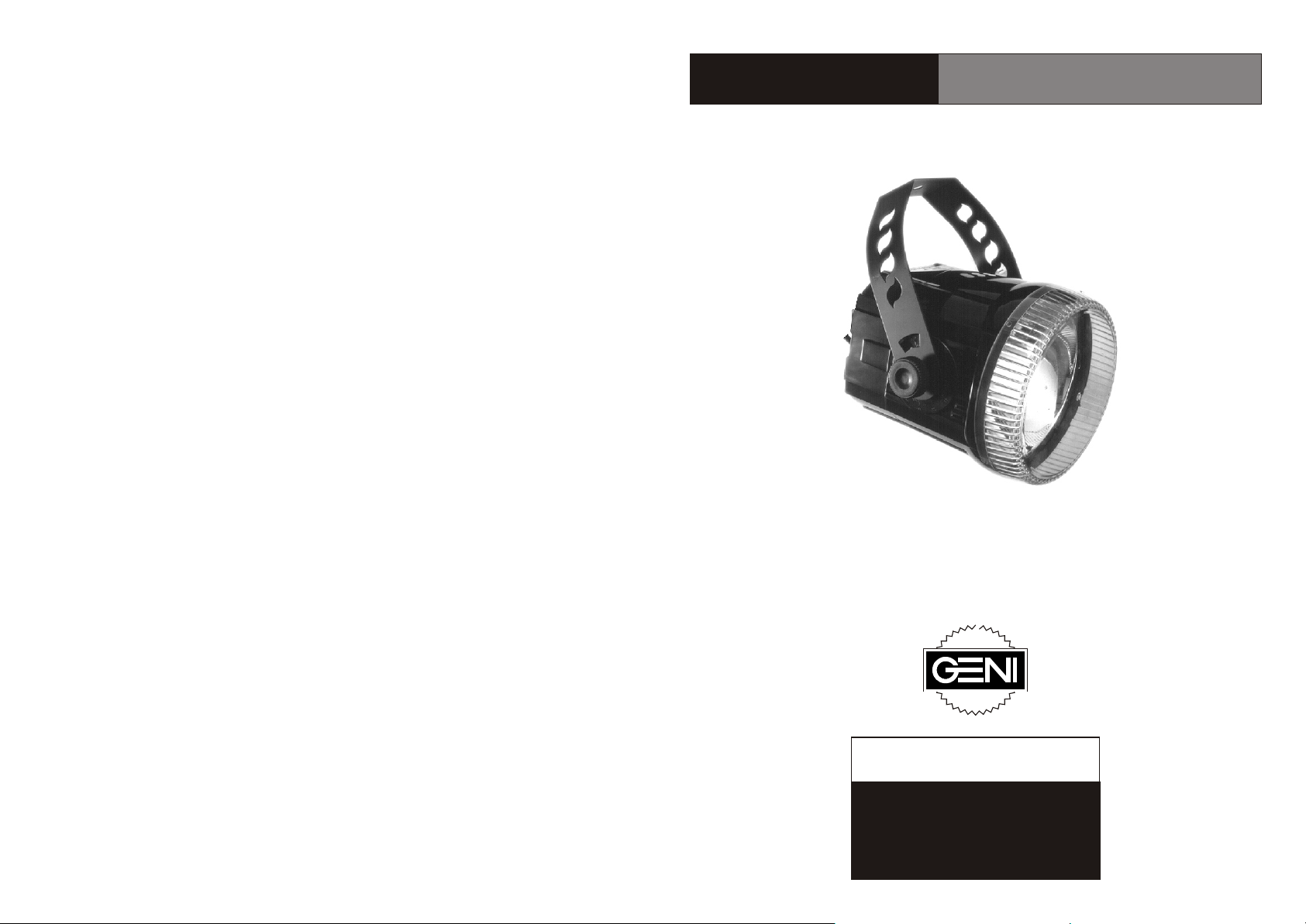
Zap Strobe
FL-45P, FL-75P, FL-150P
ã
Copyright 2002 Geni Electronics Co., Ltd.
Product specifications may be subject to change.
Please visit http://www.geni.com.tw for updates.
Have a Blast with Zap
The Powerfully Stylish Strobe
CAUTION!
Risk of electric shock
Read instructions before installing
or connecting to power
Page 2

Congratulations!
Thank you for buying a Geni product, and congratulations! You have one of
the best, most innovative strobe lights around.
With the Geni mark, you are ensured of high quality and reliability for years
to come. You can rely on Geni Electronics Co., Ltd., for more excellent
lighting products. We design and manufacture strobes, effects, and scanners.
And we create new items every day.
To keep abreast of it all, visit our web site: www.geni.com.tw. Or ask your
Geni dealer. We work closely to keep you -- our customer -- satisfied.
You can get some of the best quality, best priced products on the market
from Geni. So next time, look for Geni products, and get some of the
best entertainment lighting products around -- again!
Main Office/Factory:
Geni Electronics Co., Ltd.
No. 12, Alley 12, Lane 732
Chung Cheng Road, Yung Kang
Tainan Hsien, Taiwan
Tel: 886-6-253-8513
Fax: 886-6-253-8685
Showroom:
Geni Electronics Co., Ltd.
Taipei World Trade Center, Room 3A-04
No. 5, Section 5, Hsin Yi Road,
Taipei, Taiwan
Tel: 886-2-2722-2910
Fax: 886-2-2722-2918
Thank you!
1
Page 3

Maintenance
Always disconnect power and wait five minutes before servicing. Wipe strobe body
clean with a damp towel. Use a mild glass cleaner and towel to clean the lens and
interior reflector as needed. Do not dampen electronic parts, lamp or surrounding
material. Do not use powerful solvents to clean the lens or body: discoloration or
distortion may result.
Product Specifications
Dimensions: 200mm diameter x 230mm length (not including bracket)
Flash rate: Approximately 1 to 12 flashes per second (1-12 Hz)
Remote trigger signal: 10V DC positive pulse
Signal jack: 1/4inch (6.35mm) mono microphone jack
FL-45P, FL-75P, FL-150P Fuse: TIA/20mm VDE
Voltages available from manufacturer: 120V~60Hz; 230V~50Hz
Note: The 230V~50Hz model can be used in 240V~50Hz environments.
Name: Zap Strobe FL-45P
TM
Lamp: Geni ST-045 high output helical xenon strobe tube
Weight: 1.25kgs (120V); 1.29kgs (230V); 1.36kgs (230V CE)
Name: Zap Strobe FL-75P
TM
Lamp: Geni ST-075 high output helical xenon strobe tube
Weight: 1.29kgs (120V); 1.33kgs (230V); 1.40kgs (230V CE)
Warning!
Follow standard precautions for all electronic products.
Ÿ Disconnect from power source at least five minutes before removing
lens cover or servicing. Electric charge remains briefly after unit is
disconnected from electric power supply. Keep lens cover closed while
operating.
TM
Ÿ Zap Strobes contain no user serviceable parts. Servicing must be
conducted by qualified technicians only.
Ÿ Keep away from fire. Keep flammable material away from unit. Do not
operate in wet conditions or near liquids.
Ÿ Keep air vents clear to avoid overheating. Never insert objects into air
vents.
Ÿ Strobe lamps emit bright light. Do not look directly at lamp when lit.
Ÿ Disconnect mains power supply immediately if strobe falls or is struck.
Have a qualified technician inspect for safety before operating.
Ÿ Never remove warning or informative labels from the unit.
About Zap Strobes
TM
ZAP Strobes deliver a powerful flash -- with either manual or remote control. Their
stylish, lightweight case is ideal for mobile light shows or installations. Zap Strobes
come ready for use.
TM
TM
Name: Zap Strobe FL-150P
TM
Lamp: Geni ST-150 high output helical xenon strobe tube
TM
Zap Strobe models FL-45P, FL-75P and FL-150P are very similar in construction:
Their main difference is varying lamp wattage.
Weight:1.33kgs (120V); 1.40kgs (230V); 1.47kgs (230V CE)
1. Unpack your Zap Strobe. Zap Strobes come with lamp and bracket (A2)
TM TM
installed.
2. Geni products are inspected at the factory and shipped in perfect condition. If
damage occurred in transport, please contact your Geni dealer immediately.
3. Use a 5-kg rated C-clamp to secure the strobe bracket (A2) to trussing. Allow one
meter (three feet) of space for cooling. After adjusting strobe angle, tighten the
bracket knob (A7). Strobe can be operated at any angle. The angle guide (A8),
showing degrees of slant, is there for reference.
5 2
Page 4

TM
Zap Strobe, Illustration A
Back Panel, Illustration B
A1 - Hole for C-clamp
A2 - Bracket
A3 - Clasp
A4 - Lens
A5 - Strobe Body
A6 - Back Panel
(Details on Page 4)
A7 - Bracket Knob
A8 - Angle Guide
A6
A3
A5
A1
A2
A4
A7
A8
B1 - Product Specification Area
B2 - Certification Mark Area
B3 - Serial Number Area
B4 - Speed Adjustment Knob
B5 - Signal IN Connection
B6 - Signal OUT Connection
B7 - Mains Power Line
Note: Look at the Product
Specification Area to see
which strobe version you have
B4
B1
B5
B7
B2
B3
B6
and to know which instructions you
should follow.
Manual Control Operation
1. Make sure that power supply and product voltages are the same. Plug the Zap
Strobe mains power cord into properly grounded socket.
2. Twist the SPEED knob(B4) on the back of the unit to set flash rate. Zap Strobes
TM
TM
flash approximately from 1 to 12 times per second.
Lamp Replacement
Strobe lamps in FL-45P, FL-75P and FL-150P have a life of at least 5 million flashes.
Replace burnt-out strobe lamps in FL-45P, FL-75P and FL-150P as follows. Always
use appropriate Geni ST-series replacement lamps.
1. Disconnect power source. Let unit cool five minutes.
2. Use a Phillips-head screwdriver to remove the screw in the clasp that connects
Remote Control Operation
1. Link the strobe to an analog strobe controller, for example, Geni FL-01C or FL34C, as follows:
A. Plug one end of a standard microphone cable with 1/4-inch mono jacks to
the controller output socket.
B. Run your line to the first strobe. Insert the 1/4-inch mono jack into the Zap
TM
Strobe's IN (B5) socket. Insert another cable with 1/4-inch mono jacks into the first
strobe unit's OUT (B6) socket.
C. Run your line to the next strobe, and make connections by repeating the
process above. Observe controller instructions regarding the maximum number of
strobes that can be linked.
2. Make sure that power supply and product voltages are the same. Plug the Zap
TM
the lens (A4) to the strobe body (A5). While grasping the strobe body (A5), turn the
lens (A4) clockwise. You will hear a click. Remove the lens.
3. Grasp the burnt-out strobe lamp. Pull straight out. Discard old lamp properly.
Keep away from children and animals.
4. Cover your hands with lint-free gloves or cloth. Grasp the new strobe lamp tube.
Insert its pins straight into the strobe lamp socket. Do not touch lamp tube with bare
hands, as this will shorten the lamp life. Use rubbing alcohol and a lint-free cloth to
wipe lamp tube clean if it is accidentally touched.
5. Align the lens and body: A knob in the lens fits nicely into a slot in the body. Turn
the lens counterclockwise on the body, bringing the screw hole on the clasp (A3)
into place. Tighten the retaining screw into place.
Strobe mains power cord into properly grounded power source. Plug controller into
power source.
3. Adjust strobe flash rate according to your controller instructions. On the Geni FL01C controller, for example, simply turn on the POWER switch and twist the control
knob to adjust flash rate.
3 4
 Loading...