

Page 1
ISO 9001 CERTIFIED
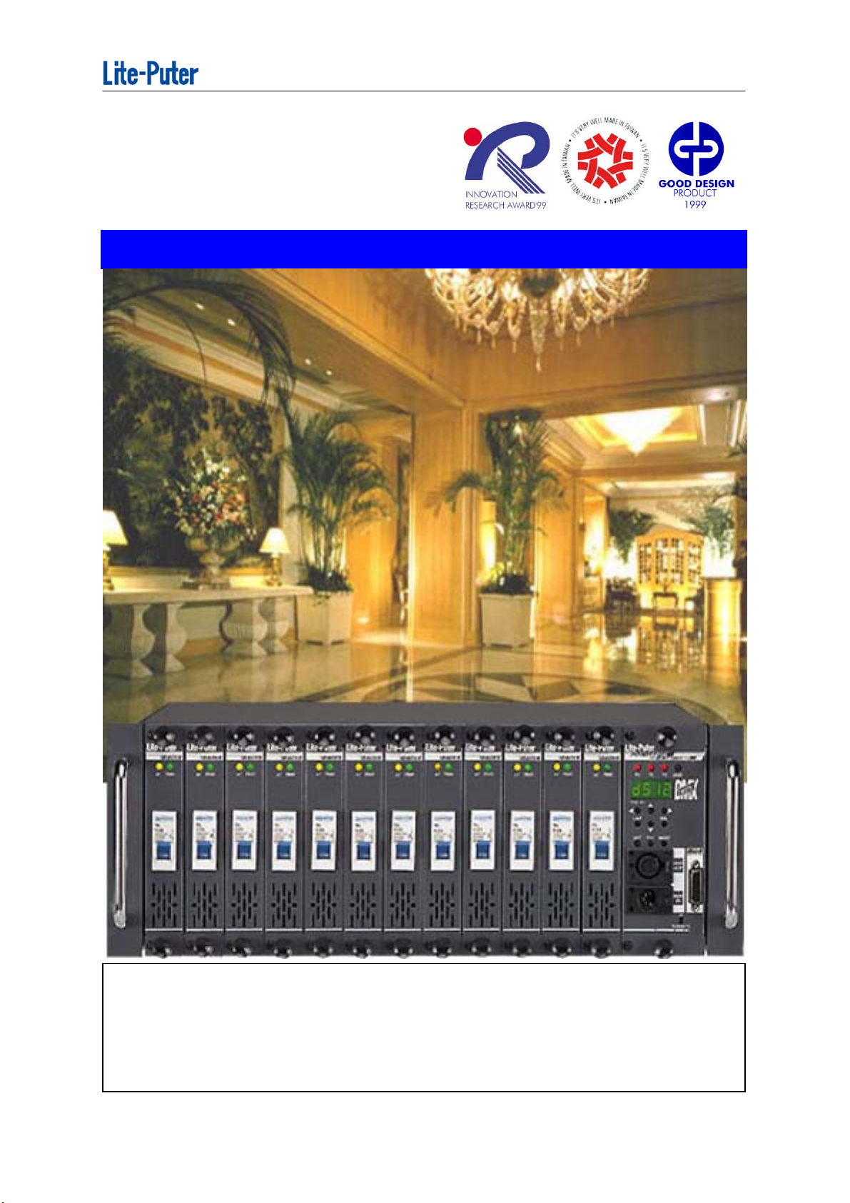
DX-1220
DMX 12CH. Modular Dimmer Pack
Lite-Puter Enterprise Co., Ltd.
Website: www.liteputer.com.tw
E-mail: litecom@ms2.hinet.net
Page 2
INDEX
ISO 9001 CERTIFIED
The regulation of safe usage
.......................................................................................................................................................2
Chapter 1. Introduction
1-1 Features of DX-1220..........................................................................................................3
1-2 Structure ............................................................................................................................4
1-3 Specification ......................................................................................................................4
Chapter 2. Installation and function introduction
2-1 Installation .........................................................................................................................5
2-2 The main function of P-27 ..............................................................................................5
2-3 Introduction of DP-5 ........................................................................................................6
2-4 Connection of DMX & ANALOG .....................................................................................7
2-5 Real panel ..........................................................................................................................7
Chapter 3. MODE
3-1 DMX mode............................................................................................................................8
3-2 ANALOG mode ....................................................................................................................8
3-3 OFF mode ...........................................................................................................................8
3-4 How to set the start address of channels.........................................................................9
3-5 How to connect with over 2 sets of DX-1220 ...............................................................10
Chapter 4. FUN (FUNCTION)
4-1 Display dimming level of each channel ..........................................................................11
4-2 Dimming level testing for each channel or all channel ...............................................12
4-3 Fade in and Fade out automatically testing for each channel or all channels .........12
4-4 Display the Voltage ...........................................................................................................13
4-5 Display internal temperature............................................................................................13
Chapter 5. SET
5-1 Set dimmer-warm up 0% --- 6% .......................................................................................14
5-2 Set dimming or switch for each channel or all channels. ............................................15
5-3 6 memory scenes --- be use for architectural lighting with CP-2A ............................16
5-4 Set fader time ...................................................................................................................17
5-5 The corresponding list of setting fader time..................................................................18
5-6 Set "square" or " 3 linear" dimming curve .....................................................................19
5-7 Maximum wattage limit setting........................................................................................20
Chapter 6. Specification of plug & wiring diagram
............................................................................................................................................... 21-22
Lite-Puter 1
Page 3
ISO 9001 CERTIFIED
The regulation of safe usage:
Setting for dimmer or switch on / off:
Individual channel must be set dimming or switching function before the
load switch ( circuit breaker) turns on.
The non-dimming lamp may be damaged in dimming function. Please refer
section 5-2.
The regulation of load.
To ensure the using time of DX-1220, we suggest you to refer to below
statements about the loading volume.
DX-1220 is normally settled in a rack, so the rack must be airy. If not, the inner
will be overheat and then DX-1220 will shut down or can't operate correctly.
Maximum output of individual channel is 25A
For the moments testing. ( about 10 minutes.)
Output of individual channel ≦20A :
For many hours . ( It's used for a theater or a stage. )
Output of individual channel ≦12A :
Continue working for the whole years. (It's used for hotels or
restaurants. )
Usage Environment
1. Indoor temperature : uder 35°c
2. The inner temperature of rack should not be over 45°c
3. Humidity:40% --- 80%
Dimming lamp cotrolled by DX-1220:
Incandescent lamp, Tungsten-halogen lamp, low-voltage halogen lamp with
tranformer.
Non-dimming lamp cotrolled by DX-1220:
Fluorescent lamp, High-pressure mercury lamp, Metal halide lamp,
High-pressure/ low-pressure sodium lamp.
Remark:
Lite-Puter offer DX-F02 dimming module for flourecent lamp for dimming.
Lite-Puter 2
Page 4
ISO 9001 CERTIFIED
Chapter 1. Introduction
DX-1220, a digital DMX 12 channels modular power pack. This new
sophisticated power pack is ideal and reliable for stage lighting, disco lighting,
as well as architectural lighting.
The Lite-Puter's DX-1220 is just not another ordinary power pack, but has the
versatility to meet your needs plus more. The smoothest lighting effects in its
class as well as it's quick maintenance makes the DX-1220 an ideal power
pack.
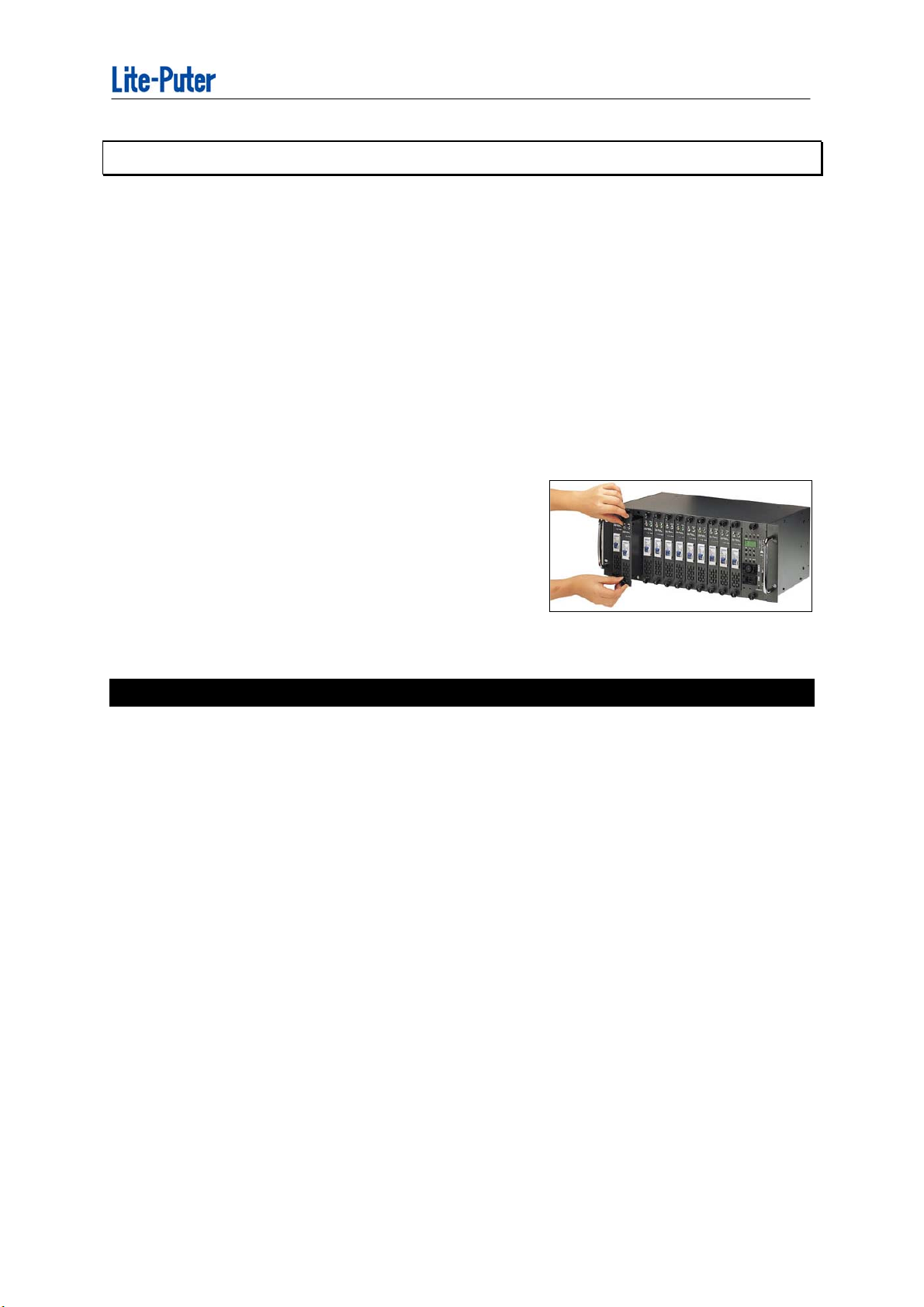
You will be pleased with not only the ability to
change a module without turning off all power,
but also the ability to remove any amount of
modules without removing the whole unit. The
DX-1220 has a variety of functions and testing
keys to help the user get maximum usage.
1-1 Features
It's suitable for theaters, stages, and architectural lighting system.
It can be accepted either DMX-512 signal or Analog 0-10V DC signal.
Auto Frequency tracking: 45 --- 63Hz can be adjusted automatically.
Digital dimming: Each channel can be set in dimming or in switch.
Square law and Linear dimming curve can be chosen.
Dimming test for each channel or all channles.
100-120 VAC / 200-240 VAC can be changed automatically.
Maxiumum waltage limit setting.
LED displays DMX address and voltage, dimming level and temperature.
Each or all channels can be set warm-up 0---6.0% to protecting lamps.
6 scenes memorized.
( It's used for architectural lighting system with CP-2A.)
Lite-Puter 3
Page 5
ISO 9001 CERTIFIED
1-2 Structure
Modular design:
It is easy to replace, repair and change each independent module and update
software in DP-5 CPU interface.
25A magnetic circuit breaker on each P-27.
Four temperature-controlled fans.
When the internal temperature is over 37℃, the fans start to work 1 minute and
stop 1 minute in turn;
over to 41℃, the fans turn continuously;
over 75℃, all output will be stopped until the temperature goes down 70℃.
SSR :40A/600V (75℃) Itrms=40A
Itsm=350A / 60HZ , 300A / 50HZ (25℃)
According with UL 81734
1-3 Speciafication
■ AC INPUT:100V-120V / 200V-240V, 45-63HZ
3 phases 4 wires or single phase 3 wires.
■ LOAD: 20A MAX output per channel
■ DMX signal ( 5 pin XLR): DMX512 / 1990
■ DMX signal input channel:512 channels
■ DMX signal input connector:XLR 5-pin
■ Analog signal input valtage: 0-10V DC
■ Analog signal input channel (D TYPE 15pin):12 channels
■ Analog signal connector:D TYPE connector 15 PIN
■ Dimension: 19” 4U:482(L) x 176(H) x 260(D)mm
■ Weight: 20.5 KG
Lite-Puter 4
Page 6
ISO 9001 CERTIFIED
Chapter 2. Installation and function introduction
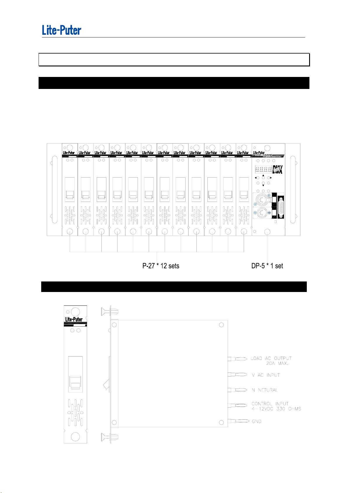
2-1 Installation
DX-1220 is composed of 12 sets "P-27" ( one channel module ) and 1 set of
"DP-5" ( DMX interface ). The modular design is for easy to replace, repair
and change update software fast.
P-27 PACK P-27 PACK
AC TRIG
AC TRIG
P-27 PACK
AC TRIG
P-27 PACK
AC TRIG
P-27 PACK
AC TRIG
P-27 PACK
AC TRIG
2-2 The main function of P-27
P-27 PACK
AC TRIG
P-27 PACK
AC TRIG
P-27 PACK
AC TRIG
P-27 PACK
AC TRIG
P-27 PACK
AC TRIG
P-27 PACK
AC TRIG
V1 V2 V3 DMX
FIRST CH.
CAN
SEL
SET
FNC
MODE
Front panel
0-10VDC
ANALOGIN
PUSH
DMX
OUT
DMX
IN
ON
TERMINATE
P-27 PACK
TRIGAC
P-27 (One Channel Driver Module)
Lite-Puter 5
Page 7
ISO 9001 CERTIFIED
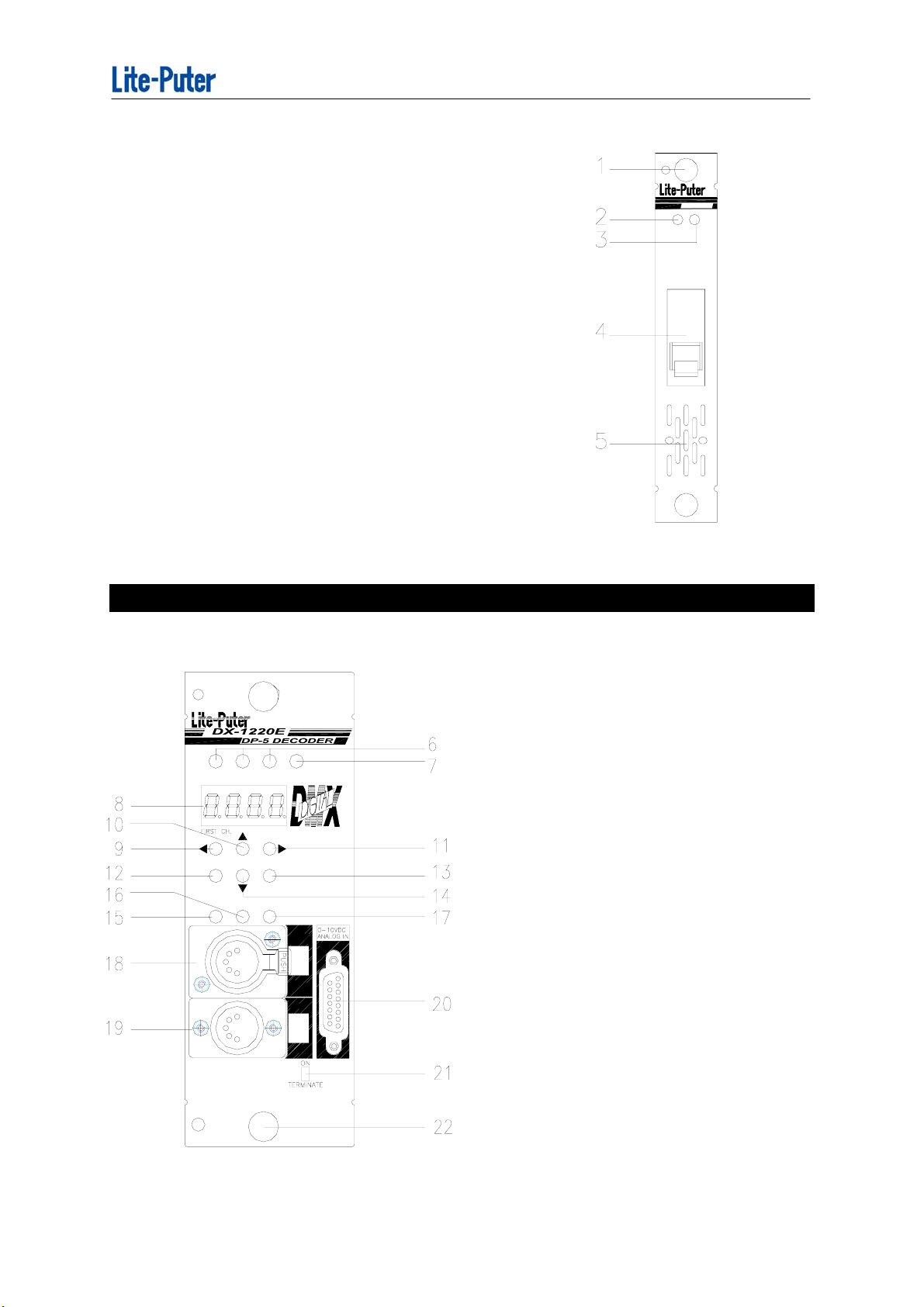
P-27
Unlock / lock knob: pull-unlock, push-lock.
1.
2.
AC output indicator
3.
Trig indicator.
4.
25A magnetic circuit breaker
Ventilator
5.
Specifications:
AC input : 100 --- 240VAC
AC output : 20A MAX
Control input : 4 --- 12VDC
Dimension : 30 * 176 * 192 mm ( W * H * D )
Weight : 0.92 Kg
P-27 PACK
TRIGAC
2-3 Introduction of DP-5
V3V2V1 DMX
CAN
SEL
FNCSET
MODE
DMX
OUT
( 6) Phase input indicators
( 7) DMX signal input indicator
( 8) LED display
( 9) wbutton
(10) 5button
(11) 4button
(12) CANCEL button
(13) SEL / select button
(14) 6button
(15) SET/ setting button
(16) FUN / function button
(17) MODE button
DMX
IN
(18) 5 PIN DMX "OUT" connector
(19) 5 PIN DMX "IN" connector
(20) 0-10VDC connector
(21) Terminate switch
(22) Unlock / lock knob: pull-unlock
push-lock
Puter 6
Lite-
Page 8

ISO 9001 CERTIFIED
2- 4 Connection of DMX & ANALOG
The DP-5 is photo isolated from DMX signal input; data transfer is done by
photo coupler.
CAUTION:
For using 5 pin XLR plug, do not connect PIN 1 to the housing of the plug.
DMX Connection
XLR 5pin
PIN 1: GND
PIN 2: DATA PIN 3: DATA +
PIN 4: NC
PIN 5: NC
Analog Connector
Analog Connection
D-type 15pin
PIN 1: CH-1
PIN 2: CH-2
PIN 3: CH-3
-
PIN 12: CH-12
PIN 13: NC
PIN 14: DC OUTPUT
+12V / 100mA
PIN 15: GND
2-5 REAL PANEL
FOR 3 PHASE 4 WIRES
E GND
N
V1 V1(100A max)
V2
V2'
V3 V3(100A max)
EE
N
V1 V1
V2
V2'
V3 V3
FOR 1 PHASE 3 WIRES
E GND
N
N N
V1 V(100A max)
V2
V2(100A max)
V2'
V'(100A max)
V3
23
N
V2
V2'
12N
LOAD
E
CH12 CH11
LOAD
11NE
EN10 N N98 7EN E6NN
LOAD
E
CH10 CH8CH9
LOADLOAD
E
CH7 CH6
LOADLOAD
24
(23) AC Main power input terminal 3 phases 4wires.
(Max. 150A for each connecting point)
N4N53EN NE21
LOAD
E
CH5
CH4 CH3
LOADLOAD
E
LOAD LOAD
E
CH2 CH1
25
(24) Temperature controlled fans.
(25) Load output terminal (Max. 30A for each connecting point)
Lite-Puter 7
Page 9

ISO 9001 CERTIFIED
Chapter 3. MODE
Press "MODE" key ,DX-1220 will offer 3 operation modes:
"DMX" , "ANALOG" and "OFF" mode.
3-1 DMX mode
In the DMX mode, DX-1220 will accept DMX-512 dimming signal input also analog 0 --10VDC signal.
Press "MODE" key to choose DMX mode, the LED will display the selected address
of DMX as follows,and then press "SEL" key to confirm.
3-2 ANALOG mode
In the ANALOG mode, DX-1220 will only accept ANALOG signal input.
Press "MODE" key to choose ANALOG mode, the LED will display as follows, and
then press "SEL" to confirm.
3-3 OFF mode
In the OFF mode, DX-1220 will not accept any signal.
Press "MODE" key to choose OFF mode, the LED will be display as follows, and
then press "SEL" to confirm.
When system is turned on, memory resets to last selected mode prior
to turning off. For example, if "OFF" mode was selected, then "OFF" mode
continues when system is turned on.
Lite-Puter 8
Page 10

ISO 9001 CERTIFIED
3-4 How to set the start address of channels
Operation:
Press "MODE" key to choice DMX mode, and then press the assist key to confirm
the correct start address of DMX channels.
Assist key:
Press【 4】: Increase channel
eg: Led display from d 0 0 1 to d 0 0 2.
Press【 w】: Decrease channel
eg: Led display from d 0 0 2 to d 0 0 1.
Press【 5】
Press【 6】
: I
ncrease 12 channels.
eg: Led display from d 0 0 1 to d 0 1 3.
:
Restore back to d 0 0 1.
Press【SEL】: Select / Confirmation key.
PS: (1) In the DMX mode, total 512 channels can be set start address by
users. (Each DX-1220 has 12 channels output.)
Eg.: If start address is set d 0 0 1 by users, and DX-1220 has
DMX 1st channel ------ 12th channel .
Eg.: If start address is set d 0 1 3 by users, and DX-1220 has
DMX 13th channel ------ 24th channel .
(2) DX-1220 can be set same address over 2 sets of DX-1220.
Lite-Puter 9
Page 11

ISO 9001 CERTIFIED
3-5 How to connect with over 2 sets of DX-1220
Only the last one of DX-1220
Terminate switch ---- ON
IN
OUT
IN
OUT
IMPORTANT
When a system is composed of
several DX-1220, only the
terminate switch of the last
DX-1220 stays "on" to keep fine
communication, and the others
stay "off".
IN
OUT
IN
DMX CONSOLE
Lite-Puter 10
Page 12

ISO 9001 CERTIFIED
Chapter 4. FUN (FUNCTION)
Press "FUN" key in turn and the LED will display 5 functions as
follows:
(1) Displays dimming level of each channel.
(2) Set dimming level testing for each channel or all channels.
(3) Fade in and fade out automatical testing for each channel or all channels.
(4) Display the AC voltage .
(5) Display internal temperature.
4-1 Display dimming level of each channel
Auto scan to the dimming level of each
channel.
Channel
number
Auto scan or by manual is optional.
Indicator Key: By manual
Press【4】: Increase 1 channel.
Press【w】: Decrease 1 channel.
Dimming Level is
00 -- FL(100%)
Eg.: Led display from 0 1.0.0 to 0 2.0.0
Eg.: Led display from 0 2.0.0 to 0 1.0.0
Lite-Puter 11
Page 13

ISO 9001 CERTIFIED
4-2
Test all
channels
Dimming level testing for each channel or all channels.
Please turn off DMX signal input (come from
the Console ) before executing this function.
This function can change dimming level of
each channel or all channles to test
Dimming level
output
Indicator key
Press【 4】: test one channel --Increase 1 channel
eg: Led displays from 0 1. 0 0 to 0 2. 0 0.
Press【 w】: test one channel -- decrease 1 channel
eg: Led displays from 0 2.0 0 to 0 1. 0 0 .
Press【 5】
Press【 6】
Press【CAN】: Function over and restore to last confirmed mode.
: I
ncrease dimming level.
eg: Led displays from 0 8.0 0 to 0 8. F L .
:
Decrease dimming level.
eg: Led displays from 0 8.F L to 0 8. 0 0 .
1. The dimming level of channles can be saved SC=1 --- SC=6, and recalled
by CP-2 control panel. Please refer to section 5-3.
2. When a channel is set as non-dimming function, DX-1220 will be started
and turn full on when the dimming level is over 51%.
4-3 Fade in and Fade out automatical testing for each channel or
all channles
Please turn off DMX signal input before
executing this function.
Automatic
Fade in and
Fade out
All channles
Lite-Puter 12
Page 14

ISO 9001 CERTIFIED
Indicator key :
Press【 4】: auto fade one channel ---- Increase channel.
Press【 w】: auto fade one channel ---- decrease channel.
Press【SEL】
Press【CAN】: Function over and restore to last confirmed mode.
When a channel is set as non-dimming function, it will light when the percent
of this channel light over
4-4 Display the Voltage
: To confirm
51%.
.
(Only display the Voltage of V3)
Displays the current AC voltage and will
change to 200 - 240VAC automatically if the
AC input is 230VAC.
4-5 Display internal temperature
Internal temperature displayed to prevent
from overheat and to control the operation
of fans.
(1) To avoid inhaling dust. the fans controlled by temperature.
When the internal temperature is over 37℃, the fans start to work 1
minute and stop 1 minute in turn.
(2) When the internal temperature is over 41℃, the fans turn continuously .
(3) When the internal temperature is over 75℃, all output will be stopped until
the temperature goes down 70℃. In this case, please check if the load
are verload and the dimmer rack is stuffy.
Please refer to the regulations of safe usage in page 2.
Lite-Puter 13
Page 15

ISO 9001 CERTIFIED
Chapter 5. SET
Press "SET" key in turn and the LED will display 6 functions as follows:
(1) Set dimmer warm-up 0%---6.0%.
(each channel or all channels.)
(2) Set dimming or switching (non dim) for
each channel or all channels.
(3) 6 memory scenes. (must be connected with CP-2A)
(4) Set fader time: 0.1 SEC.----30 MIN.
(5) Set Square Law or Linear dimming curve.
(6) Maximum waltage limit setting.
5-1 Set dimmer- warm up 0 %--- 6.0 %
All channles
Indicator key :
Press【 4】: Increase channels.
Press【 w】: Decrease channels.
Press【 5】
Press【 6】
Press【CAN】: Function over and restore to last confirmed mode.
: I
ncrease dimmer- warm up value.
:
Decrease dimmer- warm up value..
Dimmer-warm up value 0 ~ 6.0%
1. Warm up fuction will not available, If any channel is setted to switching.
(Non dim)
2. Please note : the original pre-heating value is set to 100%.
Lite-Puter 14
Page 16

ISO 9001 CERTIFIED
5-2 Set dimming or switching for each channel or all channels.
Dimming / Non-dimming setting:
Before operating the dimmer, please check the features of your loads if they can dim
or not, for those lamps which can not dim such as flourescent lamp, high-pressure
mercury lamp, high pressure / low pressure sodium lamp or some fixtures with
motors; please set the channel as non-dim. Non-dim loads may be destroyed if they
are set as dimmable.
When a channel is set as non-dimming function, the light will be 100% bright,
When the input is over 50% and it will be switched off when the input is under 25%.
This delay function is to prevent the twinkling situation.
When a channel is set as non-dimming function, this channel doesn't have the
pre-heat and output waltage llimit setting function.
d=Dimming
All channles are set with dimming.
S=Swithing
All channles are set with switching.
Dimming and Switching mixed.
All channles can be set dimming or switching.
Indicator key set each channel:
Press【 4】: Increase channel.
Press【 w】: Decrease channel.
Press【 5】
Press【 6】
:
Switching (non dim).
:
Dimming..
Press【SEL】: Select / Confirmation key.
Lite-Puter 15
Page 17

ISO 9001 CERTIFIED
Please note:the original setting of all channels is dimming function.
5-3 6 memory scenes --
Indicator key :
Press【 4】: SC=1 SC=2 SC=3 SC=4 SC=5 SC=6
Press【 w】: SC=6 SC=5 SC=4 SC=3 SC=2 SC=1
First input the dimming signal to DX-1220 by linking to an external dimming console
(DMX / Analog) or a self-test function, then choose SC=0 or SC=1 --- SC=6
Press【SEL】: Select / Confirmation key.
1. SC=0 will execute automatically when DX-1220 power is switched on.
be use for architectural lighting with CP-2A
DX-1220 can be set 6 memory scenes to
control architectural lighting by
connecting with CP-2A . (Architectural
lighting control panelof Lite-Puter)
2. SC=1 --- SC=6 have to be executed by an external CP-2A.
3. The fade-in / fade-out time can be set by section 5-4.
Lite-Puter 16
Page 18

ISO 9001 CERTIFIED
5-4 Set fader time (be
Set fader time
( Please refer to section 5-5.)
≡: All channels
1 : 1st channel
2 : 2th channel
3 : 3th channel
4 : 4th channel
5 : 5th channel
6 : 6th channel
7 : 7th channel
8 : 8th channel
9 : 9th channel
A : 10th channel
B : 11th channel
C : 12th channel
Use for architectural lighting )
Indicator key :
Press【 4】: Increase channels.
Press【 w】: Decrease channels.
Press【 5】
Press【 6】
Press【SEL】: Select / Confirmation key.
: Extend time
: Sorten time
.
..
Lite-Puter 17
Page 19

ISO 9001 CERTIFIED
5-5 The corresponding list of setting fader time(from 00 --- to FL)
set 50Hz 60Hz set 50Hz 60Hz set 50Hz 60Hz set 50Hz 60Hz set 50Hz 60Hz set 50Hz 60Hz set 50Hz 60Hz set 50Hz 60Hz
00
NoFade NoFade
01 00'03 00'02 21 01'24 01'10 41 02'46 02'18 61 04'07 03'26 81 05'49 04'51 A1 12'37 10'31 C1 19'25 16'11 E1 26'13 21'51
02 00'05 00'04 22 01'27 01'12 42 02'48 02'20 62 04'10 03'28 82 06'02 05'02 A2 12'50 10'42 C2 19'38 16'22 E2 26'26 22'02
03 00'08 00'06 23 01'29 01'14 43 02'51 02'22 63 04'12 03'30 83 06'15 05'12 A3 13'03 10'52 C3 19'51 16'32 E3 26'39 22'12
04 00'10 00'09 24 01'32 01'17 44 02'53 02'25 64 04'15 03'33 84 06'28 05'23 A4 13'16 11'03 C4 20'04 16'43 E4 26'52 22'23
05 00'13 00'11 25 01'34 01'19 45 02'56 02'27 65 04'18 03'35 85 06'40 05'34 A5 13'28 11'14 C5 20'16 16'54 E5 27'04 22'34
06 00'15 00'13 26 01'37 01'21 46 02'59 02'29 66 04'20 03'37 86 06'53 05'44 A6 13'41 11'24 C6 20'29 17'04 E6 27'17 22'44
07 00'18 00'15 27 01'39 01'23 47 03'01 02'31 67 04'23 03'39 87 07'06 05'55 A7 13'54 11'35 C7 20'42 17'15 E7 27'30 22'55
08 00'20 00'17 28 01'42 01'25 48 03'04 02'33 68 04'25 03'41 88 07'19 06'06 A8 14'07 11'46 C8 20'55 17'26 E8 27'43 23'06
09 00'23 00'19 29 01'45 01'27 49 03'06 02'35 69 04'28 03'43 89 07'31 06'16 A9 14'19 11'56 C9 21'07 17'36 E9 27'55 23'16
0A 00'26 00'21 2A 01'47 01'29 4A 03'09 02'37 6A 04'30 03'45 8A 07'44 06'27 AA 14'32 12'07 CA 21'20 17'47 EA 28'08 23'27
0B 00'28 00'23 2B 01'50 01'31 4B 03'11 02'39 6B 04'33 03'47 8B 07'57 06'37 AB 14'45 12'17 CB 21'33 17'57 EB 28'21 23'37
0C 00'31 00'26 2C 01'52 01'34 4C 03'14 02'42 6C 04'35 03'50 8C 08'10 06'48 AC 14'58 12'28 CC 21'46 18'08 EC 28'34 23'48
0D 00'33 00'28 2D 01'55 01'36 4D 03'16 02'44 6D 04'38 03'52 8D 08'22 06'59 AD 15'10 12'39 CD 21'58 18'19 ED 28'46 23'59
0E 00'36 00'30 2E 01'57 01'38 4E 03'19 02'46 6E 04'41 03'54 8E 08'35 07'09 AE 15'23 12'49 CE 22'11 18'29 EE 28'59 24'09
0F 00'38 00'32 2F 02'00 01'40 4F 03'21 02'48 6F 04'43 03'56 8F 08'48 07'20 AF 15'36 13'00 CF 22'24 18'40 EF 29'12 24'20
20 01'22 01'08 40 02'43 02'16 60 04'05 03'24 80 05'37 04'41 A0 12'25 10'21 C0 19'13 16'01 E0 26'01 21'41
10 00'41 00'34 30 02'02 01'42 50 03'24 02'50 70 04'46 03'58 90 09'01 07'31 B0 15'49 13'11 D0 22'37 18'51 F0 29'25 24'31
11 00'43 00'36 31 02'05 01'44 51 03'27 02'52 71 04'48 04'00 91 09'13 07'41 B1 16'01 13'21 D1 22'49 19'01 F1 29'37 24'41
12 00'46 00'38 32 02'08 01'46 52 03'29 02'54 72 04'51 04'02 92 09'26 07'52 B2 16'14 13'32 D2 23'02 19'12 F2 29'50 24'52
13 00'48 00'40 33 02'10 01'48 53 03'32 02'56 73 04'53 04'04 93 09'39 08'02 B3 16'27 13'42 D3 23'15 19'22 F3 30'03 25'02
14 00'51 00'43 34 02'13 01'51 54 03'34 02'59 74 04'56 04'07 94 09'52 08'13 B4 16'40 13'53 D4 23'28 19'33 F4 30'16 25'13
15 00'54 00'45 35 02'15 01'53 55 03'37 03'01 75 04'58 04'09 95 10'04 08'24 B5 16'52 14'04 D5 23'40 19'44 F5 30'28 25'24
16 00'56 00'47 36 02'18 01'55 56 03'39 03'03 76 05'01 04'11 96 10'17 08'34 B6 17'05 14'14 D6 23'53 19'54 F6 30'41 25'34
17 00'59 00'49 37 02'20 01'57 57 03'42 03'05 77 05'03 04'13 97 10'30 08'45 B7 17'18 14'25 D7 24'06 20'05 F7 30'54 25'45
18 01'01 00'51 38 02'23 01'59 58 03'44 03'07 78 05'06 04'15 98 10'43 08'56 B8 17'31 14'36 D8 24'19 20'16 F8 31'07 25'56
19 01'04 00'53 39 02'25 02'01 59 03'47 03'09 79 05'09 04'17 99 10'55 09'06 B9 17'43 14'46 D9 24'31 20'26 F9 31'19 26'06
1A 01'06 00'55 3A 02'28 02'03 5A 03'50 03'11 7A 05'11 04'19 9A 11'08 09'17 BA 17'56 14'57 DA 24'44 20'37 FA 31'32 26'17
1B 01'09 00'57 3B 02'30 02'05 5B 03'52 03'13 7B 05'14 04'21 9B 11'21 09'27 BB 18'09 15'07 DB 24'57 20'47 FB 31'45 26'27
1C 01'11 01'00 3C 02'33 02'08 5C 03'55 03'16 7C 05'16 04'24 9C 11'34 09'38 BC 18'22 15'18 DC 25'10 20'58 FC 31'58 26'38
1D 01'14 01'02 3D 02'36 02'10 5D 03'57 03'18 7D 05'19 04'26 9D 11'46 09'49 BD 18'34 15'29 DD 25'22 21'09 FD 32'10 26'49
1E 01'17 01'04 3E 02'38 02'12 5E 04'00 03'20 7E 05'21 04'28 9E 11'59 09'59 BE 18'47 15'39 DE 25'35 21'19 FE 32'23 26'59
F 01'19 01'06 3F 02'41 02'14 5F 04'02 03'22 7F 05'24 04'30 9F 12'12 10'10 BF 19'00 15'50 DF 25'48 21'30 FF 32'36 27'10
Lite-Puter 18
Page 20

ISO 9001 CERTIFIED
5-6 Set "square law " or " linear" dimming curve
Square law dimming curve:C2
It can react the linear relationship between dimming scale and output waltage, so it
would be easy to evaluate the precision of the output waltage.
Linear dimming curve:C3
This is suited for the stage lighting. The output voltage value and the controlling
value are in linear ratio, and it enables a wider control range in low brightness, so the
professional lighting designers prefer to this.
Indicator key :
Press【 5】
Press【 6】
Press【SEL】: Select / Confirmation key
:
Change dimming curve
:
Change dimming curve
NOTE:Original setting is C3.
The human eyes are most
100%
LIGHT OUTPUT
sensitive to the light brightness
range, which is under 25% of
the 100% brightness, so the use
of curve C3 enables a wider
control range.
C2
C3
DIMMER TRAVEL %
100%
Lite-Puter 19
Page 21

ISO 9001 CERTIFIED
5-7 Maximum Output Waltage Limit Setting :
Maximum waltage limit setting
From 50%---FF% (Full lighting)
≡: All channels
1 : 1st channel
2 : 2th channel
3 : 3th channel
4 : 4th channel
5 : 5th channel
6 : 6th channel
7 : 7th channel
8 : 8th channel
9 : 9th channel
A : 10th channel
B : 11th channel
C : 12th channel
Indicator key :
Press【 4】: Increase channels.
Press【 w】: Decrease channels.
Press【 5】
Press【 6】
Press【SEL】: Select / Confirmation key.
1. When a channel is set as non-dimming function, this channel doesn't have the
pre-heat and output waltage llimit setting function.
2. The original setting of all channels is FF ; means 100% output.
:
Increase percentage of waltage
:
Decrease percentage of waltage.
Lite-Puter 20
Page 22

ISO 9001 CERTIFIED
Chapter 6. Output Socket Panel (Option)
1 USA.
2 AUSTRALIA
3 FRANCE
4 ITALIAN
6CH.
6CH.
6CH.
6CH.
5 JAPANESE-C-TYPE
6CH.
6 JAPANESE-T-TYPE
6CH.
7 GERMANY
6CH.
8 GERMANY
6CH.
9 SOCAPEX 19 PIN
6CH. X 2
10 UK.
6CH.
Lite-Puter 21
Page 23

g
g
ISO 9001 CERTIFIED
22
Wirin
dia
ram of DX-1220
DX-1220V0 [EUM-C]
Lite-Puter
 Loading...