

Page 1
WWW.BEGLEC.COM
Operation Manual
Mode d'emploi
Gebruiksaanwijzing
Bedienungsanleitung
Manual de instrucciones
Manual do utilizador
EN
FR
NL
DU
ES
PT
Reproduction or publication of the content in any manner, without express permission of the publisher, is prohibited.
Copyright © 2007 by BEGLEC cva.
Version: 1.0
The Power Source for DJ’s
Page 2
EN - DISPOSAL OF THE DEVICE
Dispose of the unit and used batteries in an environment friendly manner
according to your country regulations.
FR - DÉCLASSER L’APPAREIL
Débarrassez-vous de l’appareil et des piles usagées de manière écologique
Conformément aux dispositions légales de votre pays.
NL - VERWIJDEREN VAN HET APPARAAT
Verwijder het toestel en de gebruikte batterijen op een milieuvriendelijke
manier conform de in uw land geldende voorschriften.
DU - ENTSORGUNG DES GERÄTS
Entsorgen Sie das Gerät und die Batterien auf umweltfreundliche Art und
Weise gemäß den Vorschriften Ihres Landes.
ES - DESHACERSE DEL APARATO
Reciclar el aparato y pilas usadas de forma ecologica conforme a las
disposiciones legales de su pais.
PT - COMO DESFAZER-SE DA UNIDADE
Tente reciclar a unidade e as pilhas usadas respeitando o ambiente e em
conformidade com as normas vigentes no seu país.
Page 3
ENGLISH OPERATION MANUAL
Thank you for buying this JBSystems®product. To take full advantage of all possibilities,please read these
operatinginstructionsverycarefully.
FEATURES
This unit is radio-interference suppressed. This appliance meets the requirements of the current European
and national guidelines. Conformity has been established and the relevant statements and documents have
been deposited by the manufacturer.
14 inputson6 channels (6line, 3phonos,3mics, 2USB)
2 BidirectionalUSB connections (play and record at the same time!)
1 separate balanced DJ mic with talkover
Gain, treble,mid, bass controls on all channels
Assignableand easy replaceablecrossfader
High quality,easy gliding “steel rail” DJ faders
2 Master outputs with individual balance controls
Master1with balanced XLRoutputs and signal trimming
LED VU-meters on input channels and master1
Veryaccurate automatic beat counters
Crossfaderstarts for compatible CD players
Pre-fadelistening with cue mixoption
BEFORE USE
Before you start using this unit, please check if there’s no transportation damage. Should there be any, do
not use the device and consultyour dealerfirst.
Important:
for the user to strictly followthe safetyinstructions and warnings in this user manual. Any damage caused
by mishandling is not subject to warranty. The dealer will not acceptresponsibility for any resulting defects
orproblems caused by disregarding this user manual.
Keep this booklet in a safe place for future consultation. If you sell the fixture, be sure to add this user
manual.
To protect theenvironment,please try to recyclethe packing material as much as possible.
Check the contents:
Check that the carton contains the followingitems:
Mixer
Mainscable
Operatinginstructions
This device left our factory in perfect condition and well packaged. It is absolutely necessary
SAFETY INSTRUCTIONS:
CAUTION
The lightning flash with arrowhead symbol within the equilateral triangle is intended to alert the use
or the presence of un-insulated “dangerous voltage” within the product’s enclosure that may be of
sufficient magnitude to constitute a risk of electricshock.
The exclamation point within the equilateral triangle is intended to alert the user to the presence of
important operation and maintenance (servicing) instructions in the literature accompanying this
appliance.
CAUTION: To reduce the risk of electric shock, do not remove the top
cover. No user-serviceable parts inside. Refer servicing to qualified
servicepersonnel only.
ENGLISH OPERATION MANUAL
To prevent fire or shock hazard, do not expose this appliance to rain or moisture.
To avoid condensation to be formed inside, allow the unit to adapt to the surrounding temperatures when
bringing it into a warm room after transport. Condense sometimes prevents the unit from working at full
performance or may even cause damages.
This unit is for indoor use only.
Don’t place metal objectsor spill liquid inside the unit. No objectsfilled with liquids, such as vases, shall be
placed on this appliance. Electric shock or malfunction may result. If a foreign object enters the unit,
immediately disconnectthe mains power.
No naked flame sources, such as lighted candles,should be placed on the appliance.
Don’t cover any ventilation openings as this may result in overheating.
Preventuse in dusty environmentsand clean the unit regularly.
Keep the unit away from children.
Inexperienced persons should not operatethis device.
Maximumsave ambienttemperature is 40°C. Don’t use this unit athigher ambient temperatures.
Minimumdistancesaround the apparatus for sufficient ventilation is 2cm.
Alwaysunplug the unit when it is not used for a longer time or before you start servicing.
The electricalinstallation should be carried out by qualified personal only, according to the regulations for
electricaland mechanical safety in your country.
Check that the available voltage is not higher than the one stated on the rear panel of the unit.
The socket inlet shall remain operablefordisconnection from the mains.
The powercord should always be in perfectcondition. Switch the unit immediatelyoff when the power cord
is squashed or damaged. It must be replaced by the manufacturer, its service agent or similarly qualified
persons in order to avoid a hazard.
Never let the power-cord come into contact with other cables!
When the powerswitch is in OFF position, this unit is not completely disconnected from the mains!
In order to prevent electric shock, do not open the cover. Apart from the mains fuse there are no user
serviceablepartsinside.
Never
repair a fuse or bypass the fuse holder.
type and electrical specifications!
In the event of serious operating problems, stop using the appliance and contactyourdealer immediately.
Pleaseuse the original packing when the device is to be transported.
Due to safety reasonsit is prohibited to make unauthorized modifications to the unit.
INSTALLATION GUIDELINES:
Installthe unit in a well-ventilated location where it will not be exposedto high temperatures or humidity.
Placing and using the unit for long periods near heat-generating sources such as amplifiers,spotlights, etc.
will affect its performance and may even damage the unit.
The unit can be mounted in 19-inch racks. Attach the unit using the 4 screw holes on the front panel. Be
sure to use screws of the appropriate size. (screws not provided) Take care to minimize shocks and
vibrationsduring transport.
When installed in a booth or flight case, please make sure to have good ventilation to improve heat
evacuationof the unit.
To avoid condensation to be formed inside, allow the unit to adapt to the surrounding temperatures when
bringing it into a warm room after transport. Condense sometimes prevents the unit from working at full
performance.
CLEANING THE MIXER:
Clean by wiping with a polished cloth slightly dipped with water. Avoid getting water inside the unit. Do not
use volatile liquids such as benzene or thinner which will damage the unit.
Always
replace a damaged fuse with a fuse of the same
This symbolmeans:indoor useonly.
This symbol means:Read instructions.
This symbol means: Safety Class II appliance
JB SYSTEMS 1/44 BEAT6 USB
JB SYSTEMS 2/44 BEAT6 USB
Page 4
ENGLISH OPERATION MANUAL
ENGLISH OPERATION MANUAL
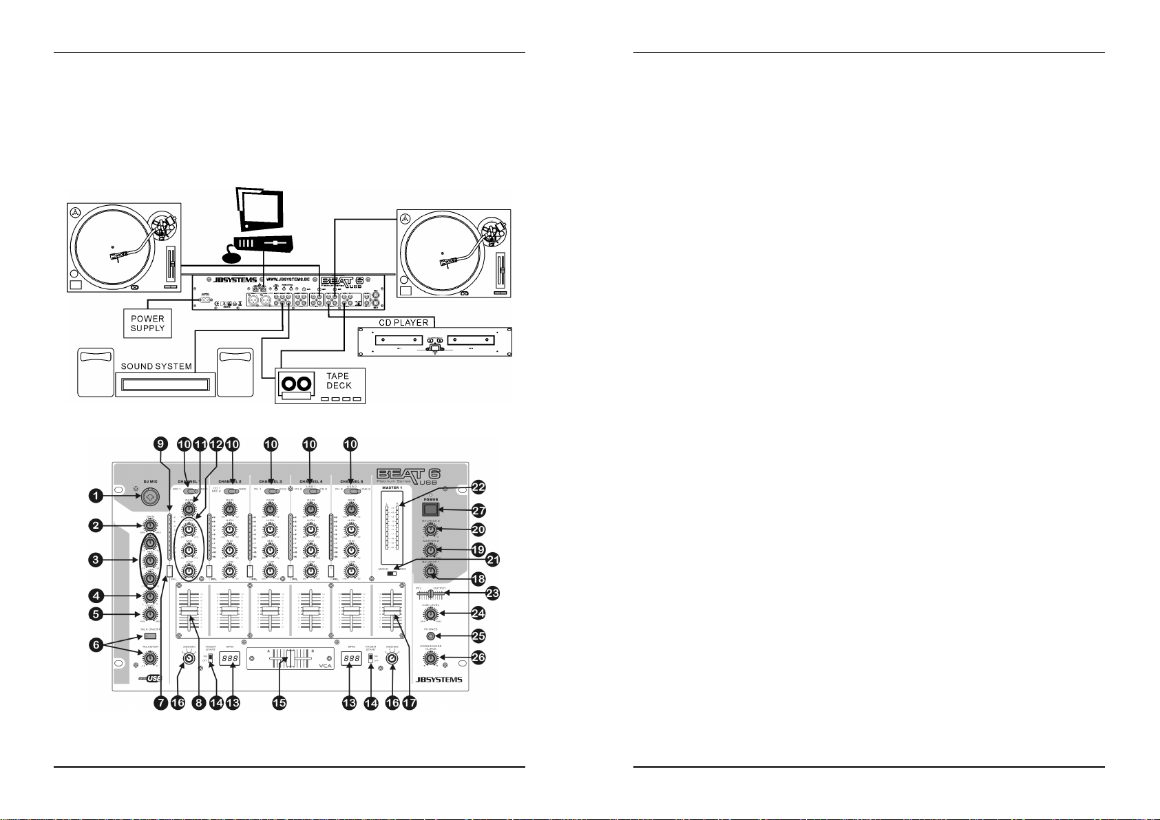
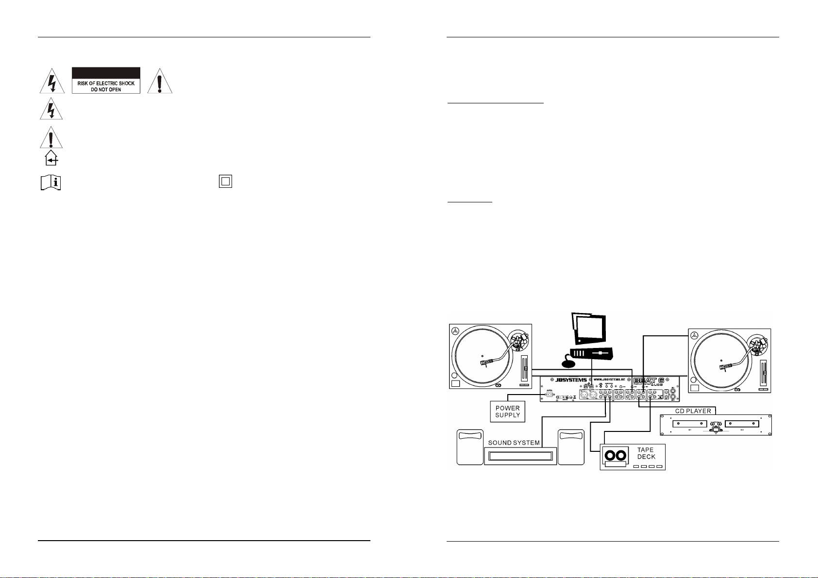
CONNECTIONS
Except for microphones, headphone and master outputs, all connections are cinch. Use good quality cinchcinch cables toprevent bad audio quality.
For more informationon connections, please refer to the next chapter.
Be sure to turn off the mixer before you make changes to the different connections.
In this manual we talk about “line inputs”. This is a global name for inputs with a level up to 2V.This includes
tuners,videos, CD-players, etc.
Both USB connections will be detected as a sound card on your computer. These connections are
bidirectional(play/recordmusic simultaneously)
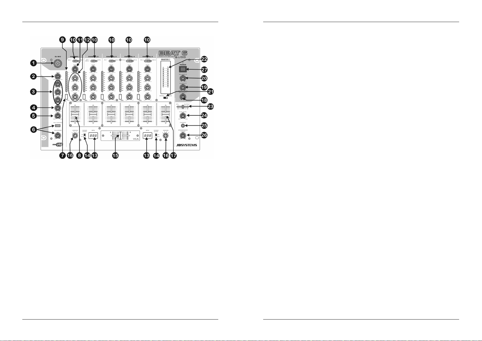
CONTROLS AND FUNCTIONS (FRONT)
1. DJ MIC INPUT JACK: Combo jack. Accepts either a balancedmicrophone with anXLR connector or an
unbalanced microphone with 1/4” mono jack. This input is mainly used as DJ-microphone. The talk over
does not affect the signal level of this input.
2. GAIN LEVEL: Adjusts the input level of the DJ input. Use this control to adjust the level of the DJ
microphoneon the VU-meterat about 0dB.
3. 3-BAND TONE CONTROL: The frequency of the DJ mic can be controlled overa +/-12dBrange.
4. PANPOT CONTROL: Used to locate the sound from the DJ mic somewherein the stereo field. A panpot
control does the same for mono signals as a balance control does for stereo signals.
5. DJ MIC VOLUME: Used to adjust the level of theDJ mic.
6. TALKOVER: Use the switch to automatically mute the input channels 1 to 5 while you are talking
through the DJ microphone. You can adjust the amount of muting on input channels 1 to 5. The more
you turn the talkover level to the right, the more these channels are muted while talking through the DJ
Mic(1).
7. PFL SELECTOR: Used to select the source (CH-1 to CH-5) to be monitored via the headphones output.
Pressing multiple Cue-buttons makesit possible to derive a mixed sound from the selectedsources.
8. CHANNEL FADER: Used to set the level of each channel separately. You can easily exchange this
fader with a new one. Later in this manual we explain how to do this.
9. CHANNEL VU METER: Each channel has its own LED VU-meter so you can adjust the gain level (11)
very quickly. Make sure the levels do not exceed 0dB (or 100%). The audio risks to be distorted when
the signal level comes in the red zone of the VU-meter.
10. INPUT SOURCE SELECTOR: Used to select the correct input on each channel: Phono, line, USB, aux
or mic. On some channels there are additional input selectors on the back.
Hint: Line, Aux, CD, Tuner, etc… are different names for inputs withalmost the same signal levels.
11. GAIN LEVEL: Adjusts the input level on each channel. Use this control to adjust the level on the VUmeterat about0dB.
12. 3-BAND TONE CONTROLS: The frequency of each channel can be controlled separately over a range
from -26dB to+12dB. In the center position the tone control is flat. (switched off)
13. BEAT COUNTER DISPLAY: Shows the number of beat per minute (BPM) of the music on the channel
selected with the crossfader assign selector (16). To have a reliable result on the display the music must
have a clear and steady beat.
14. FADER START ON/OFF SWITCH: When you have a compatible CD-player connected to the fader
control connectors, you can control its start/stop (re-cue) functions with the cross fader. With this switch
you can turn the fader start control on and off.
15. CROSSFADER: With this VCA fader you can mix over between the channels you selected with the
crossfaderassign selectors (16). The crossfader only works when you move the selected channel faders
(8) to the desired level! The crossfader also integrates the optical fader starts. See the next chapter for
more informationon this issue.
16. CROSSFADER ASSIGN: Selects the input channels to be used with the crossfader (16) and beat
counters(13). When set to “0” the crossfader is switched off.
17. MASTER1 LEVEL: Used toadjust thelevel ofthe balanced Master1 output.
(Attention:the “trim output” (43) on the back of the mixer can reduce the maximum output level of the
masteroutput fader. Check this trimmer ifthe maximum output level is below normal.)
18. BALANCE MASTER1: used toadjust thebalance between left and right output on Master1.
19. MASTER2 LEVEL: Used to adjust the level of theunbalanced Master2output.
20. BALANCE MASTER2: used toadjust the balance between left and right output on Master2.
21. MONO/STEREOSWITCH: used to switch master 1 in mono or stereo mode.
22. MASTER1 VU METERS: Monitors the output level of master1. Make sure the levels do not exceed 0dB
(or100%). The audio will be distortedwhen the signal level comes in the red zone of the VU-meter.
23. CUE MIX: With this fader you can mix the master output and any of the input channels through the
headphoneoutput (25):
Put the fader in the extremeleft position to monitora selected PFL signal (7).
Put the fader in the extremeright position to hear the master output.
Put the fader in any otherposition to hear a mix of the two signals.
This option makes it possible to check your mix before you put it on the master output.
24. CUE LEVEL: Used to controlthe output level of the headphone output.
25. HEADPHONE JACK: You can monitor all inputs/outputs when you connect any modern stereo
headphone to this 6.3mm jack.
26. CROSS FADER CURVE: Adjusts the curve of the cross fader from smooth (left position) to sharp (right
position).
27. POWER SWITCH: Used to turn the power of the mixer on and off. The blue led is lit when the mixer is
turned on.
JB SYSTEMS 3/44 BEAT6 USB
JB SYSTEMS 4/44 BEAT6 USB
Page 5
ENGLISH OPERATION MANUAL
ENGLISH OPERATION MANUAL
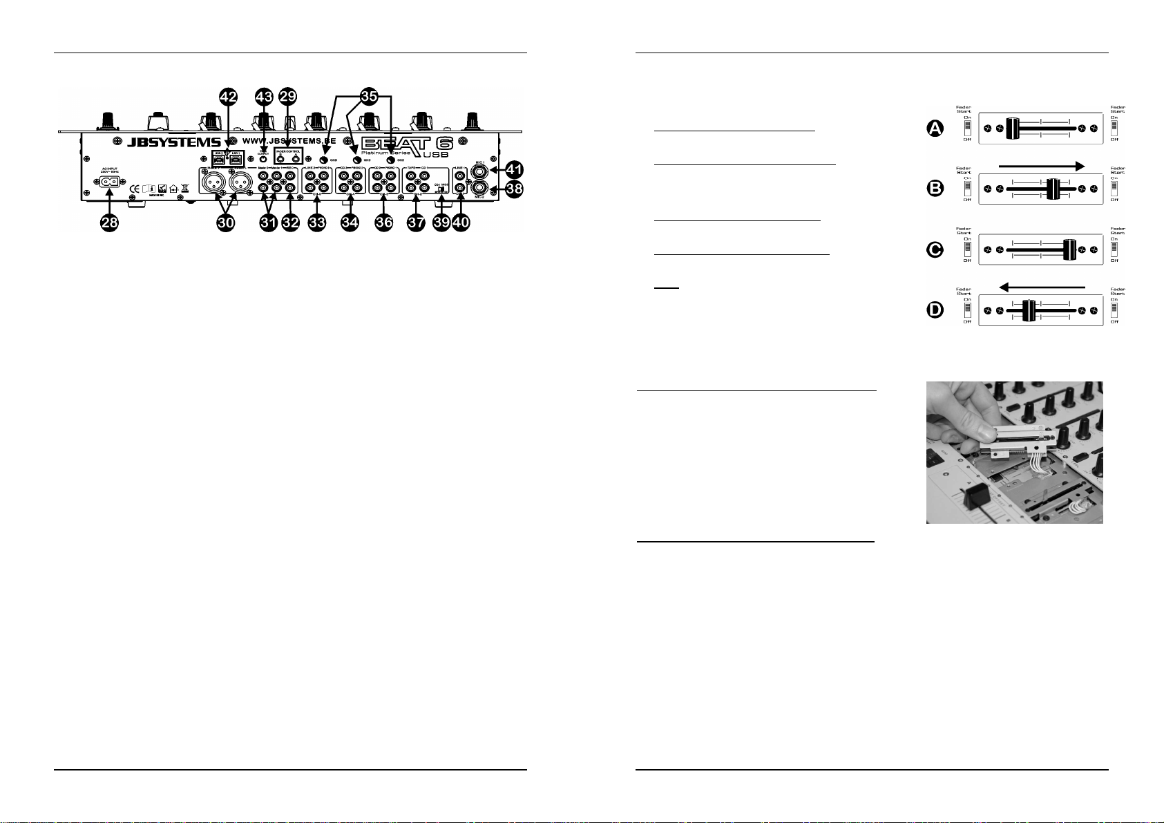
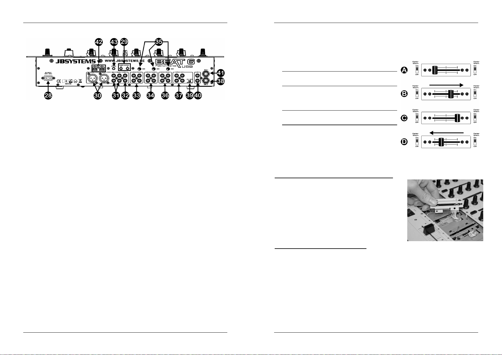
CONTROLS AND FUNCTIONS (rear)
28. MAINS CABLE: connect this cable to a 230V/50Hz mains outlet. Before use, inspect the cable to be
sure it’s not damaged!
29. FADER CONTROL: When connected to these inputs, compatible CD-players can be controlled by the
fader starts of this mixer.
30. MASTER1 BALANCED OUTPUT: The XLR-connectors can be used to connect this mixer to any
balanced amplifierinput, using special balanced signal cables.
31. MASTER UNBALANCED OUTPUTS: The “master 1” output has the same output signal as the
balanced master output(30) but unbalanced. The “master 2” output carries the same signal but can be
controlled independently by the master2 level/balance (19/20). Use the outputs to connect unbalanced
amplifiers.
32. RECORD OUTPUT: Carries the same signal as the master outputs but is not influenced by the master
level, balance and mono/stereo controls. Used to connect analog recording equipment. You can also
connect a computer for direct digital recording, see USB connections (42).
33. INPUT CHANNEL 5: used to connect two different line level audio signals. You can also connect a PC
via the USB connectors (see 42). The input source selector (10) on the front determines which input will
be active.
34. INPUT CHANNEL 4: used to connect a turntable and/or a line level audio signal. You can also connect a
PC via the USB connectors (see 42). The input source selector (10) on the front determines which input
will be active.
35. GROUND (GND) CONNECTION: Many Turntables have a GND-connection. It is preferable to connect
this signal ground to the GND-connector. If your turntable does not have a ground wire, you don’t have
to use this connector.
36. INPUT CHANNEL 3: used to connect a turntable and/or a line level audio signal. The input source
selector(10) on the front determineswhich input will be active.
37. INPUT CHANNEL 2: used to connect two different line level audio signals. Refer to switch (39) to
change oneline input to microphone level. The input source selector (10) on the front determines which
input will be active.
38. MIC2 INPUT: Used to connect a balanced microphone to channel 2. Refer to switch (39) to change the
CD1 input to mic2.
39. MIC2/CD1SWITCH: This switch makes it possible to switch between the CD1 input (37) and the mic2
input (38)onchannel2.
40. LINE INPUTCHANNEL1: used to connect a line level audio signal to channel1.
41. MIC1 INPUTCHANNEL1: used to connect a microphone to channel1.
42. USB CONNECTIONS: two bidirectional USB connections (USB1 for CH4 ~ USB2 for CH5). You can
connect any PC through these USB connections. The PC/Mac will detect your mixer as a sound card,
normally no drivers are needed. Since both USB ports are bidirectional you are able to play music on
your computer and mix this music with other sources like CD, phono, etc. At the same time you can
record your mix on your computer with the same USB connection!
43. OUTPUT TRIMMER: This potentiometer is used to reduce the output level of the mixer to protect the
connected amplifiers and speaker cabinets. (Attention: the output level can be reduced to zero. If you
don’t have any signal on the master output, first check if this potentiometeris accidentally put to zero.)
CROSSFADER STARTS
The crossfader integrates the optical fader start switches. These fader starts are compatible with all current
JB Systems CD-players. This is how it works:
A. CROSSFADER IN LEFT POSITION:
CD-playerconnected to fader start connector A is playing,
the other CD-playeris paused.
B. CROSSFADER MOVES TO THE RIGHT:
CD-player connected to fader start connector A stops
playing, returns toits previously programmed cue point and
waits in pause. The other CD-player starts playing from its
previouslyprogrammed cue point.
C. CROSSFADER IN RIGHT POSITION:
CD-player connected to fader start connector B is playing,
the other CD-playeris paused.
D. CROSSFADER MOVES TO THE LEFT:
CD-player connected to fader start connector B stops
playing, returns toits previously programmed cue point and
waits in pause. The other CD-player starts playing from its
previouslyprogrammed cue point.
Important:Both fader startswitches must be in “ON” position!
CHANGING THE FADERS
One of the big advantages of this mixeris the possibility to change the channel faders
This is what you must do to change a channel fader:
Remove the fader knobs from the faders.
Remove the 8 screws that hold the small front panel around
the faders.
Remove the 3 screws of the fader you want to change.
Gently remove the fader from its position and unplug the
connectorfrom the main board.(do NOT pull the cable!)
Put the new fader gently in place. Be sure to plug the
connectorin the connector base on the mixer PCB-board.
Put the 3 screws from the fader back in place
Put the small front plateback in place with the 8 screws.
Done!
This is what you must do to change the cross fader:
Remove the fader knob from the cross fader.
Remove the 2 screws that keepthe cross fader in place.
Gently remove the fader and the cover plate from their position.
Unplug the cross fader from the cable (unplug the cable by pulling the connector,NOTthe cable!)
Press the new cross fader on the cable.
Put the cross fader back in place with the small cover plate and the 2 screws.
Done!
JB SYSTEMS 5/44 BEAT6 USB
JB SYSTEMS 6/44 BEAT6 USB
Page 6
ENGLISH OPERATION MANUAL
SPECIFICATIONS
Power Supply: AC230 V, 50Hz (34Watt)
Frequencyresponse: 20-20.000Hz(+/-3dB)
THD + noise: <0.05% @ 1kHz, 0dB, load= 47kΩ
S/N Ratio (IHF-A): >78dB @ 1kHz.
USBconnections: USB 2.0, bidirectional(44,1kHz/ 16bit)
USB cable (not included): Lmax = 3m
Mic inputs: 2mV @ 3kΩ
Line/CDinputs: 340mV @ 47kΩ
Phonoinputs: 3mV @ 47kΩ
Record output: 775mV @ 1kΩ
Master1/2 output: 1.55V @ 1kΩ unbal.
Master 1 output: 2,55V @ 600Ω bal.
Talkover: 0dB -14dB
Channel tonecontrols: +12dB / -26dB (70Hz,1kHz,13kHz)
DJ Mic tone controls: +12dB/ -12dB(70Hz,1kHz,13kHz)
Headphone: 3V@32Ω
Dimensions: 483(W) x 310(D) x 112(H)mm (19”/7U)
Weight: 6,9kg
You can download the latest version of thisuser manual on our website: www.beglec.com
Every informationis subject to change withoutprior notice
Windows®& MacOS®compatible.
FRANCAIS MODE D’EMPLOI
Nous vous remercions d’avoir acheté ce produit JB Systems®. Veuillez lire ce mode d’emploi très
attentivement afin de pouvoir exploitertoutesles possibilités de cet appareil.
EN VOUS INSCRIVANT POUR LA LETTRE D’INFORMATION VOUS SEREZ TOUJOURS
TENU AU COURANT DES DERNIERES NOUVELLES CONCERNANT NOS PRODUITS:
NOUVEAUTES,ACTIONS SPECIALES,JOURNEES PORTES OUVERTES, ETC.
SURFEZ SUR: WWW.BEGLEC.COM ET INSCRIVEZ-VOUS
CARACTERISTIQUES
Cet appareil ne produit pas d’interférences radio. Il répond aux exigences nationales et européennes. La
conformité aété établie et les déclarationset documentscorrespondants ont été déposés par le fabricant.
14 entrées sur 6 canaux (6 lignes, 3 phonos, 3 micros, 2 USB)
2connexionsUSB bidirectionnelles
1 micro DJ séparé avec talkover
Contrôle du Gain, des aigus, médiums etbasses sur tous les canaux
Crossfaderassignable, facilementremplaçable
Curseurs DJ de type «steel rail» de haute qualité, avecun déplacementagréable au toucher
(curseurs dotés de rails en acier pour une plus longue durée devie)
2 sorties Master avec contrôle de balance individuelle
Master1 avec sorties XLR symétriques et réglage de niveau du signal
VU-mètresLED sur les canaux d’entrés et le master 1
Compteursde temps (beatcounters)automatiques ettrèsprécis
Démarragepar Crossfader pour les lecteurs CD compatibles
Pré écoute« Pre-fader » avec option cue mix
JB SYSTEMS 7/44 BEAT6 USB
AVANT L'UTILISATION
Quelquesinstructionsimportantes:
Avant d’utiliser cet appareil, assurez-vous de l’absence de dommage lié au transport. En cas
d’endommagement,n’utilisezpas l’appareil et contactez le vendeur.
Important:
l’utilisateur suive les instructions de sécurité et avertissements inclus dans ce manuel. La garantie ne
s’applique pas en cas de dommage lié à une utilisation incorrecte. Le vendeur ne prend pas la
responsabilité des défauts ou de tout problème résultant du fait de n’avoir pas tenu compte des mises en
garde de ce manuel.
Conservez ce manuel dans un endroit sûr pour toute consultation future. Si vous vendez l’appareil,
assurez-vous d’y joindre ce manuel également.
Afinde protéger l’environnement, mercide recycler les emballages autant que possible.
Vérifier le contenu:
Vérifiezque l'emballage contienneles différentséléments:
Table de mixage
Moded'emploi
Câbled’alimentation
JB SYSTEMS 8/44 BEAT6 USB
Cet appareil a quitté notre usine en parfaite condition et bien emballé. Il est primordial que
Page 7
FRANCAIS MODE D’EMPLOI
FRANCAIS MODE D’EMPLOI
INSTRUCTIONS DE SECURITE
ATTENTION: afin de réduire le risque d’électrocution,
CAUTION
qualifiés.
La flèche dans un triangle met l'utilisateur en garde contre la présence de haute tension sans
isolationdans l'appareil,ce qui peut causer un risque d'électrocution.
Un point d'exclamation dans un triangleprévient de la présence d'instructions relativesau
fonctionnement et à la maintenancese trouvant dans le manuel fourniavec l'appareil.
Ce symbole signifie : uniquement pour usage à l'intérieur.
Ce symbole signifie : Lire le mode
Afin d’éviter tout risque d’incendie ou de décharge électrique, ne pas exposer cet appareil à la pluie ou
Pour éviter la formation de condensation à l’intérieur de l’appareil, patientezquelques minutes pour laisser
Cetappareil est destiné à une utilisation à l’intérieur uniquement.
Ne pas insérer d’objet métallique ou renverser de liquide dans l’appareil. Aucun objet contenant un liquide,
Aucune source de flamme nue, telleque des bougies allumées, ne peut être placée sur l'appareil.
Ne pas couvrir les orifices de ventilation, un risque de surchauffe en résulterait.
Ne pas utiliserl'appareil dans un environnement poussiéreux et le nettoyerrégulièrement.
Ne pas laisser l'appareil à portée des enfants.
Les personnes non expérimentées ne doivent pas utiliser cet appareil.
La températureambiante maximale d’utilisation de l’appareilest de 45°C. Ne pas l’utiliser au-delà de cette
Rien ne doit se trouver contre l'appareil : la distance minimum pour en permettre une ventilation suffisante
Débranchez toujours l’appareil si vous ne l’utilisez pas de manière prolongée ou avant d’entreprendredes
Les installations électriques ne peuvent être faites que par du personnel qualifié et conformément aux
Assurez-vous que la tension d’alimentation de la source d’alimentationde la zone dans laquelle vous vous
La prise doit toujours êtreaccessible pour que le cordon secteur puisse être enlevé à tout moment.
Le cordon d’alimentation doit toujours être en parfait état. Mettez immédiatement l’unité hors tension si le
Ne laissez jamais le cordon d’alimentation entreren contact avecd’autres câbles !
Quand l’interrupteur principal est en position OFF, cet appareil n'est pas complètement isolé du courant
Utiliseztoujours des câbles appropriés et certifiés lorsque vous installezl’appareil.
Pour éviter toute décharge électrique, ne pas ouvrir l’appareil. En dehors du fusible principal, il n’y a pas
d’emploi.
l’humidité.
l’appareil s’adapter à la température ambiante lorsqu’il arrive dans une pièce chauffée après le transport.
La condensation empêche l'appareil de fonctionner de manière optimale, et elle peut même causer des
dommages.
tels que des vases, ne peut être placé sur cet appareil. Cela risquerait de provoquer une décharge
électrique ou un dysfonctionnement. Si un corps étranger est introduit dans l’appareil, déconnectez
immédiatement de la source d’alimentation.
température.
est de 5cm.
réparations.
règlements de sécurité électrique et mécanique en vigueurdans votre pays.
trouvezne dépasse pas celle indiquée à l’arrière de l’appareil.
cordon devait être écrasé ou endommagé. Pour éviter tout risque de choc électrique, le cordon doit être
remplacé par le constructeur, son agent ou un technicien qualifié.
230V !
de pièces pouvantêtrechangées par l’utilisateurà l’intérieur.
Ne jamais
un fusible de même type et ayant lesmêmes spécificationsélectriques !
réparer ou court-circuiter un fusible. Remplacez
n’enlevez jamais le couvercle de l’appareil. Il n’y a aucune
pièce à l’intérieur de l’appareil que vous puissiez remplacer
vous-même. Confiezl’entretien uniquement à des techniciens
Ce symbole signifie: appareilconstruit
selon les normes de sécurité classe II
systématiquement
un fusible endommagé par
En cas de problèmes de fonctionnement sérieux, arrêtez toute utilisation de l’appareil et contactez votre
revendeurimmédiatement.
Utilisezl’emballaged’origine si l’appareil doit êtretransporté.
Pour des raisons de sécurité, il est interdit d’apporter une quelconque modification à l’appareil non
spécifiquement autoriséepar les partiesresponsables.
CONSEILS D'INSTALLATION:
Installerl'appareil dans un lieu bien aéré, à l'abri de l'humidité et des fortes températures.
Placer et utiliser l'appareil à proximité de sources de chaleur telles que spots, amplis,… pourrait affecter
ses performances et même endommager l'appareil.
L'appareil peut être installé dans un rack 19''. Fixer l'appareil en utilisant les 4 trous pour vis sur la face
avant. Assurez-vous d'utiliser des vis de la bonne dimension (vis non fournies). Essayez d'éviter les
vibrationset les coups lors du transport.
En cas d'installation dans un 'flight case', assurer une bonne ventilation afin d'évacuer la chaleur produite
par l'appareil.
Pour éviter la condensation à l'intérieur, laisser l'appareil s'adapter à la nouvelle température ambiante
après le transport. La condensationpeut altérer les performancesde l'appareil.
NETTOYAGE:
Nettoyer en frottant à l'aide d'un chiffon doux très légèrement humide. Eviter de verser de l'eau dans
l'appareil. Ne pas utiliserde liquides abrasifs qui pourraient endommager l'appareil.
CONNEXIONS
A l'exception des micros, du casque et des sorties master, toutes les connexions sont au standard Cinch.
Utilisezdes câbles cinch/cinch de bonne qualité afin d'éviter un son de mauvaisequalité.
Pour plus d'informations sur les connexions, voyez le chapitre suivant.
Assurez-vous d'éteindre la table de mixage avant d'effectuer les différentes connexions. Dans ce mode
d'emploi,il est question d'entrée ligne ou “line inputs”. Il s'agit en fait d'un terme génériquepourdésignerdes
entréesallant jusqu'à un niveau de 2V. Ceci inclut les lecteursdeCD, tuners, vidéos,…
Les deux connexions USB seront détectées par votre ordinateur en tant que cartes son. Ces connexions
sont bidirectionnelles: elle autorisent donc simultanément la lectureet l'enregistrement.
JB SYSTEMS 9/44 BEAT6 USB
JB SYSTEMS
®
10/44 BEAT6 USB
Page 8
FRANCAIS MODE D’EMPLOI
FRANCAIS MODE D’EMPLOI
CONTROLES ET FONCTIONS (FACE AVANT)
1. DJ MIC INPUT JACK: jack Combo. Accepteles micros symétriquespourvus d’un connecteur XLR, ainsi
que les micros asymétriques pourvus d’un connecteur jack mono de 1/4”. Cette entrée est
principalement utilisée pour le micro DJ. Le talkover n’affectepas le niveau du signal de cette entrée.
2. GAIN LEVEL: règle le niveau d’entré du micro DJ. Utilisez ce potentiomètre pour régler le niveau du
microDJ jusqu'à ce que vous atteigniezles 0dB sur le VU-mètre.
3. REGLAGE DE TONALITÉ à 3 bandes: la fréquence du micro DJ peut être réglé avec une portée de +/12dB.
4. REGLAGE PAN: est utilisé pour placer le son du micro DJ à un endroit précis dans le champs stéréo.
Un réglage« pan » fait la même chose pour les signaux mono, comme le fait le contrôle de balance pour
les signaux stéréo.
5. DJ MIC VOLUME: Est utilisé pour réglerle niveau du micro DJ.
6. TALKOVER: utilisez cet interrupteur pour atténuer automatiquement les canaux d’entrés 1 à 5 pendant
que vous parlez dansle micro DJ. Vous pouvezrégler le niveau d’atténuation des canaux d’entrés 1 à 5.
Au plus que vous tournez le bouton « talkover » vers la droite, au plus ces canaux seront atténués
pendant que vous parlez dans le micro DJ (1).
7. SELECTEUR PFL: est utilisé pour sélectionner la source (CH-1 à CH-5) que vous voulez pré écouter
par la sortie casque. Si vous enfoncez plusieurs touches Cue, il est possible d’obtenir un son mixé des
sourcessélectionnés.
8. CURSEUR / CANAL: sont utilisés pour régler le niveau de chaque canal séparément. On peut
facilement remplacer ce curseur par un nouvel élément. Dans un des chapitres suivants de ce mode
d'emploi,nous expliquons la procédure pour effectuerce remplacement.
9. VU MÈTRE/ CANAL: chaque canal possède son propre VU-mètre LED ce qui vous permet de régler le
niveau gain (11) très rapidement. Faites attention que les niveaux ne dépassent pas 0dB (ou 100%). Le
signal audio risque d’être déformé si le niveau du signal entredans la zone rougedu VU-mètre.
10. SELECTEUR DE SOURCE D’ENTRÉE: est utilisé pour sélectionner la source d’entrée exacte pour
chaque canal: Phono, line, USB, aux ou mic. Sur quelques canaux il y a des sélecteurs d’entrés
supplémentaires à l’arrière de la table de mixage.
Avis: Line, Aux, CD, Tuner, etc… sont différents noms pour des entrées qui ont un niveau de signal
pratiquementidentique.
11. GAIN LEVEL: règle le niveau d’entré de chaque canal. Utilisez ce bouton pour régler le niveau jusqu'à
ce que vous atteigniez les 0dB sur le VU-mètre.
12. Réglage de TONALITÉ à 3 bandes: la fréquence de chaque canal peut être réglé séparément dans
une plage allant de -26dB à+12dB. Dans la position centrale,le contrôle de tonalitéest neutre. (éteint)
13. BEAT COUNTER DISPLAY: affiche le nombre de « beats » (battements) par minute (BPM) de la
musique du canal sélectionné par le sélecteur d’assignement du crossfader (16). Pour obtenir un
résultat fiable sur le cadran, il fautque la musique ait un « beat » clair et constant.
14. INTERRUPTEUR FADER START ON/OFF: quand vous avez un lecteur CD compatible connecté aux
connecteurs « fader control », vous pouvez contrôler ses fonctions départ/arrêt (re-cue) avec le cross
fader. Avec cet interrupteur vous pouvez engager ou désengager la fonction fader start.
15. CROSSFADER: avec ce curseur VCA vous pouvez mixerles canaux que vous avez sélectionnés avec
les sélecteurs d’assignement du crossfader (16). Le crossfaderne fonctionnera que sivous avez réglés
les curseurs des canaux (8) sélectionnés au niveau désiré! Le crossfader est également pourvu de
interrupteurs optiques de démarrage. Voyez le chapitre suivant pour plus d’informations à ce sujet.
16. CROSSFADERASSIGN: sélectionne les canaux d’entrés qui seront utilisés avec le crossfader (16) et
les compteurs debattements« beat counter » (13). Si vous les mettezsur “0” le crossfaderest coupé.
17. NIVEAUMASTER1: est utilisé pour régler le niveau de la sortiesymétrique Master1.
(Attention: le délimiteur “trim"(43) à l'arrière de la table peut réduire le niveau de sortie maximal du
curseur de sortiemaster1. Vérifiez ce délimiteur (trim)si le niveau de sortie maximal est plus bas que la
normale.
18. BALANCE MASTER1: est utilisé pour régler la balance entre la sortie gauche et droite du Master1.
19. NIVEAUMASTER2: est utilisé pour régler le niveau de la sortie asymétrique Master2.
20. BALANCE MASTER2: est utilisé pour régler la balance entre la sortie gauche et droite du Master2.
21. SELECTEUR MONO/STEREO: est utilisé pour mettre les deux sorties Master en mode mono ou stéréo.
22. VU MÈTRES MASTER1: affiche le niveau de sortie du master1. Faites attention que les niveaux ne
dépassent pas 0dB (ou 100%). Le son risque d’être déformé si le niveau du signal entre dans la zone
rougedu VU-mètre.
23. CUE MIX: avec ce curseur vous pouvez mixer la sortie master avec n’importequel canal d’entré dans la
sortiecasque(25):
Mettezle curseur complètement à gauche pour pré écouter le signal PFL sélectionné (7).
Mettezle curseur complètement à droite pour écouter la sortie master.
Mettez le curseur dans une autre position pour écouter le mixagedes deux signaux.
Cetteoption vous permet de vérifiervotre mixageavant que vous l’envoyiezvers la sortie master.
24. CUE LEVEL: est utilisé pour régler le niveaude la sortie casque.
25. HEADPHONE jack: Vous pouvez pré écouter toutes les entrées/sorties en connectant n’importe quel
casque stéréo moderne à ce jack de 6.3mm.
26. CROSS FADER CURVE: Règle la courbe du cross fader : transition douce = position gauche, transition
brusque = position droite.
27. Interrupteur POWER: est utilisé pour allumer ou éteindre la table de mixage. Le Led bleu est allumé
quand la table de mixageest allumée.
JB SYSTEMS
®
11/44 BEAT6 USB
JB SYSTEMS
®
12/44 BEAT6 USB
Page 9
FRANCAIS MODE D’EMPLOI
FRANCAIS MODE D’EMPLOI
CONTROLES ET FONCTIONS (FACE ARRIERE)
28. CÂBLE D’ALIMENTATION: connectez ce câble au secteur 230V/50Hz. Vérifiez toujours si le câble
n’est pas endommagéavantdel’utiliser !
29. FADER CONTROL: quand des lecteurs CD compatibles sont connectés a ces entrées, ils peuvent être
contrôlés par les fader starts de cette table de mixage.
30. SORTIE SYMETRIQUE MASTER1: les connecteurs XLR peuvent être utilisés pour connecter cette
table de mixage a n’importe quelle entrée symétrique d’amplificateur en utilisant un câble de signal
symétriquespécifique.
31. SORTIES MASTER ASYMETRIQUES: la sortie “master 1” transmet le même signal de sortie que la
sortie master symétrique (30), mais est dans ce cas asymétrique. La sortie “master 2” transmet le même
signal mais peut être réglé indépendamment par le master 2 level/balance (19/20). Utilisez ces sorties
pour connecter des amplificateurs asymétriques.
32. RECORD OUTPUT: transmet le même signal que les sorties master, mais n’est influencé ni par le
niveau du master, ni par le réglage de la balance, ni par le sélecteur mono/stéréo. Il est utilisé pour
brancher un enregistreuranalogique. Vous pouvezégalement connecterun ordinateur pour effectuer un
enregistrementdigital direct, veuillezvous reporterpour cela au N° 42, 'Connexions USB'.
33. INPUT CHANNEL 5: est utilisé pour connecter deux signaux audio différents du niveau Line. Vous
pouvezégalement connecter un ordinateur via les connecteurs USB (se reporterau N° 42). Le sélecteur
de source d’entrée (10) sur la face avant déterminequelle source sera activée.
34. INPUT CHANNEL 4: estutilisée pour connecter une platine vinyle et/ou un signal audio du niveau Line.
Vous pouvez également connecter un ordinateur via les connecteurs USB (se reporter au N° 42). Le
sélecteur de source d’entrée (10) sur la faceavant détermine quelle source sera activée.
35. GROUND (GND) CONNECTION: Beaucoup de platines vinyle sont équipés d’un connecteur de masse
(GND). Il est conseillé de connecter ce signal de masse au connecteur GND. Si votre platinevinyle ne
dispose pas d’un câble de masse, vous ne devez pasutiliser ce connecteur.
36. INPUT CHANNEL 3: estutilisée pour connecter une platine vinyle et/ou un signal audio du niveau Line.
Le sélecteur de source d’entrée (10) sur la face avant déterminequelle source sera activée.
37. INPUT CHANNEL 2: est utilisée pour connecter deux signaux audio différents de niveau ligne. Utilisez
l’interrupteur (39) pour changer une entrée Line en entrée micro. Le sélecteur de source d’entrée (10)
sur la face avant détermine quelle source sera activée.
38. INPUT MIC2 : est utilisée pour connecterun microsymétrique au canal 2. Utilisez l’interrupteur(39) pour
changerl’entrée CD1 en micro 2.
39. INTERRUPTEUR MIC2/CD1: cet interrupteur vous offre la possibilité de sélectionner soit l’entrée CD1
(37), soit l’entrée micro 2 (38) pour le canal 2.
40. LINE INPUTCHANNEL1: est utilisée pour connecter un signal audio du typeLine au canal 1.
41. MIC1 INPUTCHANNEL1: est utilisée pour connecter un micro au canal1.
42. CONNEXIONS USB : deuxconnexions USB bidirectionnelles (USB1 pour le CH4 et USB2 pour le CH5).
Vous pouvez connecter n'importe quel ordinateur via ces connexions USB. Le PC/Mac détectera votre
mixer en tant que carte son, donc en principe, aucun pilote n'est nécessaire. Etant donné que les deux
ports USB sont bidirectionnels, vous êtes en mesure de reproduire de la musique au départ de votre
ordinateur et de mélanger cette musique avec d'autres sources comme celles d'un lecteur CD, d'un
phono, etc … Mais en même temps, vous pouvez également enregistrer votre 'mix' dans votre
ordinateur via cettemême connexion USB !
43. SORTIE TRIM: ce potentiomètre permet de limiter et donc, de réduire le niveau de sortie de la table de
mixage afin d'éviter d'endommager l'ampli ou les haut-parleurs. (Attention: le niveau de sortie peut
descendre jusqu'à zéro. S'il n'y a pas de signal sur la sortie master, vérifier que ce potentiomètre n'ait
pas été mis accidentellement sur zéro.)
CROSSFADER START
Le crossfader est pourvu d’interrupteurs optiques de démarrage. Ces faderstart sont compatibles avec tous
les lecteurs CD JB Systems actuels. Voici comment cela
fonctionne:
A. CROSSFADER COMPLETEMENT À GAUCHE:
Le lecteur CD relié au connecteur fader start A joue, l’autre
lecteur CD est en attente.
B. CROSSFADER BOUGE VERS LA DROITE:
Le lecteur CD relié au connecteur fader start A arrête de
jouer, retourne à son point « cue » préprogrammé et se met
en attente. L’autre lecteur CD commence à jouer à partir de
son point « cue» préprogrammé.
C. CROSSFADER COMPLETEMENT Á DROITE:
Le lecteur CD relié au connecteur fader start B joue, l’autre
lecteur CD est en attente.
D. CROSSFADER BOUGE VERS LA GAUCHE:
Le lecteur CD relié au connecteur fader start B arrête de
jouer, retourne à son point « cue » préprogrammé et se met
en attente. L’autre lecteur CD commence à jouer à partir de
son point « cue» préprogrammé.
Important: Les deux interrupteurs du faderstart doivent être en
position“ON”!
REMPLACEMENT DES CURSEURS
Un grand avantage de cette table de mixageest de pouvoir remplacer les curseurs des canaux.
Voici laprocédure pour remplacer les curseurs des canaux:
Retirer les boutons des curseurs.
Retirer les 8 vis du panneau frontalqui entoureles curseurs.
Retirer les 3 vis du curseur que vous souhaitez remplacer.
Retirez délicatement le curseur de son emplacement et
débranchez le connecteur de la carte mère (surtout, NE tirez
PAS sur le câble !).
Mettez délicatement le nouveau curseur en place. Ne pas
oublier de rebrancher le connecteur du nouveau curseur au
connecteur de la carte mère du mixer.
Remettezles 3 vis du curseur en place.
Remettezle petit panneau frontal en placeà l'aide des 8 vis.
C'est fait!
Voici la procédure pourchanger le crossfader:
Retirer les boutons du crossfader.
Retirez les 2 vis qui maintiennent le crossfader.
Retirez délicatement le curseur et le plateau de leur emplacement.
Débranchez le câble du crossfader (tirez sur le connecteur,PAS sur le câble!)
Branchez le nouveaucrossfadersur le câble.
Remettrele crossfader et son petit plateau en place à l'aide des 2 vis.
C'est fait!
JB SYSTEMS
®
13/44 BEAT6 USB
JB SYSTEMS
®
14/44 BEAT6 USB
Page 10

FRANCAIS MODE D’EMPLOI
CARACTERISTIQUES TECHNIQUES
Alimentation: AC230 V, 50Hz (34Watt)
Réponse de fréquence: 20-20.000Hz(+/-3dB)
DHT + bruit: <0.05% @1kHz, 0dB, charge = 47kΩ
S/N Ratio (IHF-A): >78dB @ 1kHz.
Connexions USB : USB 2.0 bidirectionnelle(44,1 kHz/16bit)
Câble USB (pas inclusif): L
Entrées micro: 2mV@ 3kΩ
EntréesLine/CD: 340mV @ 47kΩ
Entrées Phono: 3mV @ 47kΩ
Sortie Record: 775mV @ 1kΩ
Sortie Master 1/2: 1.55V @ 1kΩ unbal.
Sortie Master 1: 2,55V @ 600Ω bal.
Talkover: 0dB -14dB
Contrôle de tonalité des canaux : +12dB / -26dB (70Hz, 1kHz, 13kHz)
Contrôle de tonalité du micro DJ : +12dB / -12B (70Hz, 1kHz, 13kHz)
Casque: 3V@32Ω
Dimensions: 483(L) x 310(H) x 112(P)mm (19”/7U)
Poids: 6,9kg
Chacune de ces informationspeut être modifiéesans avertissement préalable. Vous pouvez
télécharger la dernière version de ce mode d’emploide notre siteWeb: www.beglec.com
compatibleWindows®& Mac OS
= 3m
max
®
NEDERLANDS GEBRUIKSAANWIJZING
Hartelijk dank voor de aankoop van dit JB Systems®product. Om ten volle te kunnen profiteren van alle
mogelijkheden en voor uw eigen veiligheid, gelieve de aanwijzingen zeer zorgvuldig te lezen voor U begint
het apparaat te gebruiken.
DOOR U OP ONZE MAILINGLIJST IN TE SCHRIJVEN ONTVANGT U STEEDS DE
LAATSTE INFORMATIE OVER ONZE PRODUKTEN: NIEUWIGHEDEN,SPECIALE
SURF NAAR: WWW.BEGLEC.COM EN SCHRIJF U IN
ACTIES, OPENDEURDAGEN, ENZ.
KARAKTERISTIEKEN
In dit apparaat is radio-interferentieonderdrukt. Dit product voldoet aan de gangbare Europese ennationale
voorschriften. Het is vastgesteld dat het apparaat er zich aan houdt en de desbetreffende verklaringen en
documenten zijn door de fabrikantafgegeven.
14 ingangen over 6 kanalen (6line, 3phono, 3micro,2USB)
2 bidirectionele USB aansluitingen ( tezelfdertijd afspelenen opnemen )
1 DJ microfooningang met talkover
Gain, treble, mid, bass regeling op alle kanalen
Toewijsbareen gemakkelijkvervangbare crossfader
Vlotglijdende “steel rail” DJ schuifregelaars van hoge kwaliteit
2 Masteruitgangen met individuele balansregeling
Master1met gebalanceerde XLR uitgangen en signaalbegrenzing
LED VU-meters op de ingangskanalen en master 1
Zeeraccurate automatische beat counters
Crossfaderstarts voorcompatibele CD spelers
Pre-fadevoorbeluisteringmet cue mix optie
JB SYSTEMS
VOOR GEBRUIK
Belangrijkeinstructies:
Controleervoor het eerste gebruik van het apparaat of het tijdens het transport beschadigd werd. Gebruik
hetapparaatbij beschadiging niet,raadpleeg eerstuw dealer.
Belangrijk:
de gebruiker de veiligheidsaanwijzingen en raadgevingen in deze gebruiksaanwijzing uiterst nauwkeurig
volgt. Elke schade veroorzaakt door verkeerd gebruik van het apparaat valt niet onder de garantie. De
dealer aanvaardt geen verantwoordelijkheid voor mankementen en problemen die komen door het
veronachtzamenvandezegebruiksaanwijzing.
Bewaar deze brochure op een veilige plaats om hem in de toekomst nogmaals te kunnen raadplegen.
Indien U het apparaatverkoopt, denkt U er wel aan om de gebruiksaanwijzing bij tevoegen.
Om het milieu te beschermen,probeer zoveel mogelijk het verpakkingsmateriaalte recycleren.
Controleer de inhoud:
Kijk na of de doos volgende producten bevat:
Mixer
Handleiding
Netsnoer
®
15/44 BEAT6 USB
JB SYSTEMS 16/44 BEAT6 USB
Dit apparaat verliet de fabriek in uitstekende staat en goed verpakt. Het is erg belangrijk dat
Page 11

NEDERLANDS GEBRUIKSAANWIJZING
NEDERLANDS GEBRUIKSAANWIJZING
VEILIGHEIDSVOORSCHRIFTEN:
WAARSCHUWING: Om het risico op elektrocutie zoveel
CAUTION
De bliksempijl die zich in een gelijkbenige driehoek bevindt is bedoeld om u te wijzen op het
gebruik of de aanwezigheidvan niet-geïsoleerde onderdelen met een “gevaarlijke spanning” in het
toesteldie voldoendekracht heeft om een risico van elektrocutiein te houden.
Het uitroepteken binnen de gelijkbenige driehoek is bedoeld om de gebruiker erop te wijzen dat er
in de meegeleverde literatuur belangrijke gebruik en onderhoudsinstructies vermeld staan
betreffendedit onderdeel.
Dit symbool betekent: het apparaat mag enkel binnenhuis wordengebruikt.
Dit symbool betekent: Lees de
handleiding!
Stel dit apparaat niet bloot aan regen of vocht, dit om het risico op brand en elektrische schokken te
voorkomen.
Om de vorming van condensatie binnenin tevoorkomen, laat het apparaat aan de omgevingstemperatuur
wennen wanneer het, na het transport, naar een warm vertrek is overgebracht. Condensatie kan het
toestel soms verhinderen perfect te functioneren. Het kan soms zelfs schade aan het apparaat
toebrengen.
Gebruikditapparaat uitsluitend binnenshuis.
Plaats geen stukken metaal en mors geen vocht binnen in het toestel om elektrische schokken of storing
te vermijden. Objecten gevuld met water, zoals bvb. Vazen, mogen op dit apparaat worden geplaatst.
Indien er toch een vreemd voorwerp of water in het apparaat geraakt, moet U het direct van het lichtnet
afkoppelen.
Open vuur, zoals brandende kaarsen, mogen niet op het apparaat geplaatst worden.
Bedekgeen enkele ventilatieopeningom oververhitting te vermijden.
Zorg dat het toestel niet in een stoffige omgeving wordt gebruikt en maak het regelmatigschoon.
Houd het apparaatuit de buurt van kinderen.
Dit apparaat mag niet door onervaren personenbediend worden.
De maximum veilige omgevingstemperatuur is 40°C. Gebruik het apparaat dus niet bij hogere
temperaturen.
De minimum afstand rondom dit apparaatom een goede koeling toe te laten is 5cm.
Trek altijd de stekker uit wanneer het apparaat gedurende langere tijd niet wordt gebruikt of alvorens met
deonderhoudsbeurttebeginnen.
De elektrische installatie behoort uitsluitend uitgevoerd te worden door bevoegd personeel, volgens de in
uw land geldende regels betreffendeelektrische en mechanische veiligheid.
Controleer dat de beschikbare spanning niet hoger is dan die aangegeven op de achterzijde van het
toestel.
Het stopcontact zal steeds vrij toegankelijk blijven zodat de stroomkabel op elk moment kan worden
uitgetrokken.
De elektrische kabel behoort altijd in uitstekendestaat te zijn. Zet het apparaat onmiddellijk af als de
elektrischekabel gekneusd of beschadigd is. De kabel moet vervangen worden door de fabrikant zelf, zijn
dealer of vergelijkbare bekwamepersonenom een brand te voorkomen.
Laat de elektrische draad nooit in contact komen met andere draden.
Als de netschakelaar zich in OFF (uit) positie bevindt dan is dit apparaat niet volledig van het lichtnet
gescheiden!
Om elektrische schokken te voorkomen,moet U de behuizing niet openen. Afgezien van de zekering zitten
er geen onderdelen in die door de gebruiker moeten worden onderhouden.
Repareer
steeds
nooit
een zekering en overbrug de zekeringhouder nooit. Vervang een beschadigde zekering
door een zekering van hetzelfdetype en met dezelfde elektrische kenmerken.
mogelijk te vermijden mag u nooit de behuizing verwijderen.
Er bevinden zich geen onderdelen in het toestel die u zelf kan
herstellen. Laat de herstellingen enkel uitvoeren door een
bevoegdetechnicus.
Dit symbool betekent: Klasse II
apparaten
Ingeval van ernstige problemen met het bedienen van het toestel, stopt U onmiddellijk het gebruik ervan.
Contacteeruw dealer voor een eventuele reparatie.
Gebruik best de originele verpakking als het toestelvervoerd moet worden.
Om veiligheidsredenenis het verboden om ongeautoriseerde modificatiesaan het toestelaan te brengen.
INSTALLATIEVOORSCHRIFTEN:
Plaats de mengtafel in een goed geventileerde ruimte waar zij niet blootgesteld is aan hoge temperaturen
of vocht.
Het plaatsen en het gebruik van de mengtafel gedurende een lange periode in de nabijheid
warmtebronnenzoalsversterkers,spots,enz. zal zijn werking beïnvloeden.
De mixer kan in een 19” kast gemonteerd worden. Monteer de behuizing door middel van de 4
montageopeningen op de frontplaat. Gebruik hiervoor bouten van de juiste dikte! (deze zijn niet
inbegrepen) Probeersterkeschokkenen vibraties tijdens het transport zo veel mogelijkte vermijden.
Zorg, bij inbouw in een vaste installatie of flightcase, voor een goede ventilatie om de warmte optimaal te
kunnen afvoeren.
Zorg ervoor,om inwendige vorming van condensatie te voorkomen, dat de mengtafelzichna transport kan
aanpassenaan de warmebinnentemperatuur.Condensatiekan de goede werking soms verhinderen.
REINIGING VAN DE MENGTAFEL:
Reinig de mengtafel met een vochtig doek. Vermijd dat er water in het toestel komt. Gebruik nooit vluchtige
vloeistoffen zoals benzeen of thinner welke het toestel kunnen beschadigen.
AANSLUITINGEN
Behalve de microfoon-, hoofdtelefoonaansluitingen en master uitgangen, zijn alle aansluitingen van het
cinch-type.Gebruik cinch-cinch kabels van goede kwaliteit om een goede geluidskwaliteitte verzekeren.
Voor meer informatie over aansluitingen verwijzen wij u naar het volgende hoofdstuk. Zet het toestel uit,
vooraleeru verandering aanbrengt bij de bekabeling. In deze handleiding spreken we over lijn-ingangen. Dit
is een globale naam voor ingangen met een niveau tot en met 2V. Deze ingangen vindt u bijvoorbeeld bij
radio’s,video’s, cd-spelers, enz.
Beide USB aansluitingen zullen gedetecteerd worden als een geluidskaart op uw computer. Deze
aansluitingen zijn bidirectioneel(tezelfdertijd afspelen/opnemen van muziek).
JB SYSTEMS 17/44 BEAT6 USB
JB SYSTEMS 18/44 BEAT6 USB
Page 12

NEDERLANDS GEBRUIKSAANWIJZING
NEDERLANDS GEBRUIKSAANWIJZING
BEDIENINGEN EN FUNCTIES (VOORZIJDE)
1. DJ MIC INPUT JACK: Combo jack. Aanvaardt zowel gebalanceerde microfoons met een XLR
aansluiting als ongebalanceerde microfoons met een 1/4” mono jack. Deze ingang wordt meestal
gebruikt voorde DJ microfoon.De talkover beïnvloed het signaalniveau van deze ingang niet.
2. GAINNIVEAU: regelt hetingangsniveau van de DJ ingang. Gebruik deze regeling om hetniveauvan de
DJ microfoon,dat weergegevenwordt op de VU meter, in te stellen op ongeveer 0dB.
3. 3-BANDS TOONREGELING: de frequentie van de DJ microfoon kan ingesteld worden binnen een
bereikvan +/-12dB.
4. PANPOT CONTROLE: Wordt gebruikt om het geluid van de DJ microfoon ergens in het stereoveld te
plaatsen. Een panpot controle doet hetzelfde voor mono signalen zoals een balans controle het doet
voor stereo signalen.
5. DJ MIC VOLUME: wordt gebruikt om het niveau van de DJ microfoonte regelen.
6. TALKOVER: gebruik de schakelaarom de ingangskanalen 1 tot 5 automatisch te dempen terwijl u door
de DJ microfoon spreekt. U kunt het dempingniveau van de ingangskanalen 1 tot 5 regelen.Hoe meer u
de talkover knop naar rechts draait, hoe meer deze kanalen zullen gedempt worden wanneer u door de
DJ microfoon(1) spreekt.
7. PFL KEUZESCHAKELAAR: wordt gebruikt om de bron (CH-1 tot CH-5) te kiezen die u wilt
voorbeluisteren via de hoofdtelefoonuitgang. Door verschillende Cue toetsen in te drukken is het
mogelijkeen gemixt geluid weer te geven van de geselecteerde bronnen.
8. KANAALSCHUIFREGELAAR: wordt gebruikt om het niveau van elk kanaal apart in te stellen. U kan
deze fader makkelijk vervangen. Dit wordtlaterverderuitgelegd in deze handleiding.
9. KANAAL VU METER: elk kanaal heeft zijn eigen LED VU-meter zodat u het Gain niveau (11) zeer snel
kunt instellen. Let erop dat de niveaus de 0dB (of 100%) niet overschrijden. Het geluid zou vervormd
kunnen worden wanneer het signaalniveauin de rode zone van de VU-meter komt.
10. INGANGSKEUZESCHAKELAAR: wordt gebruikt om de juiste ingang voor elk kanaal te kiezen: Phono,
line, USB, aux of mic. Op sommige kanalen zijn er supplementaire ingangskeuzeschakelaars op de
achterzijdevan het toestel.
Hint: Line, Aux, CD, Tuner, enz… zijn verschillende namen voor ingangen met bijna identieke
signaalniveaus.
11. GAIN NIVEAU: regelt het ingangsniveau van elk kanaal. Gebruik deze regeling om het niveau op de
VU-meters in te stellen op ongeveer 0dB.
12. 3-BANDS TOONREGELING: de frequentie van elk kanaal kan afzonderlijk ingesteld worden binnen een
bereik gaande van -26dB tot+12dB. In de middenpositieis de toonregelingneutraal.(uitgeschakeld)
13. BEAT COUNTER DISPLAY: geeft het aantal beats per minuut (BPM) van de muziek weer van het
kanaal dat geselecteerd werd met de crossfader keuzeschakelaar (16). Om een vertrouwbaar resultaat
op de display te bekomen moet de muziek een duidelijke en constantebeat hebben.
14. FADER START ON/OFF SCHAKELAAR: wanneer u een compatibele CD speler op de fader control
aansluitingen hebt aangesloten kunt u zijn start/stop (re-cue) functies bedienen met de crossfader. Met
deze schakelaar kunt u de fader start controle aan en uit zetten.
15. CROSSFADER: met deze VCA schuifregelaar kunt u de kanalen, welke u met de crossfader
keuzeschakelaars (16) hebt gekozen, mixen. De crossfader zal enkel werken wanneer u de
geselecteerde kanaalschuifregelaars (8) op het gewenste niveau hebt ingesteld! De crossfader beschikt
eveneens over optische faderstarts. Zie het volgende hoofdstuk voor meer informatie betreffende het
gebruik hiervan.
16. CROSSFADER ASSIGN: Selecteert de ingangskanalen die gebruikt zullen worden met de crossfader
(15) en beat counters (13).Wanneer u ze op “0” zetis de crossfader uitgeschakeld.
17. MASTER1 NIVEAU: wordt gebruikt om het niveauvan de gebalanceerde Master1 uitgang te regelen.
(Opgelet: de uitgangsbegrenzing(43), aan de achterzijde van de mengtafel, kan het uitgangsvolume
sterk beperken. Kijk even naar de stand van deze potentiometer als het uitgangsvermogen te laag is.
Kijk ook evenof de talkover uitgeschakeld is)
18. BALANS MASTER1: wordt gebruikt om de balans tussen de linker en rechteruitgang van Master1 te
regelen.
19. MASTER2 NIVEAU: wordt gebruikt om het niveauvan de ongebalanceerdeMaster2uitgang te regelen.
20. BALANS MASTER2: wordt gebruikt om de balans tussen de linker en rechteruitgang van Master2 te
regelen.
21. MONO/STEREOSCHAKELAAR: wordt gebruikt om beide masters in mono of stereoom te schakelen.
22. MASTER1 VU METERS: geeft het uitgangsniveau van master1 weer. Let erop dat de niveaus de 0dB
(of 100%) niet overschrijden. Het geluid zou kunnen vervormd worden wanneer het signaalniveau in de
rode zone van de VU-meter komt.
23. CUE MIX: met deze schuifregelaar kunt u de master uitgang en om het even welk ingangskanaal door
de hoofdtelefoonuitgang(25) mixen:
Zet de schuifregelaar in de uiterst linkse positie om een geselecteerd PFL signaal (7) voor te
beluisteren.
Zetde schuifregelaarin de uiterst rechtse positie om de masteruitgang voor te beluisteren.
Zet de schuifregelaar in om het even welke andere positie om een mix van beide signalen voor te
beluisteren.
Deze optie laat u toe uw mix te controlerenalvorens u hem door de master uitgang stuurt.
24. CUENIVEAU: wordt gebruikt om het niveau van de hoofdtelefoonuitgang in te stellen.
25. HEADPHONE jack: u kunt alle in/uitgangen voorbeluisteren wanneer u op deze 6.3mm jack om het
even welke moderne hoofdtelefoon aansluit.
26. CROSS FADER CURVE: past de curve van de crossfader aan van zachte (linkse positie) tot harde
(rechtsepositie)overgangen.
27. POWERschakelaar: wordt gebruikt om de voeding van de mengtafel aan en uit te zetten. De blauwe
led is aan wanneer de mengtafel aan staat.
JB SYSTEMS 19/44 BEAT6 USB
JB SYSTEMS 20/44 BEAT6 USB
Page 13

NEDERLANDS GEBRUIKSAANWIJZING
NEDERLANDS GEBRUIKSAANWIJZING
BEDIENINGEN EN FUNCTIES (ACHTERZIJDE)
28. VOEDINGSKABEL: verbind deze kabel met het 230V/50Hz net. Controleer steeds eerst of de kabel niet
beschadigd is!
29. FADER CONTROL: wanneer ze met deze ingangen verbonden zijn kunnen compatibele CD spelers
met de faderstarts van deze mengtafelbediend worden.
30. MASTER1 GEBALANCEERDE UITGANG: de XLR aansluitingen kunnen gebruikt worden om deze
mengtafel met om het even welke gebalanceerde versterkeringang te verbinden door middel van
speciaalgebalanceerdesignaalkabels.
31. MASTER ONGEBALANCEERDE UITGANGEN: De “master 1” uitgang heeft hetzelfde uitgangssignaal
als de gebalanceerde master uitgang (30), maar dan wel ongebalanceerd. De “master 2” uitgang draagt
hetzelfde signaal maar kan afzonderlijk worden ingesteld met de master2 level/balance (19/20)
regelingen. Gebruik deze uitgangen om ongebalanceerdeversterkers aan te sluiten.
32. RECORD UITGANG: draagt hetzelfde signaal als de master uitgangen, maar wordt niet beïnvloed door
het master niveau, de balans en de mono/stereo regelingen. Deze uitgang wordt gebruikt om een
analoge recorder aan te sluiten. U kan hierop ook een computer aansluiten voor onmiddellijke digitale
opname, zie USB aansluitingen (zie 42)
33. INPUT KANAAL 5: wordt gebruikt om twee verschillende lijngeluidssignalen aan te sluiten. U kan ook
eencomputeraansluiten via de USB aansluitingen (zie 42). De ingangsbron keuzeschakelaar(10) op de
voorkant bepaalt welke ingang geactiveerdzal worden.
34. INPUT KANAAL 4: wordt gebruikt om een draaitafel en/of een lijngeluidssignaal aan te sluiten. U kan
ook een computer aansluiten via de USB aansluitingen (zie 42). De ingangsbron keuzeschakelaar (10)
op de voorkantbepaalt welke ingang geactiveerd zal worden.
35. GROUND (GND) VERBINDING: vele draaitafels zijn voorzien van een aardingaansluiting (GND). Het is
aangewezen deze signaalaarding te verbinden met de GND aansluiting. Indien uw draaitafel niet
voorzien is van een aardingskabel dan moet u dezeaansluiting niet gebruiken.
36. INPUT KANAAL 3: wordt gebruikt om een draaitafel en/of een lijngeluidssignaal aan te sluiten. De
ingangsbron keuzeschakelaar (10) op de voorkantbepaaltwelkeingang geactiveerd zal worden.
37. INPUT KANAAL 2: wordt gebruikt om twee verschillende lijngeluidssignalen aan te sluiten. Gebruik de
schakelaar (39) om te kiezen tussen een lijningang niveau of een microfooningang niveau. De
ingangsbron keuzeschakelaar (10) op de voorkantbepaaltwelkeingang geactiveerd zal worden.
38. MIC2 INGANG: wordt gebruikt om een gebalanceerde microfoon op kanaal 2 aan te sluiten. Gebruik de
schakelaar(39) om de CD1 ingang om te schakelen naar mic2.
39. MIC2/CD1SCHAKELAAR: deze schakelaar maakt het mogelijk om van de CD1 ingang (37) over te
schakelennaar de mic2 ingang (38) op kanaal 2 (of omgekeerd).
40. LINE INGANGKANAAL1: sluit hier een lijngeluidssignaal aan op kanaal 1.
41. MIC1 INGANGKANAAL1: sluit hier een microfoon aan op kanaal 1.
42. USBAANSLUITINGEN: 2 bidirectionele USB aansluitingen (USB1 voor CH4 – USB2 voor CH5). U kan
elke PC via deze USB aansluitingen koppelen aan uw mengpaneel. De PC/Mac zal uw mengpaneel als
een geluidskaart detecteren. Normaal zijn er geen drivers nodig. Aangezien beide USB poorten
bidirectioneel zijn, bent u in staat om muziek af te spelen via uw computers en deze muziek te mixen
met andere bronnen zoals CD, phono, etc. Tegelijkertijd kan u uw mix opnemen op uw computer via
dezelfdeUSB connectie !
43. UITGANGSBEGRENZING: Om de aangesloten versterkersen luidsprekers te beschermen kan U deze
potentiometer gebruiken om de maximum uitgangsspanning van Master1 te beperken. (Opgelet: De
uitgangsspanning kan tot nul beperkt worden. Als U geen uitgangssignaal op Master1 detecteert,gelieve
dan even na te kijken of de uitgangsbegrenzing per ongeluk op nul staat.)
CROSSFADER STARTS
De crossfader beschikt over ingebouwde optische fader start schakelaars. Deze fader starts zijn compatibel
metalle huidige JB SystemsCD spelers. Dit werkt als volgt:
A. CROSSFADER IN DE LINKER POSITIE:
De CD speler die aangesloten is op de fader start A
aansluiting speelt, de andere CD speler staat in Pause
stand.
B. CROSSFADER BEWEEGTNAAR RECHTS:
De CD speler die aangesloten is op de fader start A
aansluiting stopt met spelen, keert terug naar zijn
voorgeprogrammeerd Cue punt en wacht in Pause
stand. De andere CD speler begint te spelen vanuit
zijn voorge-programmeerdcuepunt.
C. CROSSFADER IN RECHTERPOSITIE:
De CD speler die aangesloten is op de fader start B
aansluiting speelt, de andere CD speler staat in Pause
stand.
D. CROSSFADER BEWEEGTNAAR LINKS:
De CD speler die aangesloten is op de fader start B
aansluiting stopt met spelen, keert terug naar zijn
voorgeprogrammeerd Cue punt en wacht in Pause
stand. De andere CD speler begint te spelen vanuit
zijnvoorgeprogrammeerd cuepunt.
Belangrijk: Beide faderstartschakelaars moetenin de “ON” positie staan!
FADERS VERVANGEN
Eén van de grote voordelen van deze mengtafel zijn de kanaalfaders die door de gebruiker zelf kunnen
vervangenworden.
Werkwijze voorhet vervangen van een kanaalfader:
Verwijder de plastiek kapjes van alle kanaalfaders.
Verwijder de kleine, rechthoekige frontplaat rond de
kanaalfaders met de 8 vijsjes.
Verwijder de 3 vijsjes van de kanaalfader die U wenst te
vervangen.
Verwijder de kanaalfader voorzichtig en maak de aansluiting
van het moederbord los ( trek NIET aan de kabel ! ) .
Zet de nieuwe kanaalfader in de plaats. Zorg ervoor dat de
aansluiting in zijn basis gedrukt wordt op het PCB-bord van het
mengpaneel
Bevestig de 3 vijsjesvan de kanaalfader opnieuw.
Plaats de kleine, rechthoekige frontplaat terug en bevestig ze
met de 8 vijsjes.
Plaats de plastiek kapjes terug op de kanaalfaders.
Afgelopen!
Werkwijze voor het vervangenvan decrossfader:
Verwijder het plastiek kapje van de crossfader.
Verwijder de 2 vijsjes waarmee de crossfader vastzit.
Verwijder de crossfaderen het metalen plaatje voorzichtig.
Maak de crossfader los van het elektrischekabeltje (trek bij het verwijderen aan de connector, NIET aan
hetkabeltje!)
Verbind de nieuwe crossfader met het kabeltje.
Bevestig de nieuwe crossfader, samen met het metalen frontplaatje opnieuw met behulp van de 2
vijsjes.
Afgelopen!
JB SYSTEMS 21/44 BEAT6 USB
JB SYSTEMS 22/44 BEAT6 USB
Page 14

NEDERLANDS GEBRUIKSAANWIJZING
SPECIFICATIONS
Voeding: AC230 V, 50Hz (34 Watt)
Frequentiebereik: 20-20.000Hz(+/-3dB)
Vervorming + ruis: <0.05% @ 1kHz,0dB, belasting= 47kΩ
S/N verhouding (IHF-A): >78dB @ 1kHz.
USBaansluitingen: USB 2.0 bidirectioneel(44,1 kHz/16bit)
USB kabel (niet inbegrepen): L
Microfooningangen: 2mV @ 3kΩ
Line/CDingangen: 340mV@ 47kΩ
Phono ingangen: 3mV @ 47kΩ
Record uitgang: 775mV @ 1kΩ
Master1/2 uitgang: 1.55V @ 1kΩ unbal.
Master 1 uitgang: 2,55V@600Ω bal.
Talkover: 0dB -14dB
Kanaaltoonregeling: +12dB/ -26dB(70Hz, 1kHz,13kHz)
Dj Microfoon toonregeling: +12dB / -12dB (70Hz, 1kHz, 13kHz)
Hoofdtelefoon: 3V@32Ω
Afmetingen: 483(B) x 310(H) x 112(D) mm (19”/7U)
Gewicht: 6,9kg
Elkeinlichting kanveranderen zonder waarschuwing vooraf
U kan de laatste versie van deze handleidingdownloadenvia
Windows®& MacOS®compatibel
= 3m
max
Onzewebsite: www.beglec.com
DEUTSCH BEDIENUNGSANLEITUNG
Vielen Dank, dass Sie sich für den Erwerb dieses JBSystems®-Produkt entschieden haben. Bitte lesen sie
diese Bedienungsanleitung sorgfältig vor der Inbetriebnahme durch, zur vollen Ausschöpfung der
Möglichkeiten,die dieses Gerät bietet sowie, zu Ihrer eigenen Sicherheit.
EIGENSCHAFTEN
Das Gerät ist funkentstört und erfüllt die Anforderungen der europäischen und nationalen Bestimmungen.
Entsprechende Dokumentationliegtbeim Herstellervor.
14 Kanäle mit 12 Eingängen (6 Line-, 3 Phono-, 2 USB-,3 Mikrofoneingänge)
2 Zweiwege-USB-Anschlüsse(gleichzeitiges Abspielen und Aufnehmen!)
1 separater, symmetrischerDJ-MikrofonEingang mitTalkoverschaltung
Gainregler,Dreifach Equalizer (Hoch-, Mittel- und Tieftonregler)pro Kanal
AustauschbarerCrossfadermit Assign Kanalzuweisung
Hochwertige,leichtgängigeKanalfaderzügemit Stahlführungsschiene
2 separate Masterausgänge mit Balanceregler
Masterausgang1 mitsymmetrischen XLR Ausgängen und Signal Trimming
LED VU-Meterfür Master und Kanalzug
Sehr genaue automatische Beatzähler
Crossfaderstart für kompatibleCD-Player
Kopfhörervorhörfunktion mit Cue-MixÜberblendregler
VOR DEM GEBRAUCH
WichtigeHinweise:
Vor der Erstbenutzung bitte das Gerät zuerst auf Transportschäden überprüfen. Sollte das Gerät einen
Schaden aufweisen, Gerät bitte nicht benutzen, sondern unverzüglich mit ihrem Händler in Verbindung
setzen.
Wichtiger Hinweis: Das Gerät hat das Werk unbeschädigt und gut verpackt verlassen. Es ist wichtig,
dass der Benutzer sich streng an die Sicherheitshinweise und Warnungen in der Bedienungsanleitung
hält. Schäden durch unsachgemäße Handhabung sind von der Garantie ausgeschlossen. Der Händler
übernimmt keine Verantwortung für Schäden, die durch Nichtbeachtung der Bedienungsanleitung
hervorgerufen wurden.
Die Bedienungsanleitung, für zukünftiges Nachschlagen, bitte aufbewahren. Bei Verkauf oder sonstiger
Weitergabedes Gerätes,bitte Bedienungsanleitung beifügen.
AusUmweltschutzgründen, Verpackung bitte wiederverwenden, oder richtig trennen.
Kontrolleder Vollständigkeit:
FolgendeTeile müssen sich in der Geräteverpackung befinden:
Mixer
Bedienungsanleitung
Netzanschlusskabel
JB SYSTEMS 23/44 BEAT6 USB
SICHERHEITSHINWEISE
CAUTION
Das Blitzsymbol im Dreieck weist den Benutzer darauf hin, das eine Berührungsgefahr mit nicht
isolierten Teilen im Geräteinneren, welche eine gefährliche Spannung führen, besteht. Die
Spannung ist so hoch, das hier die Gefahr eines elektrischen Schlages besteht.
Das Ausrufezeichen im Dreieck weist den Benutzer auf wichtige Bedienungs- und
Wartungshinweise in denDokumentenhin, die dem Gerät beiliegen.
JB SYSTEMS 24/44 BEAT6 USB
ACHTUNG: Um sich nicht der Gefahr eines elektrischen
Schlags auszusetzen, entfernen Sie keines der
Gehäuseteile. Im Geräte-inneren befinden sich keine vom
Benutzer reparierbaren Teile. Überlassen Sie
Reparaturendem qualifizierten Kundendienst.
Page 15

DEUTSCH BEDIENUNGSANLEITUNG
DEUTSCH BEDIENUNGSANLEITUNG
DiesesSymbol bedeutet:Nurinnerhalb von Räumen verwenden.
Dieses Symbol bedeutet: Achtung!
Bedienungsanleitunglesen!
Zur Vermeidung von Stromschlag oder Feuer,Gerät bitte nicht Regen oder Feuchtigkeit aussetzen.
Zur Vermeidung von Kondensation im Inneren des Geräts,bitte nach Transport in eine warme Umgebung
einige Zeit zum Temperaturausgleich bringen. Kondensation kann zu Leistungsverlust des Gerätes oder
garBeschädigung führen.
Gerätnicht im Freien und in feuchten Räumen und Umgebungen verwenden.
Keine Metallgegenstände oder Flüssigkeiten ins Innere des Geräts gelangen lassen. Keine mit Flüssigkeit
gefüllteGegenstände z.B. Vasen, auf das Gerät stellen. Kurzschluss oder Fehlfunktion können die Folge
sein. Falls es doch einmal vorkommen sollte, bitte sofort Netzsteckerziehen und vom Stromkreis trennen.
OffeneBrandquellen, wie z.B.brennende Kerzen, sollten nicht auf das Gerät gestellt werden.
Ventilationsöffnungennicht abdecken, da Überhitzungsgefahr!
Nicht in staubiger Umgebung verwenden und regelmäßig reinigen.
Für Kinder unerreichbar aufbewahren.
UnerfahrenePersonen sollen das Gerät nicht bedienen.
Umgebungstemperaturdarf 40ºC nichtüberschreiten.
Minimalabstand um das Gerät für ausreichende Kühlung = 5cm.
Stets Netzstecker ziehen,wenn Gerät für längeren Zeitraum nicht genutzt, oder es gewartetwird.
ElektrischeAnschlüsse nur durch qualifiziertes Fachpersonalüberprüfenlassen.
Sicherstellen,dassNetzspannung mit Geräteaufkleber übereinstimmt.
Die Netzsteckdose sollte immer gut erreichbar sein um das Gerät vom Netzzu trennen.
Gerät nicht mit beschädigtem Netzkabel betreiben. Ist die Zugangsleitung beschädigt, muß diese
durch den Hersteller, seinenVertrieb oder durch eine qualifizierte Person ersetzt werden.
Netzkabelnicht mit anderen Kabeln inBerührung kommenlassen!
Das Gerät ist nicht vollständig vom Netz getrenntwenn der Netzschaltersich in der AUS-Stellungbefindet.
Gerät nicht öffnen. Abgesehen vom Tausch der Sicherung sind keine zu wartenden Bauteile im Gerät
enthalten.
Sicherung
Bei Fehlfunktion,Gerät nicht benutzen und mit Händlerin Verbindung setzen.
Bei Transport bitte Originalverpackung verwenden, um Schäden amGerät zu vermeiden.
AusSicherheitsgründen dürfen an dem Gerätkeine unbefugten Veränderungen vorgenommenwerden.
INSTALLATIONSANLEITUNG:
Stellen Sie das Mischpult in einem gut belüfteten Raum auf, wo es nicht Feuchtigkeit und hohen
Temperaturenausgesetztwird.
Plazieren und benutzen Sie das Mischpult für eine längere Zeit neben sehr warmen Geräten wie
Verstärker,Lampen, etc.,könnte es die Funktion des Gerätesbeeinträchtigen.
Das Gerät kann in 19“ Racks eingebaut werden. Benutzen Sie dafür die in der Frontblende eingelassenen
Löcher.
Solltedas Gerät in ein Flightcase eingebaut werden, achten Sie auf eine gute Luftzirkulation.
Wenn das Mischpult aus einer kalten Umgebung an einem warmen Ort aufgestellt wird, kann sich
Kondenswasser bilden. Um Fehlfunktionen zu vermeiden, sollten Sie das Gerät für ca. 1 Stunde vom
Stromnetztrennen.
REINIGEN DESMISCHPULTES:
Entfernen Sie Staub und Schmutz mit einem weichen, trockenen Tuch. Achten Sie darauf, dass keine
Flüssigkeit in das Geräteinnere gelangen kann. Benutzen Sie keinen Verdünner, Benzin oder andere
chemische Mittel für das Mischpult. Die Oberflächedes Gerätes könnte zerstört werden.
niemals
reparieren oder überbrücken, sondern
Dieses Symbol bedeutet: Klasse II
Klassifizierung
immer
mit gleichartiger Sicherung ersetzen!
ANSCHLÜSSE
Außerfür Mikrofon, Kopfhörer und den 2 symmetrischen Master Ausgängen sind alle Anschlüsse in Chinch
ausgelegt. Verwenden Sie hochwertige Chinch – Chinch Kabel um eine bessere Klangqualität zu erreichen.
Für weitere Informationen über die Anschlüsse lesen sie das nächste Kapitel. Vergewissern Sie sich das
dass Gerät ausgeschaltet ist, bevor sie Änderungen an der Verkabelung vornehmen. In dieser Anleitung
schreiben wir über „ Line Eingänge“, das sind Eingänge bis zu 2V. Das beinhaltet Tuner, Video, CD Player
usw.
Beide USB-Anschlüsse werden von Ihrem PC als eine Soundkarte erkannt. Es handelt sich hierbei um
ZweiwegeAnschlüsse (gleichzeitigesMusik-Abspielen/-Aufnehmen)
ANSCHLÜSSE UND FUNKTIONEN (VORDERANSICHT)
JB SYSTEMS 25/44 BEAT6 USB
1. DJ MIKROFON EINGANG: Kombinierte XLR-/Klinkenbuchse zum Anschluss des DJ-Mikrofons in
symmetrischerAusführung. DieserPegel bleibtvon der Talkoverfunktion unbeeinflusst.
JB SYSTEMS
®
26/44 BEAT6 USB
Page 16

DEUTSCH BEDIENUNGSANLEITUNG
DEUTSCH BEDIENUNGSANLEITUNG
2. GAIN REGLER: Mittels dieses Drehreglers steuern Sie die Eingangsempfindlichkeit des
angeschlossenen Mikrofons. Der Spitzenwertsollte die 0 dB Marke des VU-Meters nicht überschreiten.
3. DREIFACHKLANGREGELUNG: Der Klang des Mikrofons kann über die drei separaten Frequenzregler
im Bereich von +/-12 dB angepasst werden.
4. PANORAMAREGLER: Steuert die räumliche Anordnung der Mikrofonwiedergabe zwischen linker und
rechter Seite. Ähnlich dem Balancereglerbeim Stereosignal.
5. DJ MIKROFONLAUTSTÄRKE: LautstärkereglerfürdasDJ-Mikrofon.
6. TALKOVER: Mit diesem Regler aktivieren Sie die automatische Lautstärkeabsenkung der Kanäle 1 – 5
sobald Sie zum Beispiel eine Ansage mit dem DJ-Mikrofon machen. Je mehr Sie den Regler nach rechts
drehen umso stärker wird das Musiksignal der Kanäle 1 – 5 beieinerDurchsage unterdrückt.
7. PFL TASTER: Durch drücken dieser Taster können Sie die Kanäle 1 – 5 mittels eines angeschlossenen
Kopfhörers Abhören während der Wiedergabe eines anderen Kanals über den Masterausgang zur
Lautsprecheranlage. Es können mehrere PFL-Taster gleichzeitig aktiviert sein und so gemixt und
gemeinsamabgehörtwerden.
8. KANALFADER: Mit diesem Schieberegler kann man für jeden Kanal die Lautstärke separat anpassen.
Sie können diesen Fader leicht durch einen neuen ersetzen. Im weiteren Verlauf der vorliegenden
Bedienungsanleitung wird erklärt, wie dabeivorgegangen werden muss.
9. KANAL VU METER: Jeder Kanal hat seine eigene LED VU-Anzeige. Diese hilft Ihnen sehr schnell den
Gainpegel abzugleichen. Der Pegel sollte die 0 dB Marke nicht überschreiten, da ansonsten
Verzerrungenauftreten können wenn die Pegelanzeigeden roten Bereicherreicht.
10. EINGANGSWAHLSCHALTER: Mit diesem Schalter wählen Sie die gewünschte Eingangsquelle ob
Phono, Line, USB, Aux oder Mic.. Bei einigen Kanälen finden Sie weitere Wahlschalter auf der
RückseiteamAudioeingang.
Line, Aux, Tuner usw… sind unterschiedliche Bezeichnungen für Geräte mit dem fast identischen
AusgangspegelauchLinepegelgenannt.
11. GAIN REGLER: Mittels dieses Drehreglers und dem LED VU-Meter des Kanals gleichen Sie den
Eingangspegel des angeschlossenen Audiogerätesauf max.0 dB an.
12. DREIFACHKLANGREGELUNG: Über drei Frequenzbänder kann der Klang in einem Bereich von -26
dB bis +12 dB verändert oder angeglichen werden. In der Mittelstellung ist der Klang unverändert also
inaktiv.
13. BEAT COUNTER DISPLAY: Zeigt Ihnen die Geschwindigkeit der Musik in Beats pro Minute an. Dazu
müssen Sie den gewünschten Kanal mittels des Assignreglers (16) am Crossfader dem Beat-Counter
zuweisen. Um ein annähernd exakte BPM Anzeige zu erhalten muss der gespielte Musiktitel einen
sauberen, stetigen Beat aufweisen.
14. FADER START EIN/AUS: Wenn Ihr angeschlossener CD-Player über einen kompatiblen Faderstart
verfügt und dieser mit den Controlbuchsen des Mischpults verbunden wird so ist es möglich mittels des
Crossfaders die Wiedergabe des CD-Players zu starten, zu stoppen oder wieder erneut zu starten. (recue) Mit diesem Schalter lässt sich dieseFunktion aktivieren.
15. CROSSFADER: Mit dem VCA Crossfader können Sie die beiden Kanäle überblenden, die Sie vorher
mittels der Assignschalter (16) der linken- und der rechten Seite des Crossfaders zugewiesen haben.
Der Crossfader funktioniert nur, wenn die Schiebefader(8) der ausgewählten Kanäle hochgezogen sind.
Der Crossfader löst zudem den optischen Faderstart aus. Mehr Informationen zu diesem Thema
erfahrenSie im nächsten Kapitel.
16. CROSSFADER ASSIGN: Wählen Sie über diesen Schalter den gewünschten Kanal (8) der über den
Crossfader (16) übergeblendet werden soll oder dem Beatcounter (13) zugewiesen werden soll. Wenn
Sie den Schalterin die Position „0“ stellen ist Funktion inaktiv.
17. MASTER1 REGLER: Steuert die Gesamtlautstärke des symmetrischen Master 1 Ausgangs.
(ACHTUNG: Die Lautstärke kann zusätzlich über den „TRIM OUTPUT“ (43) auf der Rückseite des
Gerätesreguliertwerden. ÜberprüfenSie diesen Einsteller,wenn das Ausgangssignal zu niedrig ist)
18. BALANCE MASTER1: Regelt das Lautstärkeverhältnis zwischen linkem und rechtem Kanal des Master
1.
19. MASTER2 LEVEL: Steuertdie Gesamtlautstärkedes unsymmetrischenMaster2 Ausgangs.
20. BALANCE MASTER2: Regelt das Lautstärkeverhältniszwischen linkem und rechtemKanal des Master
2.
21. MONO/STEREOSCHALTER: Schaltet den Master1 +2 Ausgang auf StereooderMonosummensignal.
22. MASTER1 VU ANZEIGE: Optische Lautstärkeanzeige in dB des Master 1 Ausgangs. Sie sollten die 0
dB Marke = 100% nicht überschreiten! Wenn die roten LEDs aufleuchten kann das Audiosignal
übersteuertund verzerrtsein!
23. CUE MIX: Mit diesem Überblendregler können Sie das Lautstärkeverhältnis auf dem Kopfhörerausgang
(25) zwischen MasterSignal und Vorhörkanalbestimmen:
Drehen Sie den fader in die linke Position und Sie hören nur das Signal des über PFL Taste (7)
angewähltenKanals.
Drehen Sie den Fader in die extreme rechte Position um das MasterSignal abzuhören.
Wenn Sie den Fader in eine Position zwischen dem linken und dem rechten Anschlag stellen, wird
das Master Signal mit dem PFL Signal gemischt. Das Mischungsverhältnis verändern Sie durch
drehen nach links oder rechts.
Sokönnen Sie Ihren Audiomixüberprüfen, bevor Sie diesen über die Beschallungsanlage wiedergeben.
24. CUE LEVEL: Steuertdie Lautstärkedes Kopfhörerausgangs(26).
25. KOPFHÖRERBUCHSE: Sie können über diesen Ausgang alle Kanäle und Masterausgänge abhören
wenn Sie einen Stereo-Kopfhöreran diese 6,3mm Buchseanschließen.
26. CROSS FADER CURVE: Stellt die Kurve des Crossfaders von weich (linke Position) bis hart (rechte
Position) ein.
27. NETZSCHALTER: Dient zum ein- und ausschalten des Mischpults. Wenn die blaue LED leuchtet ist das
Mischpulteingeschaltet.
ANSCHLÜSSE UND FUNKTIONEN (RÜCKSEITE)
28. NETZKABEL: Verbinden Sie dieses Kabel mit Ihrer 230V/50Hz Schukosteckdose. Überprüfen Sie bitte
vorher das Netzkabel auf Beschädigungen! Sollte das Kabel beschädigt sein dürfen sie auf keinen fall
das Gerät benutzen! Wenden Sie sich bitte an einen Fachmann oder den Hersteller um die
Beschädigung des Netzkabels zu beheben!
29. FADER START BUCHSE: Verbinden Sie diese 3,5mm Klinkenbuchse mit der Faderstartbuchse des
CD-Players. Wenn die Geräte miteinander kompatibel sind, können Sie den angeschlossenen CDPlayer durch schieben des Crossfaders (15) Fernstarten. Stellen sie sicher, dass der Assignregler (16)
richtig zugewiesen ist.
30. SYMMETRISCHER MASTER 1 AUSGANG: Verbinden Sie die beiden symmetrischen XLR Buchsen
des Master 1 Ausgangs mit den Eingangsbuchsen Ihres Verstärkers. Hierzu sollten Sie ein
abgeschirmtesMikrofonkabelbenutzen.
31. UNSYMMETRISCHE MASTER AUSGÄNGE: Der Master 1 Cinchausgang erhält das gleiche Master
Signal wie die beiden XLR Buchsen (30) jedoch in unsymmetrischer Form. Der Master 2 Ausgang
verfügtüber das gleiche Audiosignal wie Master 1, lässt sich jedoch separatin der Lautstärke verändern
über die Regler (19/20). Diese Ausgänge verwenden Sie bei unsymmetrischen Verstärkern wie z.B. HifiVerstärker.
32. RECORDAUSGANG: Gibt das gleiche Audiosignal wie die beiden Masterausgänge raus, bleibt jedoch
imPegel von diesen unbeeinflusst! Schließen Sie hier Ihr Aufnahmegerätan. Sie können auch einen PC
für eine Direkt-Digitalaufnahmeanschließen,siehe USB-Anschlüsse(42).
33. EINGANGSBUCHSEN FÜR KANAL 5: An diesen Eingang können zwei verschiedene Linequellen
angeschlossen werden. Sie können auch einen PC über die USB-Stecker anschließen (siehe 42). Mit
dem Wahlschalter (10) auf der Frontseitekönnen Sie wählen welcher Kanal aktiviertwerden soll.
34. EINGANGSBUCHSEN FÜR KANAL 4: An diesen Eingang können Sie entweder einen Plattenspieler
(Phono) und/oder eine Linequelle anschließen. Sie können auch einen PC über die USB-Stecker
anschließen(siehe 42). Mit dem Wahlschalter (10) auf der Frontseite können Sie wählen welcher Kanal
aktiviertwerden soll.
35. MASSEANSCHLUSSKLEMME (GROUND): Die meisten Plattenspieler verfügen über ein
Masseanschlusskabel. Verbinden Sie dieses mit dem Masseanschluss. Sollte der Plattenspieler über
JB SYSTEMS
®
27/44 BEAT6 USB
JB SYSTEMS
®
28/44 BEAT6 USB
Page 17

DEUTSCH BEDIENUNGSANLEITUNG
DEUTSCH BEDIENUNGSANLEITUNG
kein Massekabel verfügen so hat er wahrscheinlich einenLineausgang. Diesendürfen Sie dann nicht mit
denPhonoeingängen verbinden.
36. EINGANGSBUCHSEN FÜR KANAL 3: An diesen Eingang können Sie entweder einen Plattenspieler
(Phono) und/oder eine Linequelle anschließen. Mit dem Wahlschalter(10) aufder Frontseite können Sie
wählen welcher Kanal aktiviert werden soll.
37. EINGANGSBUCHSEN FÜR KANAL 2: An diesen Eingang können zwei verschiedene Linequellen
angeschlossen werden. Mit dem Wahlschalter (10) auf der Frontseitekönnen Sie wählen welcher Kanal
aktiviertwerden soll.
38. MIC2 EINGANG: Zum Anschließen eines symmetrischen Mikrofons an Kanal 2. Siehe Schalter (39)
zum Umschalten des CD1 Eingangs auf Mic2.
39. MIC2/CD1UMSCHALTER: Hiermitkönnen Siezwischen CD-1 (37) und Mic 2 (38) umschalten.
40. LINE INPUTCHANNEL1: Hier können Sie eine Quelle mit Linepegelan den Kanal 1 anschließen.
41. MIC1 INPUTCHANNEL1: Hier können Sie ein Mikrofon an den Kanal1 anschließen.
42. USB-ANSCHLÜSSE: zwei Zweiwege-USB-Anschlüsse(USB1 für K4 ~ USB2 für K5). Sie können gleich
welchenPC über diese USB-Anschlüsse anschließen.Der Mac-PC wird Ihren Mixer als eine Soundkarte
erkennen, normalerweise sind keine Treiber notwendig. Da beide USB-Ports bidirektional sind, haben
Sie die Möglichkeit Musik auf Ihrem PC abzuspielen und die Musik mit anderen Quellen wie CD,
Schallplatte,usw. zu mischen. Gleichzeitig können Sie Ihre Mischung mitdemselben USB-Anschlussauf
ihrem PC aufnehmen!
43. TRIM AUSGANG: Dieser Einsteller senkt den Ausgangspegel des Mischpultes, um angeschlossene
Verstärker und Lautsprecher vor hohen Eingangssignalen zu schützen. (Achtung: Der Ausgangspegel
kann bis auf 0 reduziert werden. Sollten Sie kein Signal auf dem Ausgang anliegen haben, überprüfen
Sie zuerst diesen Einsteller!)
CROSSFADER STARTS
In dem Crossfader des Beat6 Mixers sind optische Faderstarts eingebaut. Diese Faderfernstarts sind
kompatibel mit allen JB SystemsCD-Playern. Hier erfahren Sie wie es funktioniert:
A. CROSSFADER IN DER LINKERPOSITION:
Der CD-Player der an die Faderstartbuchse A
angeschlossen ist spielt, der andere ist im Pausen
Modus.
B. DER CROSSFADER WIRD NACH RECHTS BEWEGT:
Die Wiedergabe des an Start A angeschlossenen CDPlayers wird gestoppt und an den Cue Punkt
zurückgesetzt, geht dann in den pausenmodus.
Gleichzeitig wird die Wiedergabe des an Start 2 angeschlossenen CD-Players ab dem festgelegten CuePunkt gestartet.
C. CROSSFADER INDER RECHTEN
POSITION: CD-Player angeschlossen an Faderstart B
ist im Wiedergabemodus, der andere CD-Player wartet
imPausenmodus.
D. CROSSFADERWIRD NACH LINKS
BEWEGT: Die Wiedergabe des an Start B
angeschlossenenCD-Players wird gestoppt und an den
Cue Punkt zurückgesetzt, geht dann in den
Pausenmodus. Gleichzeitig wird die Wiedergabe des an
Start 1 angeschlossenen CD-Players ab dem
festgelegtenCue-Punkt gestartet.
Wichtig !!! Beide FaderstartSchaltermüssen auf„on“geschaltet sein!
WECHSELN DER FADER
Der große Vorteil des Beat 6 USB liegt darin, das Sie während Gebrauch des Mischpultes die Kanalfader
wechselnkönnen.
Das müssen Sie bei Wechsel des Kanalfaders beachten:
Entfernen Sie den Knopf des Faders.
Lösen Sie die 8 Schrauben, mit derdie Faderblendegehalten wird.
Lösen Sie die 3 Schrauben, die den zu wechselnden Fader halten.
Entfernen Sie den defekten Fader und ziehen Sie den Stecker vom
Mainboard(nicht am Kabel ziehen!).
Montieren Sie den neuen Fader in die Halterung. Stellen Sie sicher,
dass die Kontakte fest in die Buchse auf der Hauptplatine gesteckt
werden.
Befestigen Sie den Faderwieder mit den 3 Schrauben.
BefestigenSie die Faderblende wieder mit den 8 Schrauben.
Fertig!
Das müssen Sie bei Wechsel des Crossfaders beachten:
Entfernen Sie den Knopf des Faders.
Lösen Sie die 2 Schrauben, mit denen der Crossfader befestigtist.
Entfernen Sie den defektenFader, sowie die Abdeckung.
Lösen Sie das Kabel durch Ziehen des Steckers vom Crossfader.
(Ziehen Sie am Stecker, nicht am Kabel!)
Stecken Sie den Stecker in den neuen Crossfader.
MontierenSie den Crossfaderwiedermit den 2 Schrauben.
Fertig!
TECHNISCHE DATEN
Spannungsversorgung: AC230 V, 50Hz (34 Watt)
Frequenzbereich: 20-20.000Hz(+/-3dB)
THD + noise: <0.05% @1kHz,0dB, load=47 kΩ
Signalrauschabstand (IHF-A): >78dB @ 1kHz.
USB-Anschlüsse: USB 2.0zweiwege(44,1 kHz/16bit)
USB Kabel (nicht inclusiv): L
Mikrofoneingänge: 2mV @ 3kΩ
Line/CD Eingänge: 340mV @ 47kΩ
Phono Eingänge: 3mV @ 47kΩ
Record Ausgänge: 775mV @ 1kΩ
Master1/2 Ausgang: 1.55V @ 1kΩ unsymmetrisch.
Master 1 Ausgang: 2,55V @ 600Ω symmetrisch.
Talkover: 0dB -14dB
KanalFrequenzeinstellung: +12dB / -26dB (70Hz, 1kHz, 13kHz)
DJ Mikro Frequenzeinstellung: +12dB / -12dB(70Hz,1kHz,13kHz)
Kopfhörer: 3 V@32Ω
Abmessungen: 483(W) x 310(H)x 112(D) mm (19”/7U)
Gewicht: 6,9kg
TechnischeÄnderungen können auch ohneVorankündigungvorgenommen werden!
Sie könnensichdie neueste Version dieses Benutzerhandbuchesvon unserer Website
herunterladen: www.beglec.com
Windows®& MacOS®kompatibel
= 3m
max
JB SYSTEMS
®
29/44 BEAT6 USB
JB SYSTEMS
®
30/44 BEAT6 USB
Page 18

ESPAÑOL MANUAL DE FUNCIONAMIENTO
ESPAÑOL MANUAL DE FUNCIONAMIENTO
Gracias por comprar este producto JB Systems®. Para sacar el máximo partido a todas las funciones, lea
detenidamenteestas instrucciones de funcionamiento.
CARACTERÍSTICAS
Esta unidad está a prueba de interferenciasde radio. Este producto cumple los requisitos de las directrices
nacionales y europeas actuales. Se ha establecido la conformidad y las instrucciones y documentos
correspondienteshan sido depositadospor el fabricante.
14 entradas en 6 canales(6 line, 3 phonos, 3micros, 2USB)
2 conexiones USB bidireccionales(reproducción ygrabación al mismo tiempo)
1 microDJ balanceadoy separado con talkover
Controles Gain,treble, mid, bass en todos los canales
Crossfader asignable y fácilmentesustituible
Altacalidad, fácil deslizamiento “Steel rail” DJ faders
2 salidas Master con controlesde balance individuales
Master1 con salidas XLR balanceadas y recorte de señal
IndicadoresLED VU en los canales de entrada y master 1
Contadores automáticosde beat muy exactos
ArranquesCrossfaderpara reproductores de CD compatibles
AudiciónPre-fade con opción de mezcla cue
ANTES DE UTILIZAR EL APARATO
Antesde comenzar a utilizar esta unidad, compruebe que no haya habido daños durante el transporte. Si
observaalgún daño, no utilice el dispositivos y consulteprimero a su distribuidor.
Importante:
absolutamente necesario que el usuario siga estrictamente estas instrucciones y advertencias de
seguridad que aparecen en este manual de usuario. Cualquier daño producido por un manejo
innecesario queda excluido de la garantía. El distribuidor no asumirá ninguna responsabilidad por
cualquier defecto o problema que surja por no haberseguido el manual de usuario.
Guarde este folleto en un lugar seguro para consultarlo en el futuro. Si vende este aparatomás adelante,
asegúresede incluir este manual de usuario.
Para proteger el medio ambiente, recicle el material de embalaje en la medida de lo posible.
Compruebeelcontenido:
Compruebeque la caja contiene los siguienteselementos:
Mezcladora
Cable de red
Instruccionesde funcionamiento
Este dispositivo ha salido de nuestras instalacionesen perfectoestado y bien embalado. Es
INSTRUCCIONES DE SEGURIDAD:
CAUTION
El símbolo en formade rayo con cabeza de flecha dentro de un triángulo equiláterose emplea para
alertar sobre el uso o presencia de "voltaje peligroso" no aislado dentro de la carcasa del producto
con la magnitud suficiente para constituir un riesgo de descarga eléctrica.
El signo de exclamación dentro del triángulo equilátero se emplea para alertar al usuario de la
presencia de instrucciones de funcionamiento y mantenimiento importantes en el texto que
acompaña a este aparato.
Este símbolo indica: Usar sólo en el interior.
PRECAUCIÓN: Para reducir el riesgo de descarga eléctrica, no quite la
cubierta superior. No existen piezas en el interior que pueda mantener o
reparar el usuario. Asigne el mantenimiento y las reparaciones a
personal cualificado.
Este símbolo indica: Leer las
instrucciones.
Para evitar incendios o riesgos de descarga, no expongala unidad a la lluvia o a la humedad.
Para evitar que se forme condensación en el interior, deje que la unidad se adapte a la temperatura
exterior cuando la lleve a una habitación cálida después del transporte. A veces la condensación impide
que la unidad funcionea pleno rendimiento y puede incluso provocardaños.
Esta unidad sólo sepuede usar en el interior.
No coloque objetos metálicos ni derrame líquidos dentro del reproductor de la unidad. No deberá colocar
en la unidad objetos con líquidos, como jarrones. Se pueden producir descargas eléctricas o fallos de
funcionamiento. Si algún objeto extraño entra en la unidad, desconecte inmediatamente el suministro
eléctrico.
No coloque en el aparato fuentes de llamas,como velas encendidas.
No cubra ninguna abertura de ventilación puesto que podría producirse un sobrecalentamiento de la
unidad.
Eviteel uso en ambientes con polvo y limpie la unidad regularmente.
Mantengala unidad lejos de los niños.
Las personas sinexperiencia no deben utilizareste aparato.
La máxima temperatura ambiente para un funcionamiento seguro es de 40°C. No utilice la unidad a
temperaturasambientesuperiores.
La distancia mínima alrededor del aparatopara una ventilación suficiente debe ser de 2 cm.
Desenchufe siempre la unidad cuando no vaya a ser utilizadadurante un largo periodo de tiempo o antes
de comenzarel mantenimiento.
La instalación eléctrica sólo debe ser llevada a cabo por personal cualificado, de acuerdo con la
regulacionessobre seguridad eléctricaymecánica de su país.
Compruebe que el voltajedisponible no supera el que se indica en el paneltraserode la unidad.
La entrada de tomadeberá permanecer operativapara la desconexión de la red eléctrica.
El cable de alimentación siempre debe estar en perfecto estado. Apague la unidad inmediatamente
cuando observe daños o desperfectos en el cable de alimentación. Debe ser reemplazado por el
fabricante,su agente de servicioo personas cualificadaspara evitar cualquier peligro.
¡Nunca deje que el cable de alimentación entre en contacto con otros cables!
Aunque el interruptor de alimentación esté en posición desconectada OFF, la unidad no estará
completamente desconectada de la red eléctrica.
Para evitar descargas eléctricas, no abra la cubierta. Aparte del fusible de red no hay piezas en el interior
de este aparato que pueda mantener el usuario.
Nunca
En caso de que ocurran problemas de funcionamiento serios, deje de utilizar el aparato y póngase en
Utiliceel embalajeoriginalcuando tenga que transportarel dispositivo.
Por razones de seguridad seprohibe realizarmodificacionesno autorizadas en la unidad.
PAUTAS PARA LA INSTALACIÓN:
Instalela unidad en un lugar bien ventilado donde no esté expuestaa altas temperaturas o humedad.
Colocar y utilizar la unidad durante largos periodos de tiempo cerca de fuentes que generen calor tales
La unidad puede montarse en racks de 19 pulgadas. Fije la unidad utilizando los 4 agujeros para tornillo
Cuando esté instalada en una cabina o estuche de transporte, asegúrese de que exista una buena
Para evitar que se forme condensación en el interior, deje que la unidad se adapte a la temperatura
LIMPIEZA DE LA MEZCLADORA:
Limpie con un paño pulido ligeramente empapado en agua. No deje entrar agua en la unidad. No utilice
líquidos volátiles como bencinao diluyente, puesto que dañarán la unidad.
repare un fusible ni derive el soporte del fusible. ¡Reemplace
fusible del mismo tipo y especificación eléctrica!
contactocon su distribuidor inmediatamente.
como amplificadores,focos, etc. afectará a su rendimiento y podría incluso dañarla.
en el panel frontal. Asegúrese de que los tornillos son del tamaño adecuado. (Los tornillos no están
incluidos). Tenga cuidado para reducir los golpes y las vibracionesdurante el transporte.
ventilación para facilitar la evacuación de calor de la unidad.
exterior cuando la lleve a una habitación cálida después del transporte. La condensación impide algunas
veces que la unidad funcione a pleno rendimiento.
Este símbolo indica: Aparato de seguridad
clase II
siempre
el fusible dañado por un
JB SYSTEMS 31/44 BEAT6 USB
JB SYSTEMS 32/44 BEAT6 USB
Page 19
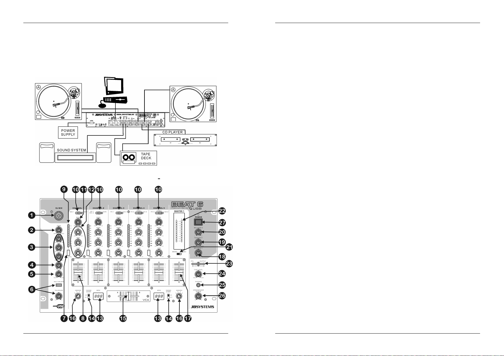
ESPAÑOL MANUAL DE INSTRUCCIONES
ESPAÑOL MANUAL DE INSTRUCCIONES
CONEXIONES
Excepto para los micrófonos, los auriculares y las salidas maestras, todas las conexiones son cinch. Utilice
cables cinch-cinch de buena calidad para evitar una mala calidad de audio. Para obtener más información
sobre las conexiones,consulte el capítulo siguiente.
Asegúrese de apagar la unidad de mezclas antes de realizar cambios en las diferentesconexiones.
En este manual hablamos de “entradas de línea”. Este es un nombre general para las entradas con un nivel
de hasta 2V.esto incluye sintonizadores,vídeos, reproductores de CD, etc.
Ambas conexiones de USB serán detectadas como una tarjeta de sonido en su ordenador. Estas
conexionesson bidireccionales(reproducción y grabaciónde música simultáneamente)
CONTROLES Y FUNCIONES (FRONTAL)
1. JACK DE ENTRADA DE MIC DE DJ: Jack Combo. Acepta tanto un micrófono balanceado con un
conector XLR o un micrófono desbalanceado con un mono jack de 1/4”. Esta entrada es utilizada
principalmente como micrófono de DJ. Al hablar no se afectael nivel de la señal de esta entrada.
2. NIVEL DE GANANCIA: Ajusta el nivel de entrada de la entrada DJ. Utilice este control para ajustar el
nivel del micrófono DJ en el medidor VU en aproximadamente 0 dB.
3. CONTROL DE TONOS DE 3 BANDAS: La frecuencia del micro DJ puede controlarse sobre un rango
de +/- 12 dB.
4. CONTROL PANPOT: Se utilizapara localizar el sonido del micro DJ en algún lugar del campo estéreo.
Un control panpot hace lo mismo para las señales mono como lo hace un control de balance para las
señales estéreo.
5. VOLUMENDEL MIC DJ: Se utiliza para ajustarel nivel del micro DJ.
6. EMISIÓN: Utilice el interruptor para silenciar automáticamente los canales de entrada 1 a 5 mientras
habla a través del micrófono DJ. Puede ajustar el gradode silenciamiento en los canales de entrada 1 a
5. Si gira más hacia la derecha el nivel, estos canales se silenciarán más mientras habla a través del
Micro (1) DJ.
7. SELECTOR PFL: Se utiliza para seleccionar la fuente (C-1 a C-5) que se va a monitorear a través de la
salida de los audífonos.Al pulsar los botones múltiples de CUE es posible obtener un sonido mezclado
desdelas fuentes seleccionadas.
8. CANAL FADER: Se utiliza para establecer el nivel de cada canal separadamente. Puede cambiar
fácilmente este fader por uno nuevo. Más adelante en este manual le explicamos como hacerlo.
9. CANAL DEL MEDIDOR VU: Cada canal tiene su propio medidor LED de VU de tal manera que puede
ajustar el nivel de ganancia (11) rápidamente. Asegúrese de que los niveles no excedan 0 dB (o 100%).
Se tiene el riesgo de que el audio se distorsione cuando el nivel de señal llegue a la zona roja del
medidor VU.
10. SELECTOR DE FUENTE DE ENTRADA: Se utiliza para seleccionar la entrada correcta en cada canal:
Phono, línea, USB, aux.o mic. En algunos canales existen selectores de entrada adicionales en la parte
trasera.
Consejo: Línea, Aux., CD, Sintonizador, etc. son nombres diferentes para las entradas con casi los
mismosniveles deseñal.
11. NIVELDE GANANCIA: Ajusta el nivel de entrada en cada canal. Utilice estecontrol para ajustar el nivel
en el medidor VU en aproximadamente0 dB.
12. CONTROLES DE TONOS DE 3 BANDAS: La frecuencia de cada canal puede controlarse
separadamente sobre un rango desde -26 dB a +12 dB. En la posición central el control de tono está
desafinado.(apagado)
13. PANTALLA CONTADORA DE BEATS: Muestra el número de beats por minuto (BPM) de la música en
el canal seleccionado con el selector de asignación de crossfader (16). Para tener un resultado
confiable en la pantalla la música debe tener un beat claro y constante.
14. INTERRUPTOR DE ACTIVACIÓN/DESACTIVACIÓN DE INICIO DE FADER: Al tener un reproductor
de CD compatible conectado en los conectores del control de fader, puede controlar las funciones de
inicio/parada (re-cue) con el cross fader. Con este interruptor puede activar o desactivar el control de
inicio de fader.
15. CROSSFADER : Con este fader de VCA puede mezclar entre los canales que seleccionó con los
selectores de asignación de crossfader (16). ¡El crossfader solamente funciona cuando mueve los
faders de canal seleccionados (8) al nivel deseado! El crossfader también integra el inicio del fader
óptico. Consulte el capítulo siguiente para obtener más información sobre esto.
16. ASIGNACIÓN DE CROSSFADER: Selecciona los canales de entrada que se van a utilizar con el
crossfader (15) y los contadores de beats (13). Cuando se establece en “0” el crossfader es
desactivado.
17. NIVELMASTER1: Se utiliza para ajustar el nivel de la salida maestra1 balanceada.
(Atención: la “salida de recorte” (43) en la parte trasera de la mezcladora puede reducir el nivel de
salida máximo del fader de salida maestro.Cheque esterecortador si el nivel de salida máximo estápor
debajo de lo normal.)
18. MASTER1 DE BALANCE: Se utiliza para ajustar el balance entre la salida izquierda y derecha en el
Master1.
19. NIVEL DEL MASTER2: Se utiliza para ajustar el nivel de la salida maestra 2 desbalanceada.
20. MASTER2 DE BALANCE: Se utiliza para ajustar el balance entre la salida izquierda y derecha en el
Master2.
21. InterruptorMONO/ESTÉREO: Se utiliza para cambiarambos maestros en el modo mono o estéreo.
22. MEDIDORES VU DEL MASTER1: Monitorea el nivel de salida del master1. Asegúrese de que los
niveles no excedan 0 dB (o 100%). Se tiene el riesgo de que el audio se distorsione cuando el nivel de
señal llegue a la zona roja del medidor VU.
JB SYSTEMS
®
33/44 BEAT6 USB
JB SYSTEMS
®
34/44 BEAT6 USB
Page 20
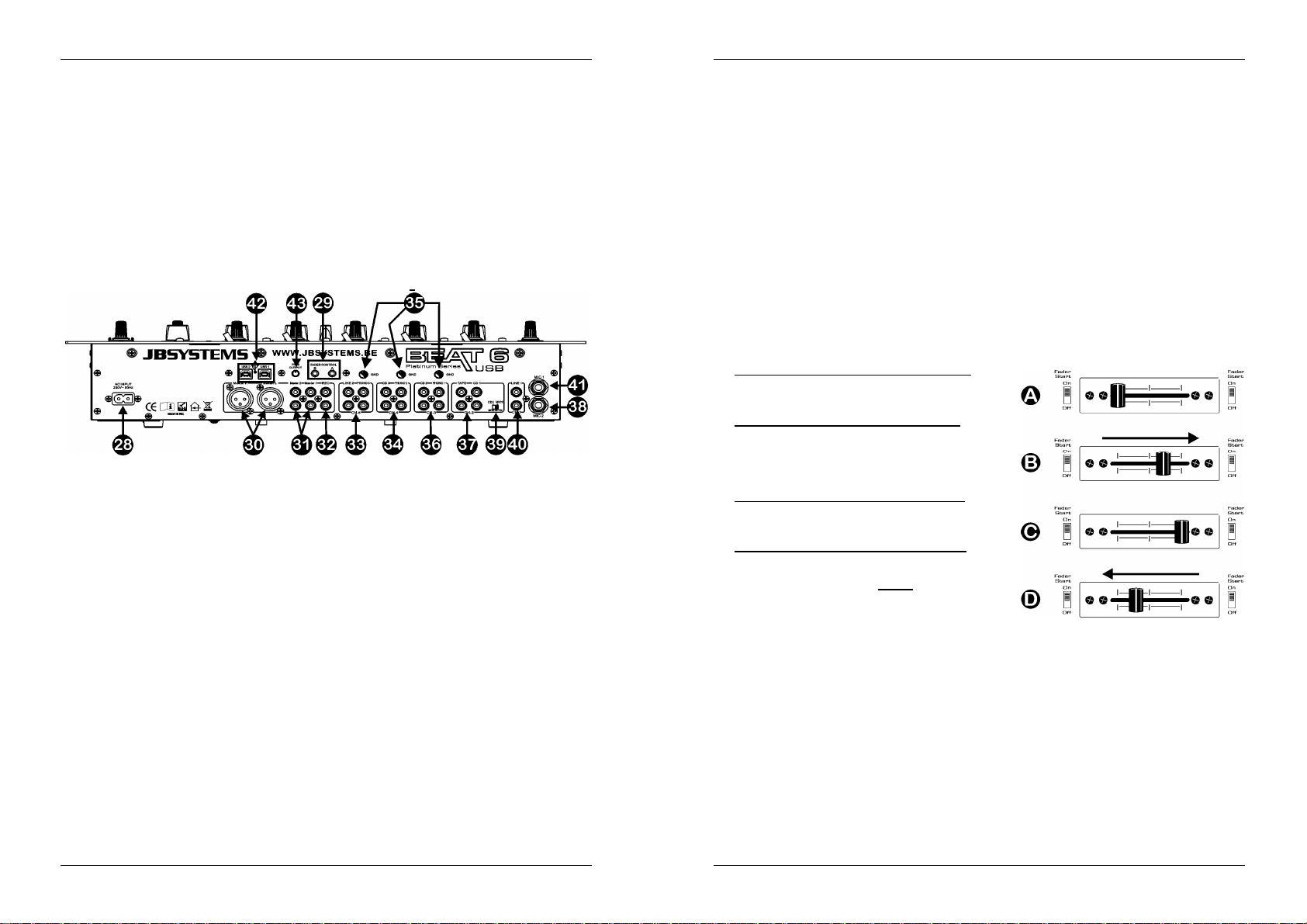
ESPAÑOL MANUAL DE INSTRUCCIONES
ESPAÑOL MANUAL DE INSTRUCCIONES
23. MEZCLA DE CUE: Con este fader puede mezclar la salida master y cualquiera de los canales de
entradaa través de la salida de audífonos(25):
Coloque el fader en la posición extrema hacia la izquierda para monitorear una señal PFL
seleccionada(7).
Coloque el faderen la posición extrema haciala derechapara escuchar la salida master.
Coloque el fader en cualquier otraposición para escuchar un mezcla de dos señales.
Esta opción le permite verificarsu mezcla antes de colocarlaen la salida master.
24. NIVEL DE CUE: Se utilizapara controlarel nivel de salida de la salida de los audífonos.
25. Jack DE LOS AUDÍFONOS: Puede monitorear todas las entradas/salidas cuando conecta cualquier
audífonoestéreo moderno en este jack de 6.3 mm.
26. CURVA DE CROSS FADER: Ajusta la curva del cross fader desde lo suave (posición izquierda) hasta
lo desafinado(posición derecha).
27. Interruptor de alimentación: Se utiliza para encender o apagar la mezcladora. El led azul se ilumina
cuando la mezcladorase enciende.
CONTROLES Y FUNCIONES (TRASERA)
28. CABLE DE ALIMENTACIÓN: conecte este cable a una toma de corriente de 230 V/50 Hz. ¡Antes de
utilizarlo,inspeccione el cable para asegurarsede que no está dañado!.
29. CONTROL DE FADER: Cuando se conecta a estas entradas, los reproductores de CD compatibles
pueden controlarse por el inicio del fader de esta mezcladora.
30. SALIDA BALANCEADA DEL MASTER1: Los conectores XLR se pueden utilizar para conectar esta
mezcladora a cualquier entrada amplificadora balanceada, utilizando cables de señal balanceada
especiales.
31. SALIDAS DESBALANCEADAS DEL MASTER: La salida “master1” tiene la mismaseñal de salida que
tiene la salida master balanceada (30) pero desbalanceada. La salida “master 2” tiene la misma señal
pero puede controlarse independientementecon el nivel/balance del master2 (19/20). Utilice las salidas
paraconectaramplificadores desbalanceados.
32. SALIDA DE GRABACIÓN: Tiene la misma señal de salida como la que tienen las salidas maestras
pero no es influenciada por el nivel maestro, balance y los controles mono/estéreo. Se utiliza para
conectar equipos de grabación analógicos. También puede conectar un ordenador para la grabación
digital directa,vea las conexiones USB (42).
33. CANAL 5 DE ENTRADA: Se utiliza para conectar dos lineas diferentes de señales de audio. También
puede conectar un ordenador a través de los conectores USB (vea 42). El selector de fuente de entrada
(10) al frente determina que entrada se activará.
34. CANAL 4 DE ENTRADA: Se utiliza para conectar una tornamesa y/o un nivel de línea de señal de
audio. También puede conectar un ordenador a través de los conectores USB (vea 42). El selector de
fuente de entrada (10) al frente determinaque entrada se activará.
35. CONEXIÓN A TIERRA (GND): Muchas tornamesas tienen una conexión GND. Es preferible conectar
esta señal de tierra al conector GND. Si su tornamesa no cuenta con un cable de conexión a tierra, no
tiene que utilizar este conector.
36. CANAL 3 DE ENTRADA: Se utiliza para conectar una tornamesa y/o un nivel de línea de señal de
audio. El selectorde fuente de entrada (10) al frente determinaque entrada se activará.
37. CANAL 2 DE ENTRADA: Se utiliza para conectar dos lineas diferentes de señales de audio. Consulte
Interruptor (39) para cambiar una entrada de línea al nivel del micrófono. El selector de fuente de
entrada(10) al frente determinaque entradase activará.
38. ENTRADA DE MIC2: Se utiliza para conectar un micrófono balanceado al canal 2. Consulte Interruptor
(39) paracambiar la entradade CD1 a mic2.
39. INTERRUPTOR MIC2/CD1: Este interruptor hace posible cambiar entre la entrada de CD1 (37) y la
entradade mic2 (38) en canal 2.
40. CANAL1 DE ENTRADA DE LÍNEA: Se utiliza para conectar una señal de audio de nivel de línea al
canal 1.
41. CANAL1 DE ENTRADA DE MIC1: Se utiliza para conectarun micrófonoal canal 1.
42. CONEXIONES USB: dos conexiones USB bidireccionales (USB1 para C4 ~ USB2 para C5). Puede
conectar cualquier ordenador a través de estas conexiones USB. El PC/Mac detectará su mezcladora
como una tarjeta de sonido, normalmente no se necesitan controladores. ¡Debido a que ambos puertos
USB son bidireccionales puede reproducir música en su ordenador y mezclarla con otras fuentes como
CD, phono, etc. Al mismo tiempo puede grabar su mezcla en su ordenador con la misma conexión
USB!.
43. RECORTADOR DE SALIDA: Este potenciómetro se utiliza para reducir el nivel de salida de la
mezcladora para proteger los amplificadores conectados y los gabinetes del altavoz. (Atención: el nivel
de salida puede reducirse a cero. Si no tiene ninguna señal en la salida master, primero verifique si el
potenciómetrofue puesto accidentalmente en cero).
INICIO DE CROSSFADER
El crossfader integra los interruptores de inicio de fader óptico. Estos faders con compatibles con todos los
reproductoresde CD actuales de JB Systems. Funciona de este modo:
E. CROSSFADER EN LAPOSICIÓNIZQUIERDA:
El reproductor de CD conectado al conectorde inicio de
fader A se encuentra reproduciendo, el otroreproductor
en pausa.
F. CROSSFADERSE MUEVEA LADERECHA:
El reproductor de CD conectado al conector de inicio de
fader A detienela reproducción, regresa al punto de cue
programado previamente y espera en pausa. El otro
reproductor de CD empieza a reproducir desde el punto
cue programado previamente.
G. CROSSFADER EN LA POSICIÓNDERECHA:
El reproductor de CD conectado al conector de inicio de
fader B se encuentrareproduciendo, el otro reproductor
en pausa.
H. CROSSFADER SE MUEVE A LA IZQUIERDA:
El reproductor de CD conectado al conector de inicio de
fader B detienela reproducción, regresa al punto de cue
programado previamente y espera en pausa. El otro
reproductor de CD empiezaa reproducir desde el punto
cue programado previamente.
Importante:¡Ambos interruptores de fader deben estar en la posición “ON”!
JB SYSTEMS
®
35/44 BEAT6 USB
JB SYSTEMS
®
36/44 BEAT6 USB
Page 21

ESPAÑOL MANUAL DE INSTRUCCIONES
CAMBIO DE LOS FADERS
Una de las grandes ventajas de esta mezcladoraes la posibilidad de cambiar los faders de canal
Tiene que llevar a cabo lo siguiente para cambiar un fader
de canal:
Retire los botones del fader.
Retire los 8 tornillos que sostienen el pequeño panel frontal
alrededorde los faders.
Retire los 3 tornillosdel fader que desea cambiar.
Con cuidado retire el fader de su posición y desconecte el
conectordel tablero principal. (¡No tire del cable!)
Coloque el nuevo fader con cuidado en su lugar. Asegúrese
de conectar los conectores en la base del conector en la
tarjetaPCB de la mezcladora.
Coloque los 3 tornillos del faderotravez en su lugar
Coloque la pequeña placa delantera en su lugar con los 8
tornillos.
¡Ya está!
Tieneque llevar a cabo lo siguiente para cambiar el cross fader:
Retire el botón del fader del cross fader.
Retire los 2 tornillos que sostienen el cross fader en su lugar.
Con cuidado retire el fader y la placa de la cubierta de sus posiciones.
Desconecteel cross fader del cable (¡desconecte el cable tirando del conector, NO del cable!)
Presione el nuevo cross fader en el cable.
Coloque el cross fader de regreso en su lugar con la pequeñaplaca de cubierta y los 2 tornillos.
¡Ya está!
ESPECIFICACIONES
Suministro de alimentación: CA230V, 50 Hz (34 watss)
Respuesta defrecuencia: 20-20.000 Hz (+/-3 dB)
THD + ruido: <0.05% @ 1 kHz, 0 dB, carga = 47 kΩ
Relación S/N (IHF-A): >78 dB @ 1 kHz.
ConexionesUSB: USB2.0, bidireccional(44,1 kHz / 16 bit)
USB cable (no incluido): L
Entradas de Micro: 2 mV @ 3kΩ
Entradas de Línea/CD: 340 mV@ 47 kΩ
Entradas de Phono: 3 mV @ 47 kΩ
Salida de grabación: 775 mV @ 1 kΩ
SalidaMaster 1/2: 1.55 V @ 1 kΩ desbal.
SalidaMaster 1: 2,55 V @ 600Ω bal.
Emisión: 0dB -14dB
Controles de tonode canal: +12dB / -26dB (70 Hz,1 kHz, 13 kHz)
Controles de tonodel Micro DJ: +12dB / -12dB (70 Hz, 1 kHz, 13 kHz)
Audífonos: 3V@32Ω
Dimensiones: 483(A)x 310(P) x 112(A) mm (19”/7U)
Peso: 6,9kg
Windows®& MacOS®compatible.
= 3m
max
PORTUGUÊS MANUAL DO UTILIZADOR
Obrigado por ter adquirido este produto da JB Systems®. De modo a tirar total proveito das possibilidades
deste produto, por favor leia este manual com atenção.
CARACTERÍSTICAS
Esta unidade está protegida contra interferênciasrádio. Este produto cumpre as exigências impostas pelas
presentes directivas nacionais e europeias. A conformidadedeste produto foi comprovada e as declarações
e documentos relevantes foram efectuadospelo fabricante.
14 entradasem 6 canais (6 line, 3 phono, 2 USB,3 microfones)
2 ligações USB bidireccionais(reprodução e gravação ao mesmotempo!)
1 microDJ balanceadoseparadocom talkover
Controlosganho (Gain), agudos (High), médios (Mid) e baixos (Low) em todos os canais
Possibilidade de atribuir e substituir facilmenteo crossfader
DJ faders “steel rail” de alta qualidade
2 saídas Master,com controlode balançoindividual
Master1 com saídas XLR balanceadas e sinal extra
Indicadoresde LEDS VU-METERSnos canais de entrada e master 1
Contadoresde batida automáticosde alta precisão
Função crossfader start paraleitoresde CD compatíveis
AudiçãoPré-fadecom opção cue mix
ANTES DE UTILIZAR
Antes de utilizar esta unidade verifique se existem danos provocados durante o transporte. Caso existam
danos aparentes,não utilize a unidade e contacteo seu revendedor.
Importante:
imprescindível que o utilizador siga as instruções de segurança e avisos descritos neste manual.
Quaisquer danos provocados por utilização incorrecta não serão cobertos pela garantia. O revendedor
não será responsável por quaisquer danos ou problemas causados pelo incumprimento das instruções
deste manual.
Guarde este manual num local seguro para consulta futura. Caso venda esta unidade, forneça este
manual.
Verifique o conteúdo:
Certifique-seque a caixacontém os seguintes artigos:
Mesade mistura BEAT6 Mk2
Manualdeinstruções
Cabo de alimentação
Esta unidade deixou a nossa fábrica em perfeitas condições e devidamente embalada. É
INSTRUÇÕES DE SEGURANÇA:
ATENÇÃO: De forma a evitar o risco de choque eléctrico,
CAUTION
não remova peças da unidade. Não tente fazer reparações.
Contactepessoal qualificado.
Puede descargar la última versión de este manualde usuario en nuestra página Web:
JB SYSTEMS
Toda la información está sujeta a cambios sin previo aviso
www.beglec.com
®
37/44 BEAT6 USB
O símbolo composto por um triângulo equilátero com um relâmpago no interior alerta para a
presença de voltagem perigosa não isolada no interior do produto que poderá constituir risco de
choque eléctrico.
O símbolo composto por um triângulo equilátero com um ponto de exclamação alerta o utilizador
paraa presença de instruções importantesde utilização emanutenção do produto.
Este símbolo significa: utilização unicamente em espaços fechados.
JB SYSTEMS 38/44 BEAT6 USB
Page 22
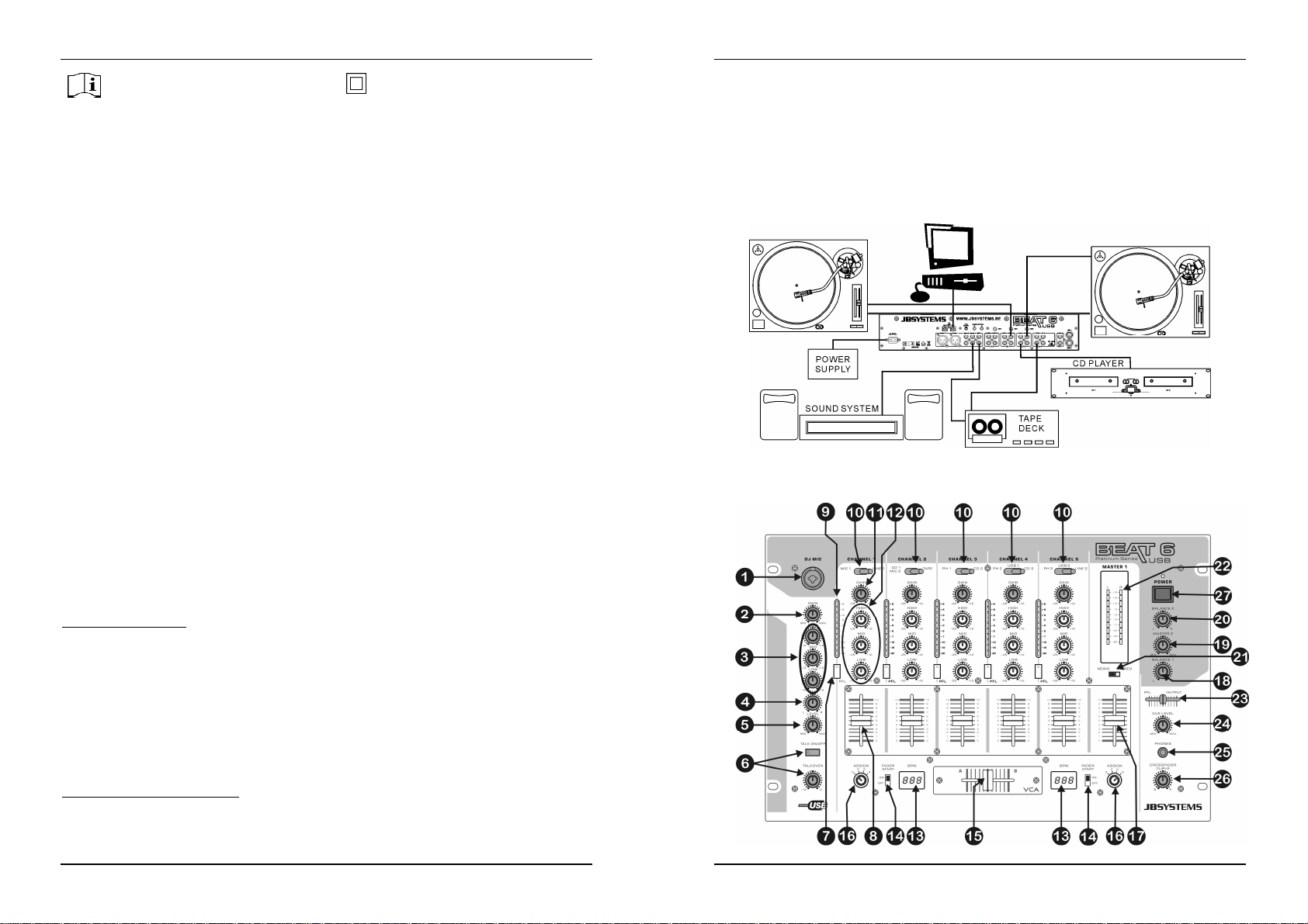
PORTUGUÊS MANUAL DO UTILIZADOR
PORTUGUÊS MANUAL DO UTILIZADOR
De modo a evitar riscode fogo ou choque eléctrico, não exponha este produto a chuva ou humidade.
De forma a evitar a formação de condensação no interior da unidade, ao transportá-la para ambiente
Estaunidade destina-se unicamente a utilização em espaçosfechados.
Não introduza objectos de metal nem verta líquidos no interior do produto, correrá risco de choque
Não coloque chamas descobertas(tais como velas acesas) sobre a unidade.
Não cubra os orifíciosde ventilação ou a unidade poderá sobreaquecer.
Evitelocais com poeiras.Limpe a unidade regularmente.
Mantenha esta unidade fora do alcance dascrianças.
Esta unidade deverá ser operadaunicamente por pessoas experientes.
Temperatura ambiente de funcionamento máxima é de 40ºC. Não utilize esta unidade a temperaturas
As distâncias mínimas para a ventilação suficiente são 5 cm.
Desligue sempre a unidade da correntequando não a utilizar durante longos períodos de tempo ou antes
A instalação eléctrica deve ser efectuadaunicamente por pessoal qualificado,cumprindo os regulamentos
Certifique-seque a voltagem a utilizar não é superior à voltagem indicada no painel traseiroda unidade.
A tomada de correntedeverá permaneceracessível para que a unidade possa ser desligada da corrente.
O cabo de alimentação deverá estar sempre em perfeitas condições. Desligue a unidade e substitua
Nunca permita que este cabo entre em contactocom outros cabos!
De modo a evitar um acidente, a unidade deverá ser usada apenas com o adaptador AC fornecido com
Quando o interruptor de poder está na posição de repouso, esta unidade não está desconectada
De formaa não correr risco de choque eléctrico não abra a cobertura da unidade. À excepção do fusível,
Em caso de problemas sérios de funcionamento, interrompa a utilização da unidade e contacte
Caso seja necessáriotransportara unidade utilize a embalagemoriginal.
Pormotivosde segurança, são proibidas quaisquer alteraçõesnão autorizadasà unidade.
GUIA DE INSTALAÇÃO:
Instale a unidade num local bem ventilado onde não estejaexpostaa altas temperaturasou humidade.
Colocar ou utilizar a unidade durante longos períodos de tempo perto de fontes de calor, tais como
A unidade pode ser montada numa rack de 19 polegadas. Fixea unidade utilizando os orifícios existentes
Quando colocar a unidade numa cabine ou numa flight case, certifique-se que há ventilação de modo a
De forma a evitar a formação de condensação no interior da unidade, ao transportá-la para ambiente
LIMPEZADA MESA DE MISTURA:
Utilize um pano limpo ligeiramente humedecido em água. Evite introduzir água dentro da unidade. Não
utilizelíquidos voláteis como benzeno ou diluente, irá danificar a unidade.
Estesímbolosignifica:Leia instruções.
quente aguarde algum tempo de modo a que haja uma ambientação à temperatura. A condensação
poderá afectaro desempenho da unidade ou até danificá-la.
eléctrico ou poderá danificar o produto. Caso algum objecto estranho entre em contacto com o interior da
unidade,desligue-a de imediato da corrente.
ambientesmais elevadas.
de efectuar manutenção.
desegurançaem instalaçõeseléctricas e mecânicas do seu país.
imediatamente o cabo caso este apresente algum dano. Deverá ser substituído pelo fabricante, pelo
agenteautorizado ou pessoal qualificado de modo a evitar um acidente.
ela. Se oadaptador estiver danificado, apenas poderá ser usado outro adaptador do mesmo modelo.
completamente dos canos principais!
nãoexistempeças que possam ser substituídas pelo utilizador.
Nunca
repareum fusívelnem tente operara unidade sem fusível. Substitua
por outro com as mesmas características!
imediatamente o seu revendedor.
amplificadores, holofotes, etc, irá afectar o desempenho da unidade e poderá até danificá-la.
no painel frontal. Certifique-se que utiliza parafusos com a medida certa (os parafusos não são
fornecidos).Evite pancadas e vibraçõesdurante o transporte.
permitira evacuação do calor produzidopela unidade.
quente aguarde algum tempo de modo a que haja uma ambientação à temperatura. A condensação
poderá afectaro desempenho da unidade.
Este símbolo significa: Aparelho Classe II
sempre
umfusível danificado
LIGAÇÕES
À excepção das saídas dos microfones,do auscultador e a master, todas as ligações são rca. Utilizecabos
rca-rca de boa qualidade de modo a evitarmá qualidadeáudio.
Para mais informações sobre ligações consulte o próximocapitulo.
Certifique-seque a mesa de mistura se encontra desligada antes efectuar alterações nas ligações.
Neste manual referimos “line inputs” (entradas line). Esta é uma denominação global para aparelhos de
entrada com um nível de voltagem compreendido até 2V. Isto inclui sintonizadores, vídeos, leitores de CD,
etc.
Ambas as ligações USB serão detectadas como placas de som no seu computador. Estas ligações são
bidireccionais(reproduzem e gravam simultaneamente)
CONTROLOS E FUNÇÕES (FRONTAL)
JB SYSTEMS 39/44 BEAT6 USB
JB SYSTEMS 40/44 BEAT6 USB
Page 23
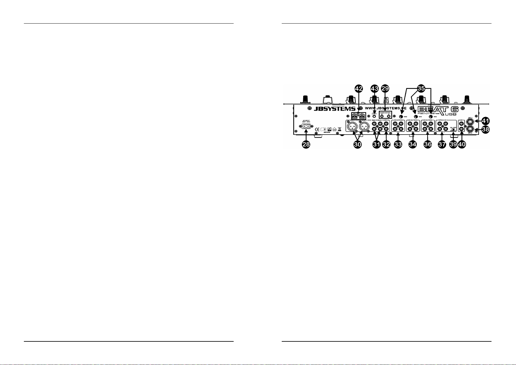
PORTUGUÊS MANUAL DO UTILIZADOR
PORTUGUÊS MANUAL DO UTILIZADOR
1. ENTRADA MICROFONE DJ (JACK): Combo jack. Aceita microfones balanceados com conector XLR
bem como microfones mono sem balanço tipo jack ¼”. Esta entrada é geralmente utilizada para
microfoneDJ. A função talkover não afectao nível de sinal desta entrada.
2. CONTROLO DE GANHO (GAIN): Este controlo dá a possibilidade de ajustar o nível da entrada DJ.
Utilizeeste controlo para ajustar o nível do microfoneDJ no indicador VUa cercade “0 DB”.
3. CONTROLODE TOM DE 3 BANDAS: A frequência do microfone DJ pode ser controlada numa escala
de +/-12DB.
4. CONTROLOPANPOT: Permite colocar o som proveniente do microfone DJ alguresno campo estéreo.
O controlo panpot funciona para os sinais mono como o balance funciona para os sinais estéreo.
5. NÍVEL DJ MIC: Permite ajustar o nível do microfone DJ.
6. TALKOVER: Quando pressiona este botão, os canais de entrada 1 a 5 são silenciados enquanto fala
através do microfone DJ. Pode ajustar o nível de supressão de som nos canais de entrada 1 a 5.
Quanto mais girar o controlo talkover para a direita, maior será a supressão de som nos canais
enquanto fala através do microfone DJ (1).
7. SELECTORES PFL: Estes selectores permitem monitorizar através dos auscultadores o canal
escolhido (CH1 a CH5). Se pressionar vários botões PFL poderá ouvir o som misturado das fontes
seleccionadas.
8. FADER DO CANAL: Permite determinar o nível de cada canal separadamente. Pode facilmente
subsituir este fader por um novo. Mais á frente neste manual iremos explicarcomo fazer isto.
9. VU-METER DE CANAL: Cada canal tem um indicador VU de LEDs que permite ajustar o nível de
ganho (11) muito rapidamente. Certifique-se que os níveis não excedem 0 DB(ou 100%). O som poderá
sofrer distorçãose o nível do sinal alcançara área vermelhado indicador.
10. SELECTORES DE ENTRADA: Estes selectores permitem seleccionar a origem de som para cada
canal: Phono, line, USB, aux. ou mic. Existem selectores adicionais para alguns canais no painel
traseiro.
Nota: line,aux.,CD, tuner, etc, são diferentes nomes para entradas com quase o mesmotipo de sinal.
11. CONTROLODE GANHO (GAIN): Este controlo dá a possibilidadede ajustar o nível de entrada de cada
canal. Utilize este controlopara ajustar o nível no indicadorVU a cerca de “0 DB”.
12. CONTROLO DE FREQUÊNCIA DE 3 BANDAS: A frequência de cada canal pode ser controlada
separadamente, Permitindo corrigir o sinal numa escala de –26DB a +12DB. Na posição central o
controlode frequência encontra-sedesligado.
13. INDICADOR DE BATIDAS: Este indicador mostra as batidas por minuto (BPM) do canal seleccionado
com o selector de crossfader (16). Irá obter um resultado mais exacto se a música tiver uma batida
nítida e estável.
14. INTERRUPTOR FADER START ON/OFF: Após ter um leitor de CD compatível ligado aos conectores
do faderstart, pode controlar as suas funções start/stop (re-cue) através do crossfader. Com este botão
pode ligar e desligar o controlo fader start.
15. CROSSFADER: Permite a passagem gradual do canal atribuído ao lado esquerdo do VCA crossfader
para o canal atribuído ao lado direito e vice-versa (16). Esta função só resulta quando tiverseleccionado
o nível que pretende em cada canal com os faders dos canais (8)! O crossfader também integra a
função optical fader start. Consulte mais informação sobre estafunção no próximo capítulo.
16. SELECTOR DE CROSSFADER: Permite seleccionar os canais de entrada a utilizar com o crossfader
(15) e com os indicadores de batidas (13). Quando este selector se encontra na posição “0”, o
crossfaderestádesligado.
17. NÍVELMASTER1: Permiteajustar o nível da saída balanceadamaster1
(Atenção: O controlo “Trim Output” (43) situado na parte de trás da mesa de mistura pode reduzir o
nível máximo de saída do fader da saída master. Verifique este controlo caso o nível de saída máximo
esteja abaixo do normal.
18. BALANCE MASTER1: Permiteajustar o balanço entre a saída à esquerda e à direita na saída master1.
19. NÍVELMASTER2: Permiteajustar o nível da saída sem balanço master2.
20. BALANCE MASTER2: Permiteajustar o balanço entre a saída à esquerda e à direita na saída master2.
21. INTERRUPTOR MONO/STEREO: Permite alternar os dois masters entre modo mono ou estéreo.
22. LEDS INDICADORES VU MASTER1: Indica o nível de saída da saída master1. Certifique-se que os
níveis não excedem 0DB (ou 100%). O som poderá sofrer distorção quando o nível do sinal alcança a
área vermelha do indicador.
23. CUE MIX: Permite misturar a saída master e qualquer um dos canais de entrada através dos
auscultadores(25):
Desloque o fader totalmentepara a esquerda para monitorizar o sinal PFL seleccionado (7).
Desloque o fader totalmentepara a direita para monitorizar a saída master.
Coloqueo fader em qualquer outra posição para ouvir uma mistura dos dois sinais.
Esta opção permiteverificar a mistura antes de a passar para a saída master.
24. NÍVELCUE: Permite controlar o nível da saída dos auscultadores.
25. ENTRADA AUSCULTADORES (PHONES): Entrada tipo jack para auscultadores estéreo (diâmetro
6.35mm).
26. CROSS FADER CURVE: Permite ajustar a curva do crossfader entre suave (posição à esquerda) e
rápida (posição à direita).
27. INTERRUPTOR ON/OFF: Liga e desliga a mesa de mistura. O Led azul permanece aceso quando a
mesa de mistura está ligada.
CONTROLOS E FUNÇÕES (TRASEIRO)
28. CABO ALIMENTAÇÃO: Ligue este cabo a uma tomada de 230V / 50Hz. Antes da utilização certifiquese de que o cabo não está danificado!
29. FADER CONTROL: Quando ligados a estas entradas, os leitores de CD compatíveis podem ser
controladosatravés da funçãofader start desta mesa de mistura.
30. SAÍDA MASTER1 BALANCEADA: Os conectores XLR podem ser utilizados para ligar esta mesa de
mistura à entrada balanceadade um amplificador,através de cabosespeciais de sinal balanceado.
31. SAÍDAS MASTER SEM BALANÇO: A saída “master 1” não tem balanço mas tem o mesmo sinal de
saída que a saída master balanceada (30). A saída “master 2” transporta o mesmo sinal mas pode ser
controlada individualmente pelo nível/balanço do master2 (19/20). Use as saídas para ligar
amplificadores sem balanço.
32. SAÍDA PARAGRAVAÇÃO (REC): Esta saída transporta o mesmosinal que as saídas master mas não
é influenciadapelos controlos de nível, balanço, e mono / estéreo da saída master. Destina-se à ligação
de equipamento analógico de gravação. Também pode conectar um computador para gravação digital
directa,ver ligações USB (42).
33. CANAL DE ENTRADA 5 (CH5): Permite a ligação de dois sinais diferentes de áudio do tipo line.
Também pode conectar um computador para gravação digital directa,ver ligações USB (42). O selector
de entrada (10) no painel frontal determina qual das entradas estará activa.
34. CANAL DE ENTRADA 4 (CH4): Permite a ligação de um gira-discos e / ou um sinal de áudio do tipo
line. Também pode conectar um computador para gravação digital directa, ver ligações USB (42). O
selectorde entrada (10) no painel frontaldeterminaqual das entradas estará activa.
35. LIGAÇÃO TERRA (GND): A maioria dos gira-discos tem uma ligação terra. É preferível que ligue esse
sinal a este conector terra. Se o seu gira-discos não tem esta ligação não necessita de usar este
conector.
36. CANAL DE ENTRADA 3 (CH3): Permite a ligação de um gira-discos e / ou um sinal de áudio do tipo
line. O selectorde entrada (10) no painel frontal determina qual das entradas estará activa.
37. CANAL DE ENTRADA 2 (CH2): Permite a ligação de dois sinais diferentes de áudio do tipo line. Utilize
o interruptor (39) para alterar uma entrada line para microfone. O selector de entrada (10) no painel
frontaldeterminaqual das entradas estará activa.
38. ENTRADA MIC2: Permite ligar um microfone balanceado ao canal 2. Utilize o interruptor (39) para
alterara entrada CD1 para MIC2.
39. INTERRUPTOR MIC2/CD1: Este interruptor permite alternar entre entrada CD1 (37) e entrada MIC2
(38) no canal 2.
40. ENTRADA LINE CANAL1 (CH1): Permiteligar umsinal áudio de tipo line ao canal 1.
41. ENTRADA MIC1 CANAL1 (CH1): Permite ligar um microfone ao canal 1.
42. LIGAÇÕES USB: 2 ligações USB bidireccionais (USB1 para CH4 ~ USB2 para CH5). Pode conectar
qualquer PC através destas ligações USB. O PC/Mac irá detectar a vossa mesa de mistura como placa
JB SYSTEMS 41/44 BEAT6 USB
JB SYSTEMS 42/44 BEAT6 USB
Page 24
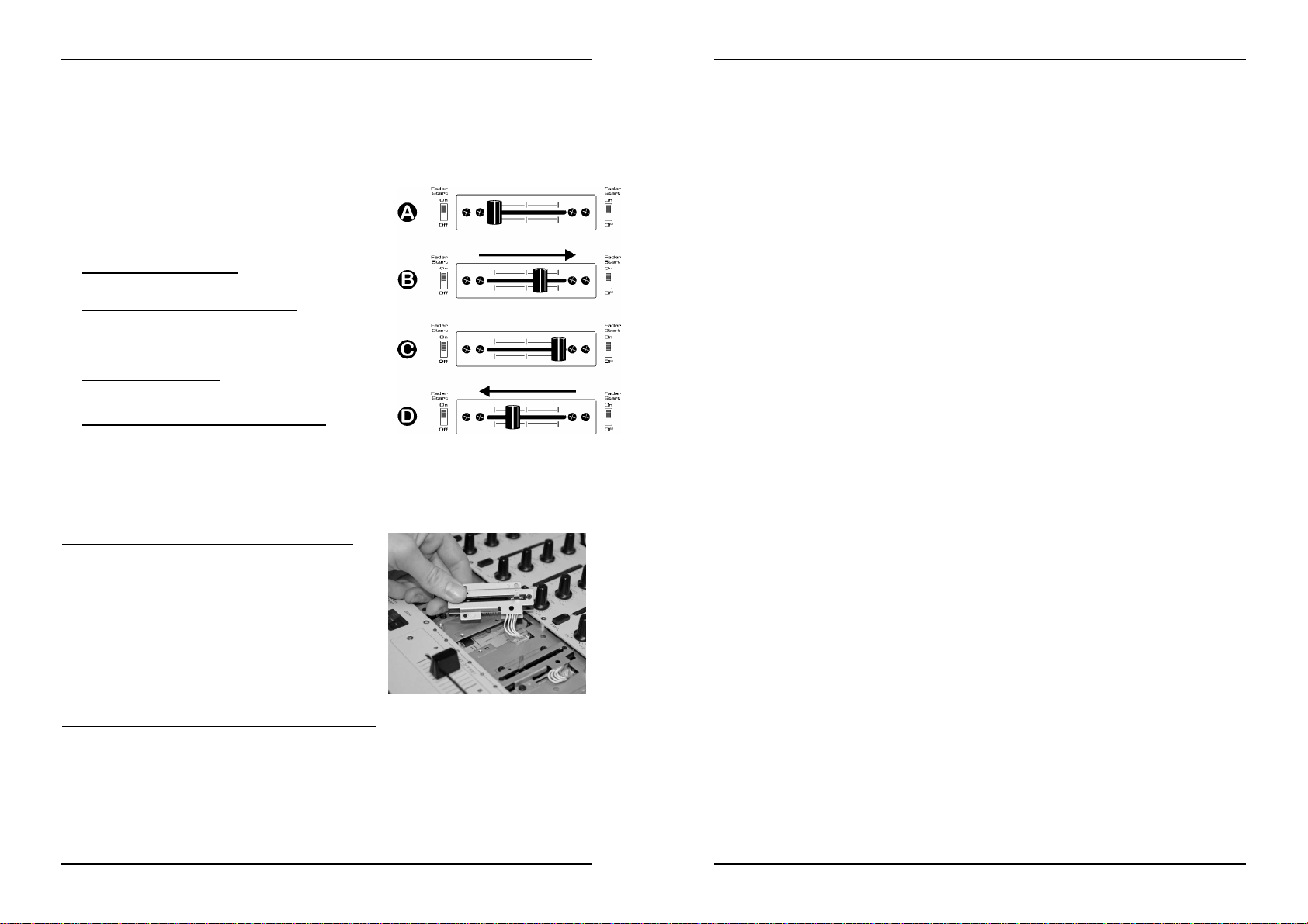
PORTUGUÊS MANUAL DO UTILIZADOR
PORTUGUÊS MANUAL DO UTILIZADOR
de som, normalmente não serão necessários drivers. Dado que ambas as portas USB são
bidireccionais poderá reproduzir música no seu PC e misturar estamúsica com outras fontes como CD,
gira discos, etc. Ao mesmo tempo pode gravar a sua mistura no seu computador com a mesma ligação
USB!
43. TRIM OUTPUT: Este potenciómetro é utilizado para reduzir o nível de saída da mesa de mistura de
forma a proteger os amplificadores e colunas que estejam ligados. (Atenção: o nível de saída pode ser
reduzido a zero. Caso não tenha qualquer sinal na saída Master, comece por verificar se este controlo
não está definido para zero.)
CROSSFADER STARTS
O crossfader integra os interruptoresoptical start. Estes fader
starts são compatíveis com todos os leitores de CD da JB
Systems. O modo de funcionamento é o seguinte:
A. CROSSFADER ÀESQUERDA:
O leitor de CD ligado ao conector fader start A está a
reproduzir,o outro o leitor de CD está em pausa.
B. CROSSFADER MOVE-SEPARA DIREITA:
O leitor de CD ligado ao conector fader start A pára, volta ao
ponto cue programado anteriormente e aguarda em pausa. O
outro leitor de CD começa a reproduzir a partir do ponto cue
programado anteriormente.
C. CROSSFADER À DIREITA:
O leitor de CD ligado ao conector fader start B está a
reproduzir, o outro o leitor de CD está em pausa.
D. CROSSFADER MOVE-SEPARA A ESQUERDA:
O leitor de CD ligado ao conector fader start B pára, volta ao
pontocue programado anteriormente e aguarda em pausa. O outro leitor de CD começa a reproduzir a
partir do ponto cue programado anteriormente.
Importante: Ambos interruptoresfader start deverão estar ligados (ON)!
SUBSTITUIÇÃO DOS FADERS
Uma das grandes vantagens desta mesa de mistura é a possibilidade de substituir os faders dos canais.
Isto é o que tem de fazer para mudar umfader de canal:
Remova os botões dos faders de canal.
Remova os 8 parafusos que fixam o pequeno painel frontal
em volta dos faders.
Remova os 3 parafusos do fader que deseja trocar.
Remova suavemente o fader da sua posição e desligue o
conectorda placa principal. (NÃO puxe o cabo!)
Coloque o novo fader no lugar. Certifique-se de ligar o
conectorna base do conector na placa da mesa de mistura.
Coloque os 3 parafusosdo fader de volta no lugar.
Coloque o pequeno painel frontal de volta no lugar com os
8 parafusos.
Feito!
O que tem de fazer para substituiro crossfader é o seguinte:
Retire o cursor do crossfader.
Retire os 2 parafusos que fixamo crossfader.
Retire com cuidado o painel frontal e o crossfader do encaixe.
Desligue o crossfader do cabo (Desligue o cabo puxando o conector, NÃO o cabo!)
Ligue o novo crossfader ao cabo.
Volte a colocar o crossfaderno encaixe, aplique o painel frontale fixe com os dois parafusos.
A operação está terminada!
ESPECIFICAÇÕES
Fonte de Alimentação: AC230 V, 50Hz (34Watt)
Resposta em Frequência: 20-20.000Hz(+/-3dB)
THD + noise: <0.05% @1kHz, 0dB, carga = 47 kΩ
S/N Ratio (IHF-A): >78dB @ 1kHz.
LigaçõesUSB: USB 2.0 bidireccional (44,1kHz/16bit)
USBcabo (nao incluído): L
Entradas micro: 2mV @ 3kΩ
EntradasLine/CD: 340mV @ 47kΩ
Entradas Phono: 3mV@ 47kΩ
Saídade Gravação: 775mV@ 1kΩ
SaídaMaster 1/2: 1.55V@ 1kΩ s/balanço
SaídaMaster 1: 2,55V@ 600Ω balanceada
Talkover: 0dB -14dB
Controlo de Frequência Canal : +12dB/ -26dB(70Hz, 1kHz,13kHz)
Controlo de Frequência micro DJ: +12dB / -26dB (70Hz, 1kHz, 13kHz)
Auscultadores: 3V@32Ω
Dimensões: 483(L) x 310(A)x 112(D) mm (19”/7U)
Peso: 6,9kg
Podefazer download da versão mais recente deste manual no nosso site: www.beglec.com
Estas informações estão sujeitas a alterações sem avisoprévio
CompatívelWindows®& MacOS
= 3m
max
®
JB SYSTEMS 43/44 BEAT6 USB
JB SYSTEMS 44/44 BEAT6 USB
 Loading...