

Page 1
=Power Connections
The unit is supplied with a power plug appropriate to its voltage and destination.
Should any other connections be required they must be carried out with the following.
Power AC 120V~60Hz AC 230/240/250V~50/60Hz
Earth Green cable Green/Yellow cable
Neutral White cable Blue cable
Architectural Lighting
Professional Lighting Technology
Live Black cable Brown cable
Technical Specifications
Power AC 120V~60Hz AC 230/240/250V~50/60Hz
Breaker 10A(AK-250)/7A(AK-150)
Lamps MSD 250/2(AK-250) / CDM-T150(AK-150)
Dimension
Weight 25 kg / 55 lbs (AK-250) / 9.6 kg / 21.3 lbs(AK-150)
380mm x 240mm x 460mm / 15in x 9.5in x 18.2in(AK-250)
333mm x 200mm x 330mm / 13.2in x 7.9in x13in (AK-150)
WWW.JBSYSTEMS.BE
AKI COLOR
User Guide
Please read these instructions carefully before use
Page 2
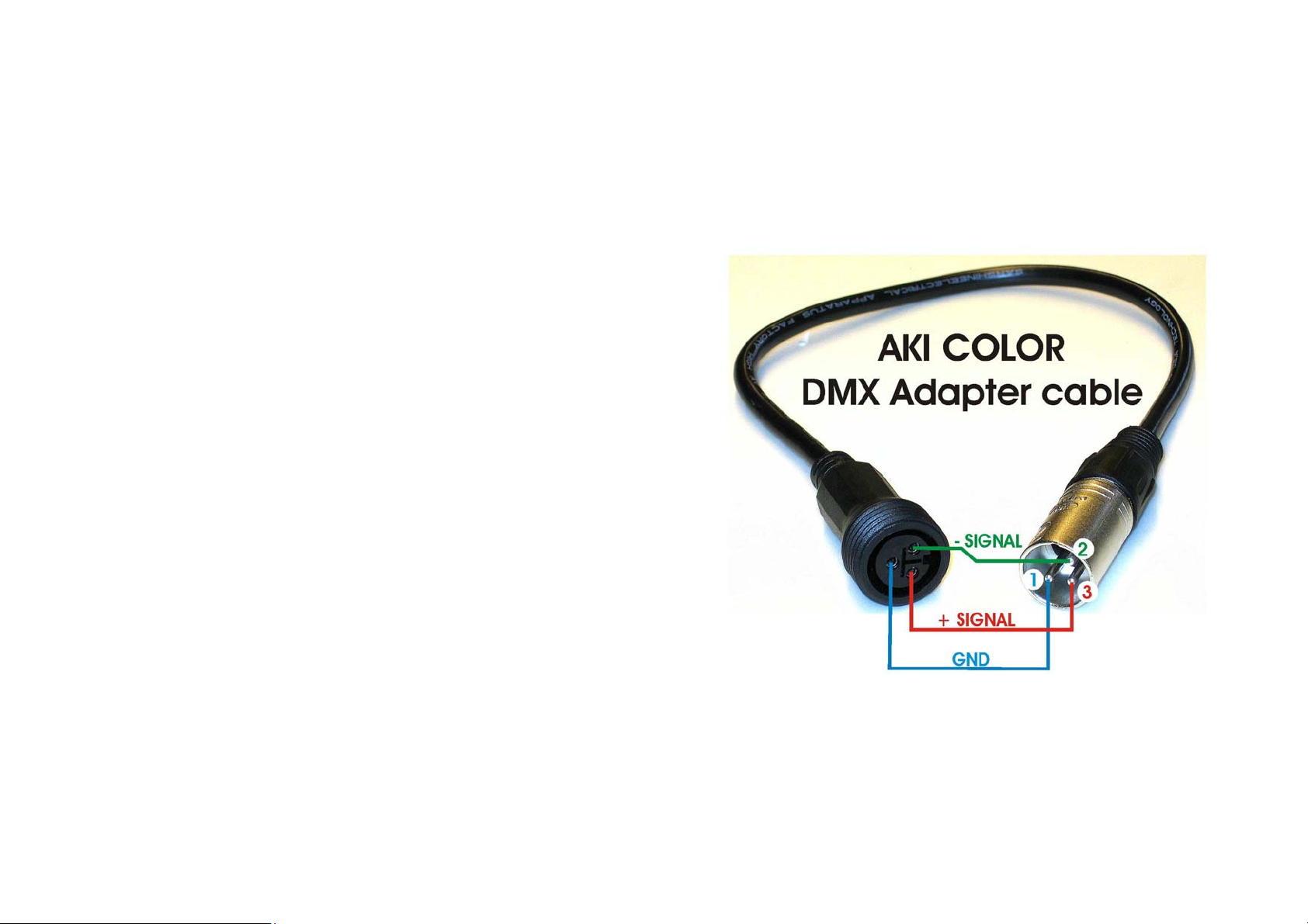
2D
Transition cable from the IP44 connector to a standard DMX-cable
TABLE OF CONTENTS
1. Safety Instruction
2. Technical Specification
3. How To Install The Unit
3.1 Lamp
3.2 How To Install The Unit On The Floor
4. How To Set The Unit
4.1 Control Panel
4.2 Main Function
5. How To Control The Unit
5.1 By master/slave preprogrammed function
5.2 By Akicolor Processor (AK-1) controller
5.3 By universal DMX Controller
5.4 DMX512 Configuration
5.5 DMX512 Connection
6. Troubleshooting
7. Fixture Cleaning
Page 3
7. Fixture Cleaning
The cleaning of internal and external optical lenses and/or mirrors must be carried out
periodically to optimize light output. Cleaning frequency depends on the environment in which
the fixture operates: damp, smoky or particularly dirty surrounding can cause greater
accumulation of dirt on the unit’s optics.
y Clean with soft cloth using normal glass cleaning fluid.
y Always dry the parts carefully.
y Clean the external optics at least every 20 days. Clean the internal optics at least every
30/60 days.
EC Declaration of Conformity
We declare that our products (lighting equipments) comply with the following
specification and bears CE mark in accordance with the provision of the
Electromagnetic Compatibility (EMC) Directive 89/336/EEC.
EN55014-2: 1997 A1:2001, EN61000-4-2: 1995; EN61000-4-3:2002;
EN61000-4-4: 1995; EN61000-4-5: 1995, EN61000-4-6:1996,
EN61000-4-11: 1994.
&
Harmonized Standard
EN60598-1: 2000+ALL:2000+A12:2002
Safety of household and similar electrical appliances
Part 1 : General requirements
1. Safety Instruction
Please read carefully the instruction, which includes important
WARNING
z Please keep this User Guide for future consultation. If you sell the unit to another user,
be sure that they also receive this instruction booklet.
z Unpack and check carefully there is no transportation damage before using the unit.
z Before operating, ensure that the voltage and frequency of power supply match the
power requirements of the unit.
z The unit is designed for use with the MSD250W or CDM-T150W. Do not use any other
type of lamp.
z It’s important to ground the yellow/green conductor to earth in order to avoid electric
shock.
z The unit must be installed in a location with adequate ventilation, at least 100 cm from
adjacent surfaces. Be sure that no ventilation slots are blocked.
z Disconnect main power before fuse/lamp replacement or servicing.
3D
z Replace fuse/lamp only with the same type.
z Make sure there is no flammable materials close to the unit while operating as it is fire
hazard.
z Don’t handle the unit by taking its head only, but always by taking its base.
z Maximum ambient temperature is TA: 50℃. Don’t operate it at where the temperature
is higher than this.
z Unit surface temperature may reach up to 85℃. Don’t touch the housing bare-hand
during its operation, and allow about 15 minutes to cool down before replacing bulb or
serving, as the unit could be very hot.
z In the event of serious operating problem, stop using the unit immediately. Never try to
repair the unit by yourself. Repairs carried out by unskilled people can lead to damage or
malfunction. Please contact the nearest authorized technical assistance center. Always
use the same type spare parts.
z Don’t connect the device to any dimmer pack.
z Do not touch any wire during operation as high voltage might be causing electric shock.
information about the installation, usage and maintenance.
z Please use 4mm allen wrench to loose the screw of the arm before you adjust the head
angle.
Page 4

2. Technical Specification
Power supply
- AC 120V ~ 60Hz / 230v ~ 50Hz
Lamp
-
MSD 250W (AK-250) / CDM-T150W (AK-150)
Optical system
- Standard 45°(AK-250) /30°(AK-150)
-
Frost lens
-
Vertical, manual head adjusting range: 270°.
Color wheel
- 2 reliable 1-ch. DMX architectural color changers ideal for the illumination of buildings,
shopping centers, outdoor advertisements, exhibitions, etc.
- Good protection, IP55, against liquid and dust, enables the fixtures to function well in
unfavorable weather conditions.
- Features 2 dichroic color wheels providing blackout and 16 different colors.
- Automatic switching between DMX and Master/ Slave mode. Akicolors can be linked
together without a quantity limit.
DMX Channels
- DMX address can be set remotely by AK-1 controller.
- Synchronous color changing in Master/Slave linkage with adjustable changing speed.
Dimension: 380mm x 240mm x 460mm / 15in x 9.5in x 18.2in(AK-250)
333mm x 200mm x 330mm / 13.2in x 7.9in x13 in(AK-150)
Weight: 25 kg / 55 lbs(AK-250) / 9.6 kg / 21.3 lbs(AK-150)
frost
beam angle.
Beam angle:
6. Troubleshooting
Following are a few common problems that may occur during operation. Here are
some suggestions for easy troubleshooting:
A. The unit does not work, no light
1. Check the connect power and circuit breaker.
2. Measure the mains voltage on the main connector.
B. Not responding to DMX controller
1. Check DMX connectors, cables to see if link properly.
2. Check the address settings and DMX polarity.
3. If you have intermittent DMX signal problems, check the pins on connectors or on PCB of
the unit or the previous one.
4. Try to use another DMX controller.
5. Check in the DMX cables run near or run alongside to high voltage cables that may cause
damage or interference to DMX interface circuit.
C. One of the channels is not working well
4D
1. The stepper motor might be damaged or the cable connected to the PCB is broken.
2. The motor’s drive IC on the PCB might be out of condition.
D. The lamp is cutting out intermittently
1. The lamp is not working well. Check the main voltage either too high or too low.
2. Internal temperature may be too high.
3. Check and if necessary replace the lamp on the head.
-
Page 5

5.5 DMX512 Connection
The DMX512 is widely used in intelligent lighting control, with a maximum of 512 channels.
1. If you use a controller with 5 pins DMX output, you need to use a 5 to 3 pin adapter-cable.
2. At last unit, the DMX cable has to be terminated with a terminator. Solder a 120 ohm 1/4W
resistor between pin 2(DMX-) and pin 3(DMX+) into a 3-pin XLR-plug and plug it in the
DMX-output of the last unit.
3. Connect the unit together in a “daisy chain“ by XLR plug from the output of the unit to the
input of the next unit. The cable can not be branched or split to a “Y“ cable. DMX512 is a
very high-speed signal. Inadequate or damaged cables, soldered joints or corroded
connectors can easily distort the signal and shut down the system.
4. If one fixture in the chain is not working all the fixtures after that point will continue to work
normally because the DMX signal will always pass through each fixture.
5. Each lighting unit needs to have an address set to receive the data sent by the controller.
The address number is between 0-511 (usually 0 & 1 are equal to 1).
6. The end of the DMX512 system should be terminated to reduce signal errors.
7. 3 pin XLR connectors are more popular than 5 pin XLR.
3 pin XLR: Pin 1: GND, Pin 2: Negative signal (-), Pin 3: Positive signal (+)
5 pin XLR: Pin 1: GND, Pin 2: Negative signal (-), Pin 3: Positive signal (+)
3. How To Install The Unit
3.1 Lamp
In case of replacement of the lamp or maintenance, do not open the
Lamp:
1. Always switch off the main supply and never handle the lamp or luminaries when is
hot.
2. Do not touch the bulb with bare hands. If this happens, clean the lamp with denatured
alcohol and wipe it with a lint free cloth before installation.
3. Never operate the lamp without appropriate shielding.
4. Make sure the lamp is located in the center for the best spot.
Diagram for Lamp changing
5D
fixture within 15 minutes until the unit cools down after switching off.
MSD 250/2 (AK-250)
CDM-T150 (AK-150)
AK-250 AK-150
Page 6

3.2 How To Install The Unit On The Floor
1. Disconnect
2. Screw
3. Refer
the unit.
4. Conjunction the unit’s power supply cord to the mains power supply (D). Be sure that the
local power outlet match that of the required voltage for your unit.
5. If you have another unit, to link the unit together, please refer to chapter 5.3 DMX512
Connection .
from main power before making any type of connection.
the foot bracket (A) to the unit.
to the unit’s foot bracket hole pattern (B) to set the bolts (C) into the floor and screw
Chase pattern:
Pattern 1 Changing colors at random, all units with same color
Pattern 2 Group changing colors – one by one
Pattern 3 Group changing colors – two by two
Pattern 4 Group changing colors – four by four
Pattern 5 Group changing colors – eight by eight
Pattern 6 Group changing colors – 16 by 16
Pattern 7 Color chasing – one after one fixture in sequence
Pattern 8 Color chasing – 2 after 2 in sequence
Pattern 9 Color chasing – 4 after 4 in sequence
Pattern 0 Color chasing – 8 after 8 in sequence
5.3 By universal DMX Controller
If you use a universal DMX controller to control the units, you have to set DMX address from
1 to 512 channel so that the units can receive DMX signal.
Press the MENU button up to when the
button and the display will light on. Use “-“ and “+“ button to change the DMX512 address.
Once the address has been selected, press ENTER button to storing the setting. To go back
to the functions without any change press the MENU button again. Please refer to the
following diagram to address your DMX512 channel for the units.
6D
is showing on the display. Pressing ENTER
-
5.4 DMX512 Configuration
Page 7

5.1 By master/slave preprogrammed function
By linking the units in master/slave connection, the first unit will control the other units to give
an automatic sound activated synchronized light show. This function is good when you want
an instant show. You will know which unit is the master because its DMX input jack will have
nothing plugged into it.The other units (slaves) will have DMX cables plugged into the DMX
input jacks (daisy chain).
5.2 By Akicolor Processor (AK-1) controller
If you use a AK-1 controller to control the units, you have to set DMX address from 1
to 512 channel so that the units can receive DMX signal .
Hold down the BLACKOUT button, and select the number button to set lighting amount in the
chain; when you set the fixtures amount, the DMX address of each light will be set
automatically.
AK-1 function instructions:
4. How To Set The Unit
4.1 Control Panel
1. Display
To show the various menu and the selected functions .
2. Button
MENU To select the programming functions
VAL - To set DMX address value down
VAL + To set DMX address value up
ENTER To confirm the selected functions
3. DMX input/output
7D
For DMX512 link, use 3-pin XLR plug cable to link the unit together.
4.2 Main Function
To select any of the given functions, press the MENU button up to when the required one is
showing on the display. Select the function by ENTER button and the display will light on. The
main functions are showing below:
1. Blackout Blackout the fixtures.
2. Chase
3. Hold
4. Speed / color Slider
5. Color / number buttons
Press the button for select chase patterns with three modes.
1. One way mode (LED on)
2. Loop mode (LED fast blinking).
3. Manual mode (LED slow blinking).
Regarding for more details, please refer to AK-1 user guide.
Press the 10 buttons for color selection.
Adjust chase speed from fast to slow or select colors within
the value range 0-255.
The buttons for selecting color on White / Red / Orange /
Yellow / Amber / Green / Cyan / Blue / Purple / Pink or
selecting chase patterns 1~10.
Page 8

DMX512 Address Setting
Focus Adjust
Press the MENU button up to when the
button and the display will light on. Use “-“ and “+“ button to change the DMX512 address.
Once the address has been selected, press the ENTER button to setup the DMX address. To
go back to the functions without any change press the MENU button again.
Show Mode
Press the MENU button up to when the
button and the display will blink. Use DOWN and UP button to select the
(show 2) or (show 3) or (show 4) mode. Once the mode has been
selected, press the ENTER button to setup or automatically return to the main functions
without any change after 8 seconds. To go back to the functions without any change press
the MENU button again.
Show 1 mode - Change color 5 seconds.
Show 2 mode - Change color 10 seconds.
Show 3 mode - Change color 20 seconds.
Show 4 mode - Change color 1 minute.
Blackout Mode
Press the MENU button up to when the is showing on the display. Pressing ENTER
button and the display will blink. Use DOWN and UP button to select the (yes
blackout) or
ENTER button to setup or automatically return to the main functions without any change after
8 seconds. To go back to the functions without any change press the MENU button again.
Led Display
Press the MENU button up to when the
button and the display will blink. Use DOWN and UP button to select the (Led on) or
(Led off) mode. Once the mode has been selected, press the ENTER button to
setup or automatically return to the main functions without any change after 8 seconds. To go
back to the functions without any change press the MENU button again.
(no blackout) mode. Once the mode has been selected, press the
is showing on the display. Pressing ENTER
is showing on the display. Pressing ENTER
(show 1) or
is showing on the display. Pressing ENTER
Press the MENU button up to when the is blinking on the display. Pressing ENTER
button, the unit will focus on different color each time you press ENTER button. To go back to
the functions press the MENU button again.
Self-Test
Press the MENU button up to when the is blinking on the display. Pressing ENTER
button and the unit will run self-test by built in program. To go back to the functions press the
MENU button again.
Fixture Hours
Press the MENU button up to when the
button and the display will show the number of working hours of the unit. To go back to the
functions press the MENU button again.
Reset
Press the MENU button up to when the
8D
button and all channels of the unit will return to their standard position. To go back to the
functions press the MENU button again.
is blinking on the display. Pressing ENTER
is blinking on the display. Pressing ENTER
5. How To Control The Unit
You can operate the unit in three ways:
1. By master/slave built-in preprogram function
2. By Akicolor Processor (AK-1) controller
3. By Universal DMX Controller
No need to turn the unit off when you change the DMX address, as new DMX address setting
will be effected at once. Every time you turn the unit on, it will show “A250“ or “A150“ on the
display and move all the motors to their ‘home’ position and you may hear some noises for
about 20 seconds. After that the unit will be ready to receive DMX signal.
 Loading...