

Page 1

Model Information
EACH MODEL NUMBER CONSISTS OF THE FOLLOWING:
SERIES / SIZE / OPERATION / LAMP & BALLAST / INPUT
SERIES. BS111
SIZE....................................................4 (4 Foot Luminaire)
OPERATION...................HT (AC Only Electronic Ballast)
SA (AC & Emergency Ballast)
LAMP & BALLAST.........(128 = 1 x 28W) T5
(132 = 1 x 32W) T8
(154 = 1 x 54W) T5HO
INPUT VOLTAGE...........120-277VAC or 347VAC 60Hz
Major Components
Lens / Diffuser
Fixture Body
Conduit Knockouts
(Both Ends)
Reflector
Lamp (Not Supplied)
Installation Instructions
®
Illumina
BS111
Fluorescent Light Fixture
Lens Clips (8 in Total)
Contact
Lamp Socket / Holder
120-277VAC or 347VAC 60Hz Input
T5, T5HO or T8 Lamp
IP65 Weatherproof Rating
High Efficiency Reflector
High Impact Polycarbonate
Beluce Canada Inc.
3900 14th Avenue
Markham, ON L3R 4R3 Canada
PH: 877 358 9638 PH: 905 948 9500
FX: 905 948 8673
www.beghelli.com
Page 2
Important Safeguards Installation
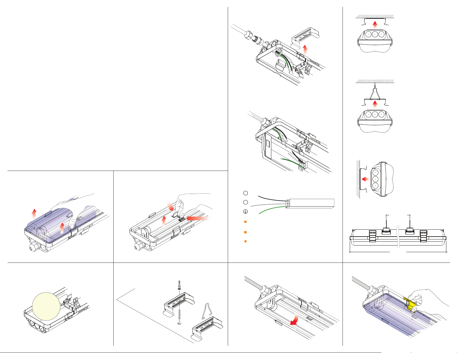
5-Fixture Body Mounting
When using electrical equipment, basic
safety precautions should always be
followed including the following:
READ AND FOLLOW ALL SAFETY
INSTRUCTIONS
Do not let power cords touch hot surfaces.
Do not mount near gas or electric heaters.
Equipment should be mounted in locations
and at heights where unauthorized personnel
will not readily subject it to tampering.
The use of accessory equipment not recommended
by Beghelli Inc, may cause an unsafe condition,
and will void the unit’s warranty.
Do not use this equipment for other than its
intended purpose.
Servicing of this equipment should be
performed by qualified service personnel.
SAVE THESE INSTRUCTIONS!
1-Remove Lens / Diffuser
1.
Remove Lens / Diffuser.
2.
Remove the reflector
3.
Remove the mounting hardware bag.
4.
Securely mount the fixture hardware
The fixture can be snapped onto
5.
the hardware as illustrated.
Pass AC power wires through previously
drilled holes(s) and connector(s).
6.
Hang Reflector From Internal Clips
Connect AC supply and ground as labeled
on the provided wire leads.
Insulate unused wire!
CAUTION! Failure to insulate unused
wire may result in a shock hazard or
unsafe condition as well as equipment
failure.Route wires and secure them in place.
7.
Install the lamp into the lamp holder and
turn to lock it into place.
8.
closure clips. Replace the lens and
Install
snap each of the eight (8) clips into place
9.
Turn on AC voltage
2-Remove Reflector
6-Hang Reflector From Internal Clips
and Connect AC Supply
reinstall reflector
6a-Electrical Connections
Line / Hot
L
Neutral / Common
N
Ground
Labeled wireleads are provided for
Line / Hot, Neutral / Common and Ground.
Labels will indicate the rated inputvoltage:
120-277VACor 347VAC 60Hz.
Exactballast and wiringconfiguration
may differ from image above:
FOLLOW ACTUAL WIRE LABELS.
L
B A L L A S T
N
ceiling mount
suspension mount
wall mount
35 1/2”
49 3/4
3-Remove Mounting Hardware Kit
4-Install Mounting Hardware
7-Install Lamp 8-Install Lens / Diffuser
 Loading...