

Page 1
EN
B.E.G.
LUXOMAT® RADAR
Installation and Operating Instruction for B.E.G. - RADAR-motion detector HF-MD2-SM
1. Product information
• High frequency motion detector, designed for surface mount
• Temperature-independent detection
• Detection can be made through various materials
• Range, twilight setting and light-on time set via dials
2. Operation
Contrary to motion detectors with passive infrared technology,
high frequency motion detectors emit a 5.8 GHz signal.
The measuring principle is also different: the change in frequency
of waves reected by a moving object is measured and in this
way a movement is detected (as is known by everyone from a
passing car with its siren switched on, e.g. police car or re
engine).
This principle works better when the signal source is frontally approached, and for that reason radar motion detectors are more
sen sitive to frontal approach compared to lateral passing by.
Moreover, this process is almost temperature-independent,
whereas temperature is the basis
for the PIR motion detectors‘ temperature measuring process.
Infrared waves do not pass through walls, but high frequency
waves do. As a consequence, a clearly sharp demarcation of
a room is not possible with HF technique, as it is with e.g. PIR
technique. Therefore, persons in neighbouring rooms may also be
detected and lights may be switched on.
After detection of a motion, the detector switches on the lights
during the predened period of time (approx. 5sec. - 15min.).
Transmitted power
Almost the same range of frequency as in W-LAN is used. The
hight-frequency output of the HF sensor is approx. 10mW - that‘s
just 1,00 th of the transmission power of a mobile phone or
mirowave oven.
< 10mW ca. 1000mW
3. Safety information
Work on the 230V mains supply may only be carried
out by qualified professionals or by instructed persons
under the direction and supervision of qualified skilled
!
electrical personnel in accordance with electrotechnical
regulations.
Disconnect the power supply before attempting any
!
work on the unit!
This device is not suitable for disconnection.
!
Please note:
To optimise the service life of fluorescent compact lights, we
recommend a minimum switch-on time of 5min. for the HF
detector.
4. Installation
The circular cover ring must be removed prior to assembly. To do
this, twist the lens anticlockwise through approximately 5° and lift
off.
Having connected up the wires in accordance with regulations, secure the detector with 2 screws (∅ 6 mm). After installation replace
the lens and lock (turn clockwise).
Mains to be connected.
5. Putting into operation / Settings
Fig. 1
N L L‘
Connections:
Fig. 2
Rotary control dial:
A
B
D
Fig. 3
2 - 2000 Lux
5 sec. - 15min.
Ø
0.4 - 16 m
LOWOFFHIGH
Range switch C:
Twilight setting (Rotary control dial A)
The chosen light response threshold can be innitely
varied from approx.
Symbol “MOON” = dusk-to-dawn operation
Symbol “SUN” = daylight operation
Time setting (Rotary control dial B)
The light can be set to stay ON for any period of
time between approx. 5 sec. and a maximum of
15min. Any movement detected before this time
elapses will re-start the timer. There will be no
twilight evaluation (daytime operation) for as long
as the motion detector is switched on.
Note: After the light switches OFF, it takes approx.
1sec. before it is able to start detecting movement
again.
Range/Sensitivity
Range/sensitivity of the sensor can be reduced over
switch C and potentiometer D.
Switch C =
approx. 0.4 - 16m Ø.
Switch C =
between approx. 6 - 16m Ø.
Switch C =
Note: We recommend to adjust the range starting at
the maximum and then reducing it, if not time delay
may occur while setting the range.
Test setting
In order to adjust the detection range during the day, the twilight value must be set to day (“sun“ symbol) and time should
be set to the minimum (approx. 5 sec.).
2 - 2000Lux
(Switch C,
“LOW”
: Range can be adjusted between
“HIGH”
: Range can be adjusted
“OFF”
: Detector is switched off.
.
Rotary control dial
D)
6. Dimensions
Ø 116.5 mm
7. Connections (Fig. 1)
Connect power supply as indicated in the terminal connection:
Phase = L
Connected phase = L’
Neutral conductor = N
Note: This appliance is made out of synthetic material and of
class II, it does not need a protective conductor.
Attention: To ensure a long lifespan, we advise the use of an
external relay for lamps with a long starting current.
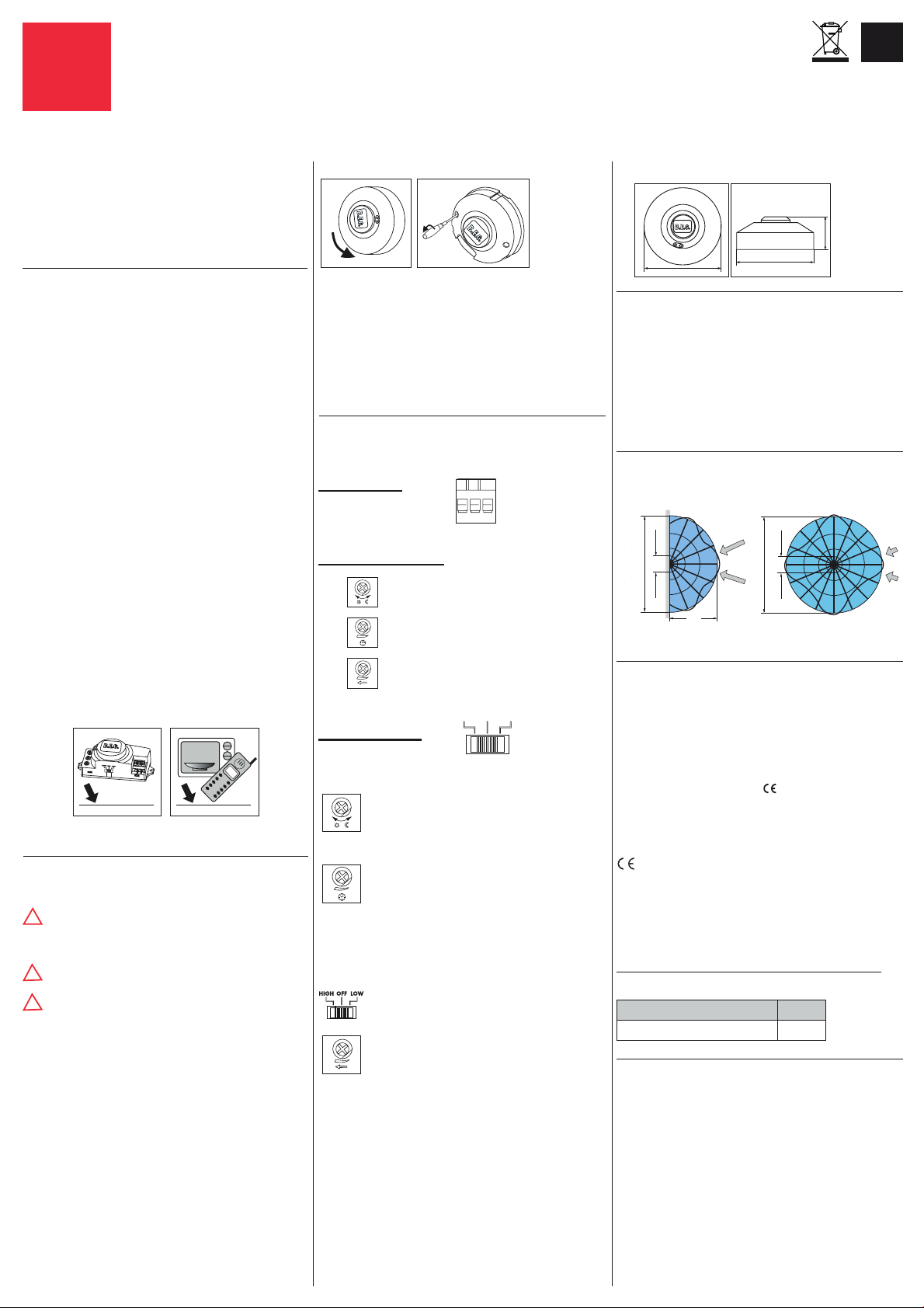
8. Range of Coverage max.
(Mounting height = 2.50 m / Switch C = “HIGH”)
Wall mounting Ceiling mounting
16
0.4
16
0.4
8
Walking towards = Best detection
9. Technical data
Power supply: 230 VAC ±10%
Switching power: 1200W, cos φ =1
600 VA, cos φ =0.5 µ-Contact
Time settings: approx. 5sec. - 15min.
Photo electric switch: 2 - 2000 Lux
HF-transmitter consumption: 5.8 GHz, < 10mW, ISM Band
Power consumption: < 1W
Protection: IP20 (only for inside use)
Class: II/
Ambient temperature: -15°C to +50°C
Note: When taking the detector into operation or after each power
failure, the motion detector will switch on for a duration of 3 seconds.
Declaration of Conformity:
This product respects the directives concerning
1. electromagnetic compatibility (2004/108/EU)
2. low voltage (2006/95/EU)
3. restriction of the use of certain hazardous substances in electrical
and electronic equipment (2011/65/EU)
10. Article / Part nr.
Type Part nr.
HF-MD2-SM 94402
11. Fault-finding / Troubleshooting
Light not illuminated
Twilight-value not reconcilable with the given situation
Adjust twilight-value with regulating screw
Light illuminated constantly during darkness
Constant movement activity in the area of coverage
If movements caused by sources of interference (animals, ventilation,
etc.), remove from area of coverage
Reduce range/ sensivity with “SENS” regulating screw
Light illuminated constantly, also during the day
Twilight-value not reconcilable with the given situation
Adjust twilight-value with regulating screw
Light will not switch
Mechanical
Check bulb
Check connection
Ø 116.5 mm
16
0.4
16
0.4
45mm
MAN 8017 – 031215-6
 Loading...