

BeFree BF15-1.0/2-A1, BF15-1.0/2-D1, BF15-1.0/2-C1, BF15-1.0/3-A1, BF15-1.0/3-D1 User Manual
...Page 1
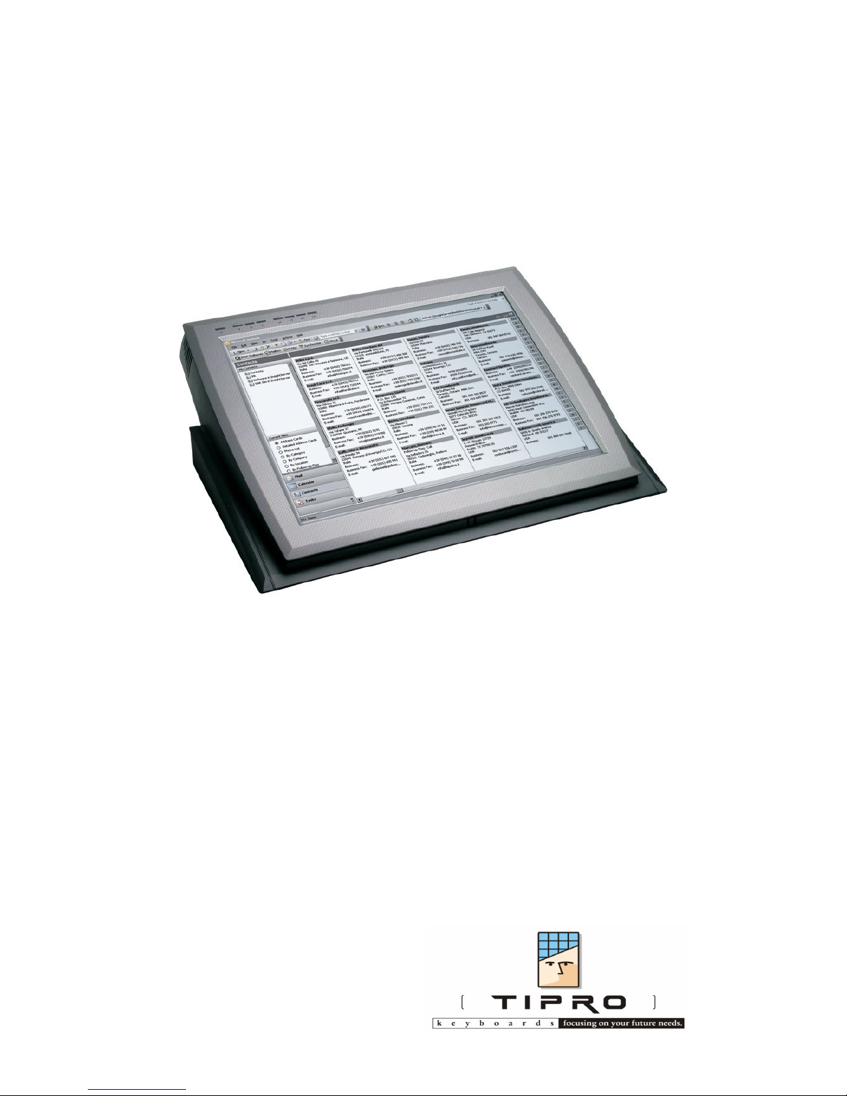
BeFREE
V2 (Intel based)
User manual
For versions:
BF15-1.0/2-A1-xxx BF15-1.0/2-C1-xxx
BF15-1.0/3-A1-xxx BF15-1.0/3-C1-xxx
BF15-1.5/2-A1-xxx BF15-1.0/2-D1-xxx
BF15-1.5/3-A1-xxx BF15-1.0/3-D1-xxx
BeFREE_UM_2_52.doc
Version: 2.52
March 20, 2009
Page 2

Contents:
1 GENERAL OVERVIEW ......................................................................................................................... 1-1
1.1
W
HAT IS WHAT
1.2
W
HAT IS NEW
1.3
W
HERE IS WHAT
1.4
P
ACKAGE CONTENTS
1.5
G
ETTING STARTED
1.6
C
ABLE MANAGEMENT
1.7
S
TATUS
2 WARNINGS.............................................................................................................................................. 2-1
2.1
G
ENERAL PRECAUTIONS FOR TIPRO PRODUCTS
2.1.1 Damage Requiring Service........................................................................................................... 2-1
2.2
S
ERVICING
2.3
M
OUNTING ACCESSORIES
2.4
V
ENTILATION
2.5
W
ATER AND MOISTURE
2.6
P
OWER SOURCES
2.7
A
CCESSIBILITY
2.8
V
OLTAGE SELECT SWITCH
2.9
I
NTERNAL BATTERY
2.10 E
2.11 O
2.12 C
2.13 H
2.14 C
2.15 R
2.16 O
2.17 O
2.18 P
2.19 C
3 VERSIONS................................................................................................................................................ 3-1
3.1
3.2
4 SPECIFICATIONS .................................................................................................................................. 4-1
4.1
XTENSION CORD
VERLOADING
LEANING
EAT
................................................................................................................................................. 2-3
IRCULATION AND COOLING
EPLACEMENT PARTS
PTIONS AND UPGRADES
BJECT ENTRY
OWERED PORTS
ASH DRAWER
C
ONNECTIVITY
3.1.1 Standard ....................................................................................................................................... 3-2
3.1.2 Powered........................................................................................................................................ 3-3
3.1.3 Fanless ......................................................................................................................................... 3-4
C
ONNECTOR SPECIFICATIONS
3.2.1 12/24V input ................................................................................................................................. 3-4
3.2.2 24V output .................................................................................................................................... 3-4
3.2.3 12V output .................................................................................................................................... 3-5
3.2.4 Tipro external bus ........................................................................................................................ 3-5
3.2.5 Serial port..................................................................................................................................... 3-5
3.2.6 USB .............................................................................................................................................. 3-6
3.2.7 Powered USB 12V ........................................................................................................................ 3-6
3.2.8 Powered USB 24V ........................................................................................................................ 3-6
3.2.9 Ethernet ........................................................................................................................................ 3-6
3.2.10
PS/2 keyboard/mouse .............................................................................................................. 3-7
3.2.11
VGA ......................................................................................................................................... 3-7
3.2.12
Cashdrawer ............................................................................................................................. 3-7
S
PECIFICATION COMMON FOR ALL VERSIONS
4.1.1 Environmental .............................................................................................................................. 4-1
4.1.2 Dimensions ................................................................................................................................... 4-1
4.1.3 Specifications of motherboard...................................................................................................... 4-1
4.1.4 Harddisk ....................................................................................................................................... 4-1
4.1.5 RAM.............................................................................................................................................. 4-1
4.1.6 TFT LCD ...................................................................................................................................... 4-2
?................................................................................................................................. 1-1
?................................................................................................................................... 1-1
?............................................................................................................................... 1-2
......................................................................................................................... 1-2
............................................................................................................................. 1-3
....................................................................................................................... 1-3
LEDS.................................................................................................................................... 1-4
................................................................................. 2-1
......................................................................................................................................... 2-1
.................................................................................................................. 2-1
..................................................................................................................................... 2-2
..................................................................................................................... 2-2
............................................................................................................................... 2-2
.................................................................................................................................. 2-2
................................................................................................................. 2-2
.......................................................................................................................... 2-2
.............................................................................................................................. 2-2
................................................................................................................................... 2-2
.......................................................................................................................................... 2-2
............................................................................................................. 2-3
........................................................................................................................ 2-3
................................................................................................................... 2-3
.................................................................................................................................. 2-3
................................................................................................................................ 2-3
.................................................................................................................................. 2-3
.................................................................................................................................. 3-2
............................................................................................................. 3-4
..................................................................................... 4-1
II
Page 3

Contents:
4.1.7 Touch panel .................................................................................................................................. 4-2
4.1.8 Tipro Controller ........................................................................................................................... 4-2
4.1.9 Fan control ................................................................................................................................... 4-3
4.2
P
OWER CONSUMPTION
4.2.1 BeFREE with 1.0 GHz processor:................................................................................................ 4-4
4.2.2 BeFREE with 1.5 GHz. Processor: .............................................................................................. 4-4
4.3
S
TANDARD AND FANLESS VERSION
4.3.1 Power supply ................................................................................................................................ 4-5
4.3.2 Peripherals power restrictions ..................................................................................................... 4-5
4.4
P
OWERED VERSION
4.4.1 Power Supply................................................................................................................................ 4-6
4.4.2 Peripherals power restrictions ..................................................................................................... 4-6
4.4.3 Cash Drawer ................................................................................................................................ 4-6
4.4.4 Explanation of programming Cash Drawer Ports ....................................................................... 4-7
5 INSTALLATION...................................................................................................................................... 5-1
5.1
D
RIVER INSTALLATION UNDER WINDOWS
5.1.1 Step 1, chipset drivers .................................................................................................................. 5-1
5.1.2 Step 2, graphics drivers ................................................................................................................ 5-1
5.1.3 Step 3, Ethernet drivers ................................................................................................................ 5-1
5.1.4 Step 4, audio drivers..................................................................................................................... 5-1
5.1.5 Step 5, Touch screen drivers ........................................................................................................ 5-2
5.1.6 Step 6, Virtual COM drivers – OPTIONAL.................................................................................. 5-2
5.1.7 ChangeMe installation ................................................................................................................. 5-2
5.2
D
RIVER INSTALLATION FOR LINUX AND OTHER OPERATING SYSTEMS
5.3
C
HANGEME
5.3.1 Fan control ................................................................................................................................... 5-5
5.3.2 Cashdrawer .................................................................................................................................. 5-5
5.3.3 Advanced: ON/OFF ..................................................................................................................... 5-6
5.3.4 Advanced: LED functionality ....................................................................................................... 5-7
5.4
HOW TO
5.5
S
ETTING OF THE VOLTAGE ON THE POWERED
5.5.1 COM 2.......................................................................................................................................... 5-9
5.5.2 COM3 and COM4 ...................................................................................................................... 5-10
5.6
C
ASH DRAWER JUMPER SETTING
5.7
R
EPLACING HARDDISK
5.8
R
EPLACING
5.9
C
LEANING
5.10 J
6 BIOS SETTINGS...................................................................................................................................... 6-1
6.1
6.2
6.3
6.4
6.5
UMPERS
5.10.1
5.10.2
5.10.3
S
YSTEM TEST AND INITIALIZATION
S
YSTEM CONFIGURATION VERIFICATION
A
WARD
E
NTERING SETUP
M
AIN MENU
6.5.1 Setup Items: .................................................................................................................................. 6-2
6.5.2 STANDARD CMOS FEATURES .................................................................................................. 6-3
6.5.3 Advanced BIOS features............................................................................................................... 6-3
6.5.4 Advanced Chipset Features .......................................................................................................... 6-3
6.5.5 Integrated Peripherals ................................................................................................................. 6-3
6.5.6 Power Management Setup ............................................................................................................ 6-4
6.5.7 PnP/PCI Configurations .............................................................................................................. 6-5
6.5.8 PC Health Status .......................................................................................................................... 6-5
6.5.9 Frequency/Voltage Control .......................................................................................................... 6-5
6.5.10
6.5.11
....................................................................................................................................... 5-4
OPEN BE
RAM ............................................................................................................................ 5-12
........................................................................................................................................ 5-12
.......................................................................................................................................... 5-13
Clear CMOS .......................................................................................................................... 5-13
Bypass ON/OFF logic. .......................................................................................................... 5-13
Tipro Controller serial communication................................................................................. 5-14
BIOS S
....................................................................................................................................... 6-1
Load Fail-Safe Defaults........................................................................................................... 6-5
Load Optimized Defaults ......................................................................................................... 6-5
....................................................................................................................... 4-4
.................................................................................................... 4-5
............................................................................................................................ 4-6
XP ................................................................................... 5-1
.............................................. 5-3
FREE................................................................................................................... 5-8
COM
PORTS
................................................................ 5-9
...................................................................................................... 5-11
.................................................................................................................... 5-11
................................................................................................... 6-1
............................................................................................ 6-1
ETUP
......................................................................................................................... 6-1
............................................................................................................................... 6-1
III
Page 4

Contents:
7 REFERENCES: ........................................................................................................................................ 7-1
IV
Page 5

Records of Revision:
RECORDS OF REVISION
REVISION
1 14.04.2008
2 31.07.2008
3 01.10.2008
4 14.01.2009
5 06.02.2009
5.1 24.02.2009
DATE
PAGE
1st Issue B.Scholten
updated some pictures B.Scholten
Added Celeron 1.5 GHz. B.Scholten
Updated BIOS description B.Scholten
Added RS232 communication controller B.Scholten
Added status LED description B.Scholten
SUMMARY AUTHOR
5.2 20.03.2009 5-14 Corrected jumper setting in 5.10.3 B.Scholten
• Award is a trademark of Award Software International, Inc.
• CompactFlash™ is a trademark of the Compact Flash Association.
• Intel®, Pentium® M, and Celeron® M are trademarks of Intel® Corporation.
• Microsoft Windows® is a registered trademark of Microsoft Corp.
• ITE is a trademark of Integrated Technology Express, Inc.
• IBM, PC/AT, PS/2, and VGA are trademarks of International Business Machines Corporation.
• SoundBlaster is a trademark of Creative Labs, Inc.
V
Page 6

General overview
1 General overview
1.1 What is what?
Tipro’s BeFREE is a newly developed module. BeFREE is an integration of PC and a LCD
touch screen, based on the existing FREE+ line. Therefore BeFREE is compatible with all
existing and future FREE/FREE+ line modules. The BeFREE offers full connectivity in a
very compact form and allows for easy-access serviceability. A special low heat producing
processor is used, which is powerful enough for most tasks (except gaming and server
applications). Due to low heat components and special design BeFREE produces very low
noise levels.
BeFREE is built in the housing of the original 15” FREE+. It consist of an industrial grade
motherboard, hard disk, DC/DC converter, touch screen, high brightness TFT and Tipro
controller.
1.2 What is new?
Version 2 of BeFREE has some significant changes to the first version, though general
characteristics as shape, modularity and serviceability remained the same.
The biggest change is the move from VIA chipset and processor to an Intel based platform.
The nominal speed of the processor stayed (1.0GHz.) but the performance improved
dramatically.
Besides the basic 1.0 GHz. processor, also a 1.5Ghz. processor is offered, with the same
chipset.
All internal electronics have been redesigned as well as all metal parts of the “drawer”.
1-1
Page 7
3
1
2
3
4
5
4
1
2
6
1.3 Where is what?
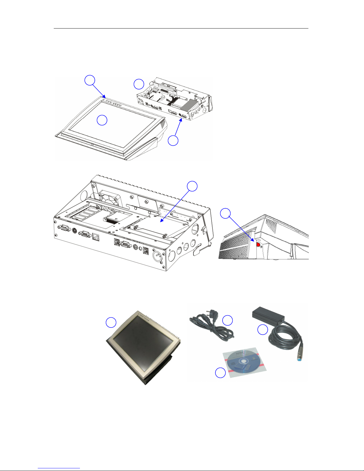
Figure 1- BeFREE (top part and PC part)
General overview
1 - Housing
– High brightness TFT
– Touch screen
2 - PC part of BeFREE
– Tipro controller
– Hard disk
– Processor
– DC-DC converter
– Motherboard
– Connector plate
3 - Hard disk
4 - Connector plate
5 - ON/OFF button
6 - Status LEDs
Figure 2- PC part of BeFREE (upside down)
1.4 Package Contents
1. BeFREE
2. Power supply
3. Power cord (EU)
4. CD with drivers and documentation
Figure 3 - left rear view
1-2
Page 8
General overview
1.5 Getting Started
1. Place the BeFREE on a flat and even surface
2. If desired, connect devices like keyboard, network, etc.
3. Connect the external power supply to the BeFREE.
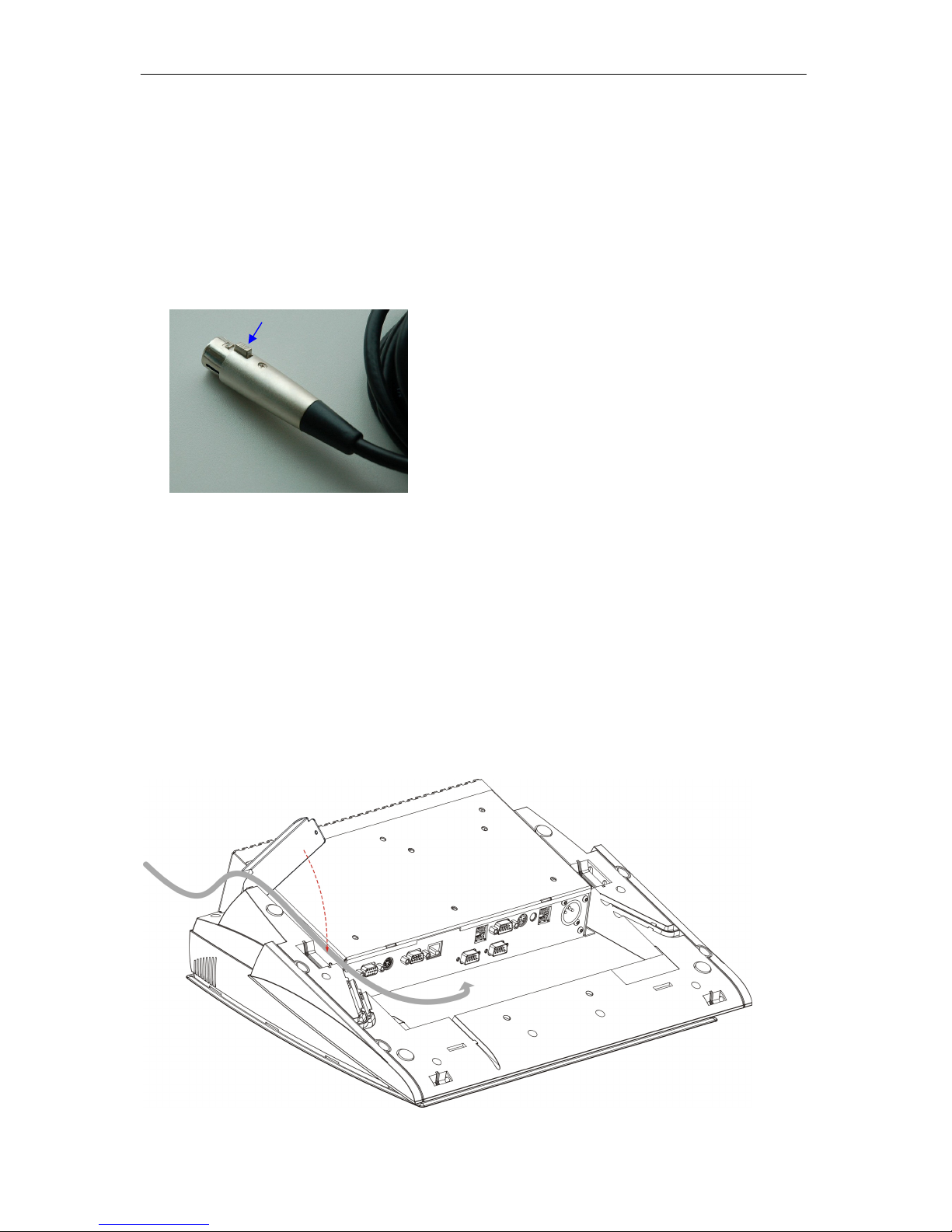
To remove the connector, the button must be pressed while pulling the connector.
4. Connect the power supply mains cable to the outlet.
5. Press the ON/OFF button (see 1.3, point 5 -). It might take a few seconds before the image
appears.
6. The system can be turned off either by the Operating System, or by pressing the ON/OFF
button (you might need to hold it for a few seconds)
1.6 Cable Management
Cables can be fixed in place with the cable management.
Open the mechanism as indicated below and guide the cables through.
Figure 4 - cable management
1-3
Page 9
General overview
1.7 Status LEDs
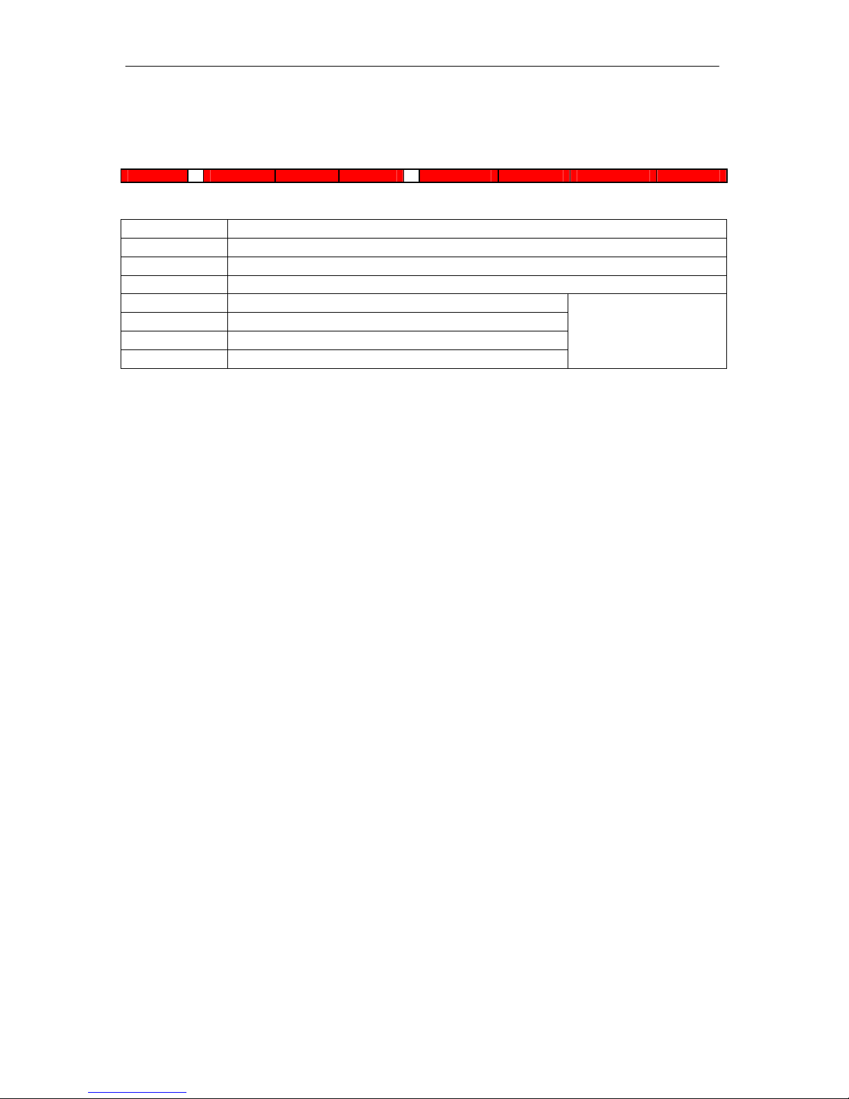
AC/DC on PC on CapsLock HDD FAN off FAN on FAN max FAN error
AC/DC on BeFREE is connected to to external power supply and is powered
PC on BeFREE is started
CapsLock CapsLock is on
HDD Harddisk is working
Fan off Inside temperature is lower than treshold, fan is off
Fan on Fan is working, speed is regulated
Fan max Fan is working at 100%, chance of overheating
Fan error Error in fan speed regulation
See also 4.1.9
1-4
Page 10

Warnings
2 Warnings
Tipro products are designed to operate safely when installed and used according to the
product instructions and general safety practices. The guidelines included in this chapter
explain the potential risks associated with BeFREE operation and provide important safety
practices designed to minimize these risks. By carefully following the information contained
in this chapter, you can protect yourself from hazards and create a safer BeFREE work
environment.
2.1 General Precautions for Tipro Products
Retain the safety and operating instructions provided with the product for future reference.
Follow all operating and usage instructions. Observe all warnings on the product and in the
operating instructions. To reduce the risk of fire, bodily injury, and damage to the equipment,
observes the following precautions.
2.1.1 Damage Requiring Service
Unplug the product from the electrical outlet and take the product to a Tipro authorized
service provider under the following conditions:
• The power cord, extension cord, or plug is damaged.
• Liquid has been spilled or an object has fallen into the product.
• The product has been exposed to water.
• The product has been dropped or damaged in any way.
• There are noticeable signs of overheating.
• The product does not operate normally when you follow the operating
instructions.
2.2 Servicing
Except as explained elsewhere in the Tipro documentation, do not service any Tipro product
yourself. Always remove the power cord before opening the BeFREE. Never run the PC-part
of BeFREE separately from the screen and housing. Opening, removing covers or running
PC-part separately may expose you to electric shock. Service needed on components inside
these compartments should be done by a Tipro authorized service provider.
2.3 Mounting Accessories
Do not use the product on an unstable table, cart, stand, tripod, or bracket. The product may
fall, causing serious bodily injury and serious damage to the product. Use only with a table,
cart, stand, or bracket recommended by Tipro, or sold with the product.
2-1
Page 11

Warnings
2.4 Ventilation
Slots and openings in the product are provided for ventilation and should never be blocked or
covered, since these ensure reliable operation of the product and protect it from overheating.
The openings should never be blocked by placing the product on a bed, sofa, carpet, or other
similar, flexible surface. The product should not be placed in a built-in apparatus such as a
bookcase or rack unless the apparatus has been specifically designed to accommodate the
product, proper ventilation is provided for the product, and the product instructions have been
followed.
Make sure also the external power supply has enough free space around for heat dissipation.
2.5 Water and Moisture
Do not use the product in a wet location. BeFREE is not waterproof.
2.6 Power Sources
The product should be operated only from the type of power source indicated on the product’s
electrical ratings label. If you have questions about the type of power source to use, contact
your Tipro authorized service provider or local power company.
2.7 Accessibility
Be sure that the power outlet you plug the power cord into is easily accessible and located as
close to the equipment operator as possible. When you need to disconnect power to the
equipment, be sure to unplug the power cord from the electrical outlet.
2.8 Voltage Select Switch
Ensure that the voltage select switch, if provided on the product, is in the correct position for
the type of voltage in your country (115 VAC or 230 VAC).
2.9 Internal Battery
Your computer may contain an internal battery-powered real-time clock circuit. Do not
attempt to recharge the battery, disassemble it, immerse it in water, or dispose of it in fire.
Replacement should be done by a Tipro authorized service provider.
2.10 Extension Cord
If an extension cord or power strip is used, make sure that the cord or strip is rated for the
product and that the total ampere ratings of all products plugged into the extension cord or
power strip do not exceed 80% of the extension cord or strip ampere rating limit.
2.11 Overloading
Do not overload an electrical outlet, power strip, or convenience receptacle. The overall
system load must not exceed 80% of the branch circuit rating. If power strips are used, the
load should not exceed 80% of the power strip input rating.
2.12 Cleaning
Unplug the product from the wall outlet before cleaning. Do not use liquid cleaners or aerosol
cleaners. Use a damp cloth for cleaning.
2-2
Page 12

Warnings
2.13 Heat
The product should be placed away from radiators, heat registers, stoves, or other pieces of
equipment (including amplifiers) that produce heat.
2.14 Circulation and Cooling
Allow sufficient air circulation around the BeFREE and the external power supply during use.
Prevent direct exposure to radiant heat sources.
2.15 Replacement Parts
When replacement parts are required, be sure the service provider uses replacement parts
specified by Tipro.
2.16 Options and Upgrades
Use only the options and upgrades recommended by Tipro.
2.17 Object Entry
Never push a foreign object through an opening in the product.
2.18 Powered ports
Maximum current per port is 3A.
See also 4.4.2 Peripherals power restrictions.
2.19 Cash Drawer
The cash drawer uses the modular connectors specifically designed for cash drawers. Do not
connect ordinary telephone line to these connectors.
2-3
Page 13

Versions
3 Versions
Currently there are 2 processors available for the same, Intel 852GM chipset;
- 1.0GHz Celeron M 0L2 cache
- 1.5GHz. Celeron M 512 kB L2 cache
All versions can be with either 512 MB or 1 GB RAM1.
There are 3 basic versions of BeFREE1:
1. Standard version, BF15-1.0/2-C1
2. Powered version, BF15-1.0/2-A1 and BF15-1.5/2-A1
3. Fanless version, BF15-1.0/2-D1
The following items are the same in all versions:
- TFT
- Touchscreen
- Housing for TFT
- Mainboard
- Tipro Connectivity
- Fan control
Differences are in power supply, both external AC/DC and internal DC/DC. The standard and
fanless versions are powered by 12V, the powered version by 24V.
The powered version offers more powered connectivity and can supply more current to
peripherals than the standard version.
Visually the difference can be noticed at the rear; The fanless version has a heatsink, the
powered version has a heatsink with integrated fan, the standard version has no heatsink, just
protection for the fan
The differences in connectivity are shown below
1
Not all variations might be in standard offer
3-1
Page 14
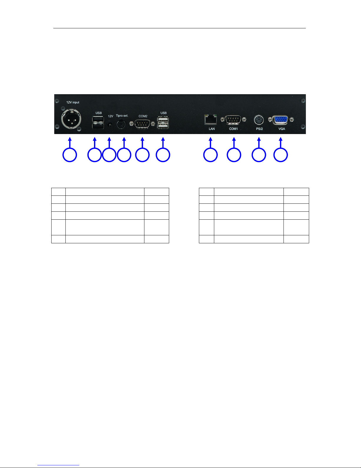
3.1 Connectivity
2 3 4 5 6 7 8 9 10
3.1.1 Standard
1
Versions
Figure 5 - Connector plate
No Connector details No Connector details
1 12V input 3.2.1 6 2x USB 2.0 3.2.6
2 2x USB 2.0 3.2.6 7 Ethernet 10/100 3.2.9
3 12V output 3.2.3 8 COM 1 3.2.5
4 Tipro external bus 3.2.4 9 PS/2 keyboard &
3.2.10
mouse
5 COM 2, powered (5/12V) 3.2.5 10 VGA, external display 3.2.11
3-2
Page 15
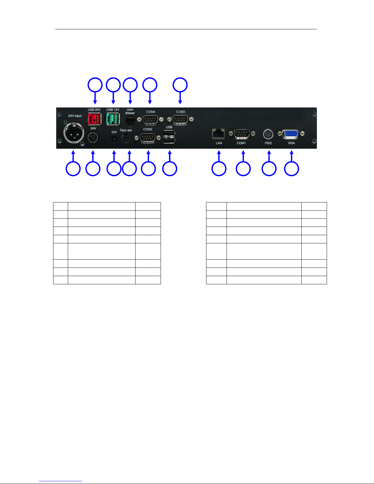
Versions
2 3 4 5 6 7 8 9 10
14 12 13 15
3.1.2 Powered
11
1
Figure 6 - Connector plate
No Connector details No Connector details
1 24V input 3.2.1 9 PS/2 keyboard & mouse 3.2.10
2 24V output 3.2.2 10 VGA, external display 3.2.11
3 12V output 3.2.3 11 Powered USB 24V 3.2.8
4 Tipro external bus 3.2.4 12 Powered USB 12V 3.2.7
5 COM 2, powered
3.2.5 13 Cash drawer 3.2.12
(5/12/24V)
6 2x USB 2.0 3.2.6 14 COM 4 3.2.5
7 Ethernet 10/100 3.2.9 15 COM 3 3.2.5
8 COM 1 3.2.5
3-3
Page 16
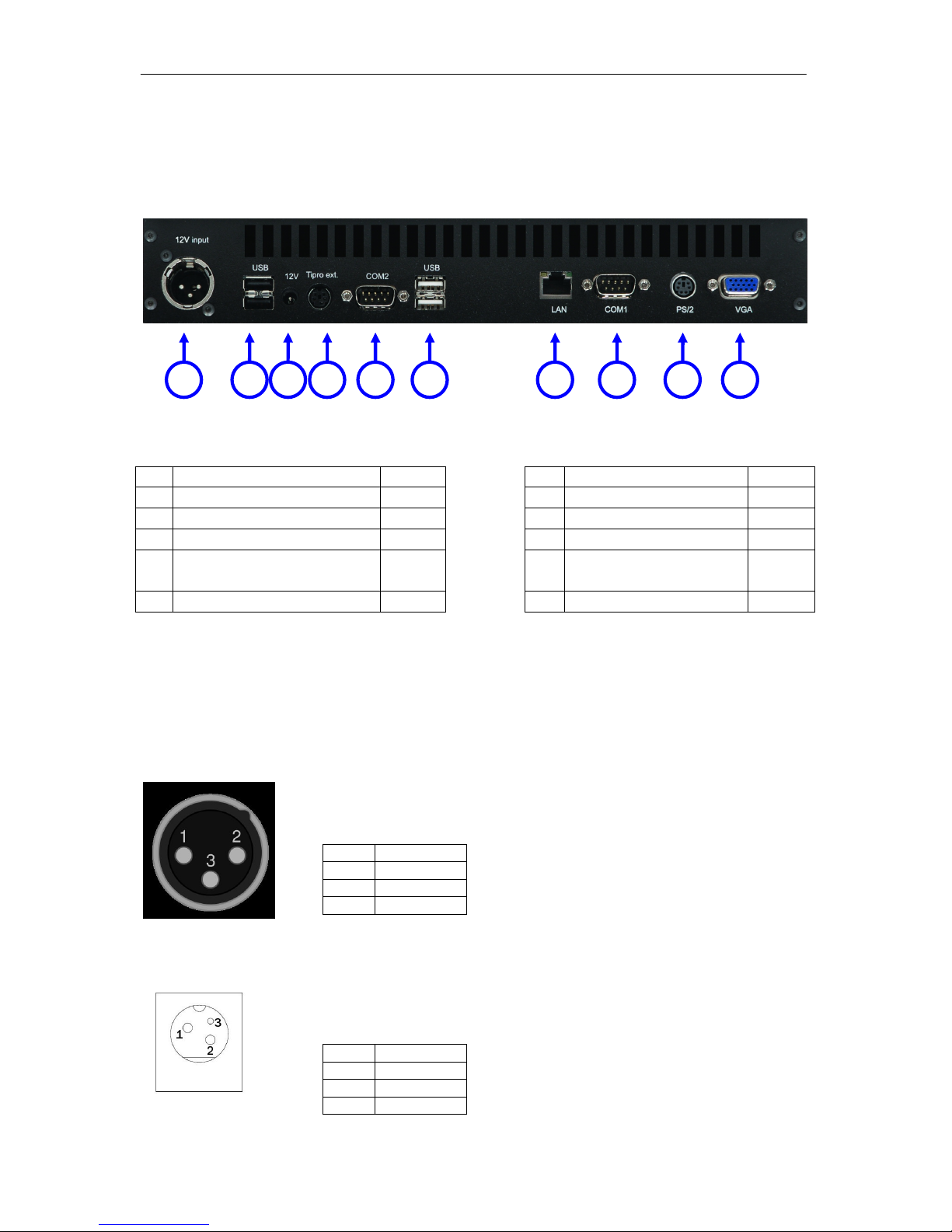
2 3 4 5 6 7 8 9 10
3.1.3 Fanless
1
Versions
Figure 7- Connector plate
No Connector details No Connector details
1 12V input 3.2.1 6 2x USB 2.0 3.2.6
2 2x USB 2.0 3.2.6 7 Ethernet 10/100 3.2.9
3 12V output 3.2.3 8 COM 1 3.2.5
4 Tipro external bus 3.2.4 9 PS/2 keyboard &
3.2.10
mouse
5 COM 2, powered (5/12V) 3.2.5 10 VGA, external display 3.2.11
3.2 Connector specifications
Pinout + rating
3.2.1 12/24V input
The input is either 24V or 12V, never both.
Pin # Name
1 +24V
2 GND
3 +12V
3.2.2 24V output
Pin # Name
1 +24V
2 GND
3 N.C.
3-4
Page 17
1
2
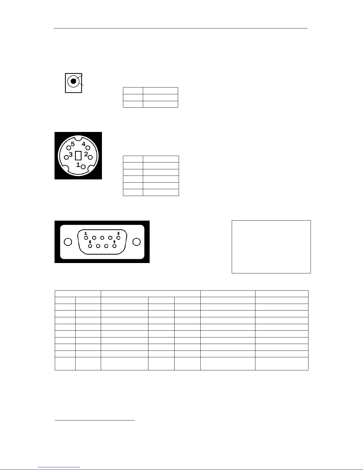
3.2.3 12V output
Versions
2.1 mm. connector.
Pin # Name
1 +12V
2 GND
3.2.4 Tipro external bus
Pin # Name
1 TBM_CLK
2 +VTBS
3 GND
4 TBM_DATA
5 EXT_CFG2
3.2.5 Serial port
Notes:
• +24V on pin 9 available
on Powered BeFREE.
• For current limitations
see 4.3.2 and 4.4.2.
COM 1 COM 2 COM 31 COM 41
Pin # RS232 RS232 RS422 RS485 RS232 RS232
1 DCD DCD TXD- TXD- DCD N/C
2 RX RX RXD+ N/C RX RX
3 TX TX TXD- TXD+ TX TX
4 DTR DTR RXD+ N/C DTR N/C
5 GND GND N/C N/C GND GND
6 DSR DSR N/C N/C DSR N/C
7 RTS RTS N/C N/C RTS N/C
8 CTS CTS N/C N/C CTS N/C
9 RI RI /+5V /+12V
/+24V
GND GND RI /+5V /+12V
/+24V
• To change RS232 to
RS422 or RS485 on
COM 2 see 6.5.5.3
RI /+5V /+12V
/+24V
1
COM 3 and COM 4 are so-called virtual COM ports; serial to USB devices. Drivers needed, see 5.1.6
3-5
Page 18
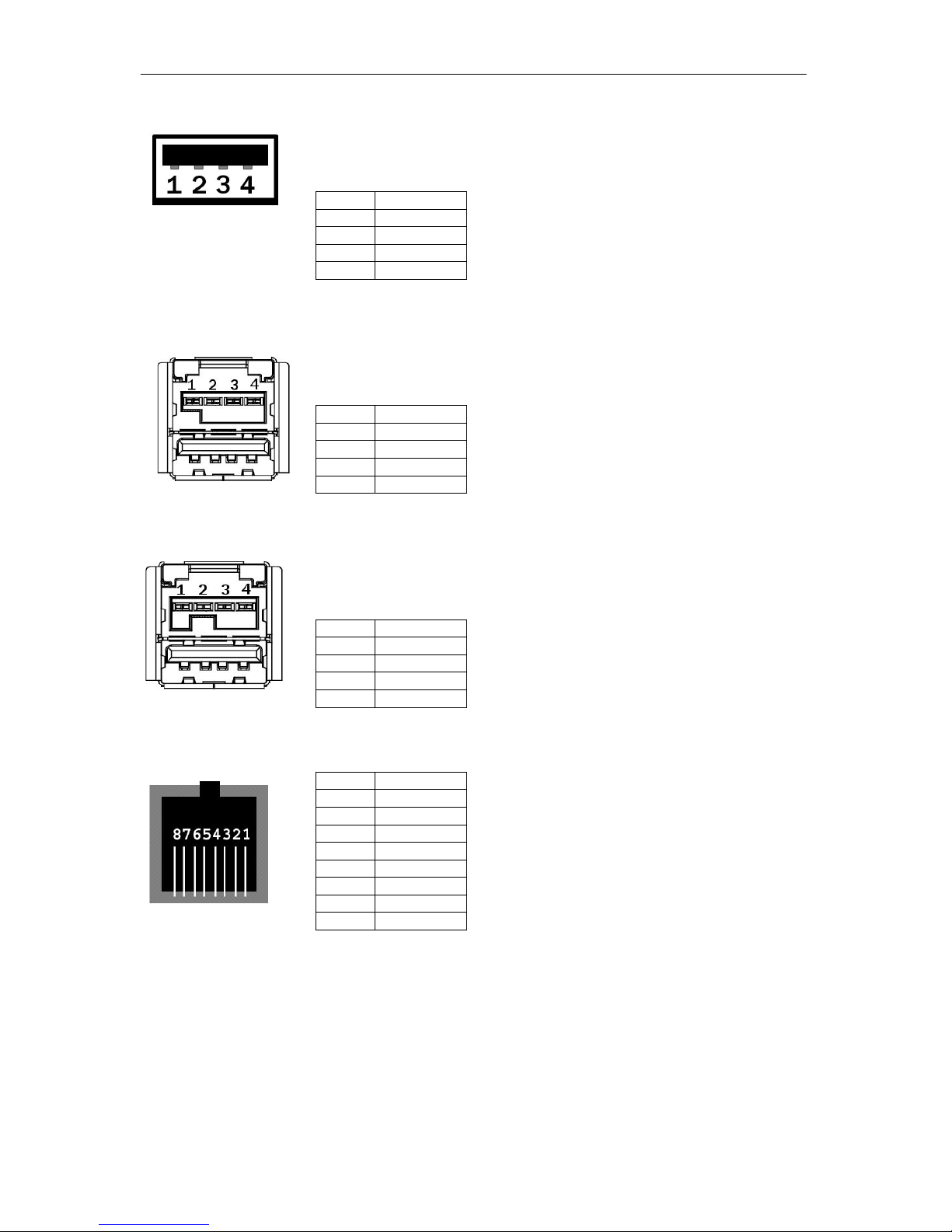
3.2.6 USB
All USB ports can provide 500mA on VBUS.
Pin # Name
1 VBUS
2 D3 D+
4 GND
3.2.7 Powered USB 12V
Pin out of USB part same as standard USB port, see 3.2.6.
Pin # Name
1 GND
2 +12V
3 +12V
4 GND
Versions
3.2.8 Powered USB 24V
Pin out of USB part same as standard USB port, see 3.2.6.
Pin # Name
1 GND
2 +24V
3 +24V
4 GND
3.2.9 Ethernet
Pin # Name
1 TX+
2 TX3 TCT
4 N/C
5 N/C
6 RCT
7 RX+
8 RX-
3-6
Page 19
Versions
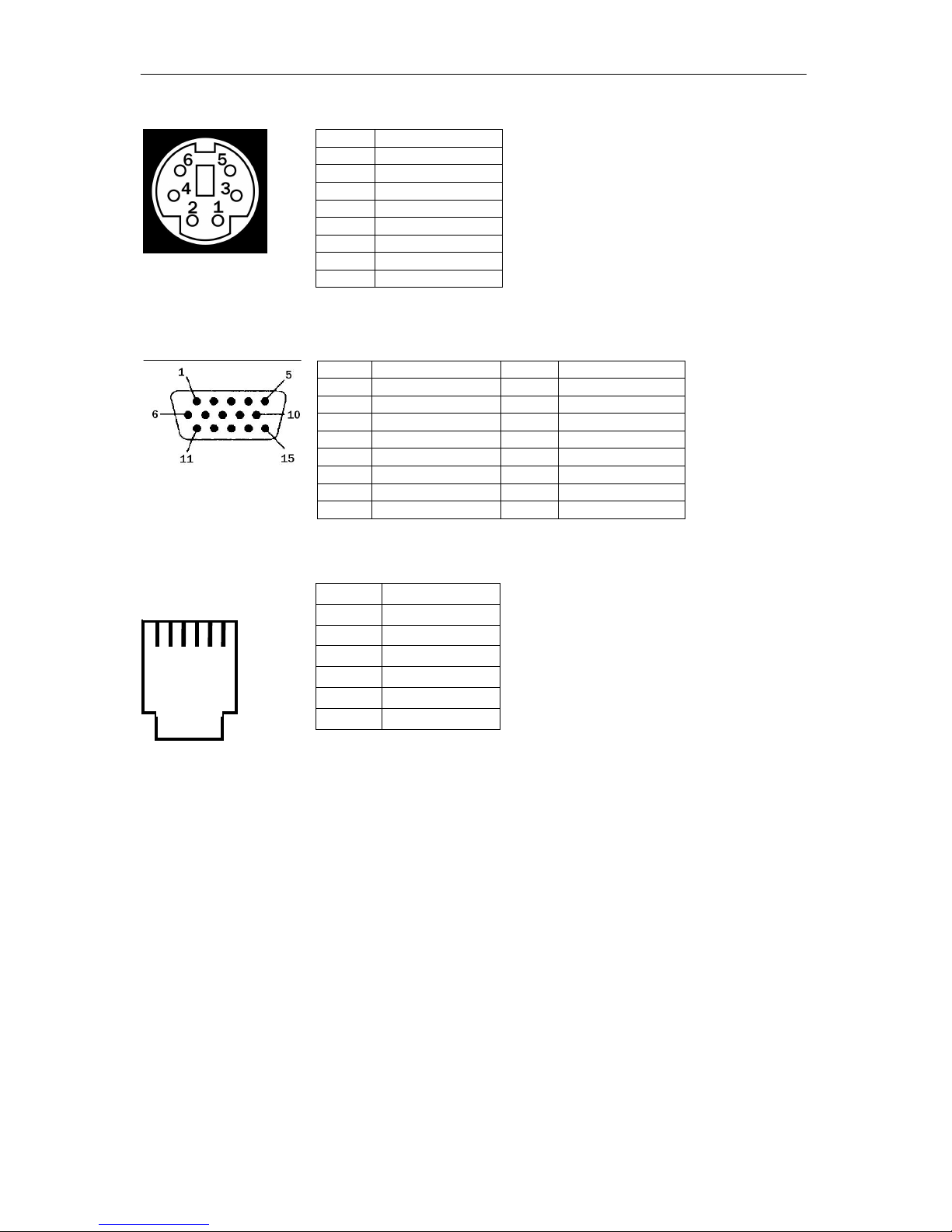
3.2.10 PS/2 keyboard/mouse
Pin # Name
1 Keyboard Data
2 Mouse Data
3 GND
4 Shield
5 +5V
6 Keyboard Clock
7 Shield
8 Mouse Clock
3.2.11 VGA
Pin # Name Pin # Name
1 CRT_RED 9 +5V
2 CRT_GREEN 10 VGA GND
3 CRT_BLUE 11 N/C
4 N/C 12 CRT_SDA
5 VGA GND 13 CRT_HSYNC
6 VGA GND 14 CRT_VSYNC
7 VGA GND 15 CRT_SCL
8 VGA GND
3.2.12 Cashdrawer
Pin # Name
1 Shield
2 Kick out 1
3 Open/Close
4 Power 24V
5 Kick out 2
6 GND
3-7
Page 20
Specifications
4 Specifications
4.1 Specification common for all versions
4.1.1 Environmental
4.1.1.1 Non-Operating
Temperature: -20 to 40oC, till 60oC if the relative humidity is < 27% RH
Humidity: 90% RH
4.1.1.2 Operating
Temperature: +5 to 30oC
Humidity: 90% RH
4.1.2 Dimensions
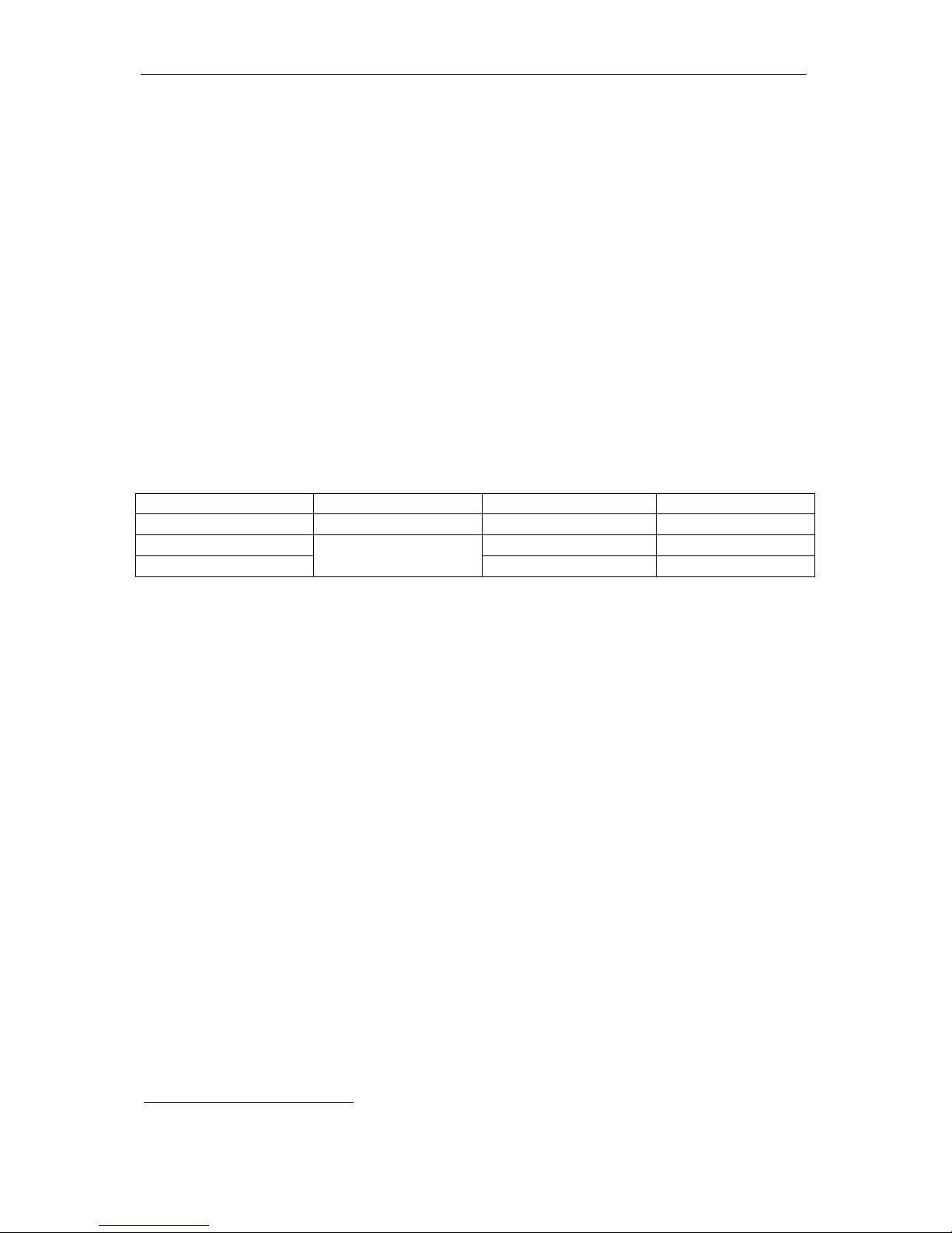
BeFREE Size [W x D x H] weight Power supply
Standard 409 x 328 x 109 mm. 5.95 kg. 30 x 58x 133 mm.
Powered 6.60 kg. 42 x 84 x 170 mm.
Fanless
409 x 343 x 109 mm.
6.50 kg 30 x 58x 133 mm.
4.1.3 Specifications of motherboard
• Chipset Intel 852GM + 82801 DB (ICH4)
• I/O Chipset ITE IT8712IX
• System Memory 200-pin DDR SODIMM x 1, Max. 1GB (DDR266)
• Dual-View LCD / CRT
• Ethernet Intel® 82562, 10/100Base-TX
4.1.4 Harddisk
• Interface: EIDE
• 2.5” formfactor
• 80 GB.1
• 8 MB. buffer
• 5.400 rpm. Rotational speed
4.1.5 RAM
• 200-pin DDR SODIMM
• 266 MHz.
• 512 or 1024 MB.
1
One gigabyte (GB.) = 1.000.000.000 bytes.
4-1
Page 21

Specifications
4.1.6 TFT LCD
The TFT display is an active matrix LCD with better resolution, sharper screen display and
broader viewing angle compared to passive matrix screens. 15.0” displays are used in
BeFREE.
• Samsung 15.0” LTM150XH-L06
• XGA 1024×768 display format
• Brightness: 430 typ cd/m
2
• Contrast ratio: 400 typ
• Viewing angle (upper/lower/left/right): 50/60/70/70
4.1.7 Touch panel
A resistive touch panel is made of glass plate, covered with a polyester sheet and coated with
additional layers that make an electrical contact on the pressed spot. It uses the five-wire
AccuTouch technology, which has a high touchpoint density and fast response. The surface of
touch screen is resistant to acetone, methylene, isopropyl-alcohol, ammonia and others.
• Accuracy : ±2mm
• Response time: <10ms
• Resolution: 4096×4096 touchpoints
• Lifetime: 35 million touches in one spot
4.1.8 Tipro Controller
Tipro controller is built in BeFREE. It controls Fan, Cashdrawer and all other (optional) Tipro
modules connected to BeFREE.
For monitoring, setting and programming modules, fan etc. ChangeMe is used, see 5.3. For
general programming please refer to ChangeMe Help file.
All BeFREE versions the Tipro Controller is communicatioon via the USB interface. USB is
used for both programming the controller and for sending key-events.
On powered BeFREEs it is possible to additionally connect the Tipro Controller to a COM
port.
In some cases this might be necessary, for instance when software expects data on serial
interface (i.e. data from MSR).
4-2
Page 22
Specifications
4.1.9 Fan control
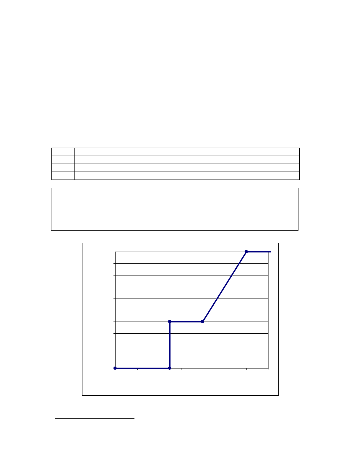
BeFREE has integrated a specially designed Fan control which ensures that BeFREE is
always producing as little noise as possible.
The Fan control is a device which controls fan speed proportionally to the BeFREE’s
temperature. In general that means the higher the temperature is, the greater the fan speed. See
chart on Figure 8 which shows Fan power (rotation) dependence of temperature.
Fan control can be reprogrammed if necessary (due to environment, etc.). Reprogramming can
be done by Tipro authorized service provider.
Temperature of BeFREE can be monitored in ChangeMe (see 5.3.1) or by using MIDAPI1
functions.
The status of the fancontrol is shown by the LEDs on the top of the frame labeled L1 to L4.
L1 Fan control is off
L2 Fan control is working, fanspeed is relative to temperature
L3 Temperature is over maximum, fan at 100%. Serious damage might occur!
L4 Error on fan control
Note:
Optionally the LEDs can display the current layer of the Tipro controller instead of the
FAN status.
Section 5.3.4 describes how to change this setting.
100%
90%
80%
70%
60%
50%
40%
Fan Power [ % ]
30%
20%
10%
0%
0˚C 10˚C 20˚C 30˚C 40˚C 50˚C 60˚C 70˚C
Temperature [ °C ]
Figure 8– Predefined Fan control settings
1
Tipro’s API. See MIDAPI documentation for more info
4-3
Page 23
Specifications
4.2 Power consumption
4.2.1 BeFREE with 1.0 GHz processor:
Stand by: 5W
Idle mode in Windows XP: 50W
100% disk and processor load: 56W
These are measured values with BeFREE without any additional Tipro modules and without
any other peripherals.
Power consumption is higher if you connect additional external devices (e.g. printers, displays
…)
4.2.2 BeFREE with 1.5 GHz. Processor:
Stand by: 5W
Idle mode in Windows XP: 56W
100% disk and processor load: 64W
These are measured values with BeFREE without any additional Tipro modules and without
any other peripherals.
Power consumption is higher if you connect additional external devices (e.g. printers,
displays, cash drawers …)
4-4
Page 24
Specifications
≤+⋅
=+⋅+⋅
4.3 Standard and Fanless version
4.3.1 Power supply
• Universal Input 100~240VAC, full range
• 80W @ 12V max output power
• Meets FCC/CISPR/VCCI class B EMI
• Operating Temperature : 0 to +40°C
• Storage Temperature : -20 to +85°C
• 3m. cord, XLR connector
4.3.2 Peripherals power restrictions
14W total available for external devices which has to be divided over 12 and 5V
Connection type: Maximum load per port Symbol Maximum power
allowed:
Tipro Bus
USB:
COM 5V:
COM 12V:
12V power output
1A
500 mA
1A
1A
1A
Calculation of total used power:
WPP
141.1
VV
125
Example:
Connected are:
- USB Keyboard with 30 mA consumption
- USB scanner. 155mA max.
Can we still connect a 8.4” customer display on 12V. Rating: 6W?
Calculate:
W105)155.003.0(1.1
So we can easily connect the display on 12V.
Together all devices will consume 7W and the maximum rating of the 12V connection (1A) is
lower than the display uses (0.5A)
P5V
P
12V
12W
14W
4-5
Page 25

4.4 Powered version
(
)
≤++
⋅
4.4.1 Power Supply
• Universal Input 100~240VAC, full range
• 150W @ 24V max output power
• Meets FCC/CISPR/VCCI class B EMI
• Operating Temperature : 0°C to +40°C
• Storage Temperature : -20°C to +85°C
• 3m. cord, XLR connector
4.4.2 Peripherals power restrictions
50W total available for external devices which has to be divided over 24/12/5V
Connection type: Maximum load per
port
Tipro bus
USB
COM 5V
COM 12V
Powered USB12V
12V output
COM 24V
Powered USB 24V
24V output
1 A
500 mA
1 A
1 A
3 A
1 A
1 A
3 A
2 A
Calculation of total used power:
VVV
24125
WPPP
501.1
Symbol Maximum power allowed:
P5V
P
12V
P
24V
12W
45W
50W
Specifications
4.4.3 Cash Drawer
BeFREE has one RJ12 connector (see Figure 6, No 13 and 3.2.12) for cash drawers.
The cash drawer uses the modular connectors.
Do not connect ordinary telephone line to these connectors.
The Cash drawers can be driven by Tipro controller or by the motherboards GPIO pins. By
default the cash drawers is driven by Tipro controller. If you want to change that, you have to
change jumper settings, see 5.6 Cash drawer jumper setting.
Cash drawer jumper setting is for advanced users only.
4-6
Page 26
Specifications
Important
4.4.4 Explanation of programming Cash Drawer Ports
4.4.4.1 OPOS:
If your Tipro OPOS drivers don’t support Cash drawer check on web site http://www.tipro.net
for latest drivers or contact Tipro support mail ([email protected]).
All supported OPOS commands can be found in UnifiedPOS document version 1.8 on page
139 (Chapter 4).
Cash drawer names are defined in registry:
(HKEY_LOCAL_MACHINE\SOFTWARE\OLEforRetail\ServiceOPOS\CashDrawer) and
are by default set to: TiproCashDrawer1 and TiproCashDrawer2.
They can be changed manually in the registry.
4.4.4.2 GPIO:
: When programming the Cashdrawer ports directly through the GPIO make
sure you program the open-signal as a pulse.
The ON signal should be maximum 20% of the whole signal. A typical ON pulse is
100ms. That means a typical signal has 100 ms. ON signal and at least 400ms. OFF.
For using GPIO pins you have to change jumpers, see Cash drawer jumper setting 5.6.
Address of the GPIO port is 0x801.
Our Cash drawer outputs are connected to port 6 and 8 (for sending open signal), and inputs
are connected to port 2 and 4 (reading status of Cash drawer - opened/closed)1.
BIOS Setting Connector Definition Address IT8712 GPIO Setting
Port 1 Bit 7 U35. pin 20 (GPIO27)
Port 2 Drawer 1, open/close1 Bit 6 U35. pin 21 (GPIO26)
Port 3 Bit 5 U35. pin 22 (GPIO25)
Port 4 Drawer 2, open/close1 Bit 4 U35. pin 23 (GPIO24)
Port 5 Bit 3 U35. pin 24 (GPIO23)
Port 6 Drawer 1, kickout Bit 2 U35. pin 25 (GPIO22)
Port 7 Bit 1 U35. pin 26 (GPIO21)
Port 8 Drawer 2, kickout Bit 0 U35. pin 27 (GPIO20)
1
Since the connector allows for only one open/close signal, the signal for both drawers is combined. So if either
one of the drawers is open both Drawer 1 and Drawer 2 indicate open.
4-7
Page 27
Installation
5 Installation
5.1 Driver installation under Windows XP
If you are using Windows XP then windows will find and install almost all drivers. The
drivers noted below must be installed manually from the enclosed CD.
Please always check our website for possible updates ( www.tipro.net/support ,then choose
BeFREE).
Note: If you have a powered BeFREE (BF15-1.x/x-A1-xxx) Windows will find new hardware
the first time you start, and it will ask you to install it. This is for the USB to serial, virtual
COM ports (see 5.1.6). You can cancel this automatic installation. When you come to step 6
below, the correct drivers will be installed.
5.1.1 Step 1, chipset drivers
Go to the directory named “Step 1 - Intel INF Update for Windows 9x-2003” and run
Setup.exe.
Click
and accept the license agreement. Click
You must restart the BeFREE, do this by choosing “Yes, I want to restart my computer now”
and click
.
again.
5.1.2 Step 2, graphics drivers
Open the directory “Step 2 - Intel Extreme Graphics 2 Driver”, then “Win2k_xp” and run
Setup.exe.
Click
and accept the license agreement.
Your screen might flicker during the installation, this is normal.
You must restart the BeFREE, do this by choosing “Yes, I want to restart my computer now”
and click
.
5.1.3 Step 3, Ethernet drivers
Open the directory “Step 3 - Intel LAN Driver”, then “2K_XP” and run pro2kxpm.exe.
Accept the licence agreement and click
. This extracts the installtion files to a directory,
by default “C:\IntelPRO”1.
The installtion starts automatically. choose:
When the installation is finished, press
. No restart is needed.
.
Note: for some unknown reason the window is sometimes displayed very small and cannot be
used. In this case close the window and go to the directory where the files were extracted to
and run setup.exe from there.
5.1.4 Step 4, audio drivers
This is only needed if you have a BeFREE with the optional audio connectivity.
Go to the directory “Step 4 - Realtek AC97 codec Driver” and run wdm_a361.exe
Click next to start the installation.
A warning message might appear stating that the software has not passed Windows Logo
testing. You can
.
1
After succesfull installation this directory can be deleted
5-1
Page 28
Installation
You must restart the BeFREE, do this by choosing “Yes, I want to restart my computer now”
and click
.
5.1.5 Step 5, Touch screen drivers
Open the directory “Step 5, ELO touchscreen driver”.
Run SW60650.exe.
Note: If you have a lower number (SW600390) please download updated drivers either from
our website (see 5.1) or from ELO www.elotouch.com then choose support, downloads,
current drivers.
Click to continue, then click
again.
Choose your language or leave default, and click
Select “Install USB Touchscreen Drivers” and click
to continue. After installing click
. The installation will start automatically after you press
.
. Then accept the licence agreement
.
The calibration should start automatically, (otherwise go to Start > Control Panel (classic
view) > ELO Touchscreen,
)
To calibrate press the shown targets (3) , test and accept the settings.
5.1.6 Step 6, Virtual COM drivers – OPTIONAL
This step is only needed when you have the powered BeFREE (BF15-1.x/x-A1-xxx)
Open the Directory “Step 6 optional – FTDI virtual COM driver” and run CDM2.02.4.exe.
Press
on the keyboard to finish the installation.
Windows will find new hardware, dual RS232
5.1.7 ChangeMe installation
Please check our website for the latest update (see 5.1).
Go to the “ChangeMe” directory and run Setup.exe.
Click
, you can optionally change the installation directory, click
“complete”,
again and finally
.
You must restart the BeFREE, do this by choosing “Yes, I want to restart my computer now”
and click
.
The first time you run ChangeMe (Start > All Programs > Tipro Keyboards > ChangeMe) it
will detect new hardware and install the Tipro Keyboard automatically.
Because this takes some time, the autodetect feaure of ChangeMe will not find the keyboard
at first. Wait untill Windows reports that the “new hardware is installed and ready to use”.
Now click
to detect the intergrated modules.
again, choose
5-2
Page 29
Installation
5.2 Driver installation for Linux and other Operating Systems
Other Operating systems are not actively supported by Tipro.
All hardware integrated does support Linux, but this might be limited to certain distributions.
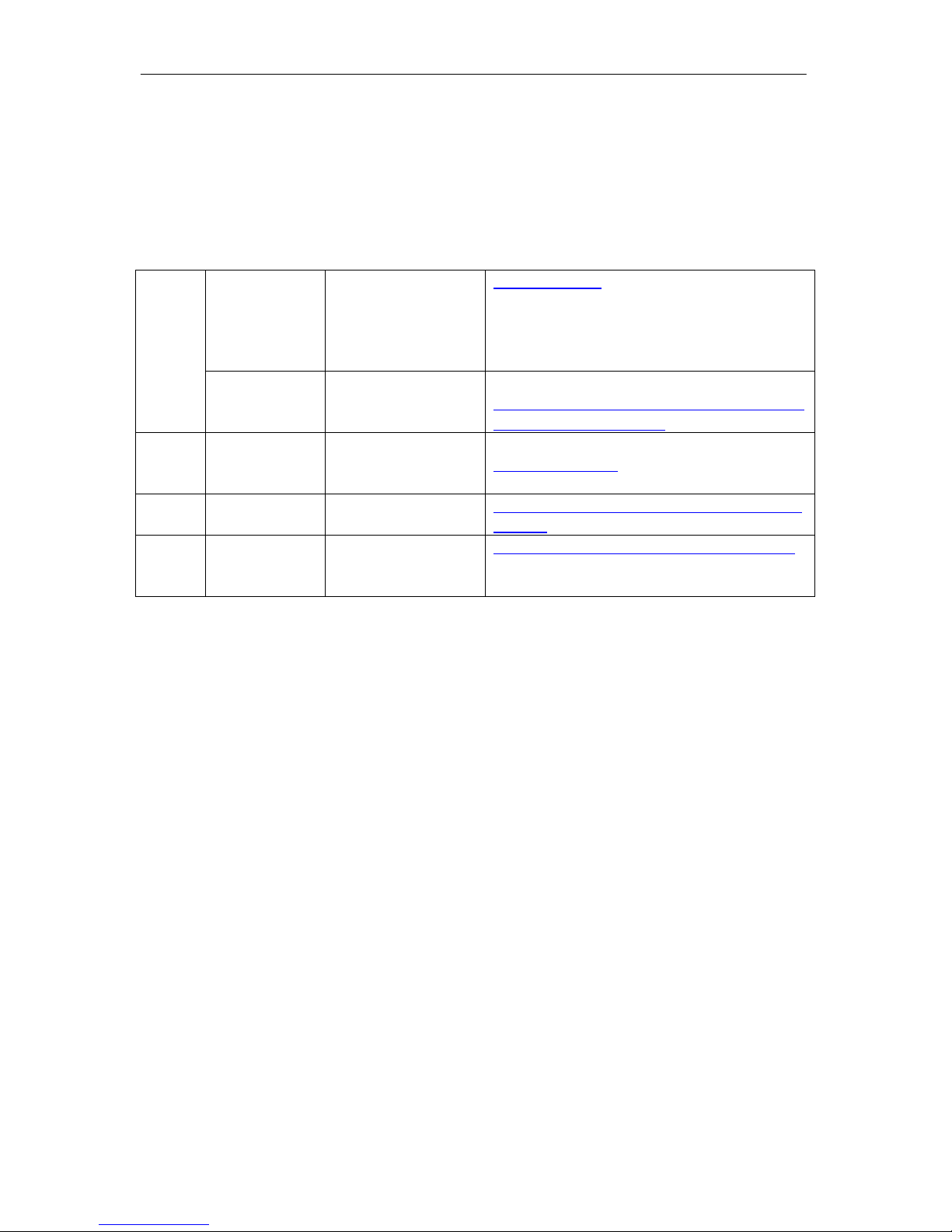
Below follows a list of integrated chipsets, if available the driver location on the CD or the
manufacturer’s website.
Intel
chipset Chipset Intel
852GM + ICH4
I/O Chipset ITE
IT8712
ethernet 82562, 10/100Base On CD or:
Realtek audio AC’97 On CD or:
ELO touchscreen http://elotouch.com/Support/Downloads/def
FTDI USB to
FT2232D http://www.ftdichip.com/Drivers/VCP.htm
RS232
(virtual COM)
www.intel.com , support, dowload, chipsets,
embedded chipsets, low power – 852/855
chipset families
http://downloadcenter.intel.com/Product_Fil
ter.aspx?ProductID=998
www.realtek.com , Downloads, Computer
peripheral ICs, PC audio codecs, Software
ault.asp
5-3
Page 30
Installation
5.3 ChangeMe
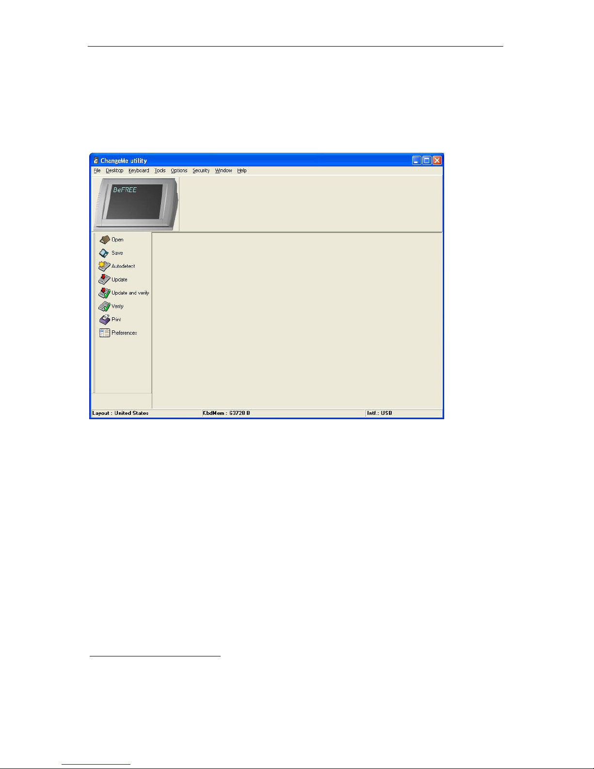
The first time you run ChangeMe, drivers for Tipro USB controller will install automatically.
Let the installation finish, then press “autodetect” to search for the controller.
The next times you run ChangeMe it will detect automatically the controller in BeFREE on
USB1.
Press on the BeFREE icon to open the dialog.
Figure 9 - ChangeMe main window
1
USB is the default interface. Powered BeFREEs can optionally also communicate via serial interface, see 4.1.8
and 5.10.3.
To change the interface in ChangeMe double click on “Intf: USB” in the lower right corner of the main window
(see Figure 9 - ChangeMe main window) and select COM 4, 9600 baud rate.
5-4
Page 31
Installation
5.3.1 Fan control
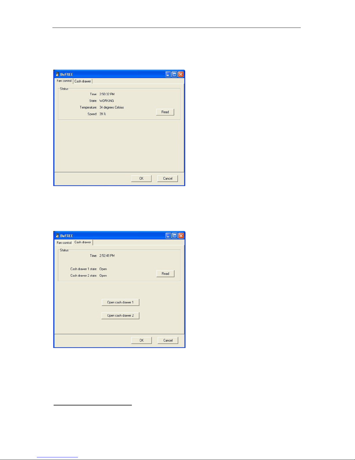
The Fan control window is just for information purposes. Press on “Read” to get the air
temperature inside BeFREE and the relative fanspeed.
Figure 10 - Fan control dialog
5.3.2 Cashdrawer
The Cashdrawer window is used for testing the cashdrawer port.
Although the window is shown for all versions of BeFREE, it functions just for Powered
BeFREEs, which have a cashdrawer port.
Figure 11 - Cashdrawer dialog
Press “Read” to get the current status of the drawer(s). In case no cashdrawer connection is
present (standard and fanless BeFREE) the status open is shown.
On the Powered BeFREE the status is “closed or not connected” when no cashdrawer is
present or when it is connected and closed1. The Status is “open” when the drawer is open.
Use the buttons below to test opening the drawer.
1
Since the connector allows for only one open/close signal, the signal for both drawers is combined. So if either
one of the drawers is open both Drawer 1 and Drawer 2 indicate open.
5-5
Page 32
Installation
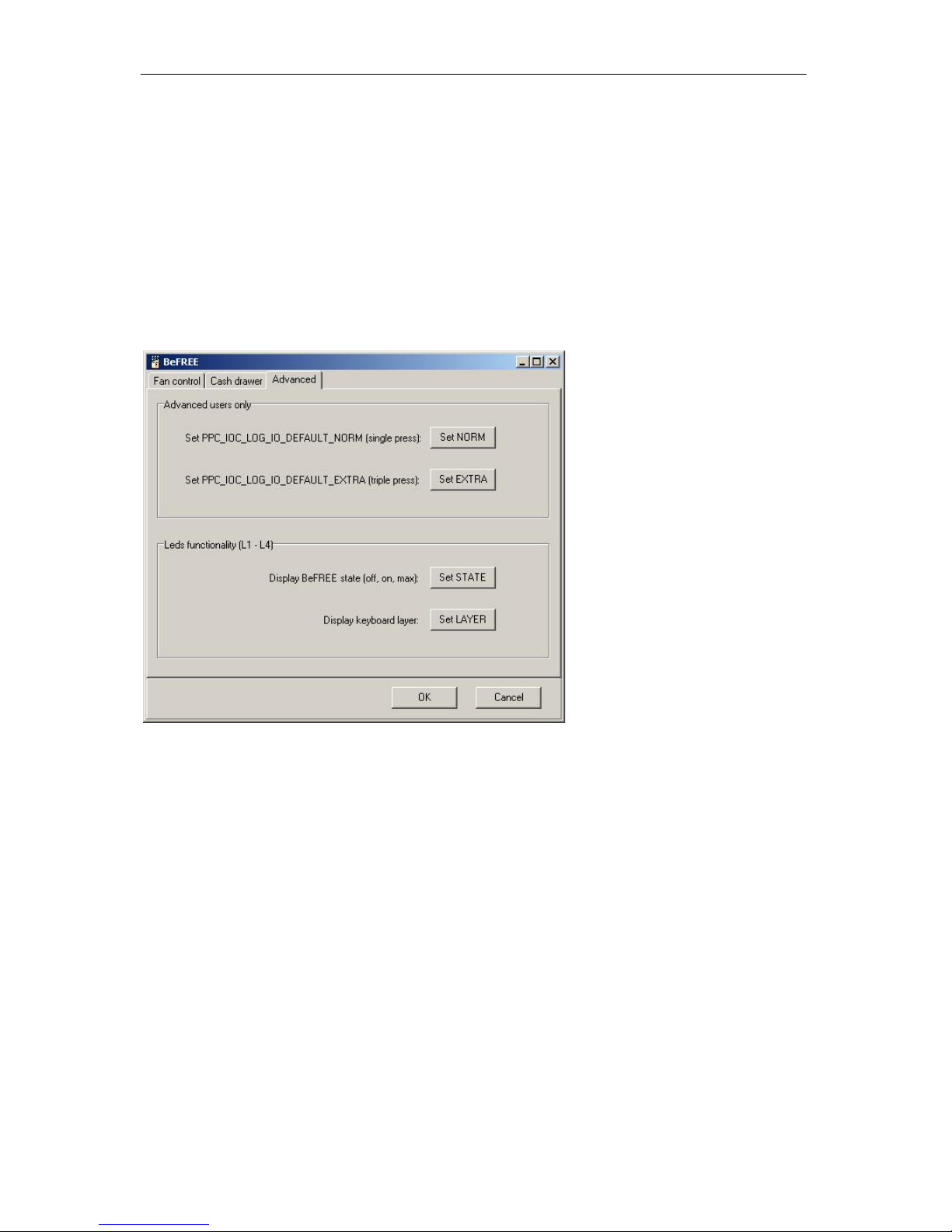
5.3.3 Advanced: ON/OFF
Advanced ON/OFF is a feature to protect the system agains accidental and unauthorised
turning on or off.
To turn the BeFREE on or off when in this mode, the user needs to press the power button 3
times in a fast sequence.
Normally this tab is hidden since there is a risk of not being able to start the BeFREE again if
this is set by mistake.
To show this tab you have to go to ChangeMe’s “debug mode” by pressing the keys
<Ctrl> + <Backspace> at the same time when in the main window. You will see 2 extra menu
items in the menu bar: Extended Tools and Debug.
When you now click on the BeFREE icon again you will see the extra “Advanced” tab.
Figure 12 - Advanced dialog
Set EXTRA sets the Advanced ON/OFF feature.
Set NORM restores the ON/OF configuration to normal, default behavior
Testing
The best is to test this feature before turning off the system!
Set the Advanced ON/OFF by pressing the Set EXTRA button.
Set the Action for the power button to “Ask me what to do”, see below.
Press the power button quickly 3 times in a row. If you have the correct timing, the dialog will
appear asking you if you want to shut down the system. Select Cancel.
Reapeat this a few times to get the correct timimg each time you try.
Another way of protecting the BeFREE from turning off is by disabling the turn off by button
in Windows:
Start > Control Panel > Power Options, Advanced Tab, Power Button;
Change setting to:
• Do nothing - no reaction when the button is pressed. Turn of the BeFREE by going to
Start > Shut Down.
5-6
Page 33
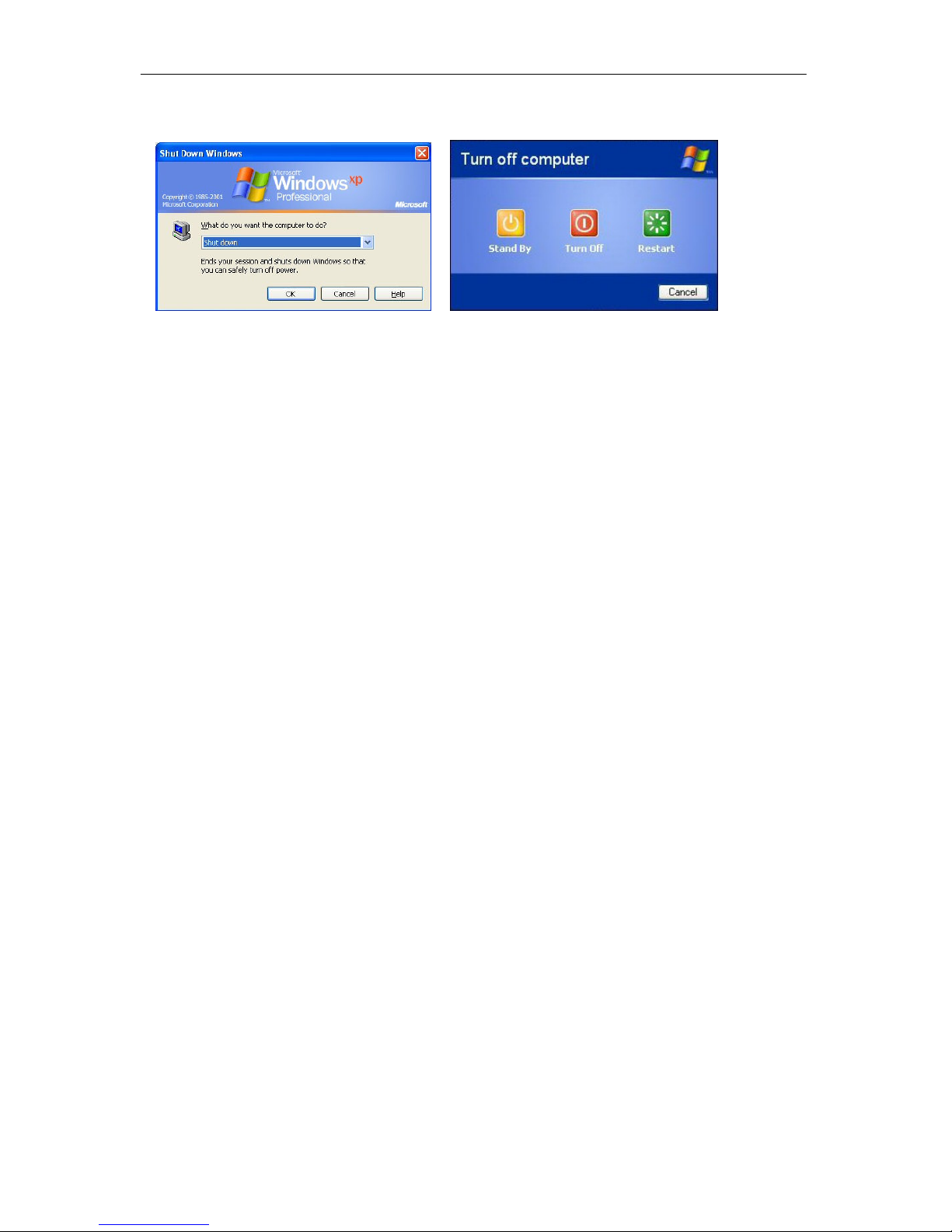
• Ask me what to do – dialog will appear asking you what to do.
Installation
Figure 13 - Shut Down Dialogs
What if things go wrong?
If for some reason you are not able to start the system you will have to open the BeFREE and
set a jumper to bypass the ON/OFF feature. See 5.10.2 for details.
5.3.4 Advanced: LED functionality
To enable the Advanced tab, see 5.3.3 above.
Check Figure 12 - Advanced dialog for reference.
Choose “Set State” to show the fan status on the LEDs L1 – L4, as described in 4.1.9 (default)
Optionally you can also display the current layer of the Tipro controller, as is displayed on
Tipro keyboards. To do this press the button “Set Layer”.
5-7
Page 34
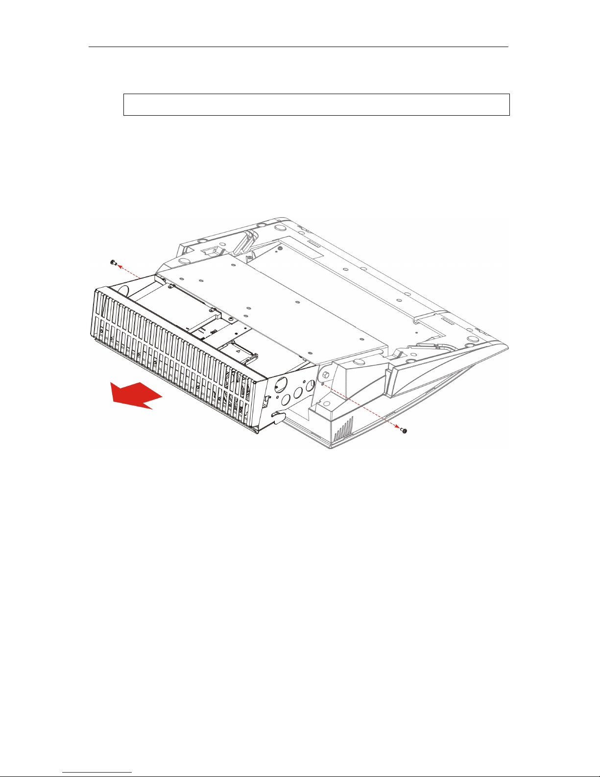
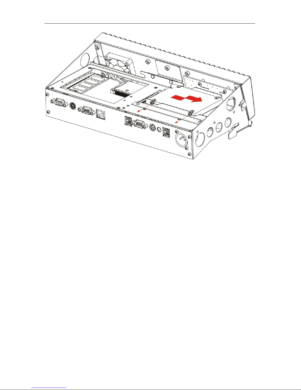
5.4 HOW TO open BeFREE
Always remove the power cord when opening the BeFREE!
Tools:
• philips (cross) screwdriver
Procedure:
1. Remove all connectors from BeFREE
2. Turn BeFREE upside down. Place some soft protection under the screen!
3. Remove the 2 screws on either side of the housing as indicated on the drawing:
Installation
Figure 14 - open BeFREE
4. Now the PC-part can slide out. You might have to push at the connector side and pull at
the heatsink side.
5. Now you can reach the harddisk (see 5.7) and RAM (see 5.8) at the bottom side of the PC-
part.
6. If you turn around the PC-part you can reach the jumpers to set voltage on powered COM
ports (see 5.5)
To close BeFREE again:
7. Slide the PC-part back into the housing
8. Fix the 2 screws at the sides
9. Replace all original cables
5-8
Page 35
Installation
5.5 Setting of the voltage on the powered COM ports
COM 2 (and COM 3 and COM 4 on powered versions) can be configured to have power on
1
pin 9
.
For maximum allowed load see 4.3.2 for standard BeFREE or 4.4.2 for powered BeFREE
• First step is to open the BeFREE. Follow steps described in previous section.
• Next step is to turn around the PC part so that you can see the top.
5.5.1 COM 2
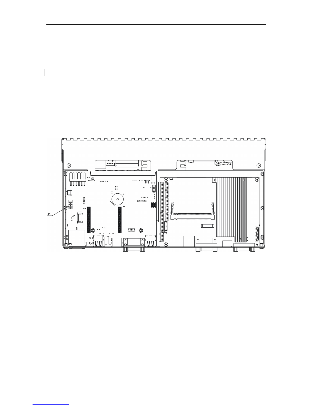
The jumper J1 for COM 2 is positioned totally on the left side, behind the connector for the
power supply, see picture below.
Figure 15 - top view PC-part, standard version
1
See 3.2.5
5-9
Page 36
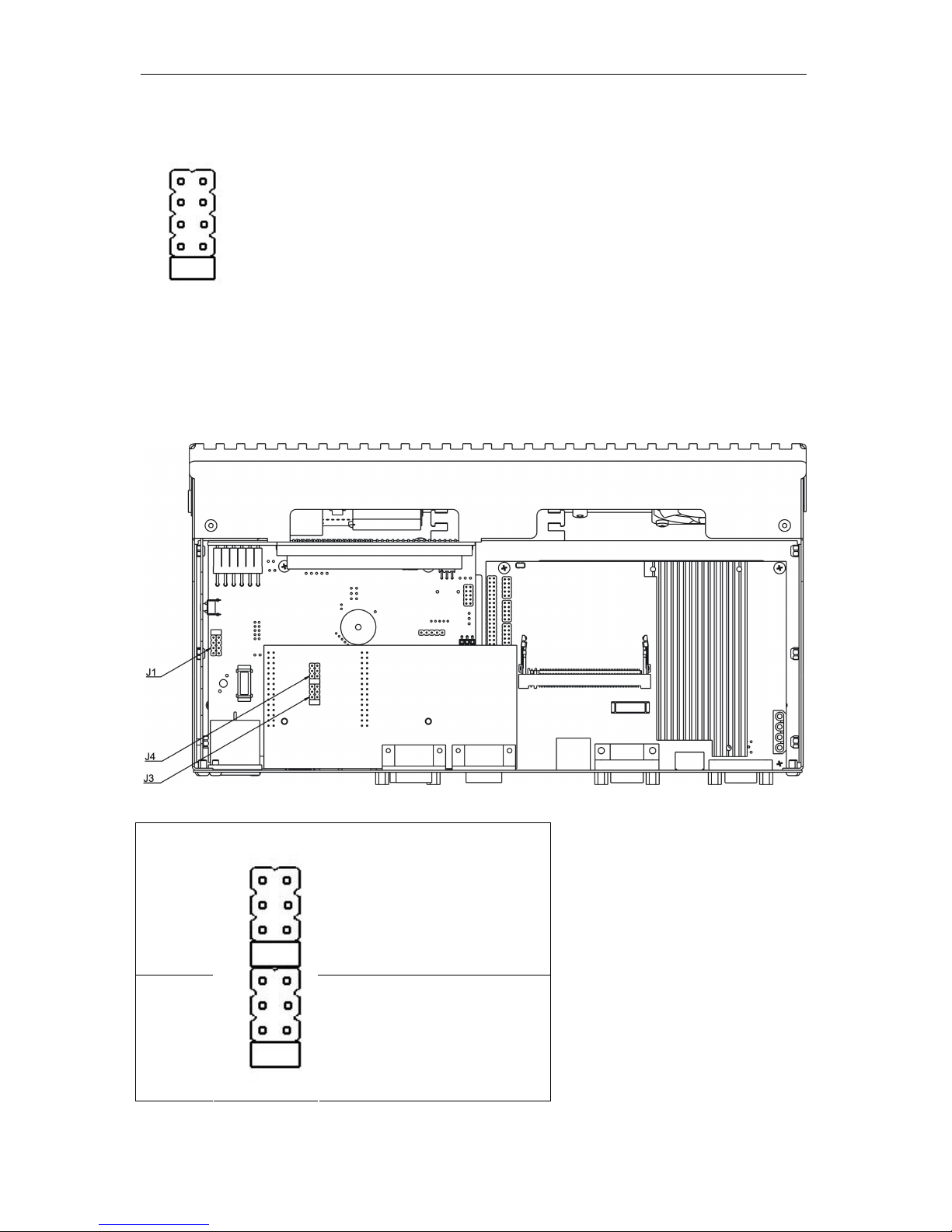
J1, jumper configuring COM 2 pin 9
24V. (just for Powered BeFREE)
12V.
5V.
Not in use
Ring, no power, default
5.5.2 COM3 and COM4
COM 3 and COM 4 are available on Powered BeFREE only.
The jumpers J3 and J4 are located on the Add-on board as indicated below.
Installation
Figure 16 - top view PC-part, Powered version
J3, jumper configuring COM 3 and COM 4 pin 9
COM 4
COM 3
24V.
12V.
5V.
Ring (no power)
24V.
12V.
5V.
Ring (no power)
5-10
Page 37
Installation
1
5.6 Cash drawer jumper setting
Note
: Just Powered version
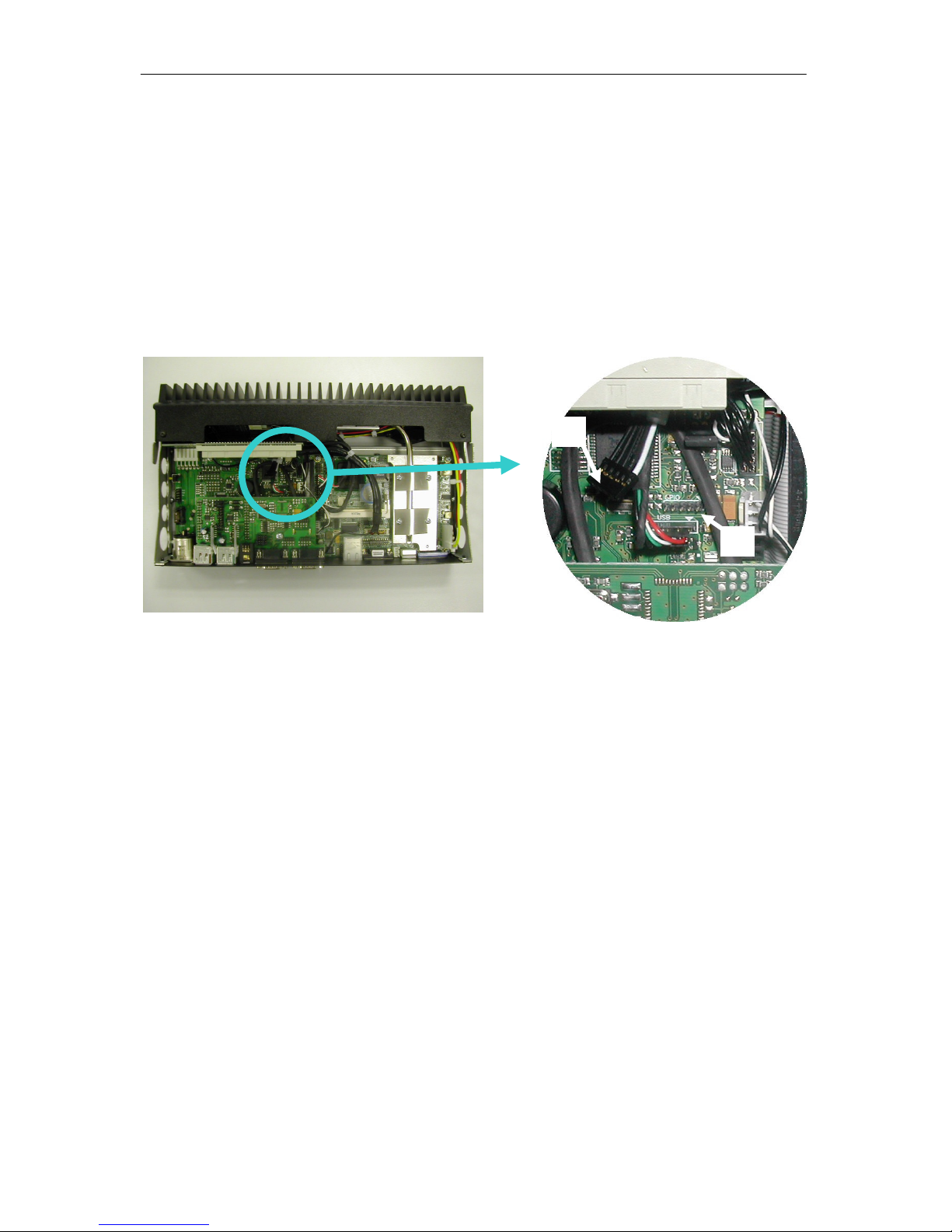
By default this option is disabled, programming through OPOS is default and preferred.
To enable cashdrawer operation through GPIO ports of the compter you must:
• Take PC part of BeFREE out. See section 5.4 for help.
• Connect the cable (no. 1 in the drawing below) to the pin header (no. 2). The white wire
goes to the pin designated with the white arrow. You may have to remove the palstic
cable-wrap that holds the cable.
• Close the BeFREE again.
2
5.7 Replacing Harddisk
Open the BeFREE as described in section 5.4.
The harddisk is positioned at the bottom.
• Release the 2 screws as indicated on the drawing below. Don’t remove them totally, as
they guide the harddisk when sliding out.
• Slide the harddisk as indicated on the picture above, until it comes out of the metal guides.
• Remember how the harddisk is oriented, so you can re-connect the new disk in the same
way.
• Remove the flat cable.
• Now you can connect the flat cable to the new harddisk. Make sure the harddisk is turned
correctly.
• Check if the 2 screws at the rear (near the heatsink) are fixed till the end and the 2 screws
in front are loose enough to slide in the metal guide.
• Slide the harddisk back in position untill it can’t go further.
• Fix the 2 screws in front.
• Slide the PC-part back into the housing.
• Fix the 2 screws at the sides.
5-11
Page 38
Installation
Figure 17 - harddisk
5.8 Replacing RAM
Use only memory modules SODIMM DDR 200 pin 266 MHz. or faster.
Open the BeFREE as described in section 5.4.
The RAM module is positioned at the bottom, near the fan.
• Release the two springs at either side of the module, the module will “pop-up”
• Pull the memory module out in the direction it is already oriented.
• Place the new memory module at an angle, push it till the end. Make sure it oriented
correctly. The cut-out between the contacts must be aligned with the tooth on the
connector.
• Now push it down, until the springs snap into place and hold the module.
• Slide the PC-part back into the housing.
• Fix the 2 screws at the sides.
5.9 Cleaning
You should clean BeFREE’s screen display with dry soft, clean cloth. Then you should wipe
the cloth across the display from left to right, moving from the top of the display down to the
bottom of the display. If your display contains grease or some other contaminant, then you
should dampen your cloth with water.
You should also use some non-aggressive cleaners as:
Water.
Water with a tiny amount of soft liquid soap.
Isopropyl Alcohol.
Commercial glass cleaners that do not contain ammonia.
5-12
Page 39
1 2 3
1 2
3
5.10 Jumpers
Installation
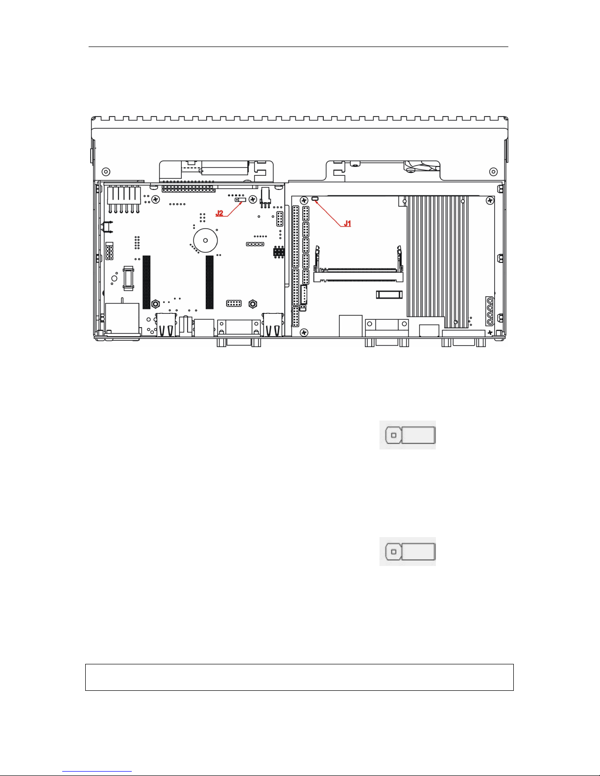
Figure 18 - Jumpers for CMOS and ON/OFF bypass
5.10.1 Clear CMOS
To reset the BIOS to it’ s original -factory- setting place the
jumper J1 (see picture above) for a short time to position 2-3,
after that place it back to it’ s original position 1-2.
Normal position
Close the BeFREE and restart the system.
5.10.2 Bypass ON/OFF logic.
In case the system cannot be started, something might be
wrong with the built-in ON/OFF logic on the Tipro
Controller.
Place the jumper J2 (see Figure 18) to position 2-3 to bypass
Normal position
the logic and connect the ON/OFF button directly to the
mainboard.
Advanced ON/OFF as described in 5.3.3 is disabled in this
case.
Note:
a fault can also happen when a faulty module is connected to BeFREE, or when a module is
wrongly connected via Tipro bus. Verify this first before opening BeFREE
5-13
Page 40
Installation
5 2 3 4
5 2 3 4
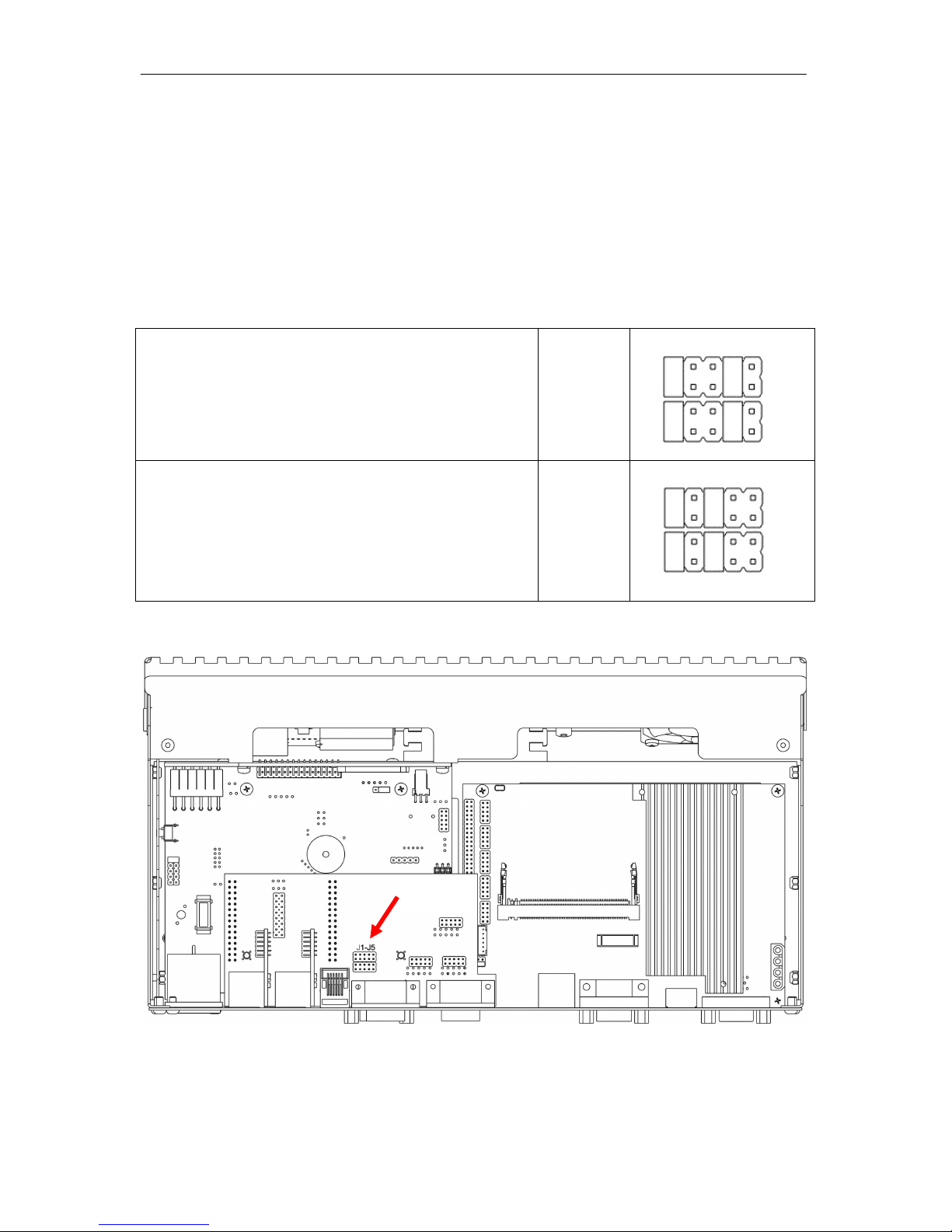
5.10.3 Tipro Controller serial communication
On a Powered BeFREE the Tipro Controller can be set to communicate via COM 4. USB
communication is also still possible.
The connector COM 4 will become useless in this case.
After you open the BeFREE (see 5.4), the jumpers can be found behind COM port 4 (see
Figure 19).
The jumpers must be set in pairs, each position corresponds to 2 jumpers.
To enable the serial controller communication jumper 4 must be moved to 3
• Connector COM port 4 to COM 4
• Tipro controller USB
• Connector COM port 4 not functional
Tipro controller on USB and On COM 4
default
optional
1
1
J1 – J5
Figure 19 - serial communication controller J1 - J5
5-14
Page 41

BIOS settings
6 BIOS settings
Any changes to the BIOS, except changing date/time and boot order, are not recommended by
Tipro and are at the customers own risk1.
You can always recall Tipro default settings by selecting “ Load optimized defaults” in the
main menu (see 6.4 and 6.5).
6.1 System Test and Initialization
These routines test and initialize board hardware. If the routines encounter an error during the
tests, you will either hear a few short beeps or see an error message on the screen. There are
two kinds of errors: fatal and non-fatal. The system can usually continue the boot up sequence
with non-fatal errors. Non-fatal error messages usually appear on the screen along with the
following instructions: Press <F1> to RESUME.
Write down the message and press the F1 key to continue the boot up sequence.
6.2 System configuration verification
These routines check the current system configuration against the values stored in the CMOS
memory. If they do not match, the program outputs an error message. You will then need to
run the BIOS setup program to set the configuration information in memory.
There are two situations in which you will need to change the CMOS settings:
1. You want to change the boot order.
2. The CMOS memory has lost power and the configuration information has been erased.
6.3 Award BIOS Setup
Awards BIOS ROM has a built-in Setup program that allows users to modify the basic system
configuration. This type of information is stored in battery-backed CMOS RAM so that it
retains the Setup information when the power is turned off.
6.4 Entering Setup
Power on the computer and press <Del> immediately when the Tipro logo is shown. This will
allow you to enter Setup
6.5 Main menu
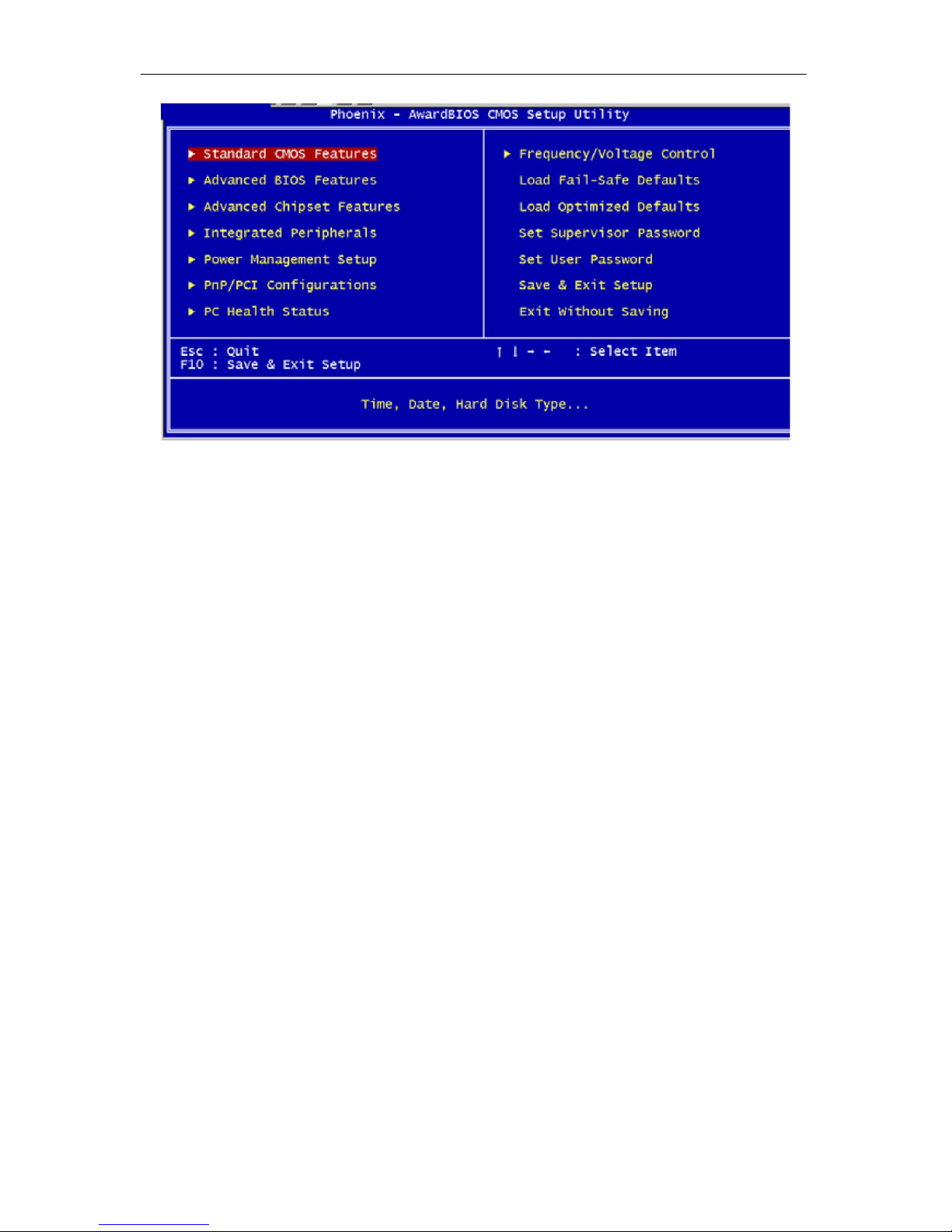
Once you enter the Phoenix - Award BIOS CMOS Setup Utility, the Main Menu will appear
on the screen. The Main Menu allows you to select from several setup functions and two exit
choices. Use the arrow keys to select among the items and press <Enter> to accept and enter
the sub-menu.
1
Any repairs and support that are a consequence of changes to the BIOS, other than date/time or boot order, are
not covered under warranty.
6-1
Page 42
BIOS settings
Note that a brief description of each highlighted selection appears at the bottom of the screen.
6.5.1 Setup Items:
The main menu includes the following main setup categories.
In normal conditions you would need at most to enter (one of ) the following items:
• Standard CMOS Features
Use this menu for basic system configurations, such as time, date etc.
• Advanced BIOS Features
This setup includes all the items of Award special enhanced features.
• Integrated Peripherals
This setup is to specify your settings for integrated peripherals.
• PC Health Status
This entry displays the current status of your PC.
• Load Fail-Safe Defaults
This menu to load the BIOS default values for the minimal/stable performance of your PC
• Load Optimized Defaults
This item to load the default factory settings for BIOS for optimal system performance..
• Set Supervisor / User Password Setting
Change, set, or disable password. It allows you to limit access to the system and Setup, or
just to Setup.
• Save & Exit Setup
Save CMOS value changes to CMOS and exit setup.
• Exit Without Saving
Abandon all CMOS value changes and exit setup.
6-2
Page 43
BIOS settings
6.5.2 STANDARD CMOS FEATURES
6.5.2.1 Date and Time Configuration
The BIOS determines the day of the week from the other date information. This field is for
information only.
Press the left or right arrow key to move to the desired field (date, month, year).
Press the PgUp/- or PgDn/+ key to change the setting, or type the desired value into the field.
The time format is based on the 24-hour military-time clock. For example, 1 p.m. is 13:00:00
hours.
Press the left or right arrow key to move to the desired field. Press the PgUp/- or PgDn/+ key
to increment the setting, or type the desired value into the field.
6.5.2.2 IDE Primary Master
The BIOS supports up to two IDE drives. This section does not show information about other
IDE devices, such as a CD-ROM drive, or other hard drive types, such as SCSI drives.
NOTE:
We recommend that you select type AUTO for all drives. The BIOS can automatically detect
the specifications and optimal operating mode of almost all IDE hard drives. When you select
AUTO
for a hard drive, the BIOS will detect its specifications
In case detailed manual setup is needed, please contact Tipro support for additional
information
6.5.2.3 Halt On
During the power-on-self-test (POST), the computer stops if the BIOS detects a hardware
error. You can tell BIOS to ignore certain errors during POST and continue the boot-up
process.
6.5.3 Advanced BIOS features
Most important in this menu is the boot order.
Select the desired option for first-, second- and third Boot Device.
Note:
For booting from LAN, additionally the LAN boot ROM must be enabled, see 6.5.5.2
6.5.4 Advanced Chipset Features
Leave all settings to default.
Make sure that Boot display is set to CRT+LCD and that the Panel Type(LVDS) is set to
1024x768 24bit.
6.5.5 Integrated Peripherals
6.5.5.1 OnChip IDE Device
Leave All settings to default
6-3
Page 44

6.5.5.2 Onboard Device
USB Controller
[Default: Enabled]
USB 2.0 Controller
[Default: Enabled]
AC97 Audio
[Default: Auto]
Init Display First
OnBoard LAN
[Default: Enabled]
OnBoard LAN Boot ROM
[Default: Disabled]
6.5.5.3 SuperIO Device
OnBoard Serial Port 1 / Serial Port 2
1: [Default: 3F8/IRQ4]
2: [Default: 2F8/IRQ3]
COM2 RS232/422/485 Type
[Default: RS232]
UART Mode Select
[Default: Normal]
BIOS settings
Enable / Disable USB Controller.
Enable / Disable USB 2.0 Controller. High
speed mode will turn on when high speed
device were attached.
Auto Detect / Disable Onboard AC97 Device.
Leave to default setting
If you don't need to use onboard LAN
function, just configure it as "Disabled"
without any efforts
on jumper setting.
To enable booting from LAN
Auto: BIOS will automatically setup the port
address.
3F8/IRQ4: Enable onboard Serial port and
address is 3F8, IRQ set to 4.
2F8/IRQ3: Enable onboard Serial port and
address is 2F8, IRQ set to 3.
3E8/IRQ4: Enable onboard Serial port and
address is 3E8, IRQ set to 4.
2E8/IRQ3: Enable onboard Serial port and
address is 2E8, IRQ set to 3.
Disabled: Disable onboard Serial port.
Select COM2 type if hardware supports
422/485.
Leave to default value
6.5.5.4 Digital I/O Setting
Leave to default settings
6.5.6 Power Management Setup
Leave all to default, except:
PWRON After PWR-Fail
[Default: Disabled]
If enabled the system will automatically
reboot up if it shut down because of power
failure.
6-4
Page 45

BIOS settings
6.5.7 PnP/PCI Configurations
Leave to default settings
6.5.8 PC Health Status
You can set the shutdown temperature of the system. Default this is set to 70oC.
All other values are for information purposes only.
6.5.9 Frequency/Voltage Control
Leave to default values
6.5.10 Load Fail-Safe Defaults
Use this menu to load the BIOS default values for the minimal/stable performance for your
system to operate.
In our case it is also safe to load Optimized Defaults.
6.5.11 Load Optimized Defaults
Use this menu to load the BIOS default values that are factory settings for optimal
performance system operations. In our case this is the same as Load Fail-Safe
6-5
Page 46

7 References:
- BIOS document 8310
- ChangeMe Help
- MIDAPI Help
- FREE Technical specification
References:
7-1
 Loading...