

Page 1
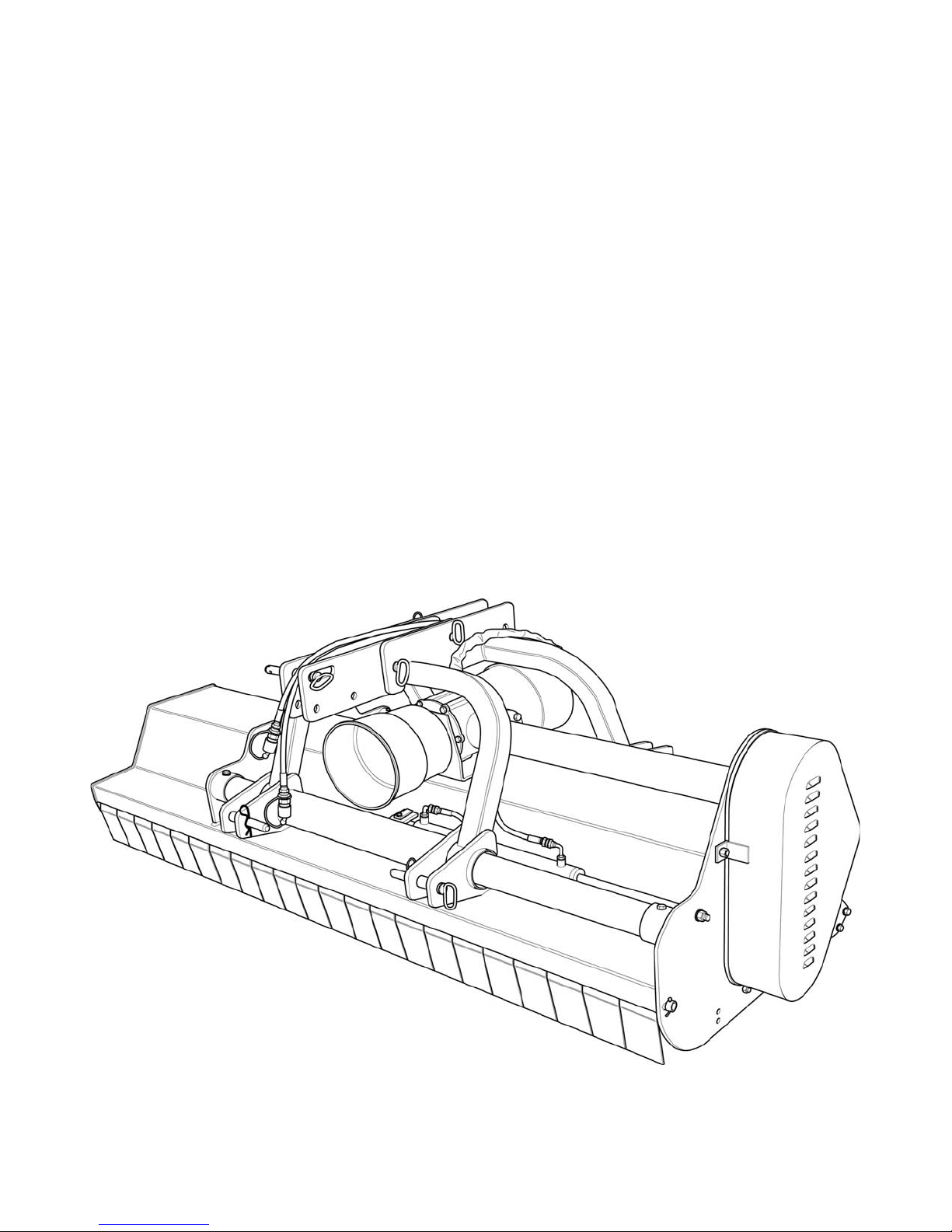
BEFCO®
Operator’s Manual
DESTROYER
Heavy Duty Flail Shredder
D90-060, D90-072, D90-088
The operator’s manual is a technical service guide and must always accompany the machine.
Manual 971-401B
October 2016
Page 2

SAFETY
Take note! This safety alert symbol found throughout this manual is used to call your
attention to instructions involving your personal safety and the safety of others. Failure to
follow these instructions can result in injury or death.
This symbol means:
ATTENTION!
BECOME ALERT!
YOUR SAFETY IS INVOLVED!
Signal Words
Note the use of the signal words DANGER, WARNING and CAUTION with the safety messages. The
appropriate signal words for each have been selected using the following guidelines:
DANGER: Indicates an imminently hazardous situation that, if not avoided, will result in death or
serious injury.
WARNING: Indicates a potentially hazardous situation that, if not avoided, could result in death or
serious injury, and includes hazards that are exposed when guards are removed. It may also be used
to alert against unsafe practices.
CAUTION: Indicates a potentially hazardous situation that, if not avoided, may result in minor or
moderate injury.
Page 3

INDEX
1 - GENERAL INFORMATION
2 - SAFETY PRECAUTIONS
3 - OPERATION
4 - MAINTENANCE
5 - REPAIR PROCEDURES
6 - TROUBLESHOOTING
7 - PRE-DELIVERY CHECKLIST
8 - WARRANTY
PARTS MANUAL
4
41.01 - General
41.02 - Warranty Information
51.03 - Model and Serial Number ID
6
62.01 - Preparation
72.02 - Starting and Stopping
72.03 - Messages and Signs
10
103.01 - Operational Safety
123.02 - Set Up
133.03 - Cutting Height Adjustment
143.04 - Pre-Operational Check
143.05 - Attaching to the Tractor
153.06 - Start Up
163.07 - Working Speed
173.08 - Operating Techniques
183.09 - Hydraulic Side Shift
193.10 - Uneven Terrain
193.11 - Removing Shredder from the Tractor
193.12 - Transport
21
214.01 - Maintenance Safety
224.02 - Service
234.03 - Blade Maintenance
254.04 - Belt Tension
264.05 - Belt Replacement
264.06 - Pulley Alignment
274.07 - Reverse Gearbox Direction
274.08 - Driveline
294.09 - Overrunning Clutch
31
315.01 - Gearbox
315.02 - Pulleys
325.03 - Rotor Shaft
325.04 - Suggested Spare Parts
325.05 - Storage
34
35
36
41
INDEX 3 BEFCO
Page 4

DESTROYER D90 OPERATOR’S MANUAL
1 - GENERAL INFORMATION
Thank you and congratulations for having chosen our implement. Your new flail
shredder is a technologically advanced machine constructed of high quality, sturdy
components that will fulfill your working expectations. Read this manual carefully. It will
instruct you on how to operate and service your shredder safely and correctly. Failure to
do so could result in personal injury and/or in equipment damage.
1.01 - General
The implement described in this manual is to be used with tractors with PTO at 540 rpm
and clockwise rotation.
CAUTION: Always ensure that the coupling of the implement with the tractor is
done at the same PTO speed and direction of rotation. Do not operate this
implement at a PTO speed or direction of rotation other than that shown on the
implement. Serious damage can occur to the machine and/or the operator.
CAUTION: Unless otherwise specified, all hardware is metric. Use only metric
tools on metric hardware. Other tools that do not fit properly can slip and cause
injury.
CAUTION: Right hand and left hand sides of the implement are determined by
facing in the direction the implement will travel when going forward (see fig. 2).
1.02 - Warranty Information
Carefully read the Warranty section1, detailing coverage and limitations of this warranty.
Warranty is provided for customers who operate and maintain their equipment as
described in this manual. Warranty registration is accomplished by the dealer by
completing and forwarding the Warranty Registration form to the Company, along with
a copy of the dealer’s invoice. It is in your best interest to ensure that this has been
done.
Warranty does not cover the following:
1. Cleaning, transporting, mailing and service call charges.
1
GENERAL INFORMATION 4 BEFCO
See Chapter 8 - Warranty.
Page 5

DESTROYER D90 OPERATOR’S MANUAL
2. Normal wear items such as belts, blades, bearings, drivelines, shear pins, slip
clutches, etc.
3. Depreciation or damage caused by normal wear, accidents, improper maintenance,
improper protection or improper use.
4. The use of non-original spare parts and accessories.
Your Authorized Company Dealer has genuine parts in stock. Only these approved
replacement parts should be used.
This limited warranty covers defective material and workmanship. The cost of normal
maintenance or repairs for accidents or improper use and related labor will be borne by
the owner.
1.03 - Model and Serial Number ID
Attached to the frame is an ID plate showing the model and the serial number. Record
your implement model and serial number in the space provided below. Your dealer
needs this information to give you prompt, efficient service when you order parts.
GENERAL INFORMATION 5 BEFCO
Page 6

ESTROYER D90 OPERATOR’S MANUAL
D
2 - SAFETY PRECAUTIONS
Safety is the primary concern in the design and manufacture of our products.
Unfortunately our efforts to provide safe equipment can be wiped out by a single
careless act of an operator.
In addition to the design and configuration of equipment, hazard control and accident
prevention are dependent upon the awareness, concern, prudence and proper training
of personnel involved in the operation, transport, maintenance and storage of
equipment. It is the operator’s responsibility to read and understand all safety and
operating instructions in the manual and to follow these.
Allow only properly trained personnel to operate the shredder. Working with unfamiliar
equipment can lead to careless injuries. Read this manual, and the manual for your
tractor, before assembly or operation, to acquaint yourself with the machines. It is the
shredder owner’s responsibility, if this machine is used by any person other than
yourself, is loaned or rented, to make certain that the operator, prior to operating, reads
and understands the operator’s manuals and is instructed in safe and proper use.
2.01 - Preparation
1. Before operating equipment read and understand the operator’s manual and the
safety signs (see fig. 2).
2. Thoroughly inspect the implement before initial operation to assure that all
packaging materials, i.e. wires, bands, and tape have been removed.
3. Personal protection equipment including hard hat, safety glasses, safety shoes, and
gloves are recommended during assembly, installation, operation, adjustment,
maintaining and/or repairing the implement.
4. Operate the shredder only with a tractor equipped with an approved
Roll-Over-Protective-System (ROPS). Always wear your seat belt. Serious injury or
even death could result from falling off the tractor.
5. Clear area to be cut of stones, branches or other debris that might be thrown,
causing injury or damage.
6. Operate only in daylight or good artificial light.
7. Ensure shredder is properly mounted, adjusted and in good operating condition.
8. Ensure that all safety shielding and safety signs are properly installed and in good
condition.
SAFETY PRECAUTIONS 6 BEFCO
Page 7

ESTROYER D90 OPERATOR’S MANUAL
D
2.02 - Starting and Stopping
1. Be sure that no one is near the machine prior to engaging or while the machine is
working.
2. Be sure the tractor is in “Neutral” before starting engine.
3. Shredder operating power is supplied from tractor PTO. Refer to your tractor manual
for PTO engagement and disengagement instructions. Always operate PTO at 540
rpm. Know how to stop the tractor and shredder quickly in case of an emergency.
4. When engaging PTO, the engine rpm should always be low. Once engaged and
ready to start cutting, raise PTO speed to 540 rpm and maintain throughout cutting
operation.
5. Check the tractor master shield over the PTO stub shaft. Make sure it is in good
condition and fastened securely to the tractor. Purchase a new shield if old shield is
damaged or missing.
6. After striking an obstacle, disengage the PTO, shut the tractor down, wait for all
moving parts to come to a complete stop and thoroughly inspect for damage before
restarting.
7. Never engage the PTO until the shredder is in the down position and resting on the
ground. Never raise the shredder until all blades have come to a complete stop.
8. To park the vehicle safely, stop vehicle on a level surface (not on a slope),
disengage PTO, engage the parking brake, stop the engine, remove the key, and
wait for engine and all moving parts to stop before leaving the operator’s seat.
9. Stay clear of rotating drivelines. Entanglement in rotating driveline can cause serious
injury or death. Wear close fitting clothing. Stop the engine and be sure PTO
driveline is stopped before getting near it.
2.03 - Messages and Signs
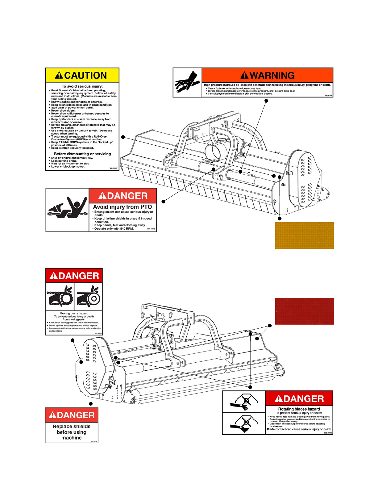
1. Read and adhere to all safety and operating decals on this machine (see fig. 2).
2. Before dismounting tractor: Allow moving parts to stop, stop engine, set brake and
remove the key of unattended equipment.
3. Keep away from rotating blades and driveline.
4. Keep guards and shields in place and in good condition.
5. Do not use with bystanders in area.
6. Allow no riders on tractor or shredder.
7. Allow moving parts to stop before repair.
8. Securely support shredder before working underneath.
Additional warning and operating decals are available at no extra charge. Please specify
model and serial number when ordering.
SAFETY PRECAUTIONS 7 BEFCO
Page 8
ESTROYER D90 OPERATOR’S MANUAL
D
Fig. 2 - Safety decals - implement; replace immediately if damaged.
right side
left side
Yellow reflective decal
(D90-088 only)
Red reflective decal
right side
left side
SAFETY PRECAUTIONS 8 BEFCO
Page 9
ESTROYER D90 OPERATOR’S MANUAL
D
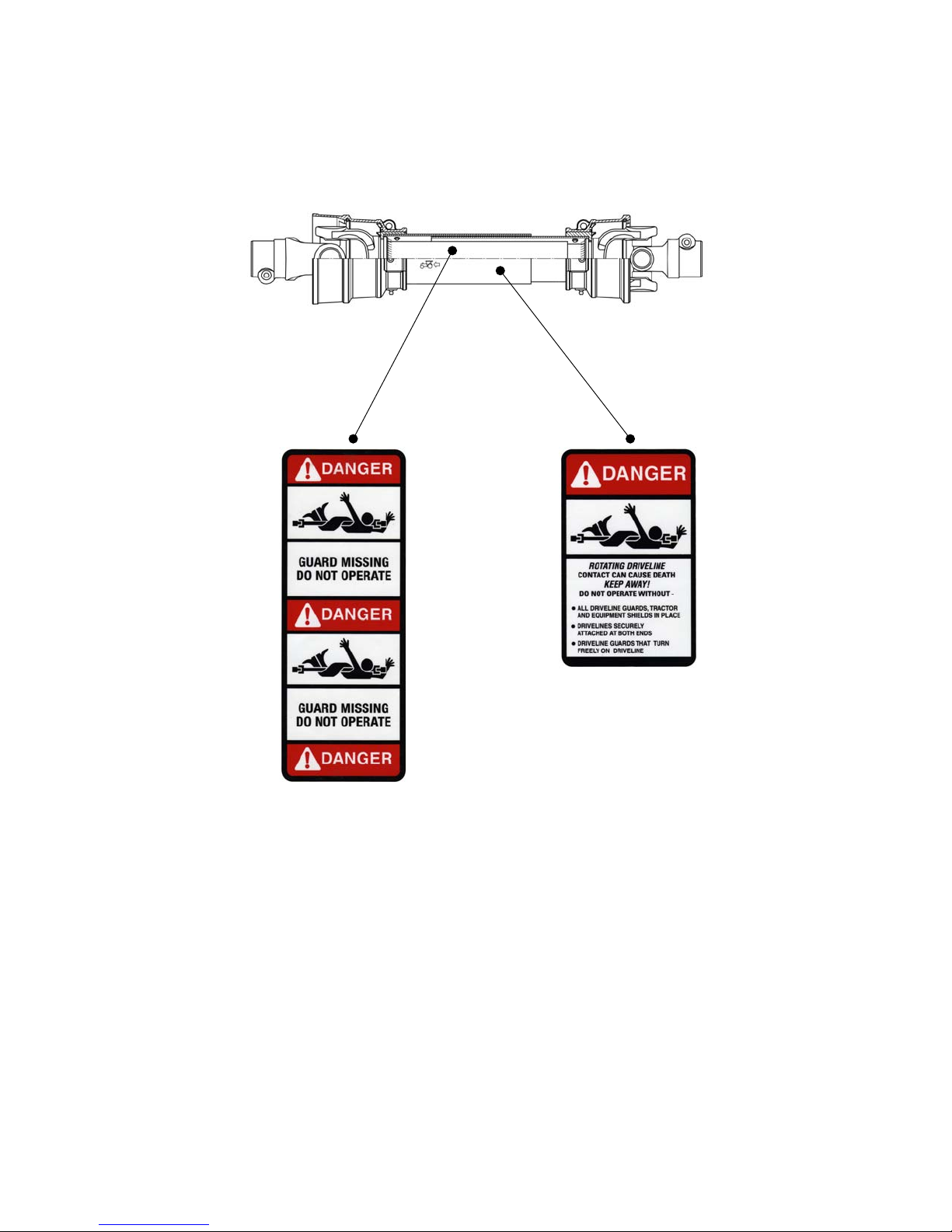
Safety decals - driveline; replace immediately if damaged.
placed on outer tube
placed on outer shield
SAFETY PRECAUTIONS 9 BEFCO
Page 10

ESTROYER D90 OPERATOR’S MANUAL
D
3 - OPERATION
The Destroyer D90 is a sturdy and easy to use flail shredder. It is especially designed to
offer the best performance in cutting and pulverizing corn stalks and other row crops,
heavy grass from set a side fields, tree prunings in orchards, municipal mowing and
wherever professional, accurate and safe shredding are required. Engineered for
tractors from 40 to 90 HP with category 1 or 2 three point hitches (quick hitch
compatible), the D90 is available in 60”, 72” and 88” cutting widths. All models are
equipped with a category 6 driveline with overrunning clutch for 540 rpm PTO’s. Flail
shredders are also equipped with an hydraulic side shift that allows for easy and hassle
free shredding in hard to reach areas such as under tree limbs or near fences.
The hammer type blades turn against the direction of travel and are capable of cutting
material up to 2” in diameter. This cutting motion from bottom to top allows for a cleaner
finish and ensures safety at all times since all the debris from the mower is blown up
and around the rotor of the shredder then straight down to the ground.
Destroyer D90 flail shredders can be either front or rear tractor mounted.
3.01 - Operational Safety
CAUTION: Our shredders are designed considering safety as the most important
aspect and are the safest available in today’s market. Unfortunately, human
carelessness can override the safety features built into our machines. Injury
prevention and work safety, aside from the features on our shredders, are very
much due to the responsible use of the equipment. It must always be operated
prudently following with great care, the safety instructions laid out in this manual.
1. The use of this equipment is subject to certain hazards which cannot be prevented
by mechanical means or product design. All operators of this equipment must read
and understand this entire manual, paying particular attention to safety and
operating instructions, prior to using.
2. Do not operate the tractor and shredder when you are tired, sick or when using
medication.
3. Keep all helpers and bystanders at least 100 yards from a flail shredder. Only
properly trained people should operate this machine.
4. When this machine is operated in populated areas where thrown objects could injure
persons or property, the standard deflector shielding (which is designed to reduce
the possibility of thrown objects) must be installed.
5. The majority of accidents involve entanglements on the driveline, injury of
bystanders by objects thrown by the rotating blades, and operators being knocked
OPERATION 10 BEFCO
Page 11

ESTROYER D90 OPERATOR’S MANUAL
D
off the tractor by low hanging limbs and then being run over by the shredder.
Accidents are most likely to occur with machines that are loaned or rented to
someone who has not read the operator’s manual and is not familiar with a flail
shredder.
6. Always stop the tractor, set brake, shut off the tractor engine, remove the ignition
key, lower implement to the ground and allow shredder blades to come to a
complete stop before dismounting tractor. Never leave equipment unattended with
the tractor running.
7. Never place hands or feet under shredder with tractor engine running or before you
are sure all motion has stopped. Stay clear of all moving parts.
8. Do not allow riders on the shredder or tractor at any time. There is no safe place for
riders.
9. Do not operate unless all personnel, livestock and pets are at least 100 yards away
to prevent injury by thrown objects.
10.Before backing up, disengage the shredder and look behind carefully.
11.Install and secure all guards and shields before starting or operating.
12.Keep hands, feet, hair and clothing away from moving parts.
13.This flail shredder is designed for use only on tractors with 540 rpm power take off.
14. Never operate tractor and shredder under trees with low hanging limbs. Operators
can be knocked off the tractor and then run over by the rotating blades.
15. The rotating parts of this machine have been designed and tested for rugged use.
However, they could fail upon impact with heavy, solid objects such as steel guard
rails and concrete abutments. Such impact could cause the broken objects to be
thrown outward at very high velocities. To reduce the possibility of property damage,
serious injury, or even death, never allow the cutting blades to contact such
obstacles.
16. Frequently check shredder blades. They should be sharp, free of nicks and cracks
and securely fastened.
17.Stop shredder immediately upon striking an obstruction. Turn engine off, remove
key, inspect and repair any damage before resuming operation.
18. Stay alert for holes, rocks and roots in the terrain and other hidden hazards. Keep
away from drop-offs.
19.Use extreme care and maintain minimum ground speed when transporting on
hillside, over rough ground and when operating close to ditches or fences. Be careful
when turning sharp corners.
20. Reduce speed on slopes and sharp turns to minimize tipping or loss of control. Be
careful when changing directions on slopes. Do not start or stop suddenly on slopes.
Avoid operation on steep slopes.
21. When using a unit, a minimum 20% of tractor and equipment weight must be on
tractor front wheels. Without this weight, tractor could tip over, causing personal
injury or death. The weight may be attained with a front end loader, front wheel
weights, ballast in tires or front tractor weights. When attaining a minimum 20% of
tractor and equipment weight on the front wheels, you must not exceed the ROPS
weight certification. Weigh the tractor and equipment. Do not guess or estimate!
OPERATION 11 BEFCO
Page 12
ESTROYER D90 OPERATOR’S MANUAL
D
22. Inspect the entire machine periodically2. Look for loose fasteners, worn or broken
parts, and leaky or loose fittings.
23. Use only the driveline supplied with the shredder. Do not use it if it is missing any
shield or safety protection.
24. Pass diagonally through sharp dips and avoid sharp drops to prevent “hanging up”
tractor and shredder.
25.Avoid sudden starts and stops while traveling up or downhill.
26. Always cut down slopes; never across the face. Avoid operation on steep slopes.
Slow down on sharp turns and slopes to prevent tipping and/or loss of control.
3.02 - Set Up
Notice to dealer: Pre-delivery setup and service including lubrication is the
responsibility of the authorized dealer. It is up to him to assure that the machine is in
perfect condition and ready to be used. It is his responsibility to ensure that the
customer is aware of all safety aspects and operational procedures for the shredder. He
must also fill out the Pre-Delivery Checklist3 prior to delivering the shredder.
CAUTION: Stand clear of bands when cutting as they could be under sufficient
tension to cause them to fly loose. Take care in removing bands and wire, they
often have extremely sharp edges and cut very easily.
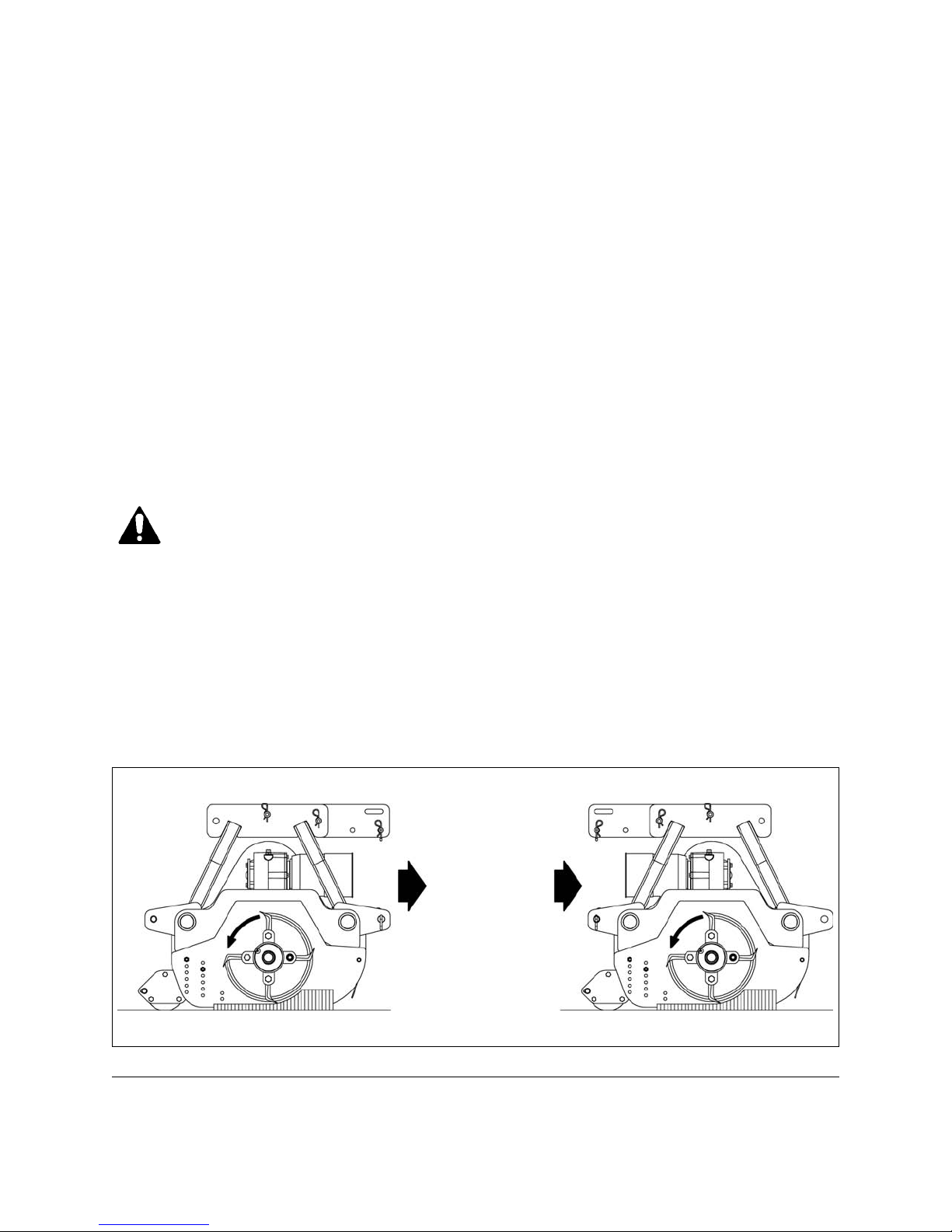
Flail shredders may be either front or rear mounted to the tractor. Front mounting
application requires a tractor that is equipped with a forward PTO and three point hitch.
Setting up the shredder for a front mount application can easily be done at an
Authorized Company Dealership and is accomplished by turning the three point hitch
and the gearbox 180° (see fig. 3).
Fig. 3
Counter clockwise rotor rotation
rear mounted front mounted
2
3
OPERATION 12 BEFCO
See Chapter 4 - Maintenance.
See Chapter 7 - Pre-Delivery Checklist.
Page 13
ESTROYER D90 OPERATOR’S MANUAL
D
3.03 - Cutting Height Adjustment
WARNING: Keep hands and feet away from moving blades.
Be sure tractor engine is off, parking brake is locked, and key is removed before
making any adjustments.
Never rely on the tractor lift system. Install blocks or stands under the shredder
deck to prevent it from falling.
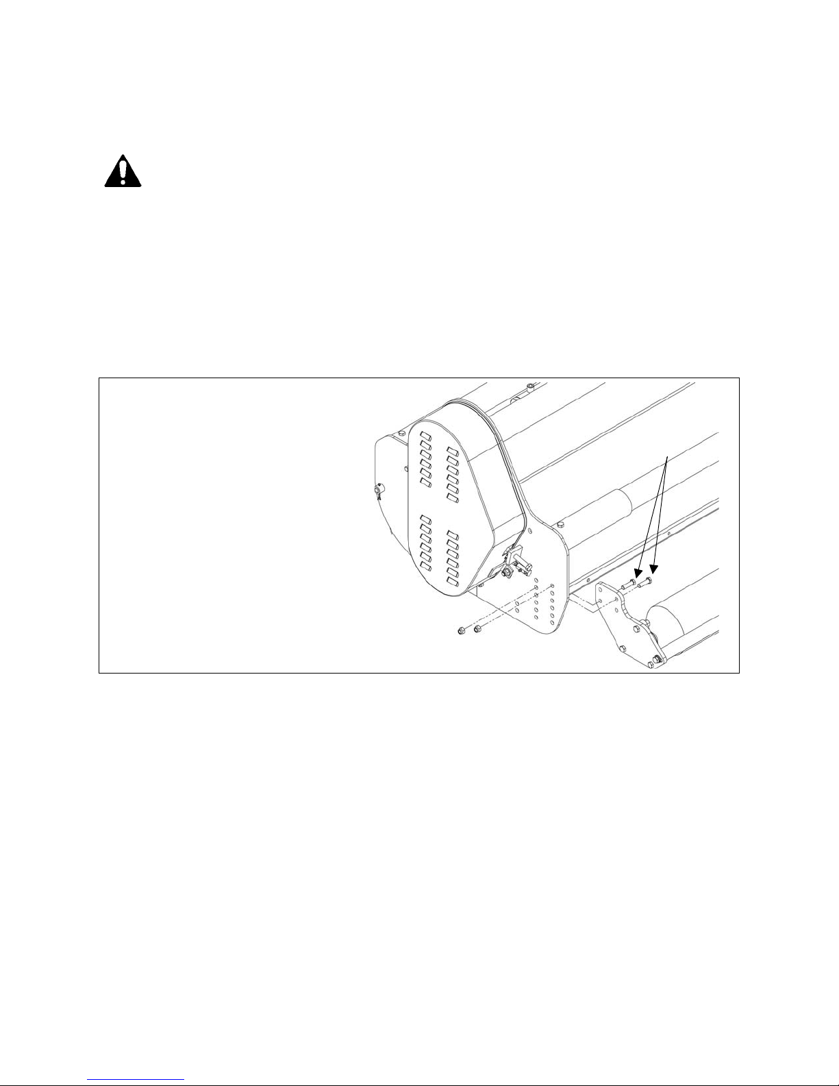
The cutting height is the distance from the blades to the ground. It is changed by
adjusting the position of the rear roller (see fig. 4). All shredders are equipped with a
roller scraper that helps keep the roller clean and the cutting height consistent.
1
Fig. 4
The cutting height changes
by adjusting the position of
the rear roller.
The machine has 9 different cutting height positions. The cutting height is
adjustable from ¾” to 5” in approximately ½” increments. Cutting lower than 2”
under most circumstances should be avoided. Make sure blades do not touch the
ground. Blades that contact the ground will wear out faster and may cause excessive
vibration to the rotor.
To change the cutting height do the following (see fig. 4):
1. Unbolt and remove the 4 bolts, 2 on each side, (see #1, fig. 4) that secure the roller
height position.
2. Move the roller into its desired position and insert the bolts into two of the available
holes. Tighten all 4 bolts. Assembling the roller to the lower holes will increase
cutting height while assembling the roller to the higher holes will reduce cutting
height.
OPERATION 13 BEFCO
Page 14

ESTROYER D90 OPERATOR’S MANUAL
D
3. Ensure the left and right roller brackets are in the same hole position in order to
maintain a level roller which is parallel to the ground. Be sure the shredder is level
and lock the tractor arms so they will not float down or up when cutting.
IMPORTANT: Very low cutting heights should be avoided. Damaging shock loads
occur when the blades strike the ground repeatedly. This can cause damage to
the flail shredder.
3.04 - Pre-Operational Check
IMPORTANT: Check each of the following, carefully, prior to engaging the equipment:
1. The rotor and roller bearings have been greased.
2. The oil in the gearbox.
3. The driveline cross and bearings have been greased.
4. No wrappings or foreign objects are around the blades, belts or driveline.
5. The blades are properly installed and the blade bolts properly torqued
6. All hardware is tight.
7. The tractor, to ensure correct direction of PTO and rpm speed.
8. All safety shields and guards are in place and tightly attached.
9. No people or animals are in the work area.
10. When working, make sure the tractor hitch is locked in position so the front of the
flail shredder will not float down while shredding.
4
.
DANGER: Stay clear of rotating driveline. Entanglement in rotating driveline can
cause serious injury. Disengage PTO, wait for all moving parts to come to a
complete stop, engage parking brake or place transmission in “Park”, shut off the
tractor and remove the key before working around hitch, attaching or detaching
driveline, making adjustments, servicing or cleaning the machine.
3.05 - Attaching to the Tractor
Unit may be used on tractors ranging from 40 to 90 HP equipped with a standard PTO
and a category 1 or 2 three point hitch. Never use this shredder with tractors over 90
HP.
CAUTION: Check the tractor PTO rpm to ensure it is set at 540 and turns
clockwise.
4
5
See Table 1, page 30.
See Table 2, page 30.
5
OPERATION 14 BEFCO
Page 15

ESTROYER D90 OPERATOR’S MANUAL
D
CAUTION: Never attempt to attach the shredder to the tractor or make any
adjustments to it without first turning the tractor off.
DANGER: Failure to ensure a secure coupling of the implement to the tractor can
cause injury and damage to the implement or tractor. If necessary, wheel weights,
front tractor weights and/or tire ballast should be used to improve stability. Be
sure that the tractor tire pressure is correct. It is important to strictly follow the
safety guidelines and instructions laid out in the tractor operator’s manual.
To attach the shredder to the tractor do the following:
1. Back the tractor up to the shredder in order to slip the tractor hitch arms over the
hitch pins on the shredder hitch arms. Turn off the tractor engine. Secure them in
place with the lynch pins.
2. Adjust the tractor sway blocks or chains to remove all side movement.
3. Attach the top link. Adjust tractor top link to allow the shredder, in the working
position, to remain as level as possible with respect to the ground.
4. Install the shielded driveline to the tractor by first lining up the splines and
depressing the snap pin. Push the yoke onto the PTO shaft as far as it will go.
Release the pin and pull back slowly until the pin clicks in place. Repeat this
operation on the implement end. Be sure to install the overrunning clutch side of the
PTO shaft on the implement.
5. Attach the driveline chains to the tractor and to the shredder to keep the driveline
protection from turning. The chains should not be too tight.
6. Ensure the driveline has at least 2” from bottoming out in its shortest working
position and has the minimum 6” overlap in its longest working position. Refer to
Section 4.086 of this manual, if it is determined that the driveline is too long and
needs to be shortened. Contact your Authorized Company Dealer if it is determined
that the driveline is too short for your tractor.
DANGER: The shredder must always be lowered to the ground before starting
tractor engine or engaging PTO lever.
Lower shredder to the ground with the tractor rock shaft control lever until the roller is on
the ground and the shredder frame is parallel to the ground. Lock the tractor rock shaft
6
procedures for shortening the driveline.
OPERATION 15 BEFCO
See Section 4.08 - Driveline, for instructions on how to determine correct driveline length and
3.06 - Start Up
Page 16

ESTROYER D90 OPERATOR’S MANUAL
D
control lever in this position. With the engine idling, slowly engage the PTO drive. Move
the throttle lever gradually until the PTO speed indicated on the shredder is obtained.
The shredder is designed for a PTO speed of 540 rpm.
Shift the transmission to a slow speed gear and start forward, increase the ground
speed by shifting upward until the desired speed is obtained. Do not mow in reverse
unless absolutely necessary and only after careful observation of the area behind the
shredder.
CAUTION: Do not operate this shredder at a PTO speed or direction of rotation
other than that shown on the shredder. Serious damage can occur to the machine
and/or the operator.
Before starting to mow, never forget that the operator is responsible for the following:
1. Safe and correct driving of the tractor and shredder.
2. To learn precise safe operating procedures for both the tractor and the shredder.
3. To ensure all maintenance and lubrication has been performed on the shredder.
4. To have read and understood all safety aspects for the shredder in the operator’s
manual.
5. To have read and understood all safety decals on the shredder.
6. Checking the condition of the blades. Worn or damaged blades should be changed
before starting7.
7. Checking to ensure that the cutting edge is the leading edge of the blade8.
8. Checking that there is no wire, weed, grass or other material wrapped around
blades.
9. Checking to see if front weights need to be added to the tractor in order to maintain
balance.
10. Checking the tractor tires for the proper pressure in accordance with the tractor’s
operator’s manual.
11. Checking that the PTO shield, belt shield, front deflector shields and all other
shielding are on the machine and securely in place.
12.Making sure the proper attire is worn. Avoiding loose fitting clothing which can
become entangled. Wearing sturdy, tough-soled work shoes and protective
equipment for eyes, hands, ears and head. Never operate tractor or implements in
bare feet, sandals or sneakers.
13.Checking area for stones, branches and other debris that might be thrown.
14.Ensuring proper lighting is available, sunlight or good artificial lighting.
The shredding speed depends on ground conditions, tractor HP, shredding height, and
material thickness. Under most conditions a 1 to 4 mph ground speed is best. When
mowing in areas with thick prunings of up to 2” in diameter, it is advisable to operate the
7
8
OPERATION 16 BEFCO
See Section 4.03 - Blade Maintenance.
See Section 4.03 - Blade Maintenance.
3.07 - Working Speed
Page 17

ESTROYER D90 OPERATOR’S MANUAL
D
machine at a speed of 1 mph. When mowing light grass, a speed of approximately 4
mph will work best. Only a test run will enable you to gauge the optimal working speed
for your conditions. As a rule of thumb, and if the conditions permit, grass dispersion is
increased by higher ground speeds.
In order to obtain the best cut possible, always keep the tractor rpm up to the speed
indicated on the shredder. When increasing or decreasing shredding ground speed,
always use gear selection, not engine speed. This will maintain the constant maximum
blade speed necessary for a clean cut.
CAUTION: Do not operate this shredder faster than 6 mph. Serious damage can
occur to the machine and/or the operator.
3.08 - Operating Techniques
All of the following factors are important in selecting the proper forward speed:
1. Height of grass.
2. Type of grass.
3. Density of grass.
4. Type of terrain.
5. Grass condition, wet or dry.
For the best results, try cutting the grass at least once per week during growing season.
Tall, dense grass should be cut at low speed, while thin medium grass can be cut at a
faster ground speed.
Always operate PTO at 540 rpm. This is necessary to maintain proper blade speed and
obtain a clean cut.
Under certain conditions, tractor tires may roll some grass down and prevent it from
being cut at the same height as the surrounding area. If this occurs reduce the tractor
ground speed but maintain a 540 rpm engine speed. The lower ground speed will permit
the grass to at least partially rebound. Under some conditions grass will not rebound
enough to be cut even, resulting in an uneven appearance. In general, lower cutting
height gives a more even cut with less tendency to leave tire tracks. If cut is still not
satisfactory, cut the area twice.
Mow extremely tall grass twice. On the first pass use a high cutting height. On the
second pass, position the shredder at the desired height and, when practical, mow at a
right angle of travel to the first pass.
Plan your pattern to travel straight forward whenever possible.
It is better to cut grass more often, than too short. Short grass deteriorates rapidly in hot
weather and invites weed growth during growing season.
If at any time the shredder should jam resulting in belt slippage of 2 or more seconds,
raise the shredder and continue for 2-3 minutes. This will allow the pulleys to cool and
prolong belt life.
OPERATION 17 BEFCO
Page 18
ESTROYER D90 OPERATOR’S MANUAL
D
DANGER: Never operate the shredder without first ensuring that all protective
devices are properly installed. The shredder blades can throw objects 100 yards
or more which could result in personal or property damage.
Pick up all rocks and other debris before shredding. Enter new areas carefully.
Cut grass higher at first, allowing shredder to clear hidden objects.
CAUTION: For emergency reasons learn how to stop the tractor and shredder
quickly. On the flail shredders always disengage the PTO, lock parking brake,
stop engine and allow the shredder blades to come to a complete stop before
dismounting the tractor.
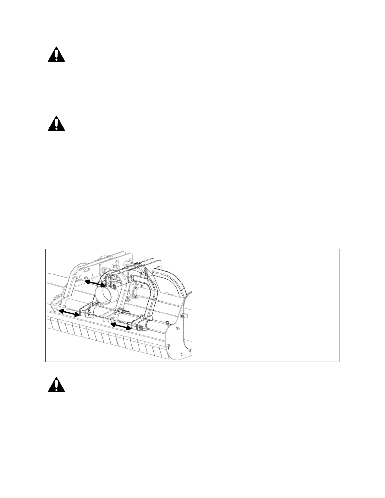
3.09 - Hydraulic Side Shift
D90 flail shredders can be offset to facilitate mowing closer to fences or under tree
limbs. A double action hydraulic cylinder allows the 60” unit to be offset up to 12” to the
right while the 72” and 88” units can be offset up to 16”. Two hydraulic remotes are
required on the tractor to side shift the shredder left and right.
Fig. 5
Hydraulic side shift
12" offset on 60" shredder
16" offset on 72" & 88" shredders
WARNING: High pressure hydraulic oil leaks can penetrate skin resulting in
injury, gangrene or death. Be sure to relieve any hydraulic oil pressure before
disconnecting any lines or pipes between shredder and tractor hydraulic system.
Check for oil leaks using a cardboard, never use hands.
OPERATION 18 BEFCO
Page 19

ESTROYER D90 OPERATOR’S MANUAL
D
3.10 - Uneven Terrain
DANGER: Be careful of rollover when operating tractor and shredder over uneven
ground.
The following precautions should always be observed when working on uneven terrain:
1. In extremely uneven terrain rear wheel weights, front tractor weights, and/or tire
ballast should be used to improve stability.
2. Observe the type of terrain and develop a safe working pattern.
3. Whenever traction or stability is doubtful, first test drive over the terrain with the PTO
disengaged.
4. Operate the implement up and down steep slopes, not across slopes, to prevent the
tractor from tipping. Avoid sudden stops and starts, and slow down before changing
directions on a slope.
5. Pass diagonally through sharp dips and avoid sharp drops to prevent hanging up the
tractor and implement.
6. Slow down on sharp turns and slopes to prevent tipping or loss of control.
7. Avoid tipping the shredder while cutting.
8. Watch for holes, roots or other hidden objects. Do not use near the edge of a gully,
ditch or stream bank.
3.11 - Removing Shredder from the Tractor
CAUTION: Disengage tractor PTO. Set parking brake. Stop engine and remove
key from ignition. Disconnect shredder driveline from tractor PTO shaft. Collapse
driveline and store in appropriate place. Disconnect three point linkage and
carefully drive tractor away from shredder.
3.12 - Transport
CAUTION: Make sure PTO is disengaged and blades have stopped turning before
raising shredder to full transport position. Do not tow tractor and shredder
behind other vehicles. Use a properly equipped trailer with heavy tie-downs for
towing operations.
Before transporting:
1. Always select a safe ground speed that is appropriate for the terrain.
OPERATION 19 BEFCO
Page 20

ESTROYER D90 OPERATOR’S MANUAL
D
2. Beware of traffic on public roads. Install a SMV (Slow Moving Vehicle) sign when
traveling on roads or streets. Comply with all federal, state and local laws.
3. Reduce ground speed when turning and take care that the implement does not strike
obstacles such as trees, fences or buildings.
4. Always disengage PTO before raising the implement to transport position.
5. When raising the shredder be sure the PTO driveline does not hit either the shredder
or the tractor.
6. During transport the shredder should not be lifted over 14”-16” from the ground.
OPERATION 20 BEFCO
Page 21

ESTROYER D90 OPERATOR’S MANUAL
D
4 - MAINTENANCE
DANGER: Stop engine, lock parking brake and remove key before performing any
service or maintenance.
Never rely on the tractor lift system. Install blocks or stands under the shredder
to prevent it from falling.
Always use personal protection devices, such as glasses or gloves when
performing maintenance.
Keep fingers out of slots to prevent injury.
4.01 - Maintenance Safety
1. Good maintenance is your responsibility.
2. Keep service area clean and dry. Be sure electrical outlets and tools are properly
grounded. Use adequate light for the job at hand.
3. Make sure there is plenty of ventilation. Never operate the engine of the towing
vehicle in a closed building. The exhaust fumes may cause asphyxiation.
4. Make no repair or adjustments with the tractor engine running. Before working on
the machine, disengage the PTO, shut off the engine, set the brakes, and remove
the ignition key.
5. Be certain all moving parts on attachment have come to a complete stop before
attempting to perform maintenance.
6. Never work under equipment unless it is blocked securely.
7. Always use personal protection devices such as eye, hand and hearing protectors,
when performing any service or maintenance.
8. Frequently check shredder blades. They should be sharp, free of nicks and cracks
and securely fastened.
9. Periodically tighten all bolts, nuts and screws and check that all cotter pins are
properly installed to ensure unit is in a safe condition.
10. When completing a maintenance or service function, make sure all safety shields
and devices are installed before placing unit in service.
11.After servicing, be sure all tools, parts and service equipment are removed.
12. Never replace hex bolts with less than grade five bolts unless otherwise specified,
9
i.e. shear bolts
.
13.Where replacement parts are necessary for periodic maintenance and servicing,
genuine replacement parts must be used to restore your equipment to original
9
MAINTENANCE 21 BEFCO
Refer to Table 1 - Torque Specifications, page 30.
Page 22
ESTROYER D90 OPERATOR’S MANUAL
D
specifications. The Company will not claim responsibility for use of unapproved parts
and/or accessories and any other damages as a result of their use.
14. Unauthorized modifications to the machine may impair the function and/or safety of
the machine and reduce its life. If equipment has been altered in any way from
original design, the manufacturer does not accept any liability for injury or warranty.
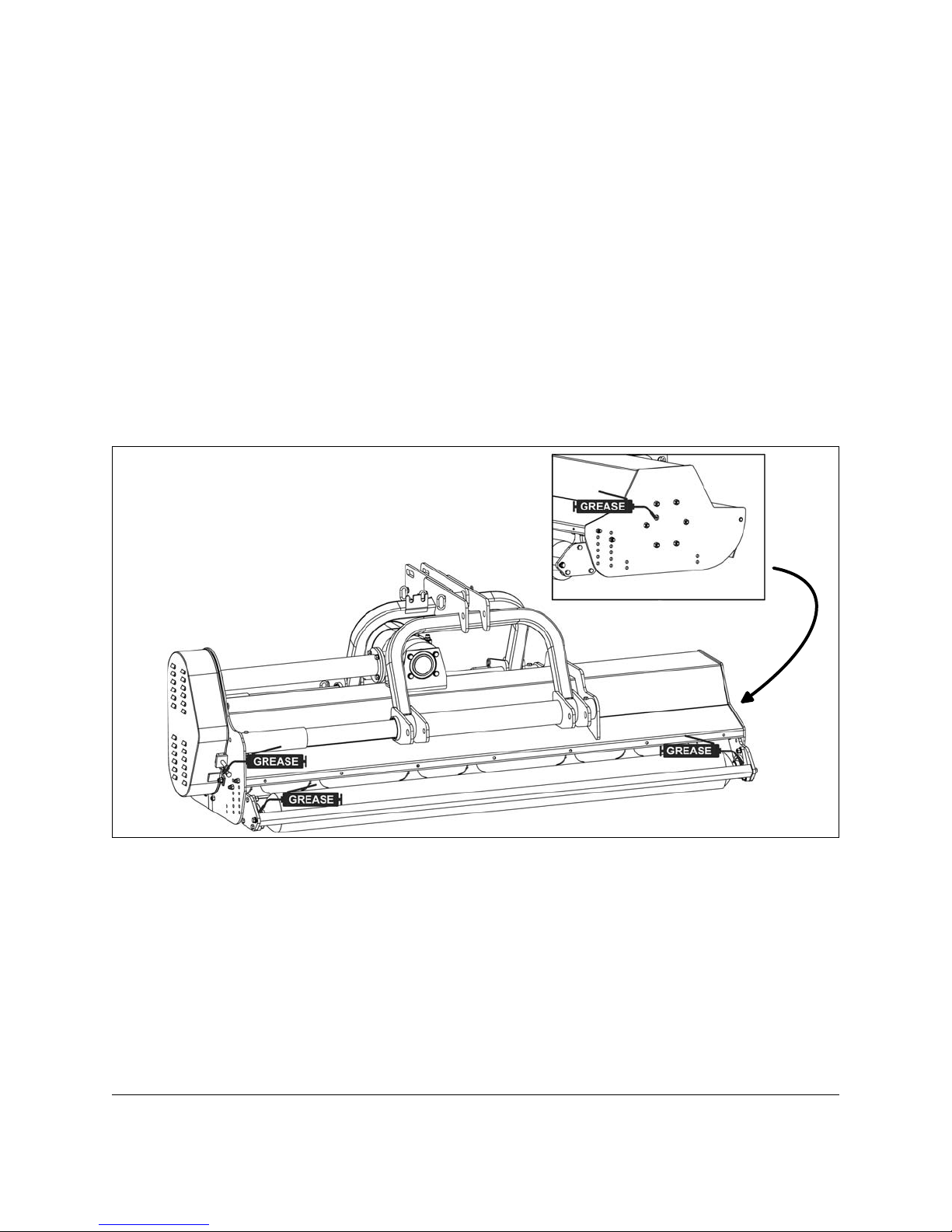
4.02 - Service
The accompanying illustrations show lubrication points. The chart gives the frequency of
lubrication in hours, based on normal operating conditions. Severe or unusual
conditions may require more frequent lubrication.
Use a good quality SAE multipurpose type grease for all locations shown. Be sure to
clean fittings thoroughly before using grease gun.
Use 90 wt. gear oil in gearbox.
Fig. 6
Lubrication of the
rotor and roller bearings.
Hourly or whenever an obstacle is hit:
1. Check the conditions of the blades, blade carrier brackets welded to the rotor, proper
blade mountings or broken or missing blades. Even a single missing or broken
blade can unbalance the rotor and create serious damage to the shredder or
cause grave danger to bystanders.
2. Do not continue shredding if even one blade is broken or missing. Broken or
missing blades must be replaced immediately10. Heavily worn blades should
be replaced as a complete set in order to maintain a balanced rotor.
3. Remove any wrappings, weeds, paper, wire, etc., from the blades and rotor.
10
MAINTENANCE 22 BEFCO
See Section 4.03 - Blade Maintenance.
Page 23

ESTROYER D90 OPERATOR’S MANUAL
D
Every 8 hours:
1. Lubricate driveline: Apply two or three shots of grease to the driveline cross and
bearings and the telescoping shafts. See the driveline manufacturer operator’s
manual for further information on the driveline.
2. Lubricate roller bearings and rotor support bearings (see fig. 6): Apply two or
three shots of grease to the roller bearings and to the rotor bearings on each side of
the machine.
3. Check gearbox oil level by removing the breather plug. Using a flashlight, check
inside the gearbox to verify that it is approximately ½ full. When filled correctly the oil
level should be approximately halfway on the input shaft. When fully drained gearbox
requires approximately 61 fl. oz. (1.9 qt.) of oil. If needed add SAE 90W gear oil.
Note: Never overfill gearbox. Oil will expand when hot. Overfilling will likely cause
excess oil to blow out of breather cap.
Every 25 hours:
1. Check hardware tightness; shredder vibration can loosen bolts11. Check tightness
of the hardware periodically.
2. Check belt tension12.
DANGER: The beginning of abnormal vibrations from the rotor may mean it is out
of balance. A single broken or missing blade is enough to cause this. An
unbalanced rotor, due to its high rotation speed, can dislodge itself from the side
bearing supports thus damaging the shredder and cause serious injury to
persons nearby. Always find the source of the vibration. Bring the rotor back in
balance by replacing blades, removing wrappings, etc. If this does not remove the
vibrations, the rotor may have to be rebalanced at one of our Authorized
Company Dealerships.
4.03 - Blade Maintenance
WARNING: To avoid possible injury always wear proper eye and hand protection
when servicing shredder blade.
In order for the shredder to work properly, and to always obtain a precision cut with
lower HP requirements thus keeping cost down, proper blade maintenance is important.
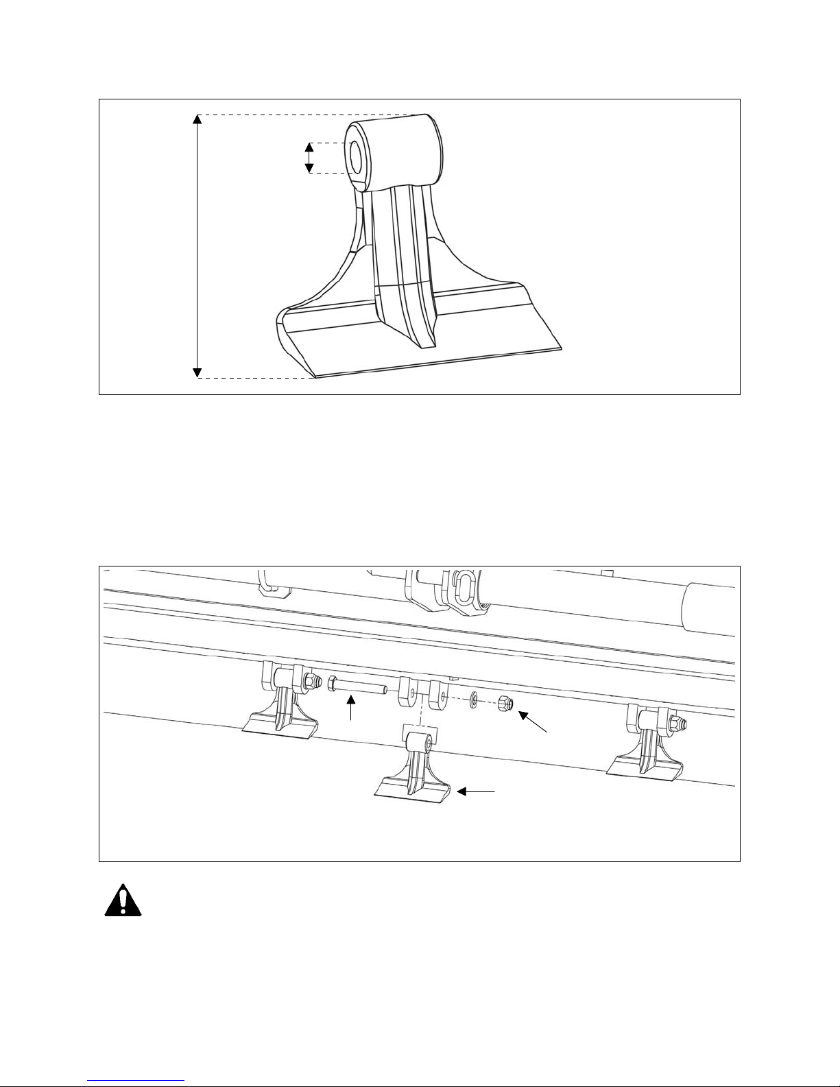
Blades must be kept sharp, at their original length and corners maintained. A blade
must be replaced if, due to wear or damage, its original shape has been distorted.
Blades should be replaced when their total length is less than 5” or when the hole that
the blade bolt is assembled through has ovalized 5/64” over its original diameter (see.
fig. 7).
11
12
See Table 1, page 30.
See Section 4.04 - Belt Tension.
MAINTENANCE 23 BEFCO
Page 24
ESTROYER D90 OPERATOR’S MANUAL
D
Fig. 7
5/64" maximum
hole ovalization
5" minimum
blade length
Installing or removing blades
If the shredder blades need to be replaced, do the following (see. fig. 8):
1. Loosen and remove the lock nuts.
2. Remove the worn blades from the blade carrier welded onto the rotor. Replace with
new blades.
3. Ensure the cutting edge of the blades is the leading edge in the direction of rotation.
4. Replace the bolt and tighten using a new nut then torque to 250 N.m. (185 lb.ft).
Fig. 8
1. blade bolt
2. lock nut
3. blade
DANGER: Proper torque must be used when tightening the blade retaining bolt.
Always use new nuts when replacing blades. If these safety precautions are not
followed, the blade could come off during operation and be thrown 100 yards or
MAINTENANCE 24 BEFCO
1
2
3
Page 25

ESTROYER D90 OPERATOR’S MANUAL
D
more from the shredder. Ensure that once the bolts are tight, the blades are able
to pivot freely. This is imperative to not cause damage to the shredder.
DANGER: Always remember the rotor must remain well balanced at all times to
avoid dangerous vibrations which can damage the overall structure of the
shredder and cause serious injury to any nearby persons. It is therefore
recommended that whenever worn blades are changed, the entire set be changed
to avoid unbalancing the rotor with blades of different weights. If a single blade
or set in a certain area is replaced, it is best to also replace the blade or set of
blades opposite to maintain balance.
If after replacing some of the blades, the vibration remains or increases, it is best
to then replace the entire set.
If this still does not remove the vibrations, the shredder should be taken to an
Authorized Company Dealership to determine if it is necessary to rebalance the
rotor.
CAUTION: When the blades are replaced, it is important that all the blades are of
the same type and weight. A rotor unbalanced by different blades can damage the
shredder.
CAUTION: Do not substitute blades or any bolt for the blade retaining bolt.
Company blades and blade retaining bolts are specially made for this application.
Using non original parts can effect the quality of cut and may also cause damage
to the shredder.
4.04 - Belt Tension
Belt tension control
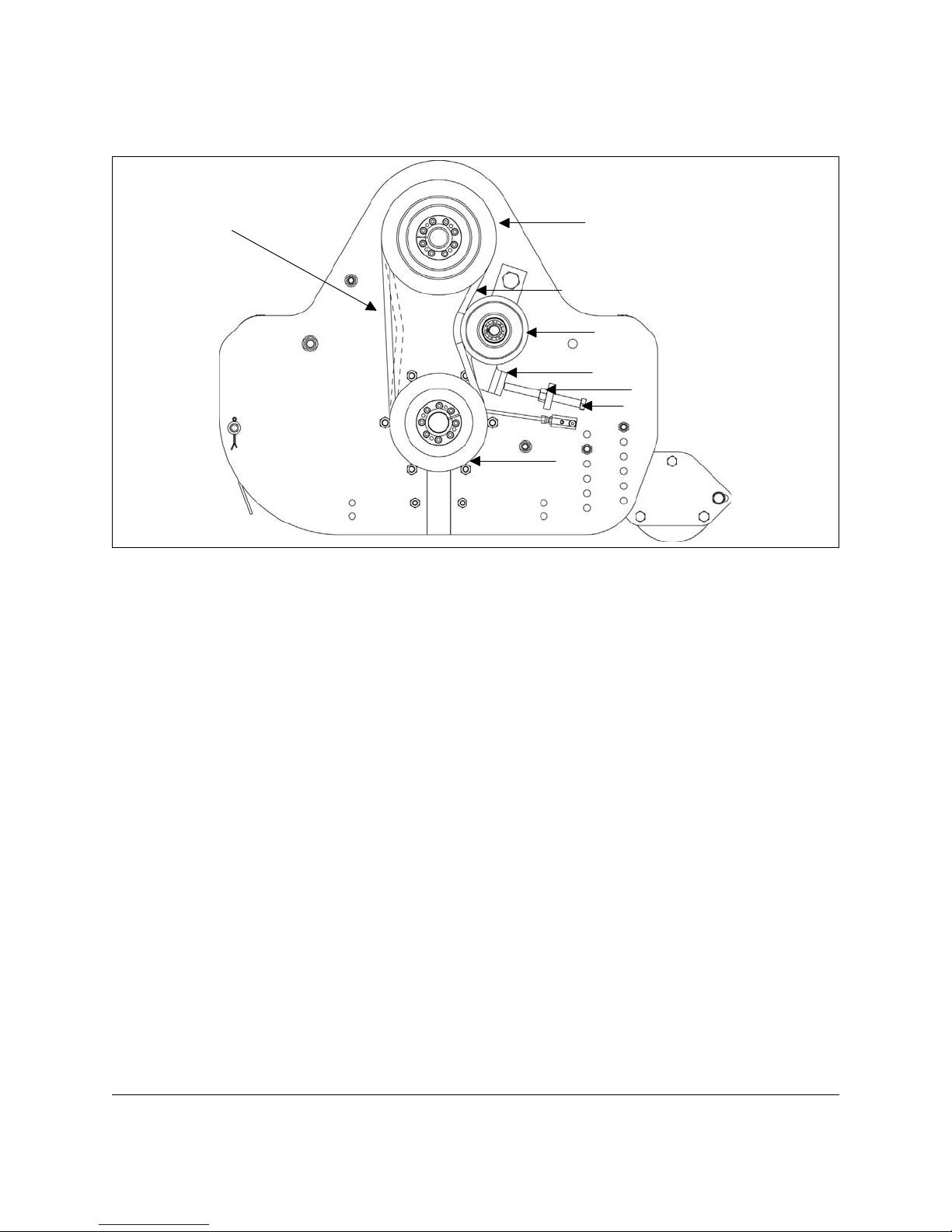
Check the tension of the four belts (see fig. 9) by applying a force of 12-15 lb. pushing
against each belt halfway between the pulleys. The belt deflection should be between
5
/16”-3/8”.
Belt tension adjustment
The Destroyer D90 flail shredder is equipped with a lateral belt transmission with a
manually loaded belt tensioner. The tension is applied by a tensionner pulley and is
regulated with an adjustment bolt (see #6, fig. 9) which protrudes from the belt shield.
To adjust the tension do the following (see fig. 9):
1. Loosen the locking nut.
2. Screw the adjustment nut until the correct belt tension is reached.
MAINTENANCE 25 BEFCO
Page 26
ESTROYER D90 OPERATOR’S MANUAL
D
3. Tighten the locking nut.
Fig. 9
belt deflection
5/16"-3/8"
1
1. upper pulley
2. belts
2
3. belt tensioner
4. pulley support
3
4
bracket
5. locking nut
5
6. adjustment bolt
6
7. lower pulley
7
4.05 - Belt Replacement
If the belts have been stretched or damaged to the point where the proper tension can
not be obtained they must be changed. All four belts must be changed at the same time.
To replace the belts do the following:
1. With the shredder stopped supported by stands, remove the belt shield. Clean the
belts, pulleys and shield of grass, dust and dirt.
2. Loosen the locking nut and unscrew the adjustment bolt (see fig. 9).
3. Remove the old belts one at a time and replace them with the new belts using a
screwdriver if needed.
4. Tighten the belts with the adjustment bolt then secure it with the locking nut.
5. Ensure that the belts are at the proper tension (see fig. 9).
6. Replace the belt shield.
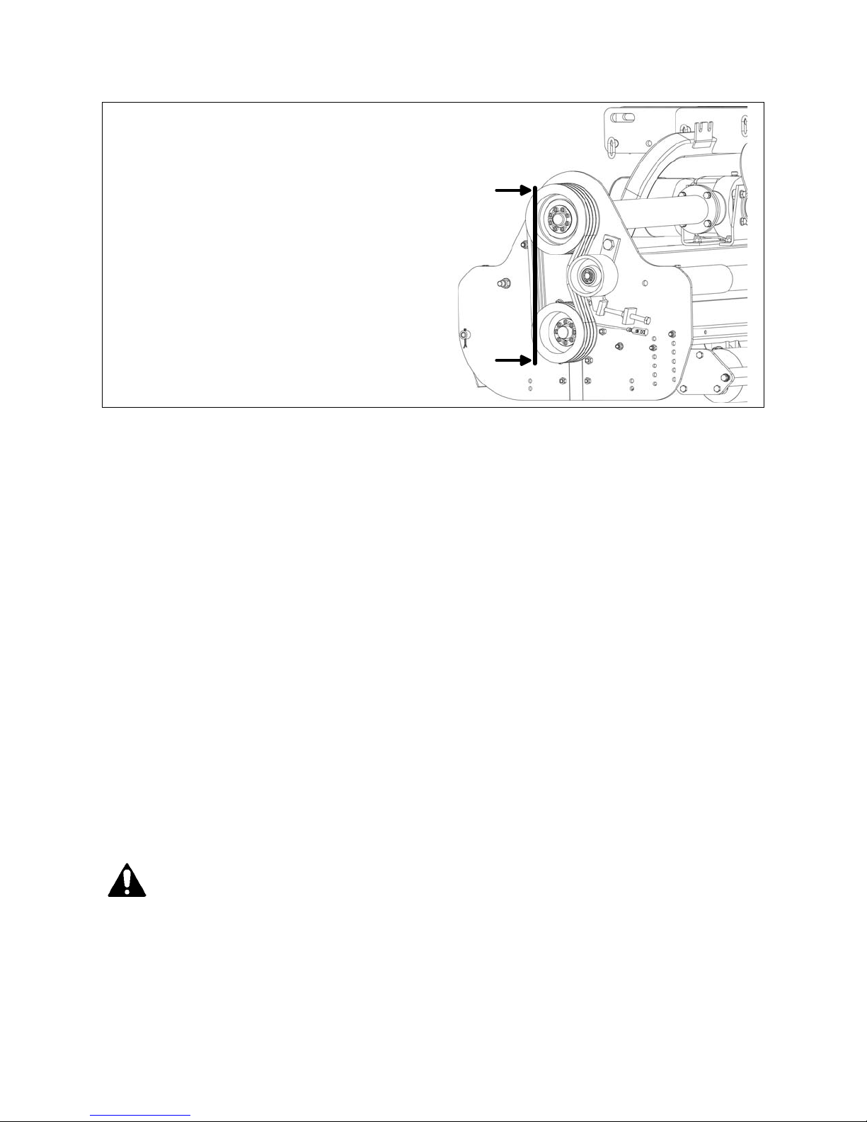
For proper operation and extended belt life the upper and lower pulley of the shredder
need to always work aligned to one another. After replacing the belts, place a straight
edge over two sides of each pulley to check their alignment (see fig. 10). If the pulleys
are aligned the straight edge should lay evenly across the surface of both pulleys
13
MAINTENANCE 26 BEFCO
See Section 5.02 - Pulleys, for instructions on removing and replacing pulleys.
4.06 - Pulley Alignment
13
.
Page 27
ESTROYER D90 OPERATOR’S MANUAL
D
Fig. 10
Apply a straight edge over the sides of
the pulleys to check their alignement.
4.07 - Reverse Gearbox Direction
The D90 flail shredder in its standard configuration is to be used with a tractor that has a
shaft that turns clockwise.
It is possible to reverse the direction of rotation of the output shaft on the gearbox and
therefore to use the flail shredder with a tractor that has a shaft with a counter clockwise
rotation.
To reverse the direction it is necessary to move the ring gear to the other side of the
PTO shaft and to replace the overrunning clutch with a left-turning clutch. This operation
entails opening the drive transmission. We recommend this be done only at an
Authorized Company Dealership.
Note: The flail shredder comes with a PTO driveline equipped with a right-turning
overrunning clutch (clockwise). Always check the direction of rotation on the tractor’s
PTO to be sure it is the same as the overrunning clutch. If the tractor comes with a
left-turning PTO (counter clockwise) the overrunning clutch must be changed to
left-turning as well.
4.08 - Driveline
DANGER: Only use the original driveline supplied with this shredder and always
with the safety shielding.
Carefully read and file away the driveline operator’s manual supplied by the
manufacturer. The following does not substitute the information found in the
driveline manual.
MAINTENANCE 27 BEFCO
Page 28
ESTROYER D90 OPERATOR’S MANUAL
D
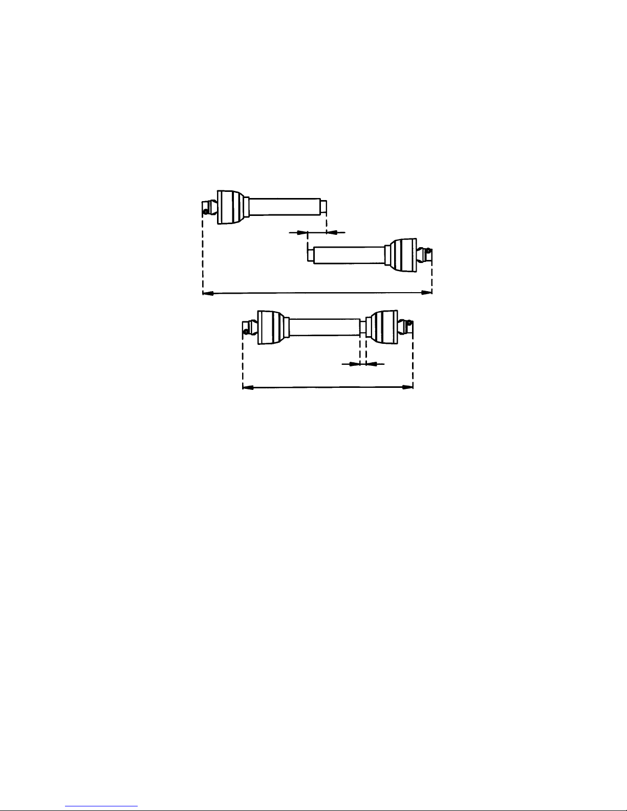
IMPORTANT: Always check driveline length during initial setup and when connecting to
a different tractor.
In the collapsed position the driveline should be approximately 2” from bottoming out to
prevent possible damage to the tractor or implement. When the driveline is in the
maximum extended position, the ideal minimum overlap of the two halves should be
approximately 6” (see fig. 11).
Fig. 11
min. 6"
MAX.
min. 2"
MIN.
If determined that the driveline is too long, follow these procedures to adjust the length:
1. Separate the two driveline halves. Connect one half to the tractor PTO and the other
half to the shredder.
2. Raise and lower the shredder with the 3 point hitch to find the position where the
driveline is shortest. Hold the half shafts side by side and mark the desired length on
1
the outer female tube guard leaving a 1
/2” gap between the end of the guard tube
and bell guard.
3. Cut off both guard tubes the same amount as marked in step 2.
4. Shorten both drive tubes the same amount as guard tubes.
5. De-burr and clean filings from drive tubes and apply grease to outside of inner
telescoping tube.
6. Reassemble the driveline halves and connect to tractor and shredder. Raise and
lower shredder again to be sure driveline does not bottom out in its shortest position
and has a minimum overlap of 6” in the longest position.
7. Install both driveline safety chains. One should be hooked in a hole on the outer
driveline yoke shield and to the tractor to restrict outer shield rotation. The second
one should be hooked in a hole on the inner driveline yoke shield and to the
implement to restrict inner shield rotation.
If determined that the driveline is too short for your tractor, contact your Authorized
Company Dealer.
MAINTENANCE 28 BEFCO
Page 29

ESTROYER D90 OPERATOR’S MANUAL
D
CAUTION: Always work with the driveline as straight as possible. This will
prolong its life and that of its components. It is advised not to work at an angle
greater than 15 degrees.
4.09 - Overrunning Clutch
The shredder is supplied with a PTO driveline that comes equipped with an overrunning
clutch. The PTO yoke end is attached to the tractor’s PTO, while the end with the
overrunning clutch is attached to the shredder. The purpose of the overrunning clutch is
to transmit power in one direction only.
The overrunning clutch is indispensable for use on very fast operating machines,
because when the rotation is suddenly halted, the inertia reverses the direction of
rotation which could cause implement or tractor damage and put the operator or
bystander in danger.
MAINTENANCE 29 BEFCO
Page 30
ESTROYER D90 OPERATOR’S MANUAL
D
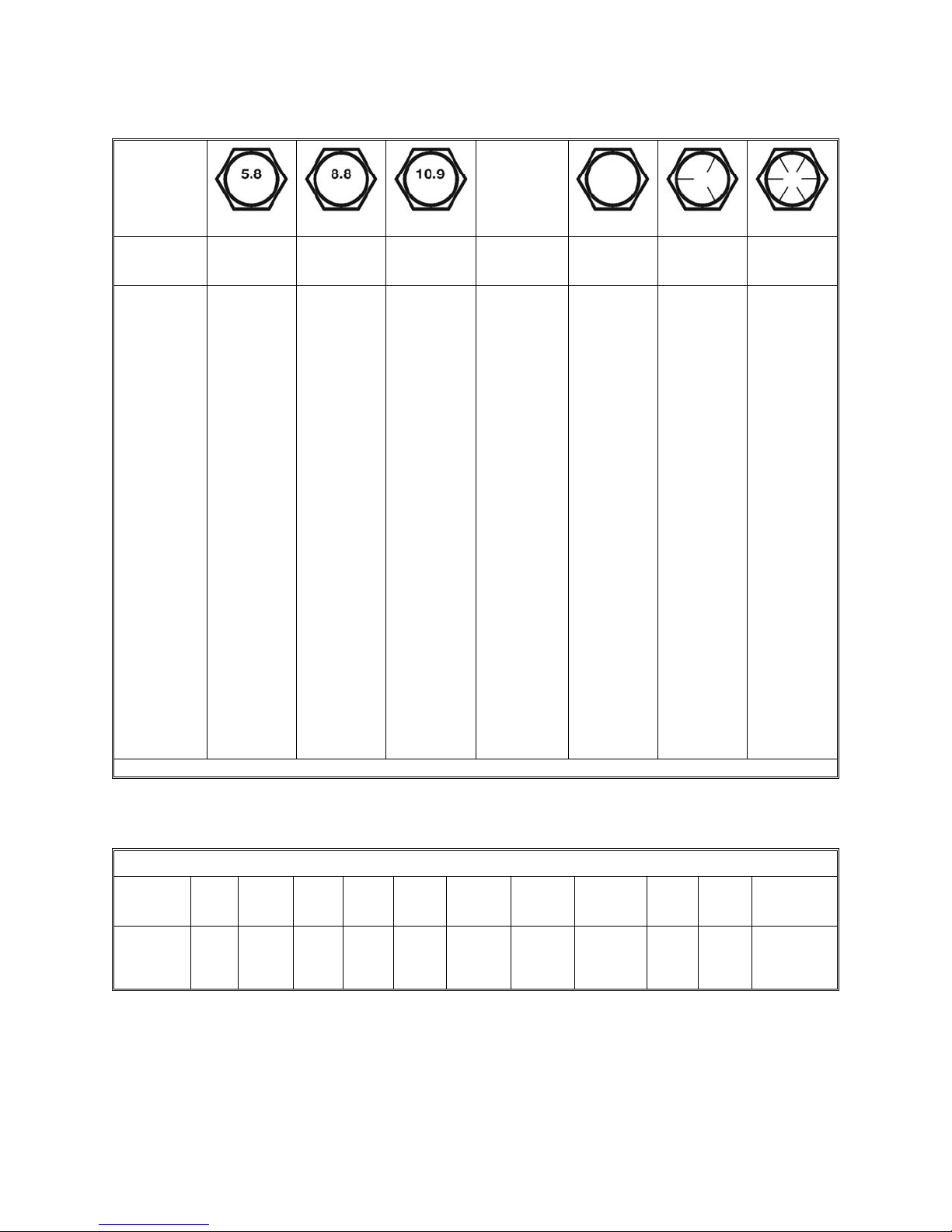
TABLE 1 - TORQUE SPECIFICATIONS
Metric (ISO)
treaded
bolts head
marking
Bolt
Thread
size
mm
When using lock washers with nuts, increase torque values by 5%.
mm
0.8M5
1M6
1.25M8
1M8
1.5M10
1.25M10
1M10
1.75M12
1.5M12
1.25M12
2M14
1.5M14
2M16
1.5M16
2.5M18
2M18
1.5M18
2.5M20
1.5M20
2.5M22
1.5M22
3M24
2M24
3M27
2M27
3.5M30
2M30
4M36
Class 8.8Class 5.8
Class 10.9
ft-lbN.mft-lbN.mft-lbN.m
794634
111571046
273618251216
283819261317
527135482331
557538512433
587839532635
9112362844054
9412864874156
9813366904459
144195981336284
1542091051426994
22330215220697131
236320161218104141
310421218295133181
327443229311145196
343465241327150203
437592306415189256
476646335454212288
595807418567254344
644873452613281381
7501017526714327444
8081095567769360488
110314967741050484656
117615948251119530719
1499203310471420668906
16592250118016007381000
260735351830248211311534
Inch (SAE)
treaded
bolts head
marking
Thread
Bolt
inch
size
inch
tpi
201/4”
281/4”
185/16”
245/16”
163/8”
243/8”
147/16”
207/16”
131/2”
201/2”
129/16”
189/16”
115/8”
185/8”
103/4”
163/4”
97/8”
147/8”
81”
121”
71-1/8”
121-1/8”
71-1/4”
121-1/4”
61-3/8”
121-3/8”
61-1/2”
121-1/2”
Grade 8Grade 5Grade 2
ft-lbN.mft-lbN.mft-lbN.m
121681157
1419101368
253317241115
273719261317
445931422027
496735472331
709549673243
7810655753648
106144751024866
120163851155575
1542081091477095
17123212116479106
21228715020397132
240325170230110149
376509266361172233
420569297403192261
606822430582167226
668906473642184249
9091232644873250339
9951348704955273371
128817467941077354480
144519588911208397539
1817246311201519500677
2012272812411682553750
2382323014691992655888
27123677167322687461011
31614286194926438691179
35574823219429749781326
TABLE 2 - DESTROYER D90 FLAIL SHREDDER - TECHNICAL FEATURES
Series D90, for tractors up to 90 HP, PTO 540 rpm, 3 point hitch cat. 1 & 2
Working
HPModel
width
MAINTENANCE 30 BEFCO
Overall
width
Weight
lb.
Rotor
rpm/min
Blades tip
speed
ft/min
side-shift
# HammersHydraulic
Cutting
height
# Belts
& Type
Driveline
w/overrunning
ASAE 6
ASAE 6
ASAE 6
clutch 1
3
/8”
th.
cat4 XPBX¾”-5”1612”8,3881,9611,25769”60”40-90D90-060
th.
cat4 XPBX¾”-5”2016”8,3881,9611,34581”72”50-90D90-072
th.
cat4 XPBX¾”-5”2416”8,3881,9611,49196”88”60-90D90-088
Page 31

ESTROYER D90 OPERATOR’S MANUAL
D
5 - REPAIR PROCEDURES
CAUTION: All repair procedures must be done by authorized dealerships. It is not
recommended that untrained individuals perform any repair work. The following
operations are detailed for qualified personnel only.
5.01 - Gearbox
To remove the gearbox from the frame do the following:
1. Remove the belt cover.
2. Disengage the belt tensioner pulley by releasing the adjustment bolt (see #6, fig.
9)14.
3. Remove the belts
4. Unbolt the bolts holding the gearbox to the frame.
5. Unbolt the nuts which hold the gearbox to the drive tube.
15
.
If it is necessary to replace any part on the inside of the gearbox, it is important to
replace oil seals or gaskets to ensure a tight fit when reassembling.
To replace the gearbox, follow the above instructions in reverse order.
5.02 - Pulleys
To remove the pulleys do the following:
1. Remove the belt cover.
2. Disengage the belt tensioner pulley by releasing the adjustment bolt (see #6, fig.
9)16.
3. Remove the top and bottom split lock bushings by removing all the screws that hold
them and transferring the required number of screws into the push-off threads.
Tighten the screws in a crosswise pattern in several steps until bushings disengage.
4. Remove pulleys.
To replace the pulleys do the following:
1. Slide the top pulley on the drive shaft ensuring it is flush with the spacer.
2. Slide the bottom pulley on the rotor shaft ensuring it is flush to the snap ring.
3. Insert the top and bottom split lock bushing, place the screws in the locking bores
and hand tighten the screws. Using a torque wrench set at 30 lb.ft (40 N.m), tighten
the screws in a crosswise pattern in several steps.
4. Place a straight edge across both pulleys to verify their alignment (see fig. 10).
14
15
16
See Section 4.04 - Belt Tension.
See Section 4.05 - Belt Replacement.
See Section 4.04 - Belt Tension.
REPAIR PROCEDURES 31 BEFCO
Page 32

ESTROYER D90 OPERATOR’S MANUAL
D
5. Install the belt cover.
Note: For proper pulley alignment it is important to ensure that the top pulley is
assembled flush on the spacer and the bottom pulley is assembled flush on the snap
ring.
5.03 - Rotor Shaft
To remove the rotor do the following:
1. Remove the belt cover.
2. Disengage the belt tensioner pulley by releasing the adjustment bolt (see #6, fig.
9)17.
3. Remove the belts18.
4. Remove bottom pulley from the left side of the rotor19.
5. Remove the bolts that hold the locking plate situated under the pulley then remove
the locking plate.
6. Remove the grease fitting on the left side of the rotor and the grease fitting tube.
7. Remove the grease fitting on the right side of the rotor.
8. Remove the bolts that attach the right and left rotor supports to the frame.
9. Slide the rotor from the side panels.
10.Remove the snap ring that holds the right rotor support bearing to the rotor.
11.Remove the snap ring that holds the pulley to the left side of the rotor.
12.Remove the left and right rotor supports from the rotor.
To replace the rotor, follow the above instructions in reverse order.
5.04 - Suggested Spare Parts
It is suggested that the following spare parts be kept on hand for the shredder at all
times to prevent a minor problem from delaying work.
QuantityDescription
1 setBlades
1 setBlade bolts and nuts
4Belts
5.05 - Storage
After seasonal use it is important to perform the following for prolonged storage:
1. Wash the shredder carefully.
2. Inspect the shredder and replace worn or damaged parts.
3. Tighten all hardware.
17
18
19
See Section 4.04 - Belt Tension.
See Section 4.05 - Belt Replacement.
See Section 5.02 - Pulleys.
REPAIR PROCEDURES 32 BEFCO
Page 33
ESTROYER D90 OPERATOR’S MANUAL
D
4. Grease all areas indicated under Maintenance20.
5. Loosen the belts if the shredder is to be stored for an extended length of time.
6. Touch up scratches by sanding the area and applying a light coat of primer and paint
to prevent rust from forming.
7. Cover the shredder from the elements in order to have it in perfect condition for the
start of the next season.
8. Make sure all parked machines are on a hard, level surface, and engage all safety
devices.
9. Do not permit children to play on or around the stored unit.
Touch up paint available:
Part #
Description
Primer, gray - aerosol spray can7300007
Paint, Befco orange - aerosol spray can7300008
Paint, Befco black - aerosol spray can7300010
WARNING: Be sure to store the implement on a hard level surface and away from
people especially children.
Note: The machine demolition operations should be carried out in compliance with all
federal, state and local environment protection laws.
20
REPAIR PROCEDURES 33 BEFCO
See Chapter 4 - Maintenance.
Page 34

ESTROYER D90 OPERATOR’S MANUAL
D
6 - TROUBLESHOOTING
WARNING: Be sure tractor engine is off, parking brake is locked, and key is
removed before making any adjustments.
SOLUTIONPOSSIBLE CAUSEPROBLEM
Uneven
cutting.
Grass not cut
and/or bent
over.
Belts squeal.
blade wear.
Shredder
vibrates.
Noisy
shredder.
Striping or
windrowing.
out of
gearbox
breather cap.
Machine not parallel to the ground.
Blades are worn or bent.
Loose belts.
Wrappings around rotor.
Wet grass.
Grass too high.
Tractor rpm too slow.
Belts slipping due to loose belts.
Belts slipping due to high grass.
Worn, broken or bent blades.
Shredder not running at proper
PTO speed.
Object wrapped around rotor.
Rotor out of balance.
Loose components.
Excessive rpm.
Low oil in gearbox.
Worn, broken or bent blades.
Grass not being picked up after
tractor tires tracks.
Shredder not running at rated PTO
rpm.
Shredder not level.
Wrapping or material buildup.
Gearbox overfilled.Oil blowing
Roller is not in the same adjustment hole
pattern.
The tractor lift arms are not lifting equally.
Change blades.
Adjust belt tension.
Remove wrappings.
Allow grass to dry.
Raise shredder, shift to lower gear, make
two passes over grass. Mow grass high 1
pass, 2
nd.
pass cut to desired height.
Increase tractor rpm, check engine and
PTO speeds.
Tighten belts.
Raise shredder, shift to lower gear, make
two passes over grass. Mow grass high 1
pass, 2
nd.
pass cut to desired height.
Raise the cutting height.The cutting height is too low.Excessive
Replace blades.
Set tractor throttle for 540 rpm.
Remove object.
Balance rotor.
Tighten hardware.
Back off tractor rpm to 540.
Fill to proper level.
Replace blades.
Grass is too high. Cut in two passes at a
slower ground speed.
Set tractor throttle for 540 rpm.
Level shredder with tractor hitch arms.
Clean rotor.
Use a siphon pump to drain excess oil out
of gearbox.
st.
st.
TROUBLESHOOTING 34 BEFCO
Page 35

ESTROYER D90 OPERATOR’S MANUAL
D
7 - PRE-DELIVERY CHECKLIST
To the dealer: Inspect the machine thoroughly after assembly to assure it is
functioning properly before delivering it to the customer. The following checklist
is a reminder of points to cover. Check off each item as it is found satisfactory or
after proper adjustment is made.
Gearbox oil level.
Guards and shield properly fastened.
Lubrication of grease fittings.
All hardware properly tightened.
All decals properly located and readable (see fig. 2).
Blades properly installed, blade bolts and nuts tightened.
Overall condition (touch up scratches, clean and polish).
Test run, check for excessive vibration or overheating of bearings.
Operator’s Manual.
Review the Operator’s Manual with the customer. Explain the following:
Warranty.
Safe operation and service.
Correct machine installation and operation.
Daily and periodic lubrication, maintenance and inspections.
Troubleshooting.
Operational procedures and storage.
Parts and service.
Fill out the Pre-Delivery Checklist and Warranty Registration form.
Give customer the Operator’s Manual and encourage the customer to read the
manual carefully.
IMPORTANT: Warranty is not valid unless Pre-Delivery Checklist and Warranty
Registration form in Operator’s Manual is completed in detail and mailed to the
Company.
Model Number: __________ Serial Number: __________
Delivery Date: __________ Dealer’s Signature: __________
PRE-DELIVERY CHECKLIST 35 BEFCO
Page 36

ESTROYER D90 OPERATOR’S MANUAL
D
8 - WARRANTY
BEFCO’s responsibility will be limited to substitution of the acknowledged defective
merchandise to the same place of delivery as the previous one was supplied.
1. LIMITED WARRANTY
BEFCO, Inc. herein referred to as the Company, warrants its machines and related
accessories, hereafter referred to as the Machine, to be free from defects in material
and workmanship, for a period of twelve (12) months from the date of invoice to the first
registered owner; this limited warranty does not apply to common wear items and
excludes belts, shear pins, oil, grease, tires, tubes, hydraulic hoses, knives and PTO
shafts.
Labor will be reimbursed at $40.00 per hour based on BEFCO’s time schedule.
Cost of transport to the servicing dealer is the responsibility of the customer.
Warranty coverage shall not be transferable from the first owner to any subsequent
owner.
2. DISCLAIMER OF ALL OTHER WARRANTIES AND REMEDIES
Neither the Company nor any company affiliated with the Company makes any
warranties, representations or promises, expressed or implied, as to the quality,
performance or application of its products other than those set forth herein and
does not make any implied warranty of merchantability or fitness.
The only remedies the purchaser has in connection with the breach, or
performance of any warranty on the Company’s Machine are those set forth
herein. In no event will the dealer, the Company, or any company affiliated with
the Company, be liable for:
a. Injuries or damages of any kind or nature, direct, consequential or
contingent to person or property.
b. Any expenses incurred by the owner to repair, replace or rework any
allegedly defective item.
c. Any loss, cost, forfeiture or damages (including loss of profits; loss of
crops; loss because of delay in field operations; any expenses or loss
incurred for labor, supplies, substitute machine rental; liabilities of the
owner to its customers or third persons; and all other consequential
damages, losses, liabilities or damages for any other reasons) whether
direct or indirect, and whether or not resulting from or contributed to by the
default or negligence of the Company, its agents, employees and
subcontractors which might be claimed as a result of the use or failure of
the equipment delivered.
The Company’s liability based on this limited warranty or any other applicable
laws shall be limited to replacement or refund of the purchase price of the
product.
The limited warranty extended herein gives you specific rights and you may also
have other rights which vary from state to state. Neither the dealer nor the
Company personnel has the authority to make any representation or to modify
the terms and limitations of this warranty in any way.
WARRANTY 36 BEFCO
Page 37

ESTROYER D90 OPERATOR’S MANUAL
D
Other than the limited warranty extended hereby there is no other expressed
warranty in connection with the design, safety or use of any of the Company’s
products except as to title. All implied warranties are expressly disclaimed
pursuant to the terms of this warranty.
3. CUSTOM WORK
If the Machine is used for commercial purposes such as custom work, the period
warranted for the Machine is limited to six (6) months from the date of delivery to the
first registered owner and does not cover any labor charges incurred.
4. RENTAL
If the Machine is used for rental purposes the period warranted for the Machine is
limited to thirty (30) days from the date of delivery to the first registered owner and does
not cover any labor charges incurred.
5. REGISTRATION
In order to qualify for coverage on this limited warranty, the product and name of the
original purchaser must be registered with the Company by a completed Machine
Pre-Delivery Checklist and Warranty Registration along with a copy of the dealer’s
invoice to the first registered owner to the Company within fourteen (14) days after the
date of delivery to the original purchaser.
6. WARRANTY SERVICE
Warranty Service must be performed by a dealer authorized by BEFCO. If the warranty
service requested is approved, the owner shall pay only for labor beyond the rate
allowed, for overtime labor, and for any mileage charge for transporting the equipment
to and from the dealer’s shop. It is assumed that the dealer has the appropriate general
and special tools to service the Machine. Time required for replacement of knives, oil,
grease and to remove excessive dirt from the Machine is not subject to reimbursement
by the Company. The owner is required to clean the Machine before presenting it to the
dealer for service work. The Machine must be delivered within thirty (30) days after
failure date by the owner to the dealer to be eligible for warranty consideration.
7. UNAPPROVED SERVICE OR MODIFICATION
All obligations of the Company under this limited warranty shall be terminated if:
a. Proper service and operation instructions as outlined in the Operator’s Manual
and on the instruction sticker on the Machine, are not followed.
b. The Machine is modified or altered in any way not approved by the Company.
c. The Company does not receive a copy of the dealers invoice to the first
registered owner within fourteen (14) days from the date of delivery.
d. The Company has not been paid in full, by the dealer, for the Machine.
8. ACCIDENTS AND NORMAL MAINTENANCE
This limited warranty covers defective material and workmanship. It does not cover
depreciation or damage caused by normal wear, accidents, improper maintenance,
improper protection or improper use. The costs of normal maintenance or repairs for
accidents or improper use, and related labor will be borne by the owner.
9. REPLACEMENT PARTS
BEFCO, Inc. warrants replacement parts to be free from defect in material and
workmanship for a period of thirty (30) days from the date of delivery to the original
purchaser.
WARRANTY 37 BEFCO
Page 38

Page 39

WARRANTY REGISTRATION
BEFCO, Inc.
P.O. Box 6036
Rocky Mount, NC 27802-6036 Tel: (252) 977.9920 - Fax: (252) 977.9718
Acct. #
Model # Serial #
Pre-Delivery Checklist:
Oil in gearbox.
Greased fittings.
Safety guards in place.
All hardware tight.
Bolts torqued correctly.
Attached unit to tractor. Yes/No.
Field adjusted. Yes/No.
Test run. Dry/Infield.
Safety decals.
Operator’s Manual.
The machine described above, has been
prepared for delivery according to the
Pre-Delivery Checklist and the Customer has
been instructed in its care and operation and
the condition of warranty.
Retail CustomerDealer
StreetStreet Country
Town State ZipTown State Zip
PhoneDate of delivery Invoice #
Tractor make:
Model: ; HP
Type of operation: Private homeowner,
Landscaping, Commercial maintenance, Golf
Course, Municipality, Turf Farm, others:
Approximate number of acres machine will be
used on annually:
I hereby acknowledge that:
I have received and accepted delivery of the
machine described.
The equipment was checked thoroughly for
loose or missing parts and has been adjusted
in accordance with the Pre-Delivery Checklist.
I have read and understand the nature and
extent of the warranty and understand clearly
that there were and are no other
representations of warranties either expressed
or implied, made by anyone. I have been
advised on proper operation, maintenance and
lubrication procedure of this equipment.
I have been instructed on and do understand
the application, limitation and capacities this
equipment was designed and recommended
for, all as described in the Operator’s Manual
and literature published by the Company.
Inspected by:
This registration along with a copy of the invoice must be sent to BEFCO, Inc.
within 14 days of date of purchase.
Date: Date:
Customer’s Signature: Dealer’s Signature:
Page 40

Fold here
BEFCO, Inc.
Sender:
Place stamp
here
Warranty Department
P.O. Box 6036
Rocky Mount, NC 27802-6036
Cut along this line
Page 41
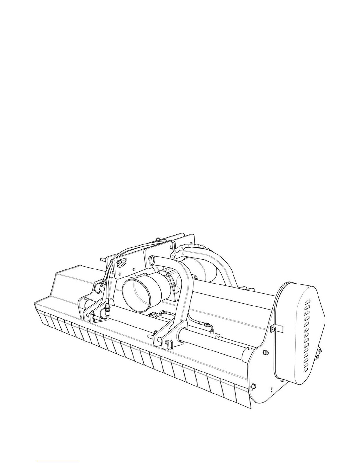
BEFCO®
Parts Manual
DESTROYER
Heavy Duty Flail Shredder
D90-060, D90-072, D90-088
Parts Manual 1116
D90-060, 072, 088
Page 42
DESTROYER D90 THREE POINT HITCH OPERATOR’S MANUAL
D90-060, 072, 088
P
ARTS MANUAL 42 BEFCO
0510
Page 43

DESTROYER D90 THREE POINT HITCH OPERATOR’S MANUAL
D90-060, 072, 088
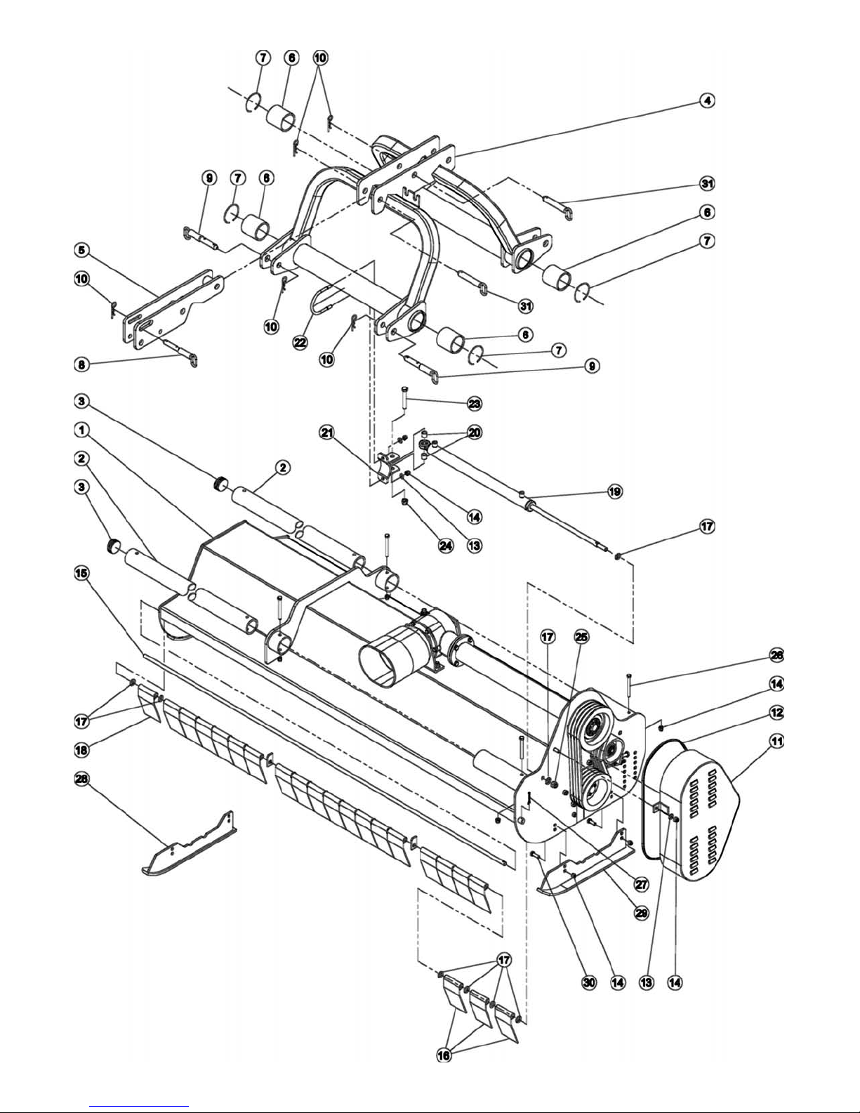
Qty.DescriptionPart #Ref.
1Frame D90-060016-30021
1Frame D90-072026-3002
1Frame D90-088036-3002
2Guide tube D90-060016-30312
2Guide tube D90-072026-3031
2Guide tube D90-088036-3031
2Rubber cap Ø70006-30333
1Double three point hitch006-34224
1Bracket, top hitch006-34315
4Bushing006-30586
4Ring SB 90006-30607
1Pin, top hitch006-30618
2Pin, hitch006-30659
5Hairpin cotter Ø4 Z009-150710
1Belt cover006-325111
1Rubber strip006-325512
4Washer, flat Ø12 Z000-226513
12Nut ES M12-1.75 Z TK001-334514
1Deflector rod D90-060016-334515
1Deflector rod D90-072026-3345
1Deflector rod D90-088036-3345
15Deflector D90-060006-334816
18Deflector D90-072006-3348
22Deflector D90-088006-3348
-Washer, flat Ø16000-856817
1Deflector, narrow; D90-072006-335018
1Hydraulic cylinder D90-060006-336519
1Hydraulic cylinder D90-072, D90-088006-3366
2Spacer006-337420
1Mounting bracket, cylinder006-337521
1U bolt 006-338022
1Bolt HH M16-2.00x100 C8.8 Z P000-656623
1Nut ES M16-2.00 Z TK002-631424
1Nut ES M16-1.50 Z TK002-010525
4Bolt HH M12-1.75x110 C8.8 Z P001-129226
1Pin, split Ø4x50 Z011-208727
1Skid, right (option)016-347228
1Skid, left (option)026-347229
4Bolt HH M12-1.75x35 C8.8 Z F000-725530
2Pin, top hitch006-343531
P
ARTS MANUAL 43 BEFCO
0510
Page 44
DESTROYER D90 ROTOR AND ROLLER OPERATOR’S MANUAL
D90-060, 072, 088
P
ARTS MANUAL 44 BEFCO
1115
Page 45

DESTROYER D90 ROTOR AND ROLLER OPERATOR’S MANUAL
D90-060, 072, 088
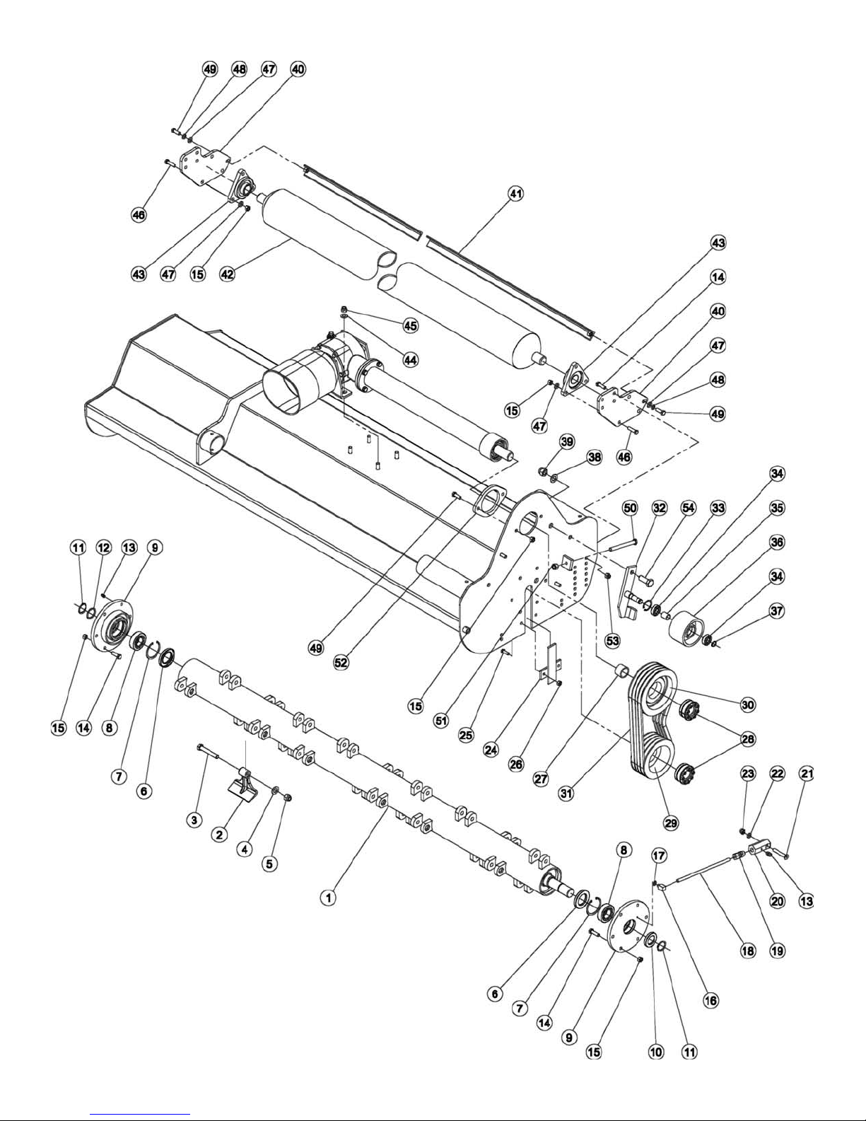
Qty.DescriptionPart #Ref.
1Rotor D90-060016-31021
1Rotor D90-072026-3102
1Rotor D90-088036-3102
16Hammer D90-060006-31142
20Hammer D90-072006-3114
24Hammer D90-088006-3114
16Bolt HH M16-1.50x100 C10.9 Z P; D90-060006-31163
20Bolt HH M16-1.50x100 C10.9 Z P; D90-072006-3116
24Bolt HH M16-1.50x100 C10.9 Z P; D90-088006-3116
16Washer, flat Ø16 D90-060000-85684
20Washer, flat Ø16 D90-072000-8568
Ø16 D90-088000-8568
24Washer, flat
16Nut ES M16-1.50 C8 Z TK; D90-060 006-31175
20Nut ES M16-1.50 C8 Z TK; D90-072006-3117
24Nut ES M16-1.50 C8 Z TK; D90-088006-3117
2Oil seal 52.85.10000-70946
2Snap ring, inner Ø80000-11547
2Bearing 22208 E006-11618
2Rotor support 006-31419
1Oil seal 40.68.10001-019210
2Snap ring, outer Ø40000-813811
1Spacer washer 40x50x2005-324812
2Grease fitting M06-1.00005-112913
16Bolt HH M12-1.75x40 C8.8 Z F002-326514
20Nut PT M12-1.75 C6 Z TK003-006415
1Grease fitting M06-1.00 90°005-315516
1Washer lock Ø06 Z004-653617
1Grease fitting tube005-990818
1Connector Ø6005-361519
1Grease fitting block005-361620
1Bolt CS M06-1.00x40 C8.8 Z F005-952521
1Washer, flat Ø6 Z005-016622
1Nut ES M06-1.00 Z TK005-016523
1Locking plate006-303524
2Bolt HH M10-1.50x30 C8.8 Z F000-127825
2Nut PT M10-1.50 C6 Z TK003-015626
1Spacer006-322027
2Split lock bushing Ø40x80005-363028
1Pulley SPB 180x4006-321329
1Pulley SPB 212x4006-321830
4Belt XPBX 1340006-321531
1Pulley support 006-322232
1Snap ring, inner Ø47005-014433
2Bearing 6204-2RS005-014234
1Spacer006-323235
1Belt tensioner pulley006-322736
1Snap ring, outer Ø20005-014537
1Washer, flat Ø20 Z004-655538
1Nut ES M20-2.50 Z TK009-017839
2Roller arm 006-307240
P
ARTS MANUAL 45 BEFCO
1115
Page 46
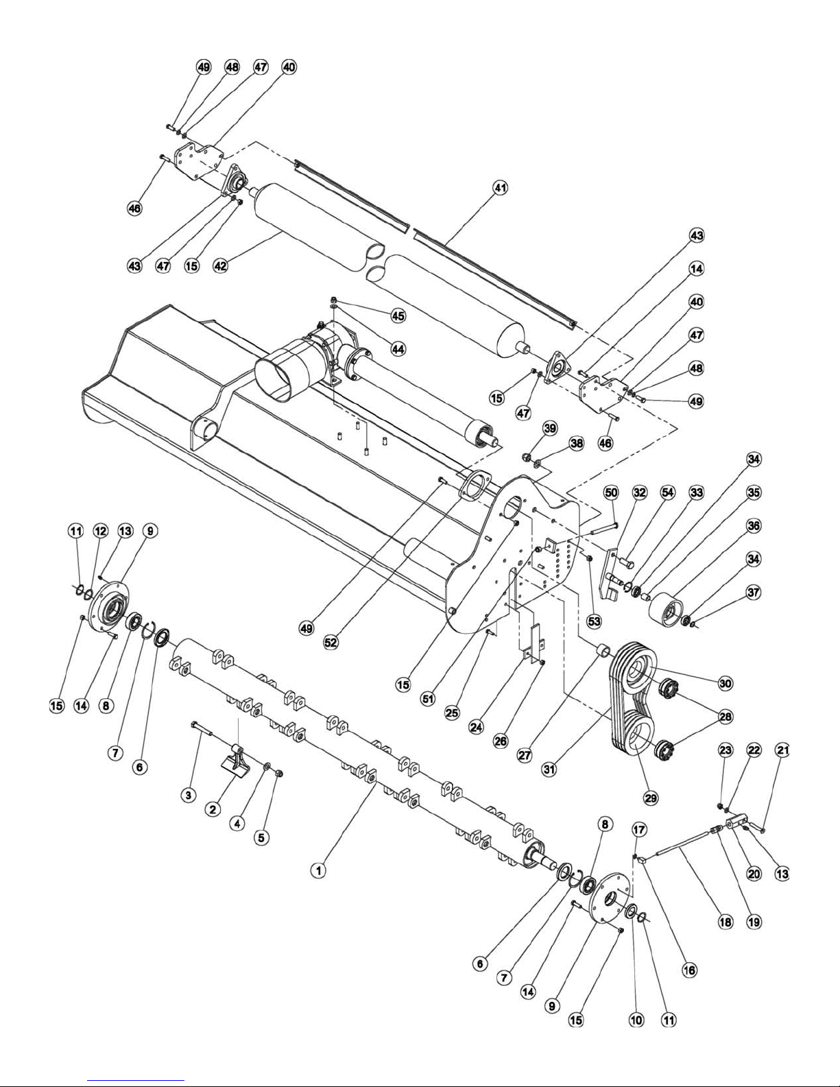
DESTROYER D90 ROTOR AND ROLLER OPERATOR’S MANUAL
D90-060, 072, 088
P
ARTS MANUAL 46 BEFCO
1115
Page 47

DESTROYER D90 ROTOR AND ROLLER OPERATOR’S MANUAL
D90-060, 072, 088
Qty.DescriptionPart #Ref.
1Roller scraper D90-060015-944841
1Roller scraper D90-072025-9448
1Roller scraper D90-088035-9448
1Roller D90-060016-308742
1Roller D90-072026-3087
1Roller D90-088036-3087
2Support USFTE 208005-987343
4Washer, flat Ø14009-143544
4Nut ES M14-2.00 Z TK000-722445
6Bolt HH M14-2.00x45 C8.8 Z P001-674846
8Washer, flat Ø12 Z000-226547
2Washer, lock Ø12 Z000-107748
4Bolt HH M12-1.75x35 C8.8 Z F000-725549
1Bolt HH M14-2.00x150 C8.8 Z F006-323850
1Nut HH M14-2.00 C6 Z TK000-101951
1Support plate, drive shaft tube006-331852
4Nut ES M12-1.75 Z TK001-334553
1Bolt HH M20-2.50x50 C8.8 Z F006-322554
1Washer lock Ø06 Z004-653655
P
ARTS MANUAL 47 BEFCO
1115
Page 48
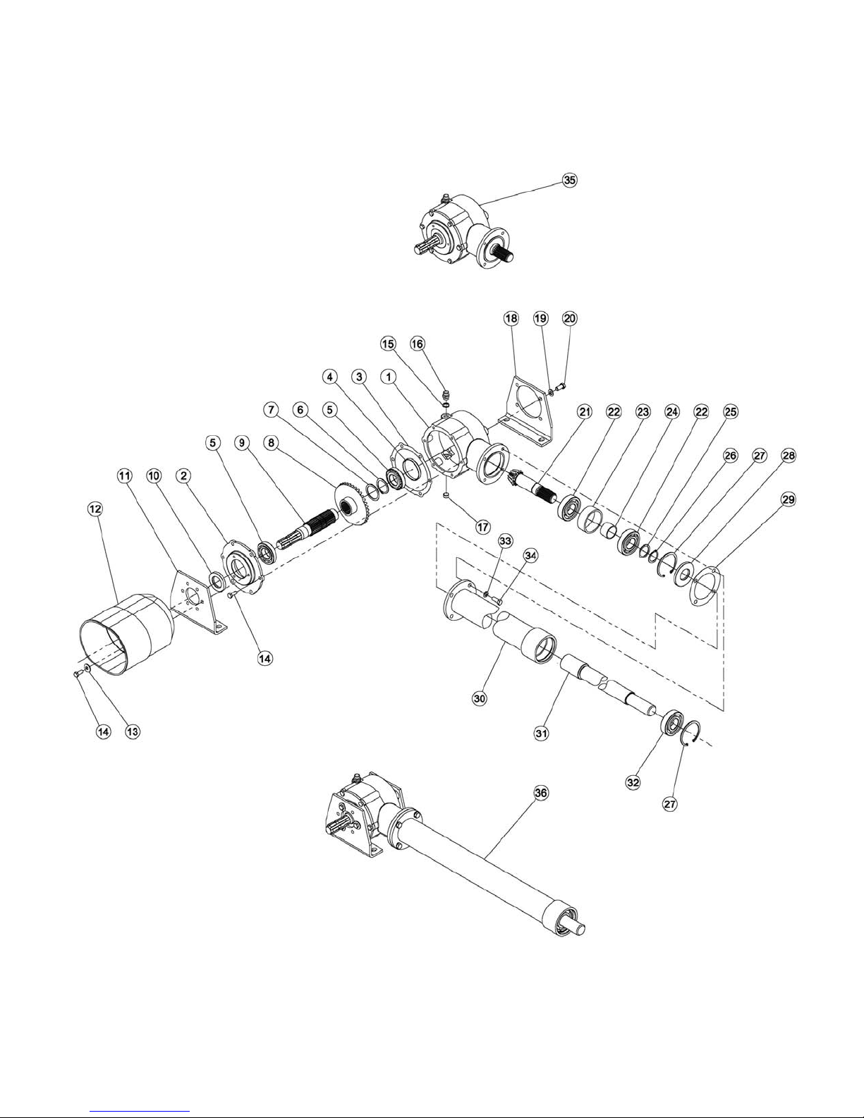
DESTROYER D90 GEARBOX AND DRIVE SHAFT 540 RPM (STANDARD)OPERATOR’S MANUAL
D90-060, 072, 088
P
ARTS MANUAL 48 BEFCO
0516
Page 49

DESTROYER D90 GEARBOX AND DRIVE SHAFT 540 RPM (STANDARD)OPERATOR’S MANUAL
D90-060, 072, 088
Qty.DescriptionPart #Ref.
1Gearbox housing005-34051
1Cover, gearbox housing005-34092
-Gasket 2/10018-02063
-Gasket 5/10028-0206
1Cap005-34214
2Bearing 30208003-0201A5
1Snap ring, outer Ø50002-51156
1Spacer washer 50x62x2005-53247
1Ring gear 006-32828
1Input shaft006-32819
1Oil seal 40.72.10006-327410
1Front plate006-332911
1PTO shaft protection006-335212
3Washer, flat Ø10 Z003-015713
9Bolt HH M10-1.50x25 C8.8 Z F003-317614
1Gasket000-669115
1Breather cap000-1107A16
1Drain plug005-344617
1Rear plate006-333118
4Washer, flat Ø12 Z000-226519
4Bolt HH M12-1.75x25 C8.8 Z F000-303720
1Pinion gear006-328321
2Bearing 6308000-1148A22
1Spacer005-325723
1Spacer005-325324
1Spacer washer 40x50x2005-324825
1Snap ring, outer Ø40000-813826
2Snap ring, inner Ø90 000-813727
1Oil seal 40.90.8005-429028
-Gasket 3/10005-325929
-Gasket 5/10015-3259
1Complete tube drive shaft D90-060016-329930
1Complete tube drive shaft D90-072026-3299
1Complete tube drive shaft D90-088036-3299
1Drive shaft D90-060016-330831
1Drive shaft D90-072026-3308
1Drive shaft D90-088036-3308
1Bearing 6308-2RS000-813632
4Washer, lock Ø12 Z000-107733
4Bolt HH M12-1.75x30 C8.8 Z F001-525534
-Gearbox, complete050-068835
-Gearbox & drive shaft, complete D90-060016-326236
-Gearbox & drive shaft, complete D90-072026-3262
-Gearbox & drive shaft, complete D90-088036-3262
Fill gearbox using approx. 61 fl.oz. (1.9 qt.) of SAE 90W gear oil.Note:
P
ARTS MANUAL 49 BEFCO
0516
Page 50
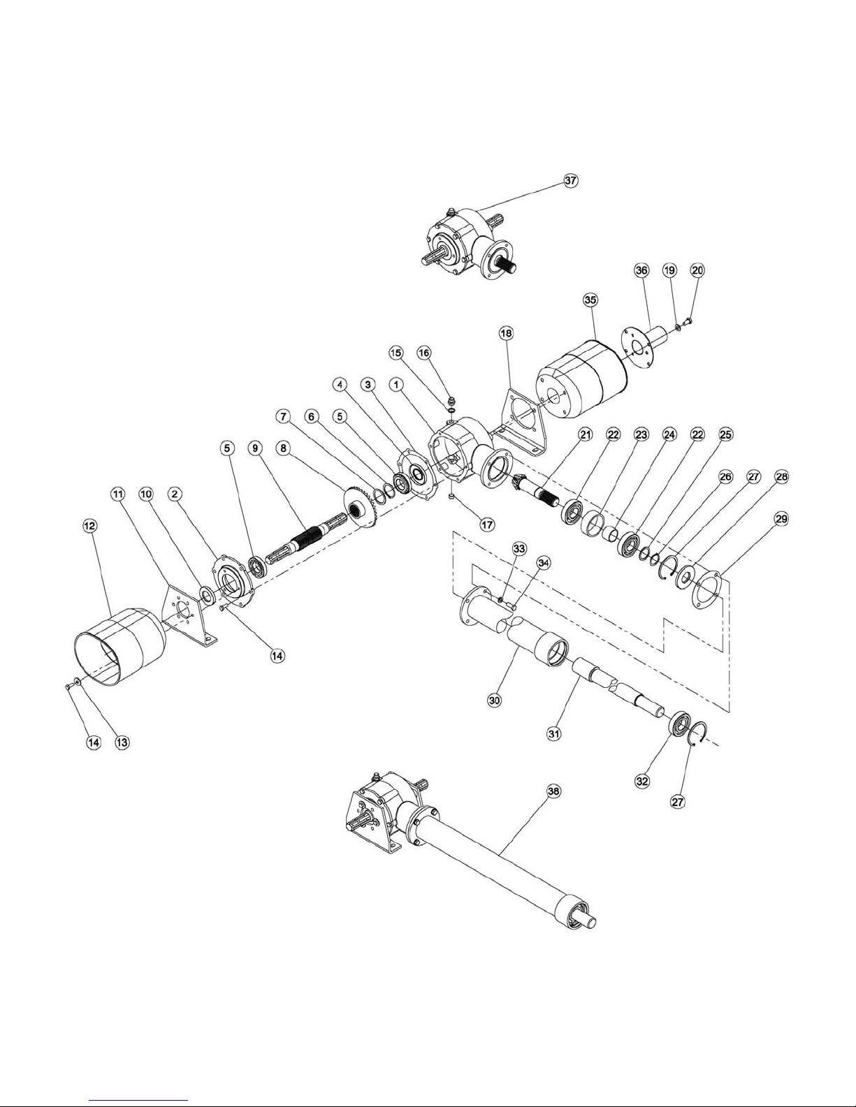
DESTROYER D90 GEARBOX AND DRIVE SHAFT 540 RPM (OPTION W/DOUBLE TRANSMISSION)OPERATOR’S MANUAL
D90-060, 072, 088
P
ARTS MANUAL 50 BEFCO
0516
Page 51

DESTROYER D90 GEARBOX AND DRIVE SHAFT 540 RPM (OPTION W/DOUBLE TRANSMISSION)OPERATOR’S MANUAL
D90-060, 072, 088
Qty.DescriptionPart #Ref.
1Gearbox housing005-34051
1Cover, gearbox housing005-34092
-Gasket 2/10018-02063
-Gasket 5/10028-0206
1Oil seal 40.80.10000-66844
2Bearing 30208003-0201A5
1Snap ring, outer Ø50002-51156
1Spacer washer 50x62x2005-53247
1Ring gear 006-32828
1Input shaft, double006-34569
1Oil seal 40.72.10006-327410
1Front plate006-332911
1PTO shaft protection, front006-335212
3Washer, flat Ø10 Z003-015713
9Bolt HH M10-1.50x25 C8.8 Z F003-317614
1Gasket000-669115
1Breather cap000-1107A16
1Drain plug005-344617
1Rear plate006-333118
4Washer, flat Ø12 Z000-226519
4Bolt HH M12-1.75x25 C8.8 Z F000-303720
1Pinion gear006-328321
2Bearing 6308000-1148A22
1Spacer005-325723
1Spacer005-325324
1Spacer washer 40x50x2005-324825
1Snap ring, outer Ø40000-813826
2Snap ring, inner Ø90 000-813727
1Oil seal 40.90.8005-429028
-Gasket 3/10005-325929
-Gasket 5/10015-3259
1Complete tube drive shaft D90-060016-329930
1Complete tube drive shaft D90-072026-3299
1Complete tube drive shaft D90-088036-3299
1Drive shaft D90-060016-330831
1Drive shaft D90-072026-3308
1Drive shaft D90-088036-3308
1Bearing 6308-2RS000-813632
4Washer, lock Ø12 Z000-107733
4Bolt HH M12-1.75x30 C8.8 Z F001-525534
1PTO shaft protection, rear006-335335
1Protection006-346336
-Gearbox w/double transmission, complete050-068937
-Gearbox & drive shaft, complete w/double transmission D90-060016-345238
-Gearbox & drive shaft, complete w/double transmission D90-072026-3452
-Gearbox & drive shaft, complete w/double transmission D90-088036-3452
Fill gearbox using approx. 61 fl.oz. (1.9 qt.) of SAE 90W gear oil.Note:
P
ARTS MANUAL 51 BEFCO
0516
Page 52
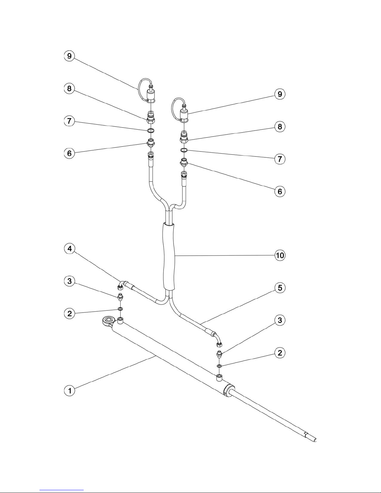
DESTROYER D90 HYDRAULIC CYLINDER OPERATOR’S MANUAL
D90-060, 072, 088
P
ARTS MANUAL 52 BEFCO
05/2010
Page 53

DESTROYER D90 HYDRAULIC CYLINDER OPERATOR’S MANUAL
D90-060, 072, 088
Qty.DescriptionPart #Ref.
1Hydraulic cylinder D90-060006-33651
1Hydraulic cylinder D90-072, D90-088006-3366
2Washer copper 1/4”005-24382
2Nipple 1/4”008-24843
1Hose 2850 mm.; D90-060, 072, 088006-33894
1Hose 2550 mm.; D90-060, 072006-33905
1Hose 2850 mm.; D90-088006-3389
2Nipple 1/4”-1/2”008-24886
2Washer copper 1/2”003-65327
2Quick connector 1/2”004-18718
2Rubber cap006-33969
1Hose sleeve006-339810
P
ARTS MANUAL 53 BEFCO
05/2010
Page 54
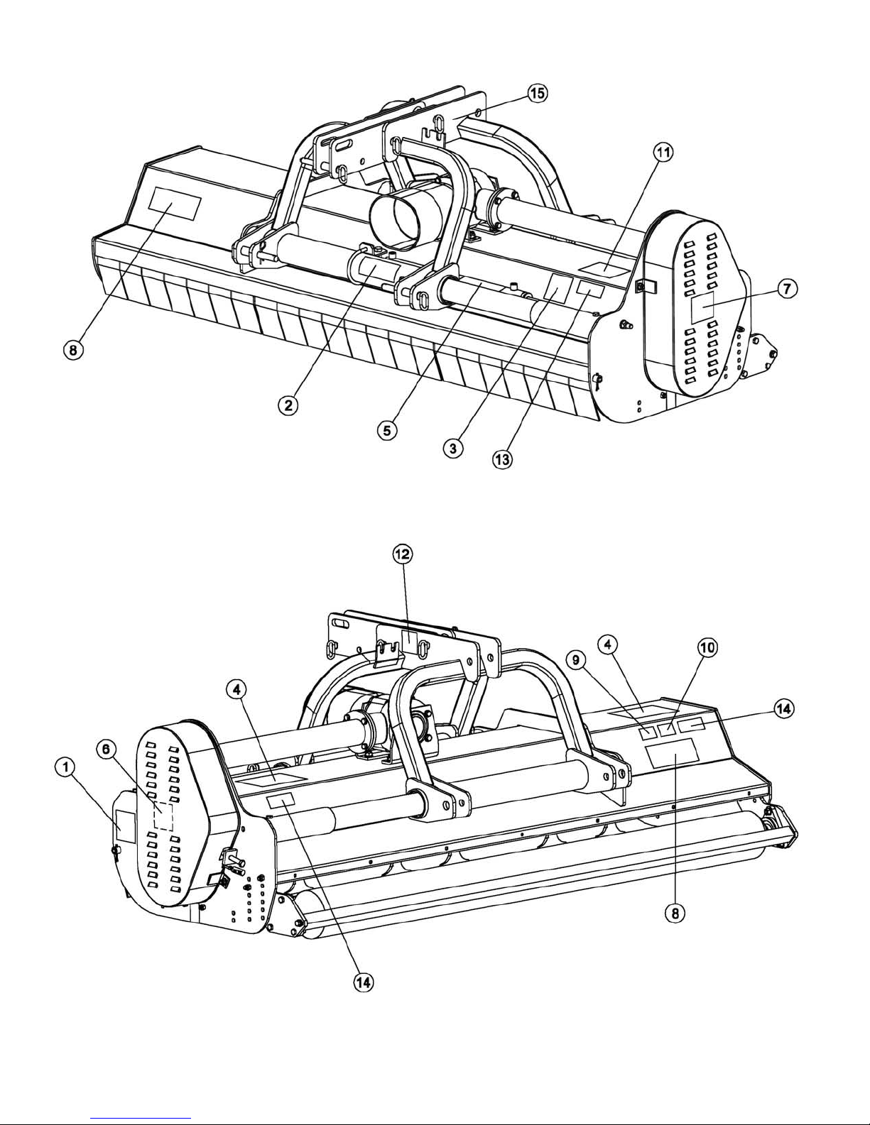
DESTROYER D90 DECALS OPERATOR’S MANUAL
D90-060, 072, 088
P
ARTS MANUAL 54 BEFCO
10/2011
Page 55

DESTROYER D90 DECALS OPERATOR’S MANUAL
D90-060, 072, 088
Qty.DescriptionPart #Ref.
1Decal “DANGER - Moving parts hazard”950-486B1
1Decal “DANGER - Avoid injury from PTO”950-109B2
1Decal “CAUTION - To avoid serious injury”950-111B3
2Decal “DANGER - Rotating blades hazard”950-209B4
1Decal “WARNING - High pressure hydraulic oil leaks”950-408B5
1Decal “DANGER - Replace shields before using” (under shield)950-213B6
1Decal “B”950-103B7
2Decal “BEFCO”950-107B8
1Decal “D90”950-495B9
1Decal “060”950-284B10
1Decal “072”950-285B
1Decal “088”950-282B
1Decal “BEFCO INC.” address950-381B11
1Decal “Quick Hitch Compatible”950-940B12
1Yellow reflective decal; D90-088950-405B13
2Red reflective decal950-366B14
1Decal “Side-shift”937-016015
1Operator’s & Parts Manual “Destroyer D90-060, 072, 088”971-401B
P
ARTS MANUAL 55 BEFCO
10/2011
Page 56
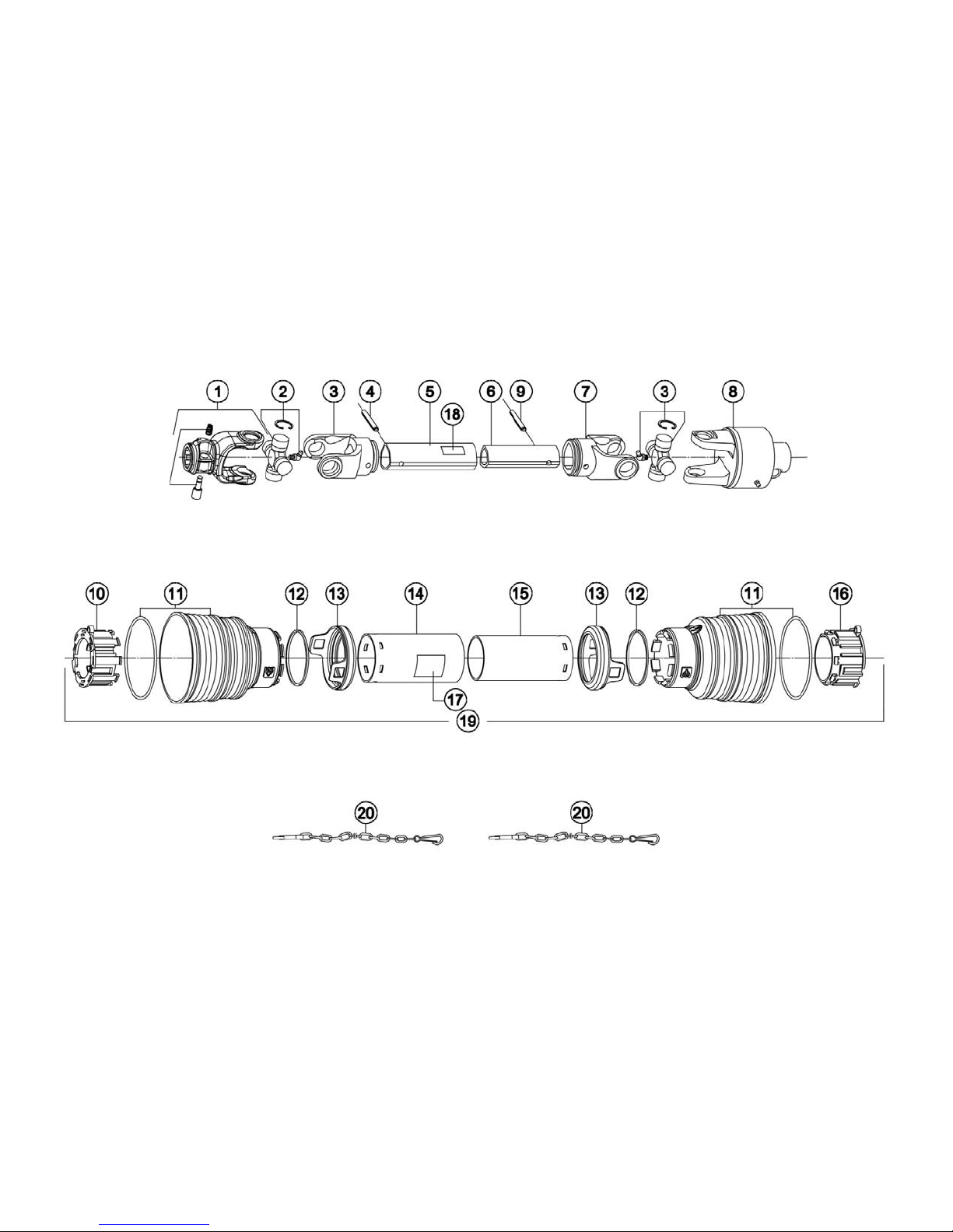
DESTROYER D90 DRIVELINE (OVERRUNNING CLUTCH)OPERATOR’S MANUAL
PARTS MANUAL 56 BEFCO
05/2010
Page 57

DESTROYER D90 DRIVELINE (OVERRUNNING CLUTCH)OPERATOR’S MANUAL
Qty.DescriptionPart #Ref.
1Yoke (tractor end)1026010C1
2Cross & bearing 1006020C2
1Yoke, outer tube 1706027C3
1Roll pin Ø10x80003-22044
1Shaft, outer tube1528041C5
1Shaft, inner tube1526041C6
1Yoke, inner tube1706029C7
1Overrunning clutch (implement end)1746260C8
1Roll pin Ø10x70000-016E9
1Locking ring, outer tube1786710C10
2Standard cone1785703C11
2Stop ring1215735C12
2Safety sleeve1885709C13
1Shield, outer tube1776031C14
1Shield, inner tube1877031C15
1Locking ring, inner tube1786711C16
1Decal “DANGER - Rotating driveline, keep away” outer shield950-463B17
1Decal “DANGER - Guard missing, do not operate” outer tube950-464B18
1Shield, complete90SS6031C19
2Chain, anti-rotation1006065C20
-Driveline w/overrunning clutch, complete050-0471
PARTS MANUAL 57 BEFCO
05/2010
Page 58

Page 59

Use only original spare parts
All rights reserved. It is unlawful to copy, reprint or use any of the information or details in this manual
without the expressed written permission of the Company. Technical information provided in this
manual is approximate, the Company reserves the right to modify or improve the models shown for
technical or commercial purposes. Pictures in this manual do not necessarily show the machine as
delivered.
Page 60

®
P.O. Box 6036
Rocky Mount, NC 27802-6036
Tel.: 252.977.9920 - Fax: 252.977.9718
www.befco.com
BEFCO D90-060, 072, 088 (US).lwp
Printed in the USA, October 7, 2016
®
 Loading...