

Page 1
V C M C
U S E R M A N U A L
Page 2

Page 3
V C M C
U S E R M A N U A L
F U N C T I O N I N D E X
U se r M an u al Re v 1 3 Oct.
Cu rren t Fi rmware v1 . 0
Page 2 PO WER & I N TRO DUCTI ON
Page 3 FI RS T STEPS
Page 4 CO N F. SCREEN & CON TRO LS
Page 5 CV EDIT PT. 1
Page 6 CV E DI T PT. 2
Page 7 FADER ED I T
Page 8 G ATE EDI T
Page 9 CV/FADER ED I T & G LOBAL CO N F I G
Page 1 0 SYS EX & F I RM WAR E
Page 1 1 EX TR AS
.1
Page 4
V C M C
U S E R M A N U A L
P O W E R & I N T R O
P O W E R I N G T H E
M O D U L E
1.
Disconnect your cabinet from the mains.
2.
Triple check the power cord polarity.
(pin number one) is the -12V rail.
3. If you plug the module backwards or in
it out and unfortunately this is not covered by the warranty.
4. If you have any questions about this product please send them to:
support@befaco.org
I N T R O D U C T I O N
VCMC is a Voltage Controlled MIDI Controller, a fully mapable MIDI device with eight Faders and Buttons. Each
of those controls has a CV and a Gate Input associated either to automate their functioning or to be
configured independently for further control.
Every setting on VCMC can be edited through its OLED screen and will be output either via DIN5 or USB as
Class Compilant MIDI Device.
T H A N K S F O R P U R C H A S I N G A M O D U L E F R O M B E F A C O !
B E F O R E YO U P LU G T H I S M O D U L E I N . . .
The coloured line on the cable
EXP connector
you might burn
V C M C
M O D U L E
R E F E R E N C E
PA N E L O V E R V I E W
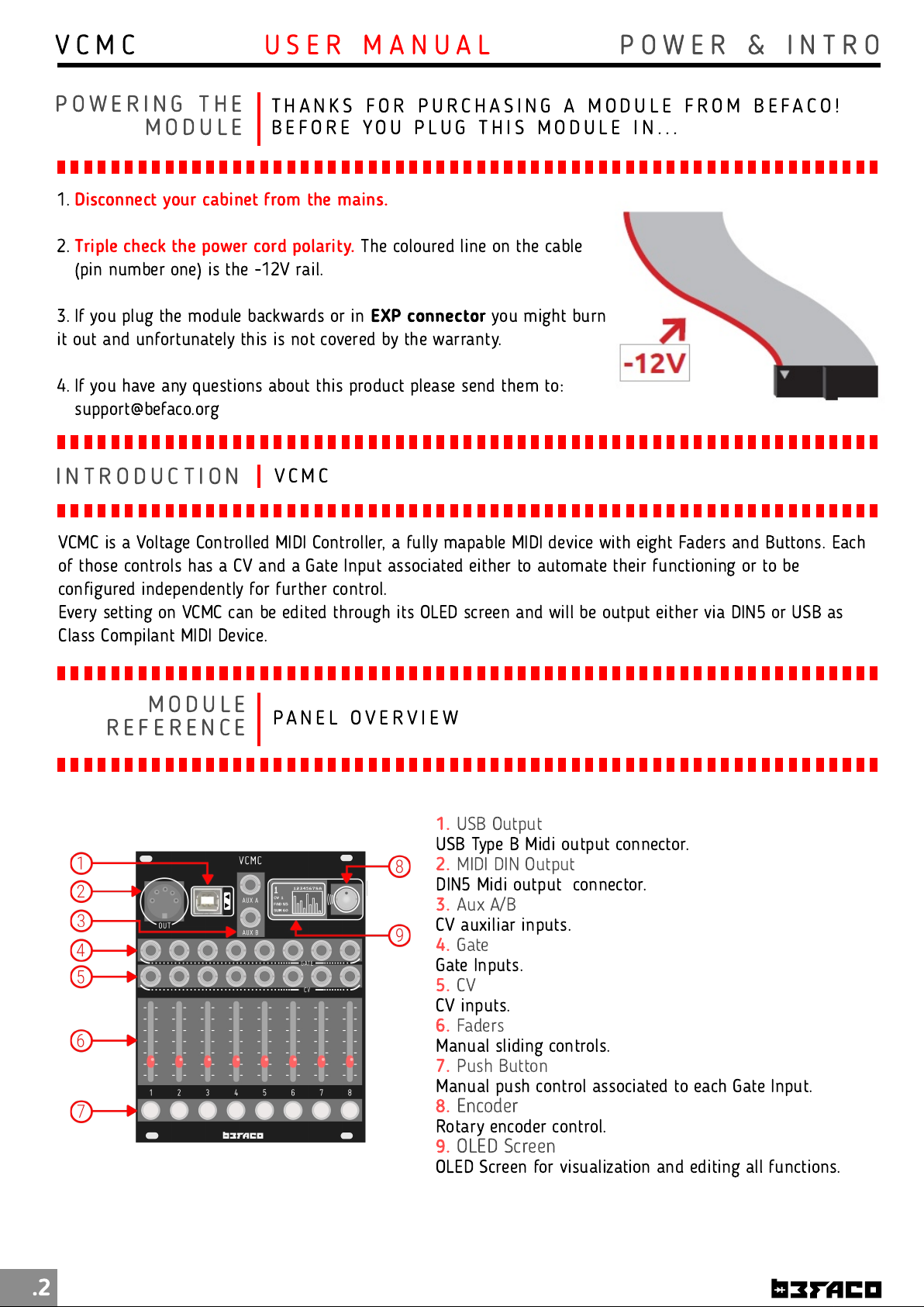
1.
USB Type B Midi output connector.
2.
DIN5 Midi output connector.
3.
CV auxiliar inputs.
4.
Gate Inputs.
5.
CV inputs.
6.
Manual sliding controls.
7.
Manual push control associated to each Gate Input.
8.
Rotary encoder control.
9.
OLED Screen for visualization and editing all functions.
USB Output
MIDI DIN Output
Aux A/B
Gate
CV
Faders
Push Button
Encoder
OLED Screen
.2
Page 5
V C M C
U S E R M A N U A L
F I R S T S T E P S
S TA R T I N G
C O N N E C T I N G T H E U N I T T O E X T E R N A L G E A R
W I T H V C M C
There are two main MIDI connection s in VCM C: USB and DIN5. Both con n ection s send every MIDI
message generated by the module, choosing each one depen ding on the devi ce you will be
con trolli ng. Let's take a deeper look:
US B
The USB port is the most conveni ent way to con n ect VCMC to a
com puter. Just plug a USB Type B cable from VCMC to a free USB port of
your computer and the module should be automatically recognized as a
MI DI Device. You will be able to select it on the MI DI connecti ons of your
DAW or any other software th at supports MIDI.
If you h ave USB Host devi ces, you can use this port with it in the same
way we did with the computer.
DI N 5
Most of th e extern al gear out th ere uses DI N 5 connecti ons for MIDI
con trol. I f you want to con trol your external gear with VCMC, just plug a
standard MIDI DI N cable from VCMC´s DI N 5 Out port to your devi ce´s
MI DI Input.
B A S I C
B L O C K S & P E R F O R M A N C E S C R E E N
S T R U C T U R E
In VCMC, you have a variety of
di fferen t con trols an d connection s
capable of sen ding MIDI to your
external gear. To make it as clear and
friendly as possible, th e module is
divided in eight fun ctional blocks.
A block is con formed by a set of
con trols th at can be configured to
sen d different MIDI messages.
Basically, each block contai n s a CV
Input, a Fader and a Gate In put wi th
a linked Push Button.
The activi ty of each block is displayed
on th e Performan ce Screen.
VCMC Block
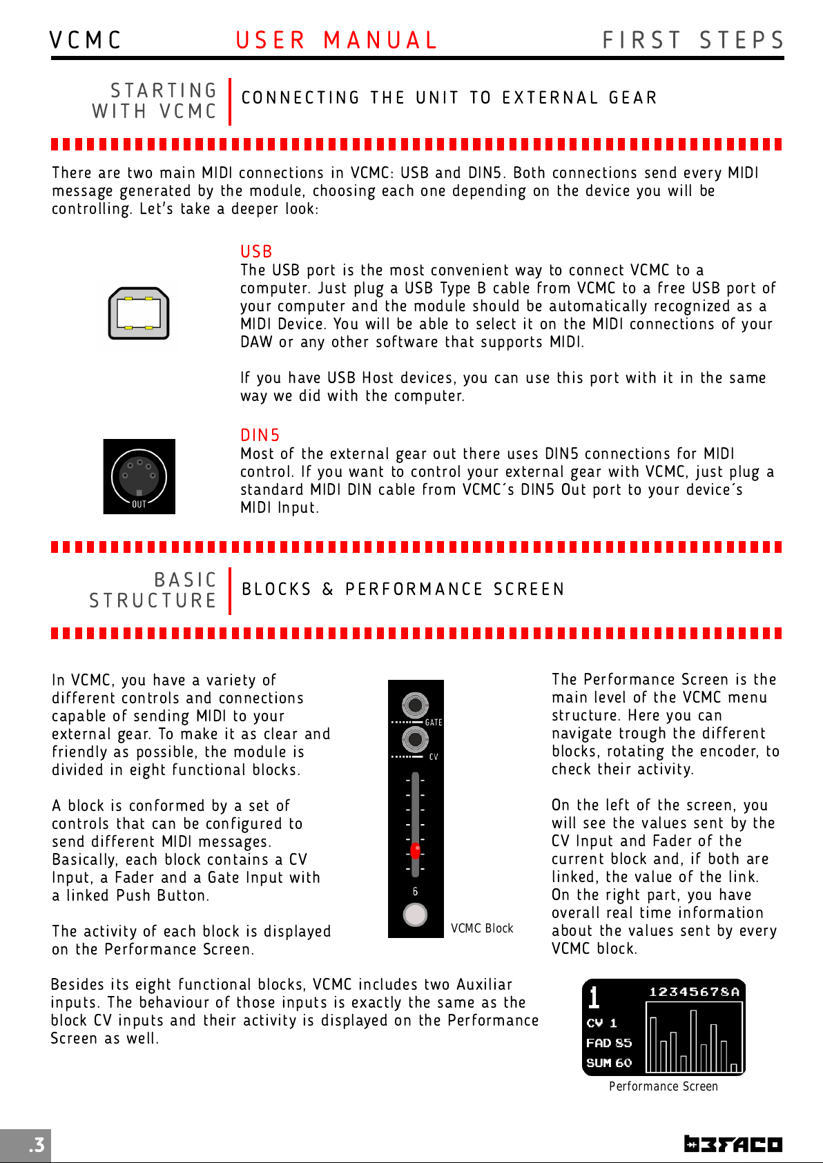
The Perform an ce Screen is the
main level of the VCMC menu
structure. Here you can
navigate trough th e different
blocks, rotati ng th e en coder, to
check their activi ty.
On th e left of th e screen, you
will see the values sent by th e
CV In put and Fader of th e
current block and, if both are
li n ked, th e value of the li n k.
On th e righ t part, you have
overall real ti m e inform ati on
about the values sent by every
VCMC block.
Besides its eight function al blocks, VCMC in cludes two Auxiliar
inputs. Th e behaviour of those in puts is exactly th e same as th e
block CV inputs and their activi ty is displayed on the Perform ance
Screen as well.
.3
Performance Screen
Page 6
V C M C
C O N F I G U R I N G V C M CU S E R M A N U A L
S E T T I N G T H E
C O N F I G U R A T I O N S C R E E N
B L O C K S
Click th e en coder on a selected block to configure it.
In this menu you can navigate th rough th e different controls of the selected block. Access them
by clicki ng th e en coder button. For each control you will be able to map MIDI Messages, MI DI
Chann el an d in put and output ranges.
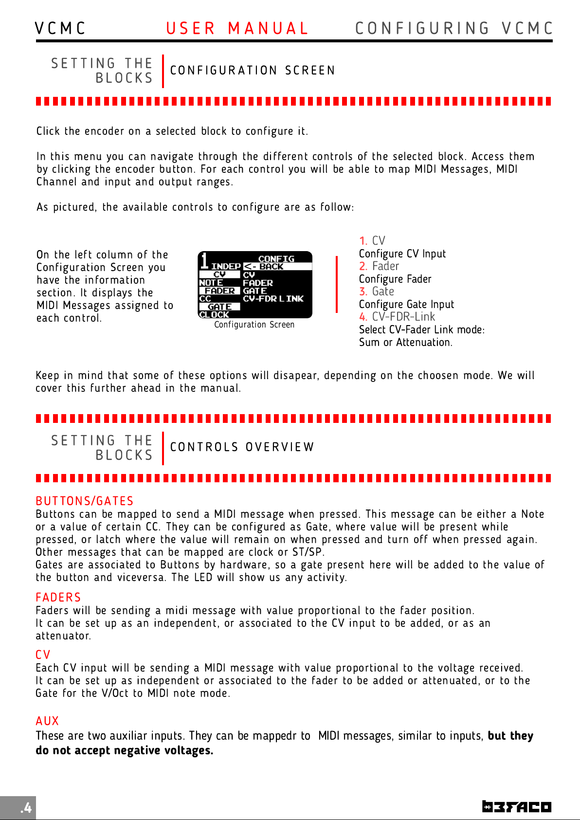
As pictured, th e available con trols to configure are as follow:
1.
CV
On th e left column of the
Con figuration Screen you
have the information
section. It displays th e
MI DI Messages assigned to
each control.
Configuration Screen
Configure CV Input
2.
Fader
Configure Fader
3.
Gate
Configure Gate Input
4.
CV-FDR-Link
Select CV-Fader Link mode:
Sum or Attenuation.
Keep in mi n d that some of these options will disapear, depending on the choosen mode. We will
cover this further ahead in the manual.
S E T T I N G T H E
C O N T R O L S O V E R V I E W
B L O C K S
BU T TON S /G ATE S
Buttons can be mapped to send a MIDI message when pressed. This message can be ei th er a N ote
or a value of certain CC. They can be configured as Gate, where value will be presen t while
pressed, or latch where the value will remain on when pressed and turn off when pressed again.
Other m essages that can be mapped are clock or ST/SP.
Gates are associated to Buttons by hardware, so a gate presen t here will be added to the value of
the button and viceversa. The LED will show us any activi ty.
FAD ER S
Faders will be sendi ng a m i di m essage with value proporti onal to the fader posi ti on.
It can be set up as an independent, or associated to the CV input to be added, or as an
attenuator.
CV
Each CV input will be sending a MI DI message with value proportional to th e voltage recei ved.
It can be set up as in depen dent or associated to the fader to be added or attenuated, or to th e
Gate for the V/Oct to MIDI n ote mode.
AU X
These are two auxiliar inputs. They can be mappedr to MIDI messages, similar to inputs,
do not accept negative voltages.
.4
but they
Page 7
V C M C
C O N F I G U R I N G V C M CU S E R M A N U A L
S E T T I N G T H E
C V E D I T
B L O C K S
Each VCM C control has its own con figuration men u where you
can configure its behaviour. Let's start wi th the CV Inputs.
From the Perform ance Screen, select a block and press th e
encoder to en ter into the main Configurati on Screen. Go to CV
and press the encoder again to enter i n to the CV Edi t Menu.
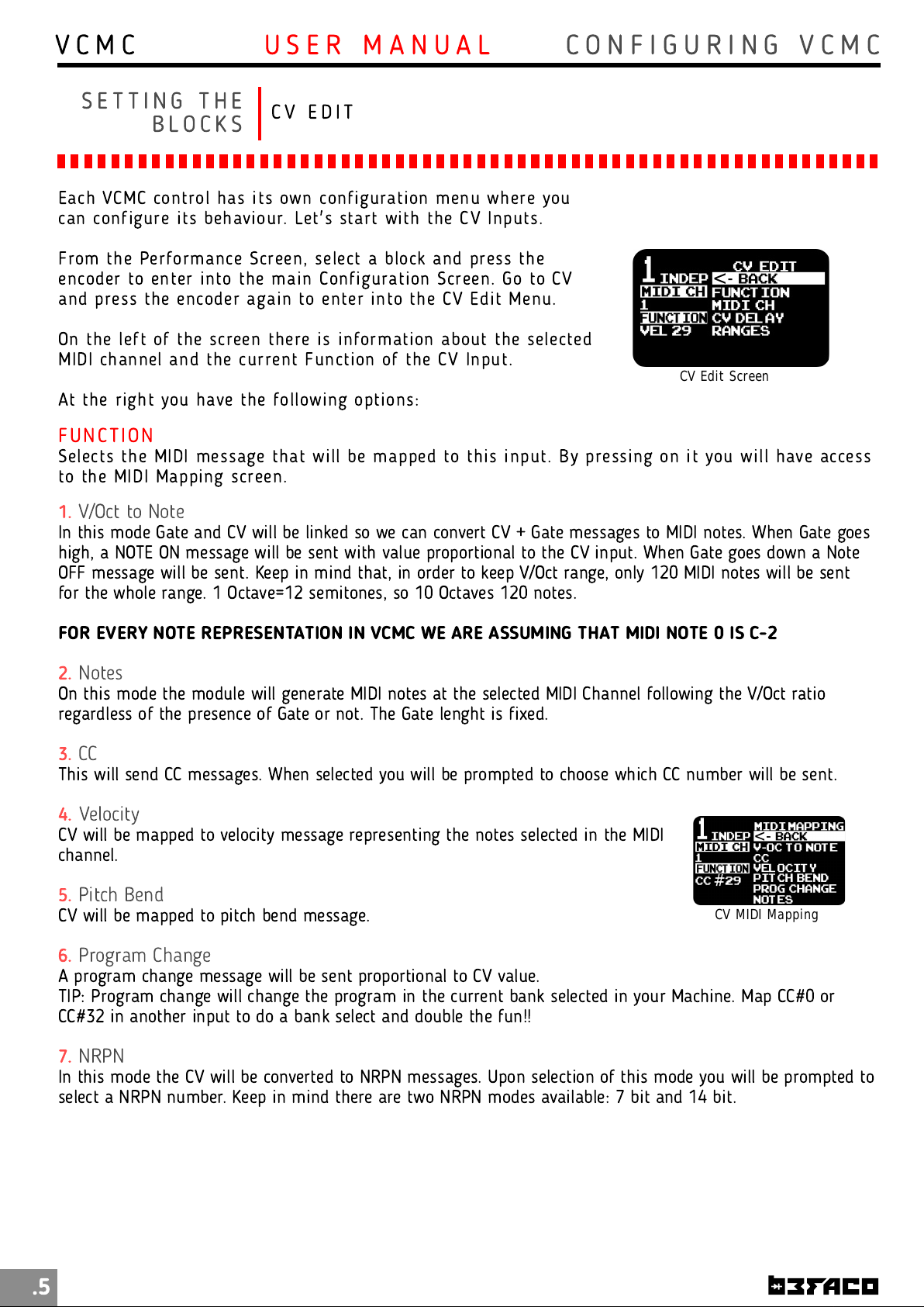
On th e left of th e screen there is information about the selected
MI DI chan n el and the current Function of th e CV Input.
At th e righ t you have th e following opti ons:
FU N C TI O N
Selects the MIDI m essage th at wi ll be mapped to th i s input. By pressi ng on it you will have access
to th e MIDI Mappi ng screen.
1.
V/Oct to Note
In this mode Gate and CV will be linked so we can convert CV + Gate messages to MIDI notes. When Gate goes
high, a NOTE ON message will be sent with value proportional to the CV input. When Gate goes down a Note
OFF message will be sent. Keep in mind that, in order to keep V/Oct range, only 120 MIDI notes will be sent
for the whole range. 1 Octave=1 2 semitones, so 10 Octaves 120 notes.
CV Edit Screen
FOR EVERY NOTE REPRESENTATION IN VCMC WE ARE ASSUMING THAT MIDI NOTE 0 IS C-2
2.
Notes
On this mode the module will generate MIDI notes at the selected MIDI Channel following the V/Oct ratio
regardless of the presence of Gate or not. The Gate lenght is fixed.
3.
CC
This will send CC messages. When selected you will be prompted to choose which CC number will be sent.
4.
Velocity
CV will be mapped to velocity message representing the notes selected in the MIDI
channel.
5.
Pitch Bend
CV will be mapped to pitch bend message.
6.
Program Change
A program change message will be sent proportional to CV value.
TIP: Program change will change the program in the current bank selected in your Machine. Map CC#0 or
CC#32 in another input to do a bank select and double the fun!!
7.
NRPN
In this mode the CV will be converted to NRPN messages. Upon selection of this mode you will be prompted to
select a NRPN number. Keep in mind there are two NRPN modes available: 7 bit and 14 bit.
CV MIDI Mapping
.5
Page 8
V C M C
C O N F I G U R I N G V C M CU S E R M A N U A L
S E T T I N G T H E
C V E D I T
B L O C K S
MI D I CH AN N EL
Selects MIDI Chan n el for th is CV Input.
CV DE LAY
Set a delay on the CV readi ng. Specially useful on V/Oct mode. As som e sequencers have some
delay between setting th e gate high an d sending th e CV, with this feature you will avoid sendi ng
old messages.
RA N G ES
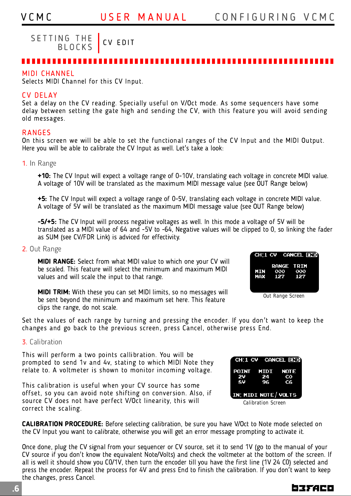
On th i s screen we will be able to set the functional ranges of th e CV I nput an d the MI DI Output.
Here you will be able to calibrate the CV Input as well. Let's take a look:
1.
In Range
+10:
The CV Input will expect a voltage range of 0-10V, translating each voltage in concrete MIDI value.
A voltage of 1 0V will be translated as the maximum MIDI message value (see OUT Range below)
+5:
The CV Input will expect a voltage range of 0-5V, translating each voltage in concrete MIDI value.
A voltage of 5V will be translated as the maximum MIDI message value (see OUT Range below)
-5/+5:
translated as a MIDI value of 64 and -5V to -64, Negative values will be clipped to 0, so linking the fader
as SUM (see CV/FDR Link) is adviced for effectivity.
2.
Out Range
MIDI RANGE:
be scaled. This feature will select the minimum and maximum MIDI
values and will scale the input to that range.
MIDI TRIM:
be sent beyond the minimum and maximum set here. This feature
clips the range, do not scale.
Set th e values of each range by turn i ng an d pressing th e en coder. If you don't want to keep th e
changes and go back to the previous screen, press Can cel, otherwise press En d.
3.
Calibration
This wi ll perform a two points callibration . You will be
prompted to send 1 v and 4v, stating to whi ch MIDI Note they
relate to. A voltmeter is shown to mon itor in coming voltage.
This cali bration is useful when your CV source has some
offset, so you can avoi d n ote shifti ng on conversion . Also, if
source CV does not have perfect V/Oct linearity, th i s will
correct th e scaling.
The CV Input will process negative voltages as well. In this mode a voltage of 5V will be
Select from what MIDI value to which one your CV will
With these you can set MIDI limits, so no messages will
Calibration Screen
Out Range Screen
CALIBRATION PROCEDURE:
the CV Input you want to calibrate, otherwise you will get an error message prompting to activate it.
Once done, plug the CV signal from your sequencer or CV source, set it to send 1 V (go to the manual of your
CV source if you don't know the equivalent Note/Volts) and check the voltmeter at the bottom of the screen. If
all is well it should show you C0/1V, then turn the encoder till you have the first line (1V 24 C0) selected and
press the encoder. Repeat the process for 4V and press End to finish the calibration. If you don't want to keep
the changes, press Cancel.
Before selecting calibration, be sure you have V/Oct to Note mode selected on
.6
Page 9
V C M C
C O N F I G U R I N G V C M CU S E R M A N U A L
S E T T I N G T H E
FA D E R E D I T
B L O C K S
From Performance Screen , select a block an d press th e en coder
to enter in the mai n Con figuration Screen . Go to Fader and
press the encoder again to enter into th e Fader Edit Menu.
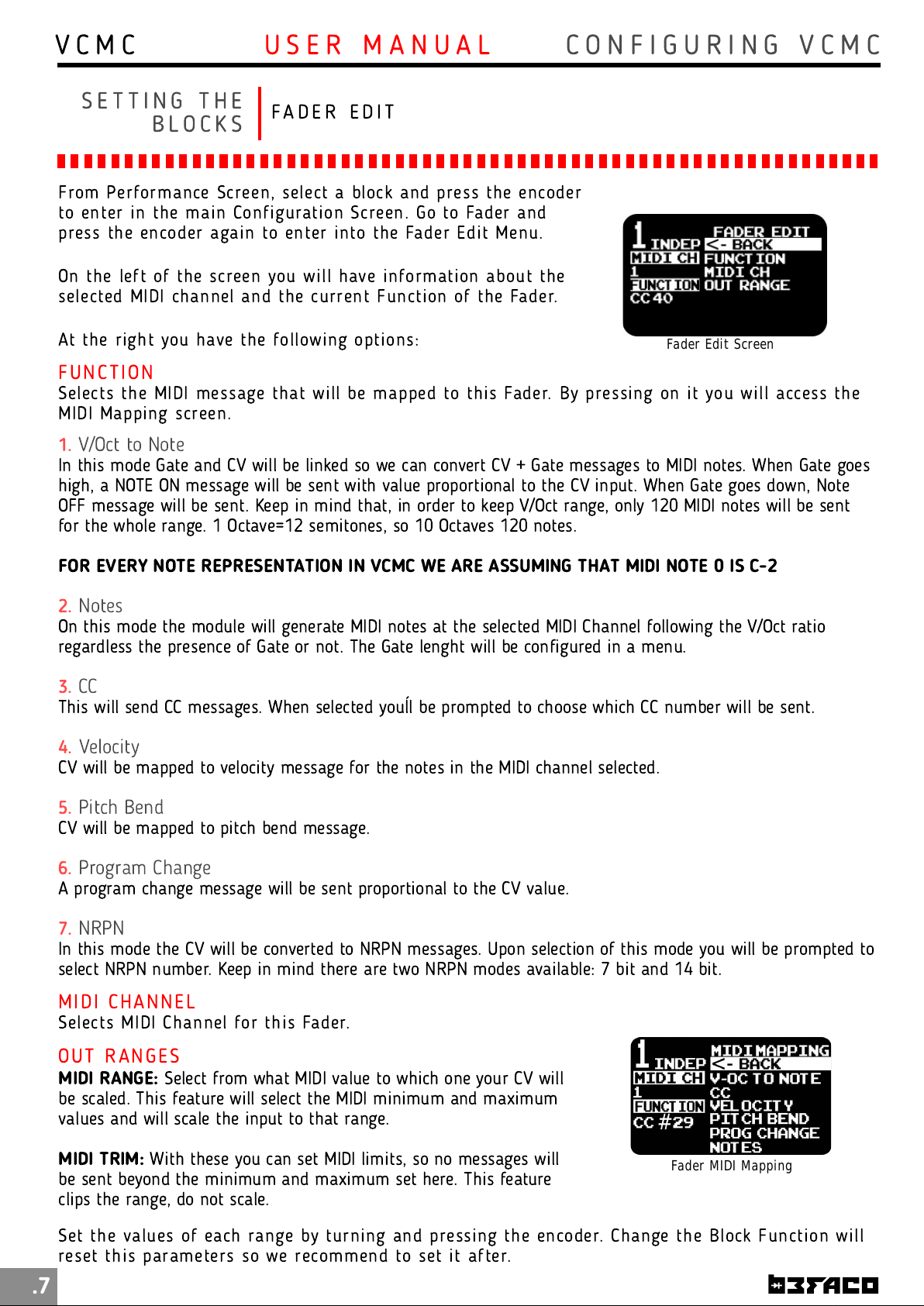
On th e left of th e screen you wi ll have in formati on about th e
selected MI DI ch annel and the current Functi on of the Fader.
At th e righ t you have th e following opti ons:
FU N C TI O N
Selects the MIDI m essage th at wi ll be mapped to th i s Fader. By pressing on i t you will access th e
MI DI Mapping screen.
1.
V/Oct to Note
In this mode Gate and CV will be linked so we can convert CV + Gate messages to MIDI notes. When Gate goes
high, a NOTE ON message will be sent with value proportional to the CV input. When Gate goes down, Note
OFF message will be sent. Keep in mind that, in order to keep V/Oct range, only 120 MIDI notes will be sent
for the whole range. 1 Octave=1 2 semitones, so 10 Octaves 120 notes.
Fader Edit Screen
FOR EVERY NOTE REPRESENTATION IN VCMC WE ARE ASSUMING THAT MIDI NOTE 0 IS C-2
2.
Notes
On this mode the module will generate MIDI notes at the selected MIDI Channel following the V/Oct ratio
regardless the presence of Gate or not. The Gate lenght will be configured in a menu.
3.
CC
This will send CC messages. When selected youĺl be prompted to choose which CC number will be sent.
4.
Velocity
CV will be mapped to velocity message for the notes in the MIDI channel selected.
5.
Pitch Bend
CV will be mapped to pitch bend message.
6.
Program Change
A program change message will be sent proportional to the CV value.
7.
NRPN
In this mode the CV will be converted to NRPN messages. Upon selection of this mode you will be prompted to
select NRPN number. Keep in mind there are two NRPN modes available: 7 bit and 14 bit.
MI D I CH AN N EL
Selects MIDI Chan n el for th is Fader.
OU T RAN G ES
MIDI RANGE:
be scaled. This feature will select the MIDI minimum and maximum
values and will scale the input to that range.
MIDI TRIM:
be sent beyond the minimum and maximum set here. This feature
clips the range, do not scale.
Set th e values of each range by turn i ng an d pressing th e en coder. Change the Block Function will
reset this parameters so we recommen d to set i t after.
Select from what MIDI value to which one your CV will
With these you can set MIDI limits, so no messages will
Fader MIDI Mapping
.7
Page 10
V C M C
C O N F I G U R I N G V C M CU S E R M A N U A L
S E T T I N G T H E
G A T E E D I T
B L O C K S
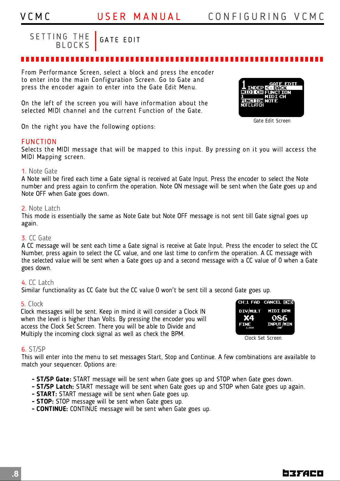
From Performance Screen , select a block an d press th e en coder
to enter in to the main Configuration Screen. Go to Gate and
press the encoder again to enter into th e Gate Edit Menu.
On th e left of th e screen you wi ll have in formati on about th e
selected MI DI ch annel and the current Functi on of the Gate.
Gate Edit Screen
On th e righ t you have th e following opti ons:
FU N C TI O N
Selects the MIDI m essage th at wi ll be mapped to th i s input. By pressi ng on it you will access the
MI DI Mapping screen.
1.
Note Gate
A Note will be fired each time a Gate signal is received at Gate Input. Press the encoder to select the Note
number and press again to confirm the operation. Note ON message will be sent when the Gate goes up and
Note OFF when Gate goes down.
2.
Note Latch
This mode is essentially the same as Note Gate but Note OFF message is not sent till Gate signal goes up
again.
3.
CC Gate
A CC message will be sent each time a Gate signal is receive at Gate Input. Press the encoder to select the CC
Number, press again to select the CC value, and one last time to confirm the operation. A CC message with
the selected value will be sent when a Gate goes up and a second message with a CC value of 0 when a Gate
goes down.
4.
CC Latch
Similar functionality as CC Gate but the CC value 0 won't be sent till a second Gate goes up.
5.
Clock
Clock messages will be sent. Keep in mind it will consider a Clock IN
when the level is higher than Volts. By pressing the encoder you will
access the Clock Set Screen. There you will be able to Divide and
Multiply the incoming clock signal as well as check the BPM.
6.
ST/SP
This will enter into the menu to set messages Start, Stop and Continue. A few combinations are available to
match your sequencer. Options are:
Clock Set Screen
.8
- ST/SP Gate:
- ST/SP Latch:
- START:
- STOP:
- CONTINUE:
START message will be sent when Gate goes up.
STOP message will be sent when Gate goes up.
START message will be sent when Gate goes up and STOP when Gate goes down.
START message will be sent when Gate goes up and STOP when Gate goes up again.
CONTINUE message will be sent when Gate goes up.
Page 11
V C M C
C O N F I G U R I N G V C M CU S E R M A N U A L
S E T T I N G T H E
C V / F A D E R L I N K
B L O C K S
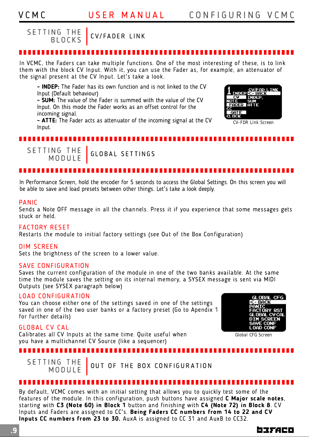
In VCMC, the Faders can take multiple fun cti ons. One of th e most interesting of th ese, is to link
them wi th th e block CV Input. Wi th it, you can use th e Fader as, for example, an attenuator of
the signal present at th e CV I n put. Let's take a look.
- INDEP:
Input (Default behaviour)
- SUM:
Input. On this mode the Fader works as an offset control for the
incoming signal.
- ATTE:
Input.
S E T T I N G T H E
The Fader has its own function and is not linked to the CV
The value of the Fader is summed with the value of the CV
The Fader acts as attenuator of the incoming signal at the CV
G LO B A L S E T T I N G S
CV-FDR Link Screen
M O D U L E
In Performance Screen, hold the encoder for 5 seconds to access the Global Settings. On this screen you will
be able to save and load presets between other things. Let's take a look deeply.
PAN I C
Sen ds a Note OFF message in all the ch annels. Press it if you experi ence that som e messages gets
stuck or held.
FAC TO RY RES E T
Restarts the module to ini ti al factory settings (see Out of th e Box Configuration)
DI M SC RE EN
Sets the brightness of th e screen to a lower value.
SAVE CO N FI GU R ATI ON
Saves the current configuration of the module in one of th e two banks available. At the sam e
time th e module saves the setting on its internal mem ory, a SYSEX message is sen t vi a MI DI
Outputs (see SYSEX paragraph below)
LO AD CO N FI GU R ATI ON
You can choose eith er one of the settings saved in one of the setti ngs
saved in one of th e two user ban ks or a factory preset (Go to Apendi x 1
for furth er details)
GLO BAL CV CA L
Calibrates all CV I n puts at the same time. Quite useful when
you have a m ultichannel CV Source (li ke a sequen cer)
Global CFG Screen
S E T T I N G T H E
O U T O F T H E B O X C O N F I G U R A T I O N
M O D U L E
By default, VCMC com es wi th an ini ti al setting th at allows you to quickly test some of th e
features of th e module. In this con figuration , push buttons have assigned
starting with
Inputs and Faders are assigned to CC's.
In puts CC numbers from 23 to 30.
C3 (N ote 60) in Block 1
button and finish i ng wi th
Being Faders CC numbers from 1 4 to 22 and CV
AuxA is assigned to CC 31 and AuxB to CC32.
C4 (N ote 72) in Block 8
C Major scale notes
.9
,
. CV
Page 12
V C M C
C O N F I G U R I N G V C M CU S E R M A N U A L
M A N A G I N G
S Y S E X F U N C T I O N I N G
P R E S E T S
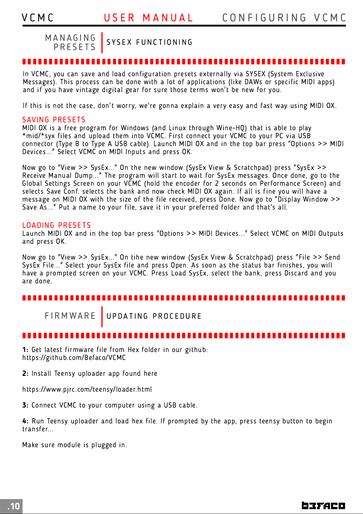
In VCMC, you can save an d load configuration presets extern ally via SYSEX (System Exclusive
Messages). Th i s process can be don e with a lot of application s (like DAWs or speci fic MIDI apps)
and if you have vintage digi tal gear for sure those term s won't be new for you.
If this is not the case, don 't worry, we're gonna explain a very easy and fast way usi ng MIDI OX.
SAVI N G PRE SE TS
MI DI OX is a free program for Wi n dows (and Lin ux through Wine-HQ) that i s able to play
*mi d/*syx files and upload them i n to VCM C. First connect your VCMC to your PC vi a USB
con n ector (Type B to Type A USB cable). Laun ch MI DI OX and in the top bar press "Option s >> MIDI
Devices..." Select VCMC on MI DI I n puts and press OK.
Now go to "View >> SysEx..." On th e new window (SysEx View & Scratchpad) press "SysEx >>
Receive Manual Dump..." Th e program wi ll start to wai t for SysEx messages. Once done, go to the
Global Settings Screen on your VCMC (hold the encoder for 2 seconds on Performan ce Screen) and
selects Save Conf. selects th e bank an d now ch eck MIDI OX again. If all is fine you will have a
message on MIDI OX with th e size of the fi le recei ved, press Done. N ow go to "Di splay Window >>
Save As..." Put a nam e to your file, save it in your preferred folder and that's all.
LO ADI N G PRE SE TS
Laun ch MI DI OX an d in th e top bar press "Opti ons >> MIDI Devices..." Select VCMC on MIDI Outputs
and press OK.
Now go to "View >> SysEx..." On ti h e new window (SysEx View & Scratchpad) press "File >> Sen d
SysEx File..." Select your SysEx fi le and press Open. As soon as the status bar fin i shes, you will
have a prompted screen on your VCMC. Press Load SysEx, select th e bank, press Di scard an d you
are done.
F I R M WA R E
1 :
Get latest firmware file from Hex folder in our github:
https://gi th ub. com/Befaco/VCMC
2:
Install Teen sy uploader app foun d h ere
https://www.pjrc.com /teensy/loader.h tm l
U P D A T I N G P R O C E D U R E
3:
Con n ect VCM C to your computer using a USB cable.
4:
Run Teensy uploader and load hex file. If prom pted by the app, press teen sy button to begin
transfer...
Make sure module is plugged in.
.10
Page 13
V C M C
U S E R M A N U A L
E X T R A S
M I S C E L L A N E A
* Si ze
* Depth
* +1 2v:
* -1 2v:
: 20HP
: 30mm
65mA
8mA
S P E C S & C R E D I T S
This module is th e result of loads of hours of work, love and care. It
would have been i m posible to finish wi th out the help of beta testers,
loving friends, people from Hangar's open thursdays providing very
strong opin i ons and the wh ole Befaco team kicking asses as usual.
Hardware design, testing, docum entation , graph i c user interface and
many funky extra features: Befaco team.
Caring, relentless, tireless beta testers: Jon "Jessica Fletcher"
Bernabeu, Miguel Cruz, Jose A. Cabrera, Miguel Eedl, Lui s Bot, Ben
wilson aka Divkid and Ziv Eli raz aka Loopop.
Firmware coding, common sense and über-cold beers:
Sergi o Retamero (sergio.retam ero@gm ai l.com )
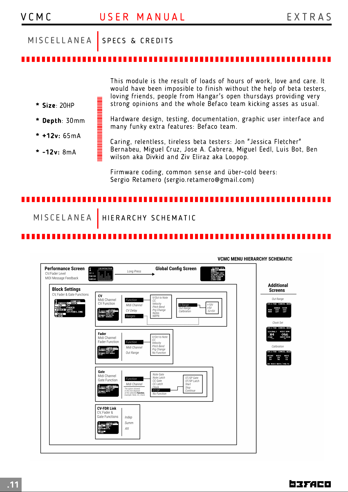
M I S C E L A N E A
H I E R A R C H Y S C H E M A T I C
.11
Page 14
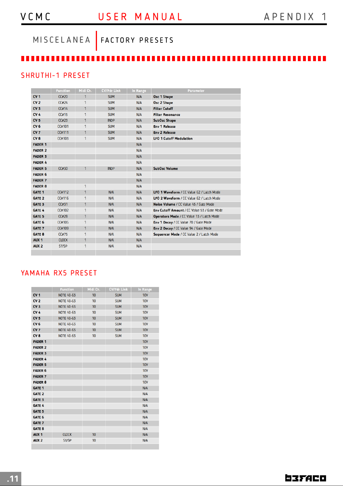
V C M C
A P E N D I X 1U S E R M A N U A L
M I S C E L A N E A
SH R U TH I -1 P RES E T
FA C T O R Y P R E S E T S
YA M AH A R X5 PRE SE T
.11
 Loading...