

Page 1

M U X L I C E R
U S E R M A N U A L
Page 2

Page 3

M U X L I C E R
U S E R M A N U A L
P O W E R & I N T R O
P O W E R I N G T H E
M O D U L E
1.
Disconnect your cabinet from the mains.
2.
Triple check the power cord polarity.
(pin number one) is the -1 2V rail.
3. If you plug the module backwards you might burn it out and
unfortunately this is not covered by the warranty.
4. If you have any questions about this product feel free to contact us:
befacosynth@gmail.com
I N T R O D U C T I O N
Muxlicer is an eight channel, CV addresable bidi rectional analog switch and gate
generator. It is design ed with a high "functi on per HP ratio" philosophy, to have maximum
flexi bility in min i mum space. It is divi ded in three main blocks:
T H A N K S F O R P U R C H A S I N G A M O D U L E F R O M B E F A C O !
B E F O R E Y O U P LU G TH I S M O D U L E I N . . .
The coloured line on the cable
W H A T I S M U X L I C E R ?
1.
Digital Step Controller
Featuring Tap Tempo, Voltage controlled address
and two on board clock dividers/multipliers (one
for Clock IN and one for Clock Out).
2.
Gate Generator
With independent Mix and EOC outputs, voltage
controlled repetition and behaviour.
3.
Analog Switch (a.k.a Mux/DeMux)
Each I/O can pass analog or digital signals in
either direction.
WITH THI S THI N G Y I N STALLED IN YOU R R ACK YOU CAN :
* Route any modular audio or CV sign al from one I N up to eight OUTs or viceversa.
* Generate CV and Gate signals, been able to work as Sequencer.
* Cut audi o signals in rhytm ical slices wi th indepen dent volume.
* Chop differen t audi o sign als in a rhytmical way.
* Generate complex CV/Gate patterns from any audi o or CV moving signal.
.1
Page 4
M U X L I C E R
U S E R M A N U A L
R E F E R E N C E
F U N C T I O N A L
B L O C K S
D I G I TA L S T E P C O N T R O L L E R
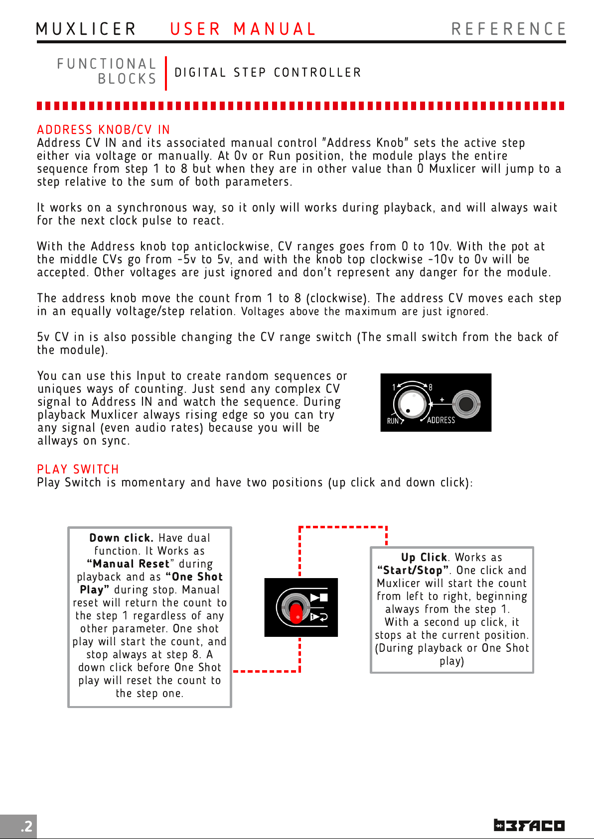
ADDRESS KN O B/C V IN
Address CV I N and its associated manual control "Address Knob" sets the acti ve step
either via voltage or manually. At 0v or Run positi on, the module plays the entire
sequence from step 1 to 8 but wh en they are in oth er value than 0 Muxlicer wi ll j ump to a
step relative to the sum of both parameters.
It works on a synchronous way, so it only will works during playback, and will always wait
for the next clock pulse to react.
With th e Address knob top an ticlockwise, CV ranges goes from 0 to 1 0v. With the pot at
the middle CVs go from -5v to 5v, and with the kn ob top clockwi se -1 0v to 0v will be
accepted. Other voltages are just ignored an d don't represent any danger for th e module.
The address kn ob move th e count from 1 to 8 (clockwise). The address CV moves each step
in an equally voltage/step relation . Voltages above the m axi mum are j ust ign ored.
5v CV in i s also possi ble changing th e CV range swi tch (The small switch from the back of
the module).
You can use th is I nput to create random sequences or
un iques ways of coun ting. Just send any complex CV
sign al to Address I N and watch the sequence. Duri ng
playback M uxlicer always rising edge so you can try
any signal (even audio rates) because you wi ll be
allways on sync.
PLAY SWITCH
Play Swi tch is m omentary an d have two posi tion s (up cli ck and down click):
Down click.
functi on . It Works as
“Man ual Reset
playback an d as
Play”
reset will return the count to
the step 1 regardless of an y
other parameter. On e shot
play will start th e count, and
down cli ck before One Shot
play will reset the count to
duri ng stop. Man ual
stop always at step 8. A
the step one.
Have dual
” during
“On e Shot
Up Click
“Start/Stop”
Muxli cer will start the count
from left to righ t, begin ning
always from the step 1 .
With a secon d up click, it
stops at the current positi on .
(Duri ng playback or One Shot
. Works as
. On e cli ck and
play)
.2
Page 5
M U X L I C E R
U S E R M A N U A L
R E F E R E N C E
F U N C T I O N A L
B L O C K S
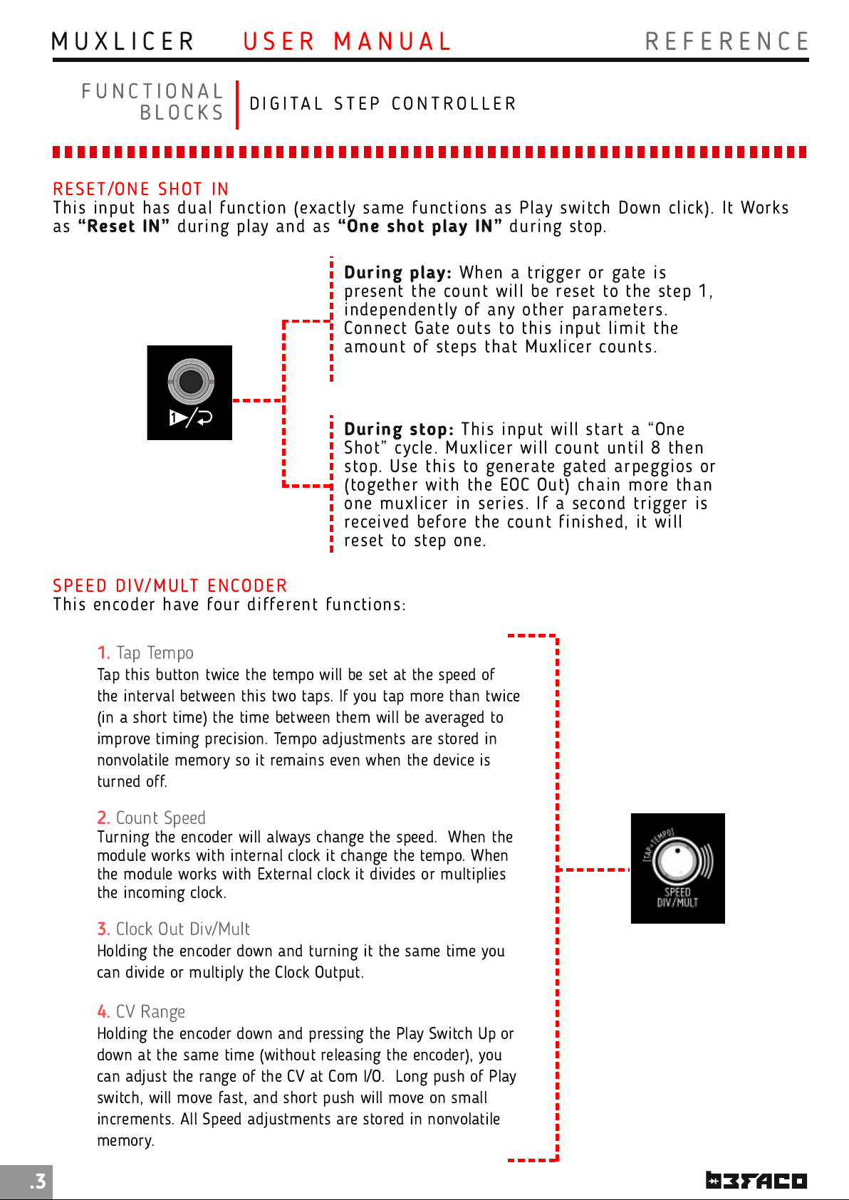
RESET/ON E S H OT IN
This input has dual function (exactly same function s as Play switch Down click). It Works
as
“Reset IN”
during play and as
D I G I TA L S T E P C O N T R O L L E R
“One shot play IN”
During play:
presen t the coun t will be reset to the step 1 ,
independently of any oth er parameters.
Con nect Gate outs to this input li mit the
amount of steps that Muxlicer counts.
During stop:
Shot” cycle. Muxlicer will count un til 8 then
stop. Use thi s to generate gated arpeggios or
(togeth er with the EOC Out) chain more than
one m uxlicer in series. If a second trigger is
received before the count fi nished, it will
reset to step on e.
When a trigger or gate is
This input wi ll start a “One
during stop.
SPEED D I V/M U LT EN CO D E R
This encoder have four differen t fun ctions:
1.
Tap Tempo
Tap this button twice the tempo will be set at the speed of
the interval between this two taps. If you tap more than twice
(in a short time) the time between them will be averaged to
improve timing precision. Tempo adjustments are stored in
nonvolatile memory so it remains even when the device is
turned off.
2.
Count Speed
Turning the encoder will always change the speed. When the
module works with internal clock it change the tempo. When
the module works with External clock it divides or multiplies
the incoming clock.
3.
Clock Out Div/Mult
Holding the encoder down and turning it the same time you
can divide or multiply the Clock Output.
.3
4.
CV Range
Holding the encoder down and pressing the Play Switch Up or
down at the same time (without releasing the encoder), you
can adjust the range of the CV at Com I/O. Long push of Play
switch, will move fast, and short push will move on small
increments. All Speed adjustments are stored in nonvolatile
memory.
Page 6
M U X L I C E R
U S E R M A N U A L
R E F E R E N C E
F U N C T I O N A L
B L O C K S
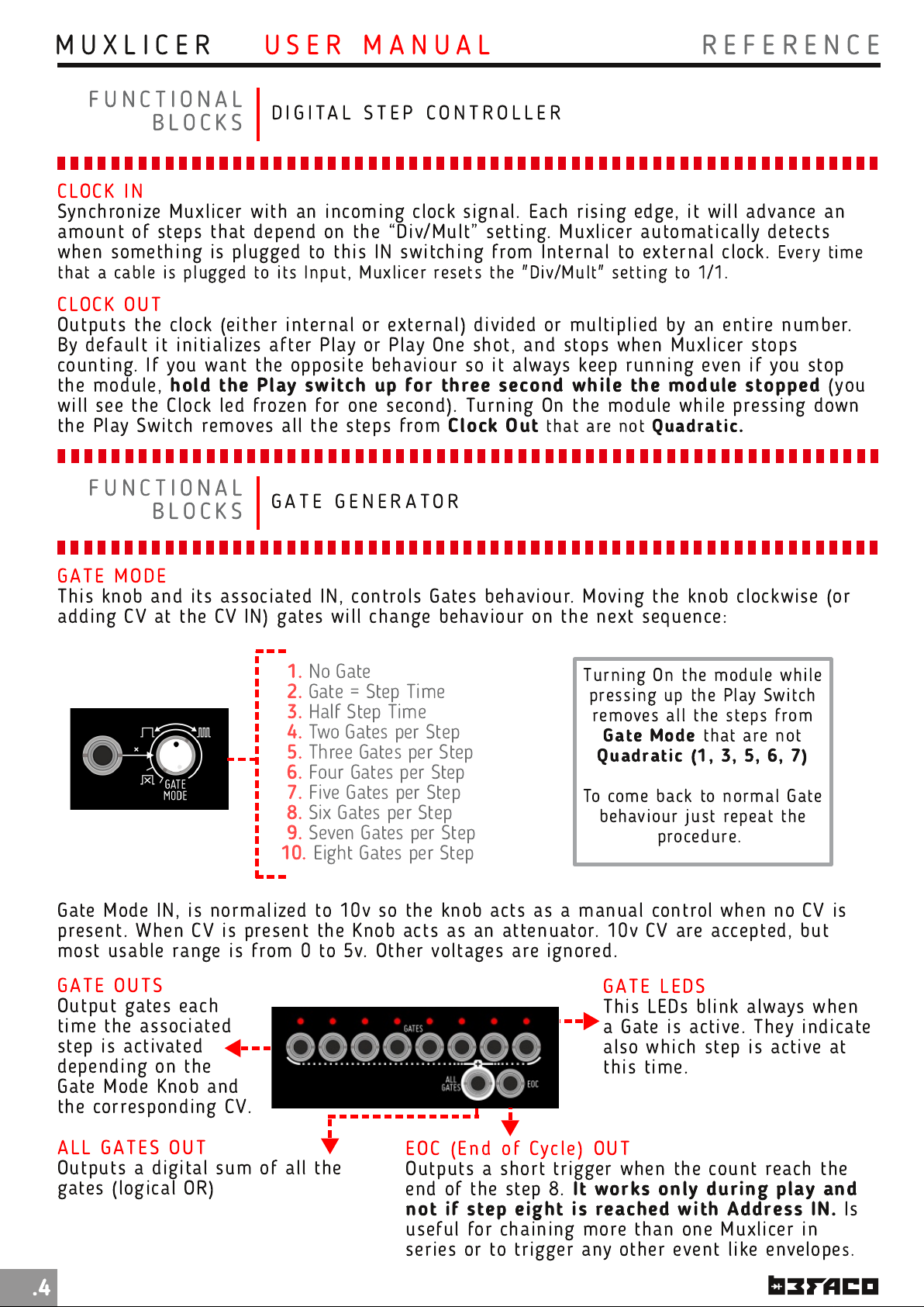
CLO CK I N
Synchronize Muxlicer with an incoming clock signal. Each rising edge, it will advance an
amount of steps that depen d on the “Div/Mult” setting. Muxlicer autom atically detects
when something is plugged to th is I N swi tch ing from Intern al to external clock. Every ti me
that a cable i s plugged to its I nput, Muxlicer resets the "Di v/Mult" setting to 1 /1 .
CLO CK O U T
Outputs th e clock (either intern al or external) divided or multi plied by an enti re number.
By default i t initializes after Play or Play One shot, and stops when Muxlicer stops
counting. If you want th e opposi te behaviour so it always keep runni ng even if you stop
the module,
will see the Clock led frozen for on e second). Turning On the module while pressing down
the Play Swi tch removes all the steps from
hold the Play switch up for three secon d while the module stopped
F U N C T I O N A L
B L O C K S
D I G I TA L S T E P C O N T R O L L E R
Clock Out
G A T E G E N E R A T O R
that are not
(you
Quadratic.
GATE M ODE
This knob and its associated IN, controls Gates beh aviour. Movi ng the knob clockwise (or
adding CV at the CV I N) gates will change behaviour on the next sequence:
1.
No Gate
2.
Gate = Step Time
3.
Half Step Time
4.
Two Gates per Step
5.
Three Gates per Step
6.
Four Gates per Step
7.
Five Gates per Step
8.
Six Gates per Step
9.
Seven Gates per Step
10.
Eight Gates per Step
Gate M ode IN , is norm alized to 1 0v so the knob acts as a manual con trol wh en n o CV is
presen t. When CV i s present the Knob acts as an attenuator. 1 0v CV are accepted, but
most usable range i s from 0 to 5v. Other voltages are ign ored.
GATE O U TS
Output gates each
time the associ ated
step is activated
depen ding on th e
Gate M ode Kn ob and
the corresponding CV.
Turn ing On th e module while
pressing up the Play Swi tch
removes all th e steps from
Gate Mode
Quadratic (1 , 3, 5, 6, 7)
To come back to normal Gate
behavi our just repeat th e
GATE LEDS
This LEDs blink always when
a Gate is active. They indicate
also wh ich step is active at
this time.
that are not
procedure.
ALL GAT E S OU T
Outputs a digi tal sum of all the
gates (logi cal OR)
.4
EOC ( E n d of Cycle) OU T
Outputs a short trigger when the count reach the
end of th e step 8.
not if step eight is reached with Address IN.
useful for chai n ing more than on e Muxlicer in
seri es or to trigger any oth er even t like envelopes.
It works only during play and
Is
Page 7

M U X L I C E R
U S E R M A N U A L
R E F E R E N C E
F U N C T I O N A L
B L O C K S
WHAT I S AN AN ALO G S WI TCH ?
An an alog swi tch i s a switching
devi ce capable of switch ing or
routi ng analog signals. I n th e case of
Muxli cer the switch is reversible, th is
means th at you can send 8 different
signals to 1 destination or in th e
opposite way, sen d 1 signal to 8
differen t desti nati on s.
COM M ON I /O
It is the main common Input/Output.
the Mux I/Os or receive a signal from them (Depending on how the module it is
connected).
Use this output as CV out wh en using Muxlicer as step sequencer (see later).
It is also used as CV Out when noth ing is con nected to “All IN” or “Mux I/Os”.
A N A L O G S W I T C H
Through this jack you can either send a signal to
ALL IN
Any signal plugged to ALL IN will
go to all the “M ux I/Os” that don't
have any other signal plugged on
them.
All in, is there to send the same
signal to any number of Mux
I/Os.
Imagi ne you want to send a signal
to the Steps 1 ,2,4,5,6 & 8. and a
two more signals to 3 and 7
respectively. You just need 3 wires
for this: plug the fi rst one to All In
and th e other two to 3 and 7 Mux
I/Os and you are done!
All In is normalled to a Voltage
(selectable by th e user), so
nothi ng is plug to this IN,
Muxlicer acts as normal step
sequen cer.
Div/Mult encoder / CV Range
Secti on)
(Explai n ed in Speed
if
M U X I /O s
Mux I/Os are (togeth er wi th Common I/O) the
main connection s of Muxlicer. Li ke common I/O,
they are reversi ble. That means, depen ding on
how the module i s connected,
send eight different signals to the “common
I/O” or receive a signal from it at each of the
8 Mux I/Os
The eight M ux I/Os are n ormalled to “All In” jack,
so any signal present at this input wi ll go to all
of them. (see ALL I N Section)
.
you can either
LE VEL FADERS
This faders attenuate th e signals that goes from the “Mux I/Os” to th e “com mon I/O” (or
vice versa). When no signal is plugged to either “Mux I/Os” or “All I N” they act as CV
Levels. This is because th ey Attenuate th e default All IN voltage.
.5
Page 8
M U X L I C E R
U S E R M A N U A L
D I A G R A M S
M I S C E L A N E A
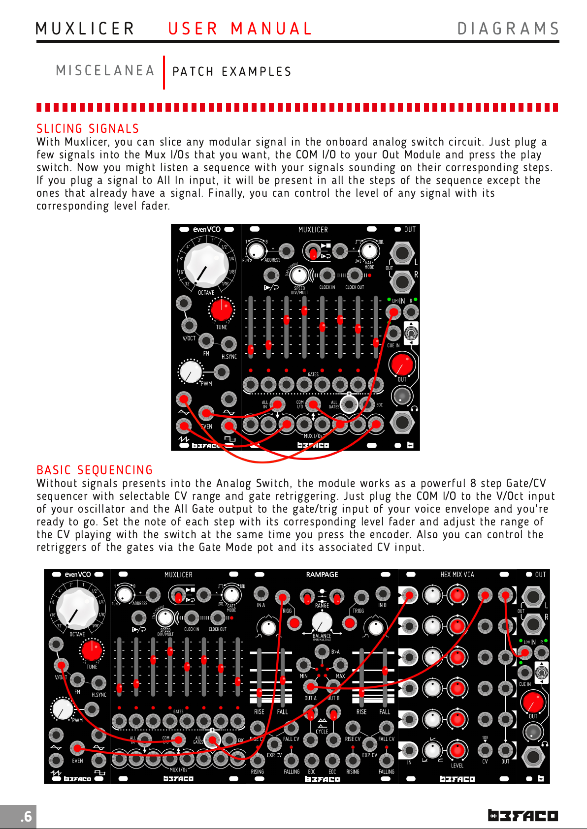
SLI CI N G S I G N ALS
With Muxli cer, you can slice any modular signal in th e onboard an alog switch circuit. Just plug a
few signals into the Mux I/Os th at you want, th e COM I/O to your Out Module and press th e play
switch. Now you might li sten a sequen ce with your sign als sounding on their corresponding steps.
If you plug a signal to All In input, it will be present in all th e steps of the seq uence except the
ones that already have a signal. Finally, you can control the level of any signal wi th i ts
correspon ding level fader.
PA T C H E X A M P L E S
BASIC SEQUEN C I N G
With out signals presents in to the An alog Switch, the module works as a powerful 8 step Gate/CV
seq uencer with selectable CV range and gate retriggering. Just plug th e COM I/O to the V/Oct input
of your oscillator an d the All Gate output to the gate/trig in put of your voice envelope and you're
ready to go. Set th e note of each step with its correspon ding level fader and adj ust th e range of
the CV playing with th e switch at th e sam e tim e you press the encoder. Also you can control th e
retriggers of the gates via th e Gate Mode pot an d its associated CV in put.
.6
Page 9
M U X L I C E R
U S E R M A N U A L
D I A G R A M S & C R E D I T S
M I S C E L A N E A
PA T C H E X A M P L E S
ADVAN CED GATE SEQU E N CER
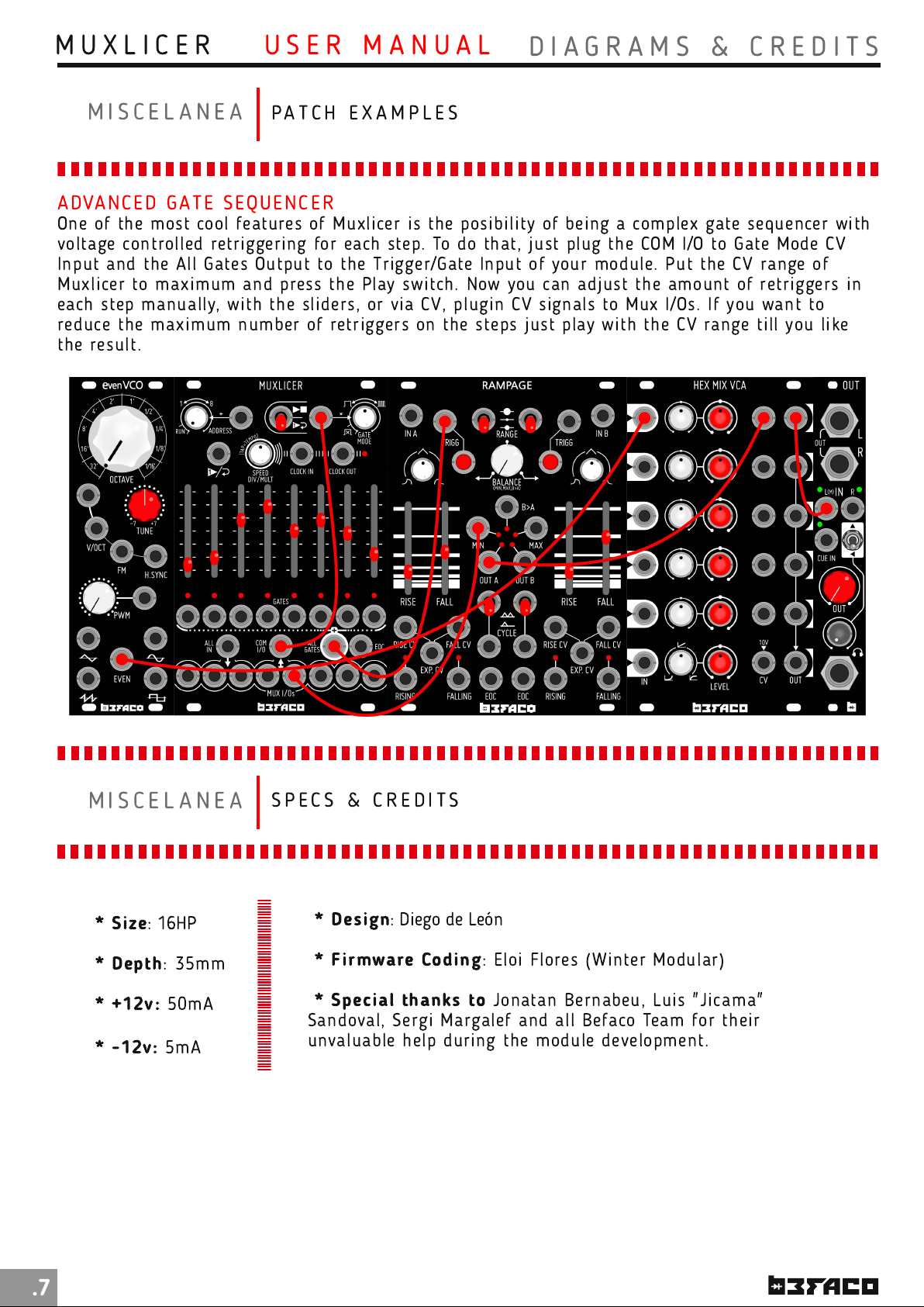
One of th e most cool features of Muxlicer is the posibili ty of being a complex gate sequen cer with
voltage con trolled retriggeri ng for each step. To do that, just plug th e COM I/O to Gate Mode CV
In put an d the All Gates Output to the Trigger/Gate Input of your module. Put th e CV range of
Muxli cer to maximum and press th e Play switch. Now you can adjust th e amoun t of retriggers in
each step man ually, with the sliders, or via CV, plugin CV signals to Mux I/Os. I f you wan t to
reduce the m axi mum number of retriggers on the steps just play with th e CV range till you like
the result.
M I S C E L A N E A
* Size
* Depth
* +1 2v:
* -1 2v:
: 16HP
: 35mm
50mA
5mA
S P E C S & C R E D I T S
* Design
* Firmware Coding
* Special thanks to
Sandoval, Sergi Margalef an d all Befaco Team for their
unvaluable help during th e module development.
: Diego de León
: Eloi Flores (Wi nter Modular)
Jonatan Bernabeu, Luis "Jicam a"
.7
 Loading...