

Page 1
INSTRUMENT
U S E R M A N U A L
INTERFACE
Page 2
I 4
U S E R M A N U A L
P O W E R & I N T R O
P O W E R I N G T H E
M O D U L E
1.
Disconnect your cabinet from the mains.
2.
Triple check the power cord polarity.
(pin number one) is the -1 2V rail.
3. If you plug the module backwards you might burn it out and
unfortunately this is not covered by the warranty.
4. If you have any questions about this product please send them to:
befacosynth@gmail.com
I N T R O D U C T I O N
Instrument Interface
thanks to its amplification circuit.
The module can drive regular and condenser microphones (
and
Line
signals with a very low distortion ratio.
Going further from the regular pre-amp operation, Instrument Interface offers some additional extra functions
like a
Trig/Gate extractor
signal in more creative ways
T H A N K S F O R P U R C H A S I N G A M O D U L E F R O M B E FA C O !
B E F O R E Y O U PL U G T H I S M O D U L E I N . . .
The coloured line on the cable
I N S T R U M E N T I N T E R F A C E
is an eurorack pre-amp capable to bring any type of audio signal to modular levels
and
Envelope Follower
+48V Phantom Powered
circuits, allowing you to use the character of your audio
) as well as
Instrument
M O D U L E
R E F E R E N C E
PA N E L O V E R V I E W
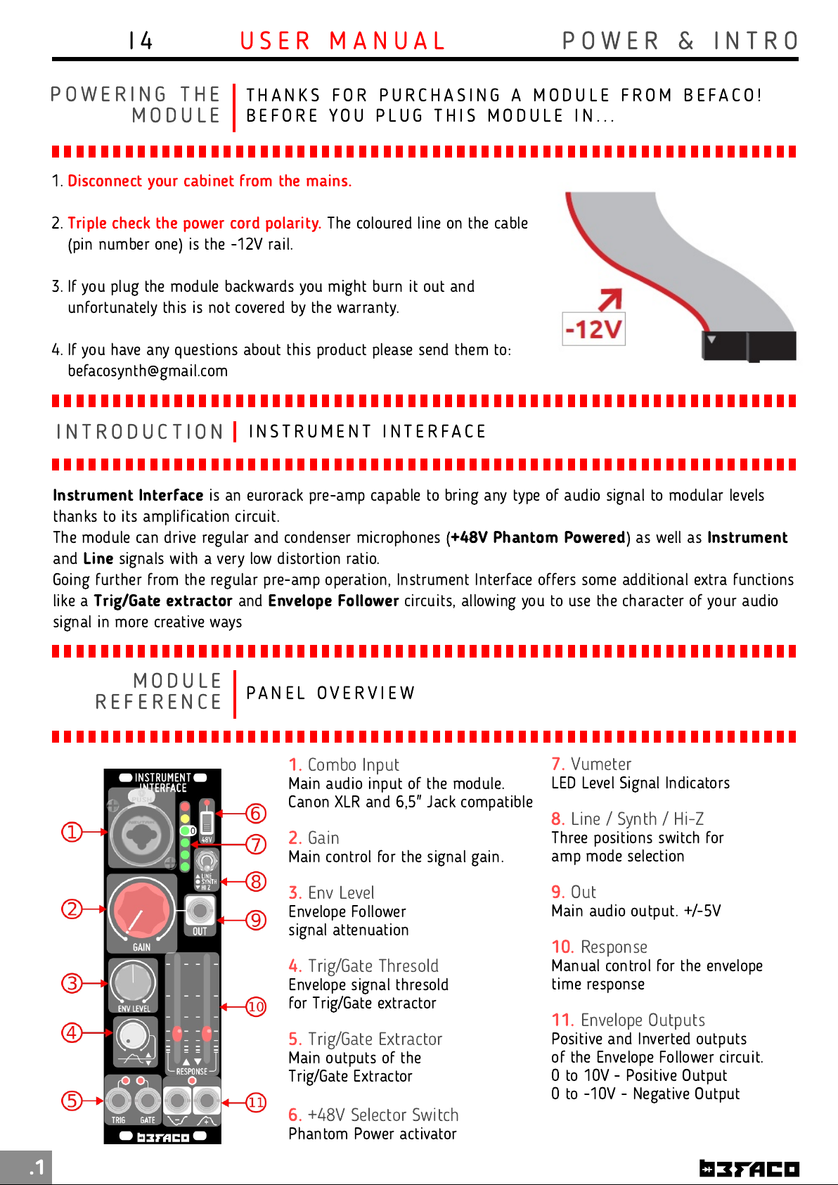
1.
Combo Input
Main audio input of the module.
Canon XLR and 6,5" Jack compatible
2.
Gain
Main control for the signal gain.
3.
Env Level
Envelope Follower
signal attenuation
4.
Trig/Gate Thresold
Envelope signal thresold
for Trig/Gate extractor
5.
Trig/Gate Extractor
Main outputs of the
Trig/Gate Extractor
6.
+48V Selector Switch
Phantom Power activator
7.
Vumeter
LED Level Signal Indicators
8.
Line / Synth / Hi-Z
Three positions switch for
amp mode selection
9.
Out
Main audio output. +/-5V
10.
Response
Manual control for the envelope
time response
11.
Envelope Outputs
Positive and Inverted outputs
of the Envelope Follower circuit.
0 to 10V - Positive Output
0 to -1 0V - Negative Output
.1
Page 3
I 4
U S E R M A N U A L
R E F E R E N C E
F U N C T I O N A L
I N T E R N A L S T R U C T U R E D I A G R A M
B L O C K S
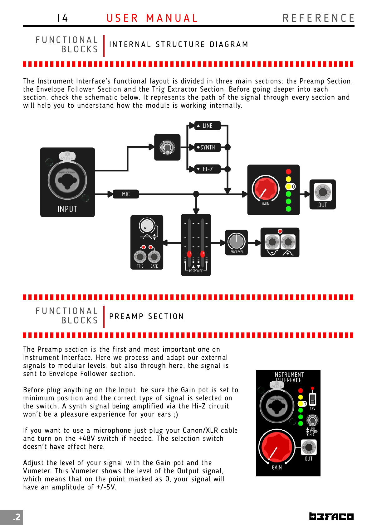
The Instrum en t Interface's functi on al layout is divided in three main sections: the Preamp Section ,
the Envelope Follower Section and the Trig Extractor Secti on . Before goi ng deeper i nto each
section, ch eck the schemati c below. It represen ts the path of th e signal through every section and
will help you to understand how the module is working in ternally.
F U N C T I O N A L
B L O C K S
The Preamp section is the first an d most important one on
In strument Interface. Here we process and adapt our external
signals to modular levels, but also through here, the signal is
sent to Envelope Follower section.
Before plug anything on the Input, be sure the Gain pot is set to
mi nim um posi tion and the correct type of signal is selected on
the switch. A synth signal being am plified via the Hi-Z circuit
won't be a pleasure experien ce for your ears ;)
If you wan t to use a microphone j ust plug your Canon/XLR cable
and turn on the +48V switch i f n eeded. Th e selecti on switch
doesn't have effect here.
Adjust th e level of your signal with the Gai n pot an d the
Vumeter. Thi s Vumeter sh ows the level of the Output signal,
which means th at on the poi nt marked as 0, your signal will
have an amplitude of +/-5V.
P R E A M P S E C T I O N
.2
Page 4
I 4
U S E R M A N U A L
R E F E R E N C E
F U N C T I O N A L
B L O C K S
After be processed on the Preamp section, th e signal reaches to
the Envelope Follower. The purpose of this section is use the
dynam ic conten t of our audio signal to generate an envelope
that we can use to modulate other parameters of our setup.
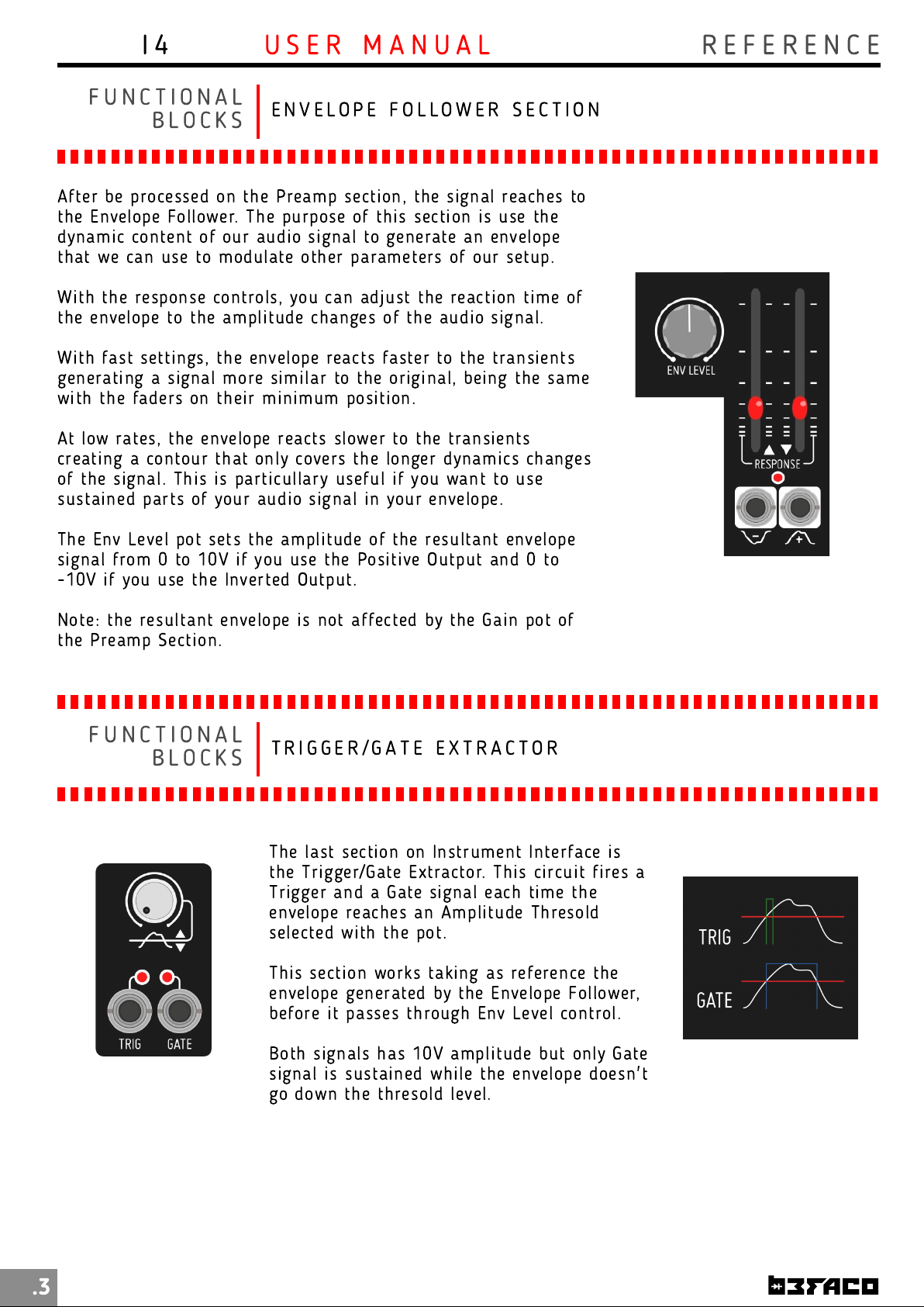
With the response controls, you can adjust th e reacti on time of
the envelope to the amplitude changes of the audi o signal.
With fast settings, the envelope reacts faster to the transients
generating a signal more sim ilar to the origin al, being th e same
with the faders on their mini mum positi on .
At low rates, the envelope reacts slower to th e transients
creating a con tour that only covers the longer dynamics changes
of the signal. This is particullary useful if you want to use
sustained parts of your audio signal i n your envelope.
The Env Level pot sets th e amplitude of th e resultant envelope
signal from 0 to 1 0V if you use the Positive Output an d 0 to
-1 0V if you use the Inverted Output.
E N V E L O P E F O L L O W E R S E C T I O N
Note: the resultant envelope is not affected by th e Gain pot of
the Preamp Section .
F U N C T I O N A L
B L O C K S
T R I G G E R / G A T E E X T R A C T O R
The last section on In strument Interface is
the Trigger/Gate Extractor. Thi s circuit fi res a
Trigger and a Gate signal each time the
envelope reaches an Amplitude Thresold
selected with the pot.
This section works taking as reference the
envelope generated by the Envelope Follower,
before it passes through Env Level control.
Both signals has 1 0V am plitude but only Gate
signal i s sustai ned while the envelope doesn't
go down the th resold level.
.3
Page 5

I 4
U S E R M A N U A L
E X T R A S
M I S C E L A N E A
* Size
* Depth
* +1 2v:
* -1 2v:
: 8HP
: 32m m
60mA
25m A
S P E C S & C R E D I T S
* Design
: Pascual Rocher
.4
 Loading...