

Page 1

BEEWORKS 05 STABILIZER
USER GUIDE
BeeWorks LLC
www.beeworksgear.com
Last Modified: November 11, 2015
Copyright © 2015 BeeWorks LLC. All rights reserved.
Page 2

Table of Contents
What’s in the Case? 3
Getting Started 4
Step 1: Assemble the BW05 5
Step 2: Balance the Camera 7
Step 3: Calibrate the Sensors 9
Step 4: Select Mode of Operation 10
Inverted Operation 11
Attaching a Monitor 12
Tune the Stabilizer 13
Assembling the Kinetic Remote 14
Using the Kinetic Remote 16
Support 18
Page of 2 18
Page 3
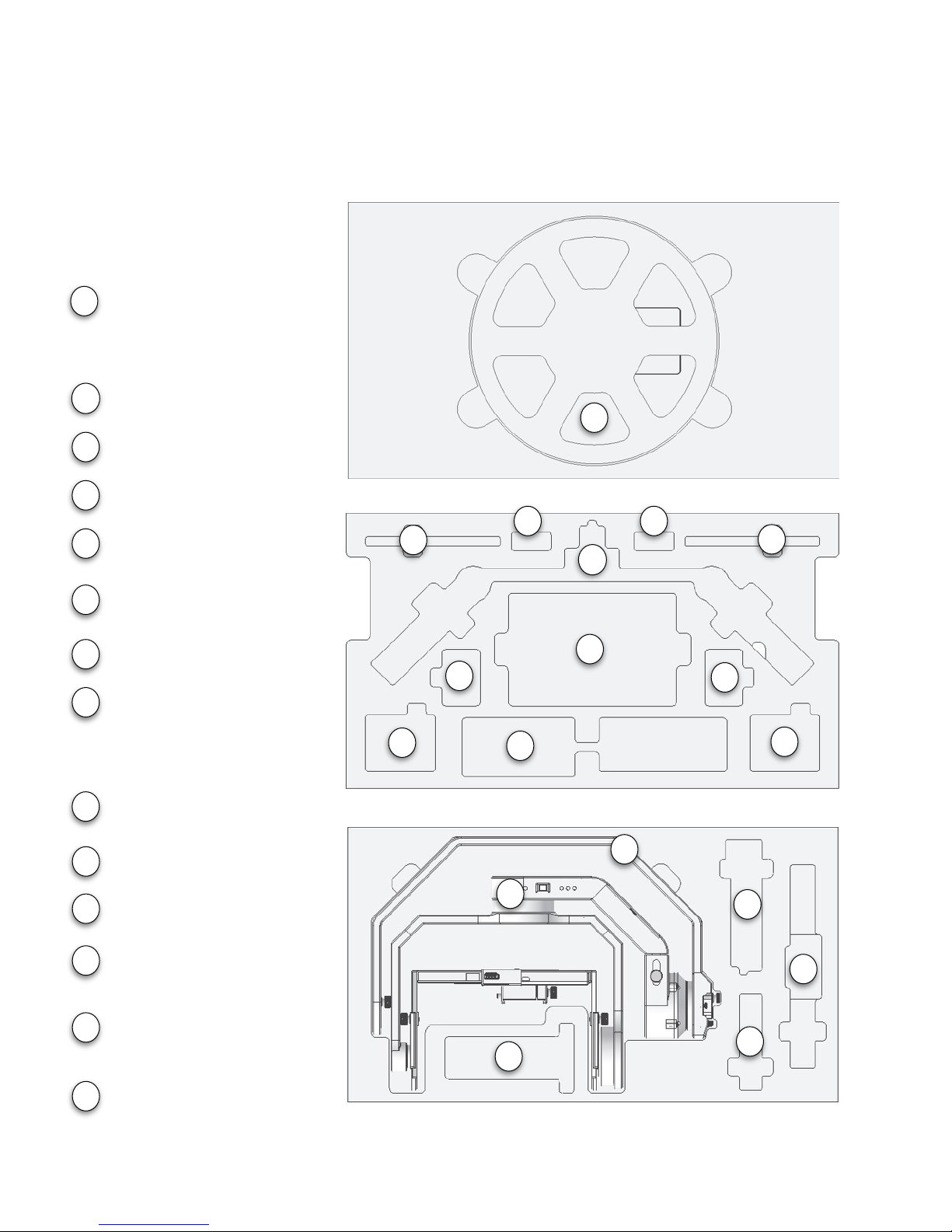
What’s in the Case?
"
Page of 3 18
12
2
4
3
3
7
8
8
6
6
5
5
9
2
3
4
5
6
7
8
Handlebar
BW05 Battery
Battery Charger
Thumb Screws
Kinetic Remote
Antenna (Optional)
Monitor (Optional)
Monitor Battery (Optional)
BW05 Stabilizer
Camera Plate
Stand Spine
Paralinx Receiver
(Optional)
Remote Antenna Case
(Optional)
Kinetic Remote
Controller (Optional)
Middle Layer
Bottom Layer
10
11
13
14
9
10
11
12
13
14
Stand Base
Case Lid
1
1
Page 4
Getting Started
To start shooting with the BW05 stabilizer, you will accomplish the following steps:
1.
Assemble the BW05
2.
Balance the camera
3.
Calibrate the sensors (recommended before each day of shooting)
4.
Choose the mode of operation"
Page of 4 18
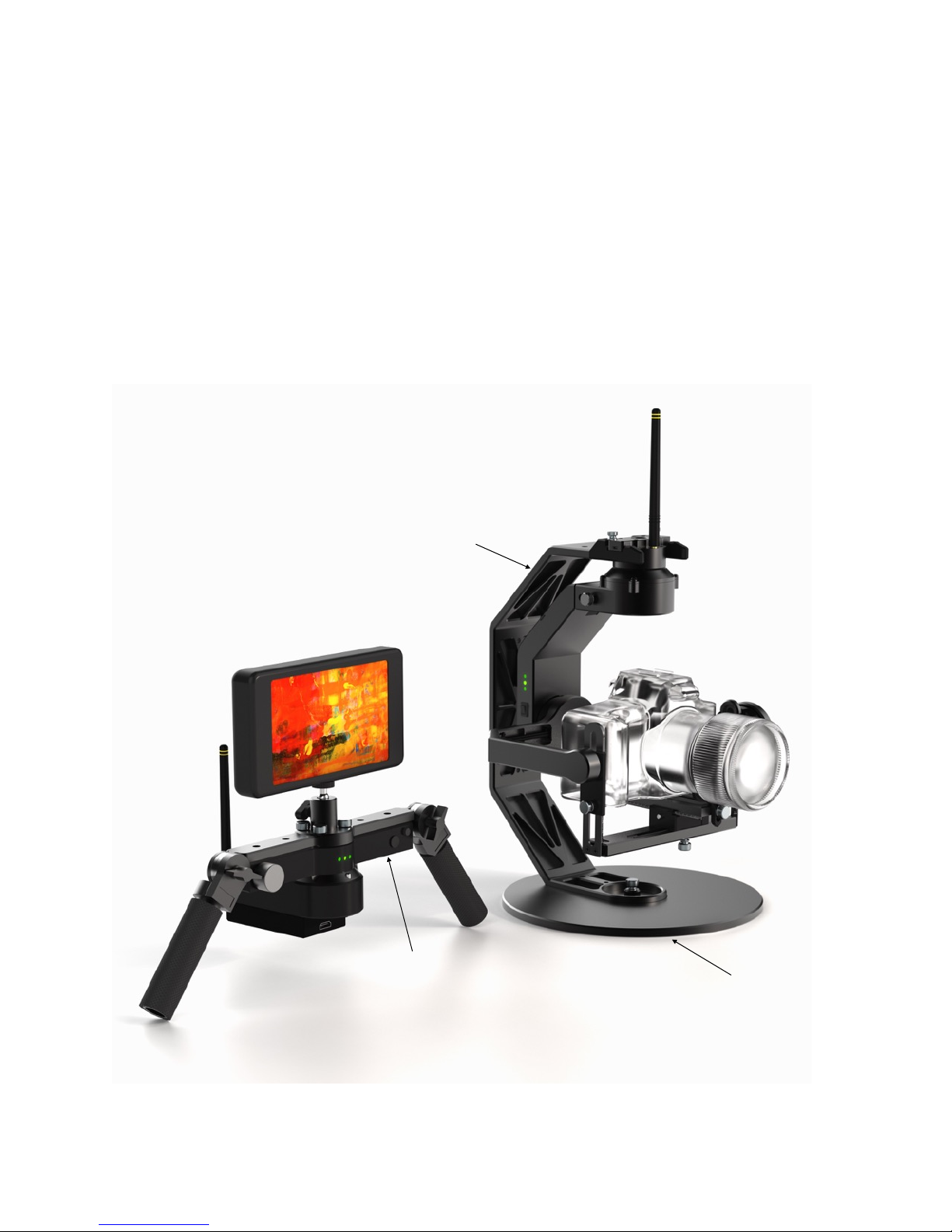
Stand Spine
Stand Base
Kinetic Remote
Controller
Page 5
Step 1: Assemble the BW05
1.
Watch the video (beeworksgear.com/support).
2.
Set the stand base on a firm surface.
3.
Attach the stand spine and stabilizer to the
stand base using your choice of one or two
thumb screws.
4.
Attach the camera plate to your camera.
Position the lens cradle to support the camera
lens without inhibiting its operation (focus,
zoom, etc.)
5.
Tighten the thumbscrew with a coin.
6.
Adjust the lens cradle to fit snugly against the
lens.
7.
Slide the camera plate onto the stabilizer and
tighten the thumbscrew.
8.
Connect the battery. Place it in the battery
compartment, and replace the battery door.
9.
Remove the two small thumb screws at the top
of the stabilizer and move them back to the
extra holes provided.
10.
Keeping the stabilizer on the stand, attach the handlebar. The handle adjustment knobs
should face the operator (opposite the lens direction).
11.
Fasten the handlebar using four (4) 1/4-20” thumbscrews.
Page of 5 18
Page 6

TIPS FOR ASSEMBLY
*
The case layout is designed so that gravity will pull the stabilizer into the correct position when
removed. When looking into the lens of the camera, the tilt (pitch) motor should be on the right
side. When putting the stabilizer in its case, rotate the tilt motor toward the panning motor. It is
likely that the camera height adjustments will need to be extended to fit properly in the case.
*
To prevent the stabilizer from detaching from the stand when removed from the case, we
recommend attaching the stabilizer to the stand with the small thumbscrews before putting it
back into the case.
*
There is a threaded hole available to use a second thumb screw between the stand and base.
This screw is designed to be an optional secondary mounting point for safety and stability
when mounting the stabilizer on moving objects. There are also additional 1/4-20 mounting
holes on the back and top of the stand spine, allowing you to mount it from multiple locations
in situations that require extra support (on moving vehicles, for example).
*
Two suction cups can be attached to the back of the spine to attach it to smooth vertical
surfaces, such as windows or vehicles. In this configuration, the stand base should be
removed.
*
Three suctions cups can be added to the bottom of the stand base to attach it to smoother
horizontal surfaces.
*
Take care to avoid twisting the cables that run through the stabilizer motors. If the cables
become twisted, simply rotate the axis in the opposite direction to untwist them. Twisted
cables can impact stabilizer performance.
Page of 6 18
Page 7
Step 2: Balance the Camera
1.
Watch the balancing video (www.beeworksgear.com/support)
2.
Place the stabilizer on the stand on a sturdy level surface.
3.
Ensure that the BW05 power is OFF.
4.
Adjust lens zoom (if applicable) to an appropriate level.
5.
Remove the lens cap.
6.
Ensure that all cables and accessories you intend to use are attached.
7.
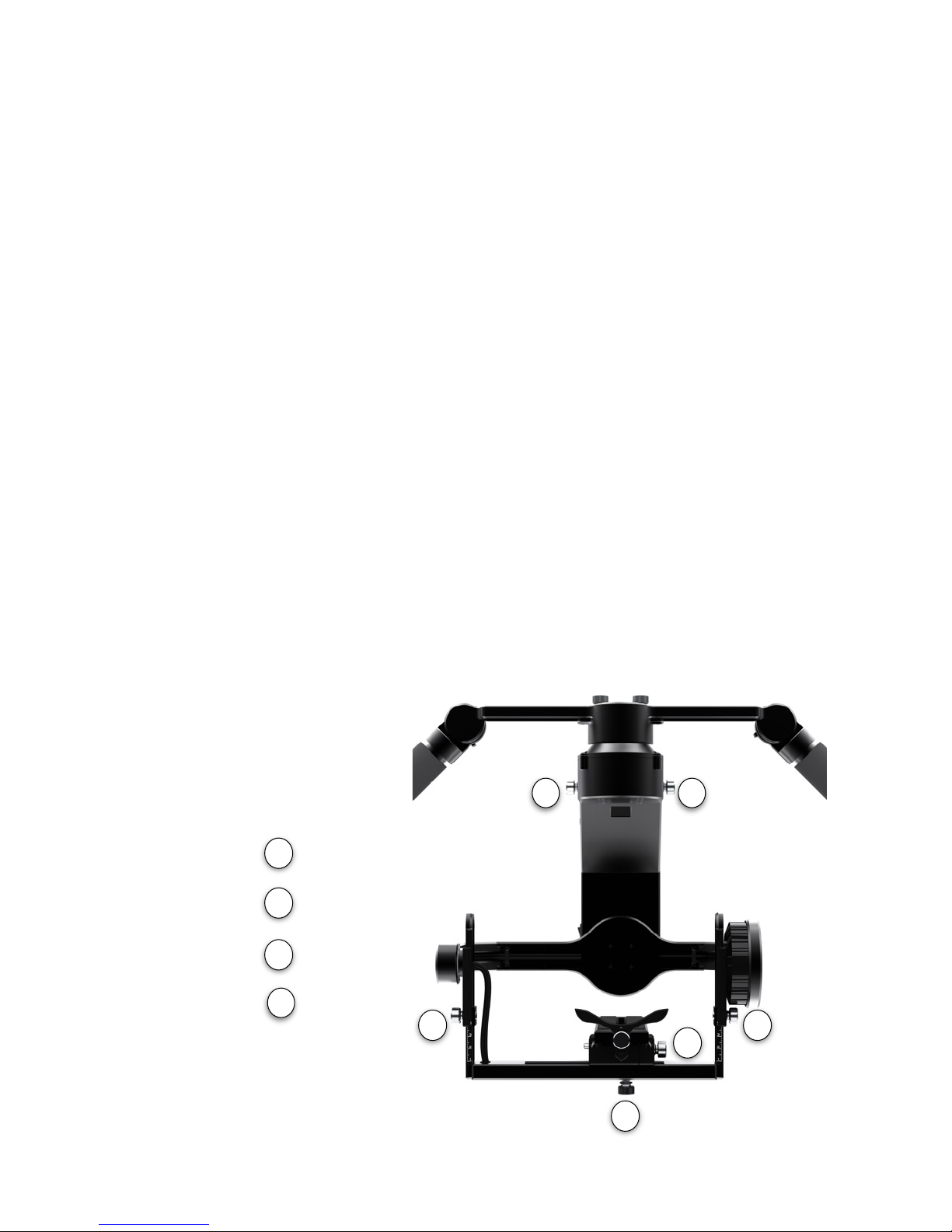
First, adjust the camera so that it sits upright and level. Move the camera plate forward or
backward to find a neutral position. Then tighten the thumb screw. (Step 7 label)
8.
Find the neutral roll position by moving the adjustment left or right. (Step 8 label).
9.
Point the lens 90 degrees up. Note whether it holds this position, drops forward (toward the
lens), or drops backward. Your goal is to have it hold position. If it falls forward, raise the
camera platform by adjusting the thumb screws (Step 9 label) on either side. If it falls
backward, lower the camera platform. Check that the left and right adjustment points are set
to the same value.
10.
Point the lens 90 degrees down and verify that it holds position. The behavior should be the
same as the 90-degree up position.
Page of 7 18
Up/Down
Left/Right
Forward/Back
Panning
7
8
9
121212
9
9
8
7
Page 8

11.
After adjusting the up/down balance, you may need to readjust the forward/back balance
from your initial balance point.
12.
When the camera is able to rest in any position and has symmetrical behavior, check the
balance of the entire system. Set the camera in the neutral position and then tilt the
stabilizer sideways by 45 degrees. The stabilizer should not “fall” to one side around the
panning axis when tilted. If it does, adjust the telescoping section behind the pan motor at
the top of the stabilizer (Step 12 label above). For lighter camera/lens combinations, this
adjustment will remain all the way in (the most compact position). For heavier camera / lens
combinations, it may need to be adjusted out.
An ideally balanced stabilizer should hold any camera position with the stabilizer
motors turned off. In other words, it should not “fall” in one direction over the
other direction. If you roll and tilt the camera, it should rest in the position that
you put it. If you return the camera to center, it should rest in that position, as
well. Often, it is not possible to achieve a perfect balance because of the geometry
of the camera. In this case, strive for symmetry. For example, if you roll the
camera to the left, it should behave the same way as when you roll the camera to
the right.
TIPS FOR BALANCING THE CAMERA
*
Once you balance a camera the first time, the common adjustments are the front-to-back
camera plate adjustment and the camera platform height adjustment. These adjustments
need to be made after each assembly out of the case or when changing lenses. The other
adjustments rarely need to change unless you are changing cameras.
*
Double check that all thumbscrews are tight before operating. If an adjustment slips, it will
affect the balance and performance of the system.
*
Adding or removing the lens cap, or changing cables will affect balance. If you make changes
to the camera setup, make the necessary adjustments to the balance.
*
Take care to ensure that any installed cables do not impinge the movement of the stabilizer.
*
Good balance is critical to good stabilizer and Kinetic Remote performance. Check the
balance each time you use the stabilizer. With practice, common balance adjustments should
take only a couple minutes.
*
Heavier cameras require more precise balance than lighter cameras for good stabilizer
performance. If you have a large camera / lens combination, you should allow more time to
balance the system more precisely.
Page of 8 18
Page 9

Step 3: Calibrate the Sensors
When you turn on the stabilizer, it should balance the camera in an upright position with the
horizon level. To ensure a proper alignment, the sensors in the system need to be calibrated
occasionally, particularly after changes in temperature or if you travel with the system. It is good
practice to calibrate the sensors before each day of shooting, as the process takes only 10
seconds.
1.
Set the stabilizer on the stand on a sturdy level surface.
2.
Attach and balance your camera.
3.
Turn on the stabilizer and wait for the start-up sequence to complete (three green lights
flash).
4.
Hold the stabilizer mode button down for two seconds.
5.
The lights will blink red, and the motors will turn off to indicate “calibration” mode.
6.
Gently tap the stabilizer button once to start the calibration sequence.
7.
The stabilizer will wait one second for the button shake to dissipate and will then calibrate
the sensors. It takes about 10 seconds. Do not bump or move the stabilizer during
calibration.
8.
When the calibration is complete, the lights will flash green, the motors will turn on, and the
stabilizer will return to normal operation.
TIPS FOR SENSOR CALIBRATION
*
Calibration is not necessary every time you turn on the stabilizer. However, variables like air
pressure changes, temperature changes, and long periods of time can cause the calibration to
drift slightly. For best performance, we recommend calibrating each time you set up the
stabilizer at a new shooting location.
*
It is possible to temporarily change the horizon point by turning follow mode off (three red
lights) when the camera is not in a neutral position. You can use this to your advantage, for
example, if you want to mount the camera when it is tilting up. To reset the neutral position in
this case, simply turn off the stabilizer and then turn it on again.
Page of 9 18
Page 10
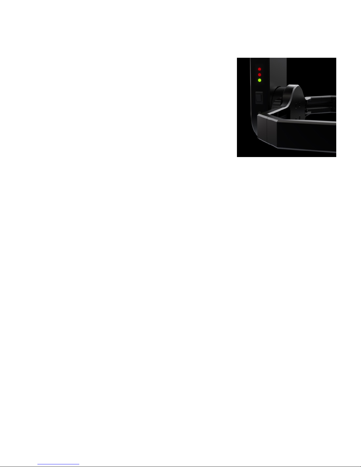
Step 4: Select Mode of Operation
The BeeWorks 5 Stabilizer has four main modes of operations in
addition to the configuration mode described above. Change
modes by pressing the mode button on the side of the BW05.
The four primary modes of normal operation are:
•
Pan Follow (One Green Light) - The stabilizer will follow
movements of the handlebar in panning.
•
Pan/Tilt Follow (Two Green Lights) - The stabilizer will follow
movements in panning and tilting.
•
Pan/Tilt/Roll Follow (Three Green Lights) - The stabilizer will
follow movements in all three axes.
•
Follow Off (Three Dim Red Lights) - The stabilizer will hold the camera in a fixed position
regardless of handlebar movement. "
Page of 10 18
Page 11
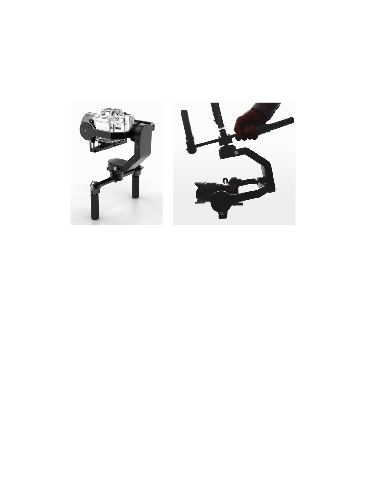
Inverted Operation
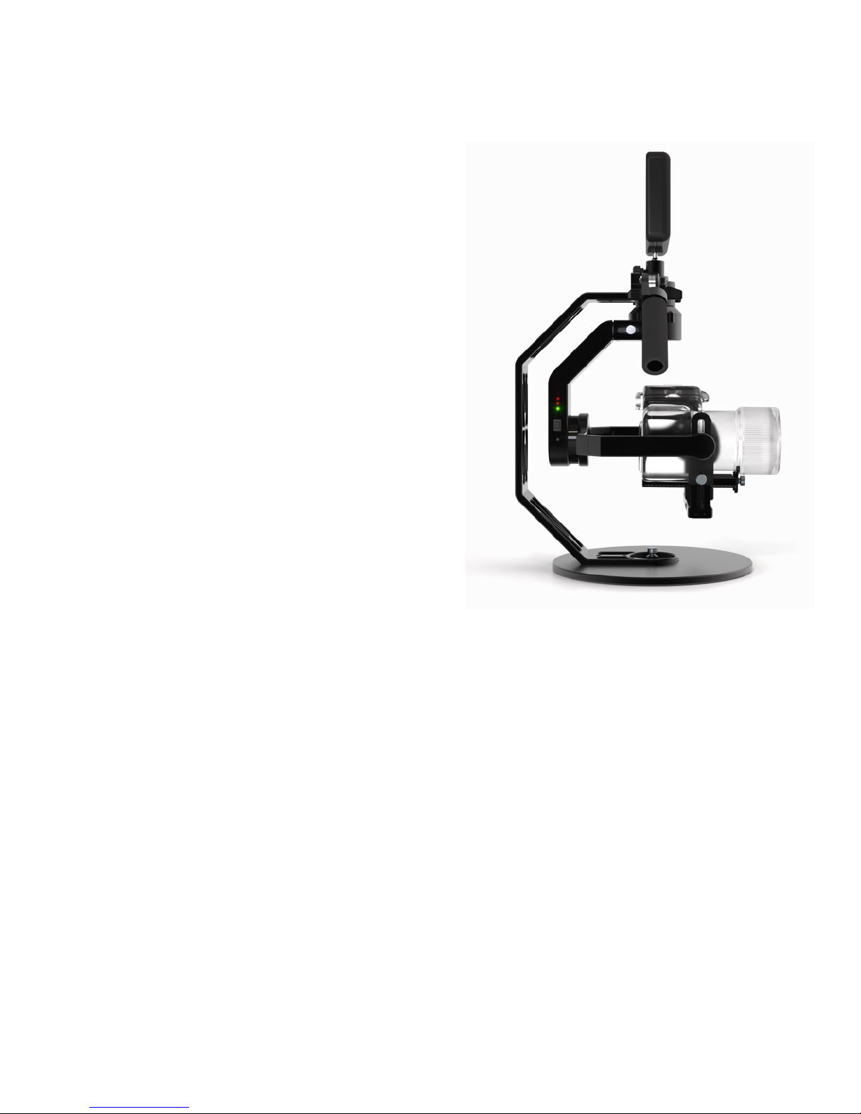
In addition to the modes described above, the BW05 can be operating in various configurations,
such as inverted. Simply turn off the stabilizer and turn it upside down. Rotate the tilt motor past
the pan motor and rebalance the camera left/right, if necessary. Turn on the stabilizer, and it will
automatically sense the new orientation. Similarly, you can operate the BW05 in a number of
other configurations that you may find useful for different shots. Take advantage of the
adjustable handles to determine what positions work best for you. Note that you can rotate the
camera to a position of your choice it Pan Follow mode. For example, the underslung position in
the image above can have the camera pointed forward or to the side.
Page of 11 18
Page 12
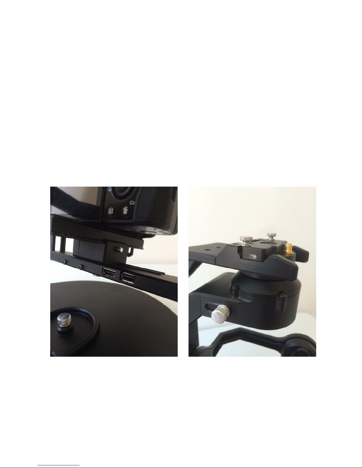
Attaching a Monitor
An internal HDMI cable is routed through the stabilizer to connect the camera to the monitor,
which minimizes cable interference with stabilizer movement. To complete your monitor
setup, you need two short HDMI cables that are compatible with the HDMI ports on the
BW05 and on your camera and monitor.
To attach your monitor:
1.
Attach the monitor to the mini ball head mount on the handlebar.
2.
Connect a short cable between your camera and the standard HDMI-A port under the
camera plate.
3.
Connect the other short cable between your monitor and the micro HDMI-D port under the
handlebar.
Page of 12 18
Page 13

Tune the Stabilizer
If the stabilizer is buzzing or vibrating, the most likely cause is incorrect balance. In the event
the camera is balanced properly, you may need to tune the stabilizer. There are two ways to
tune. One option is to use the auto-tune function described below. Auto-tune does not work
reliably for all camera/lens combinations. The other option is to tune manually with the
configuration software available on the BeeWorks Support page
Electronic stabilizers use a complex array of settings to stabilize the camera. If these settings
are not correct, it can result in vibrations, noise, or a stabilizer that feels weak. Fortunately, the
BeeWorks 5 can use its sensors and internal computer to optimize these settings for you.
1.
Set the stabilizer on the stand and place it on a firm, level surface.
2.
Attach and balance your camera.
3.
Turn on the stabilizer and wait for the start-up sequence to complete.
4.
Hold the stabilizer Mode button down for two seconds.
5.
The lights will blink red, and the motors will turn off to indicate “calibration” mode.
6.
Place the camera in the neutral position. Tilt and roll should be level. The pan position
should be in line with the stand spine.
7.
Gently double-tap the stabilizer button (two clicks in succession) to start the auto-tune
sequence.
8.
The stabilizer will wait a second for the button shake to dissipate and will then auto-tune the
sensors. The stabilizer will make a series of sounds while it is testing different settings. It
may also shake or vibrate at times. This is normal behavior.
9.
Auto-tuning typically takes about 10 minutes.
10.
When the calibration is complete, the lights will flash green, the motors will turn on, and the
stabilizer will return to normal operation. The motors should be silent and smooth through
the operational range of camera positions.
Page of 13 18
Page 14
TIPS FOR AUTO-TUNING
* The camera must be well balance before auto-tuning.
*
The auto-tune settings will be saved to the stabilizer and will be preserved when you turn it off.
*
If you feel a buzzing or vibration in the handlebars while using the stabilizer, this vibration may
also be apparent in your footage. If this is the case, check you camera balance. If proper
balance does not resolve the issue, then auto-tuning may be required.
*
On rare occasions, the vibrations that occur during auto-tuning can sometimes loosen the
adjustment screws. Double check that the thumb screws and camera plate screw are firmly
tightened after auto-tuning.
*
For best performance, we recommend auto-tuning with a fresh battery and then replacing or
recharging that battery before returning to normal operation.
*
Because of the time and stable environment that auto-tuning requires, we recommend
performing the auto-tune in advance before arriving at a busy filming location. Contrast this
advice with the 10-second sensor calibration, which should be done on location.
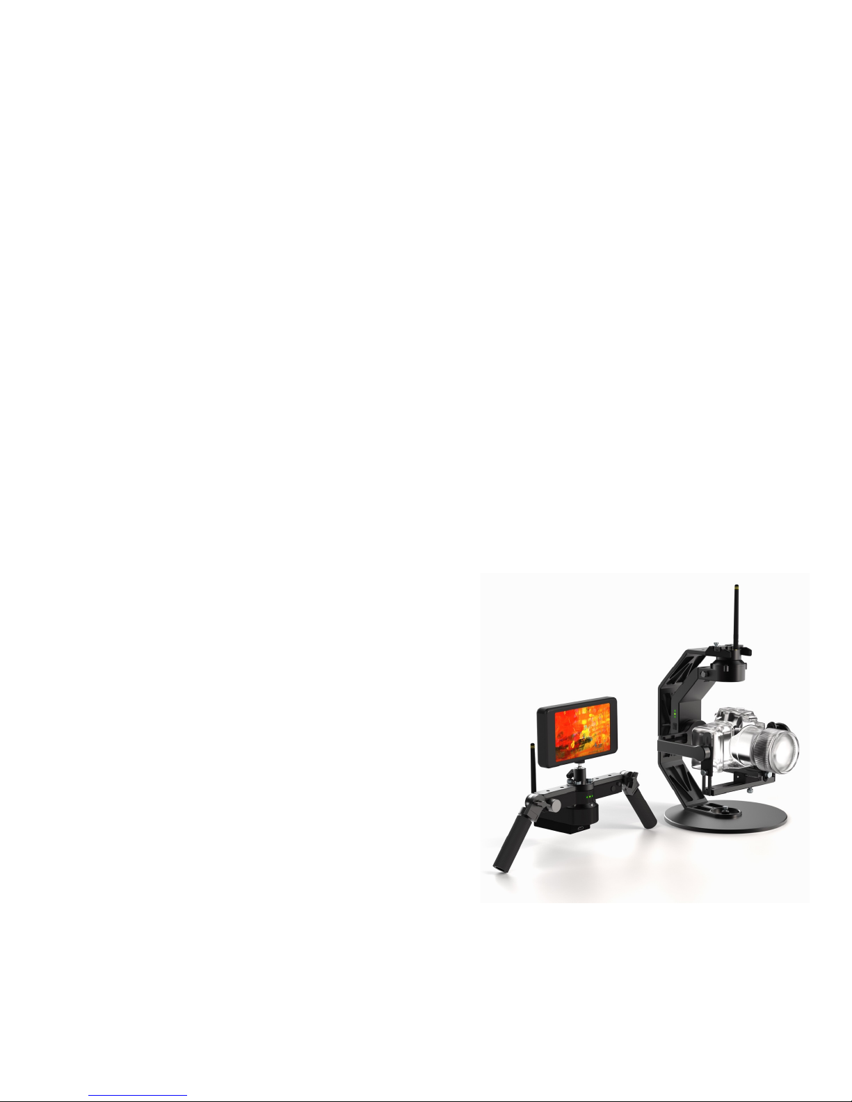
Assembling the Kinetic Remote
1.
Watch the video (beeworksgear.com/support)
2.
Remove the handlebar.
3.
Attach the stabilizer to the stand using the two (2)
6-32 thumbscrews provided.
4.
Attach the Kinetic Remote Controller to the
handlebar using four (4) 1/4-20 thumbscrews.
5.
If you are attaching the Paralinx Arrow receiver,
use a camera plate screw to attach it prior to
inserting the battery into the battery compartment.
6.
Insert a fresh battery into the battery
compartment and slide on the battery cover.
7.
Attach the Remote Antenna Case to the
Controller unit. The Remote Antenna Case slides
in from the back and clicks into place. When
reversing this operation, press the pin to
disconnect the two units.
8.
Attach your monitor to the handlebar mini ball head mount.
Page of 14 18
Page 15

9.
Connect the monitor to your wireless video receiver.
10.
Connect the Antenna Box to the Handlebar Unit using an USB 3.0 cable.
11.
Attach the provided antennas to the Antenna Box and the Stabilizer.
TIPS FOR ASSEMBLING THE KINETIC REMOTE
*
The Kinetic Remote antennas are most effective when they are parallel to each other (for
example, both pointing up). They are least effective when the tips of the antennas are pointing
directly at each other.
*
The Remote Antenna Case and Kinetic Remote Controller Unit are detachable, because
certain situations require careful antenna placement. For example, you may want to control
the stabilizer from inside a vehicle but have the antenna placed on the outside of the vehicle.
You can maximize the antenna range of the BeeWorks control system and the Paralinx
wireless video system by keeping antennas aligned. In this case, detach the Antenna Case
from the Handlebar Unit and use the standard 1/4-20 threaded screw hole to mount it to a
tripod or suction cup (it will mount upside down from the position used when attached to the
Handlebar Unit to put the Paralinx receiver on top)."
Page of 15 18
Page 16

Using the Kinetic Remote
After all of the cable attachments are made, turn on both the BeeWorks 5 stabilizer and Kinetic
Remote. The BW05 stabilizer will power the Paralinx Arrow transmitter, and the Kinetic Remote
will power the Paralinx Arrow receiver.
KINETIC REMOTE
To control the camera via the Kinetic Remote, press and hold the button on the remote and
move the remote unit. The lights on both devices should show the same green networking
animation to let you know that the position changes are being sent, and the camera will match
your moves.
When you take your finger off the button, the stabilizer will come to a stop in the current
position. The next time you press the button, the movement will start again where the last
movement ended.
If you want to lock the roll axis, simply double click and hold the Kinetic Remote button. The
double click will lock roll to the horizon and only allow you to control pan and tilt.
THUMB JOYSTICK
In certain situations, such as operating in tight spaces, a joystick may be better than the Kinetic
Remote. The joystick also is useful when you want a pure pan or tilt along a single axis.
The thumb joystick is simple to operate. Push it in the direction you want the camera to move
with your thumb. If there is any current roll applied, the camera will slowly come back to a level
horizon when you begin using the joystick. The dynamics of the joystick are controlled by the
Physics Engine (see below).
TIPS:
*
If you used the Kinetic Remote to put the camera in a roll position and you would like to level
it, tap the joystick. The camera will return to a level roll position.
*
You can quickly switch between Kinetic Remote and joystick usage in the same shot.
PHYSICS ENGINE
There is an advanced physics engine built in to the Kinetic Remote that processes your
movements to make them more cinematic and less robotic. It creates natural acceleration when
you begin a Kinetic Remote or joystick move, and it brings the camera to a stop naturally when
a movement ends. It also will slow down and stop the camera safely and organically when it
reaches the position limits of the stabilizer.
Page of 16 18
Page 17

To control the physics engine, you can adjust the silver knob on the Kinetic Remote. Rotate it
counter-clockwise to add virtual “mass” to the camera, making movements slower and
smoother. When it is twisted to the right, it makes the camera movements faster and more
responsive. The speed can be adjusted in real-time. For example, if you are panning with the
joystick using your right thumb, you can change the speed in real-time by changing the knob
with your left thumb.
Page of 17 18
Page 18

Support
If you have questions or need service on your stabilizer, please contact us.
Website: www.beeworksgear.com/support
Email: [email protected]
Phone: +1.206.588.6895
Page of 18 18
 Loading...