

Page 1
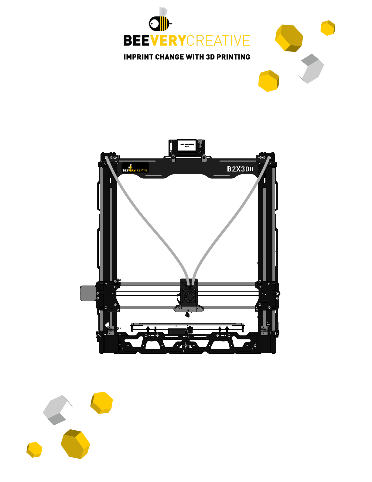
ASSEMBLY MANUAL
DIY 3D PRINTER KIT
B2X300
Page 2

VERSION
DATE DESCRIPTION PART NUMBERS
V1.20180503 03th May 2018
Beta-tester version
1212200001 to 1212200008
V2.20181107 7
th
November 2018
First release version
1212300001 to ------------
VERSIONS
Page 3

1
NEEDED TOOLS
Before you start to build your B2X300 3D printer, check if you have the necessary tools
to do it. You will need the following:
You will need a set of hex key for
the assembly.
There is a 1.5mm hex key
supplied with the kit.
Sometimes you might need to use
some extra strengh assembling
the printer.
You will need it towards the end. Always a helpful tool.
You will also need to remove
some strands from the
printed vparts with a cutter.
Take great care not to cut
yourself when doing this.
There is a Double Ring Spanner
included in the Structure Frame,
which can make the screw task
easier and quicker.
SET OF HEX KEYS SOFT FACE HAMMER
FLATHEAD SCREWDRIVER REGULAR PLIERS
BOX CUTTER
DOUBLE RING SPANNER
There is also a nozzle changing
tool in the Structure Frame, wich
will be usefull on a future
changing nozzle process.
NOZZLE CHANGER
You need a marker to write on the
labels, for better guidance
while building B2X300.
MARKER
Page 4
2
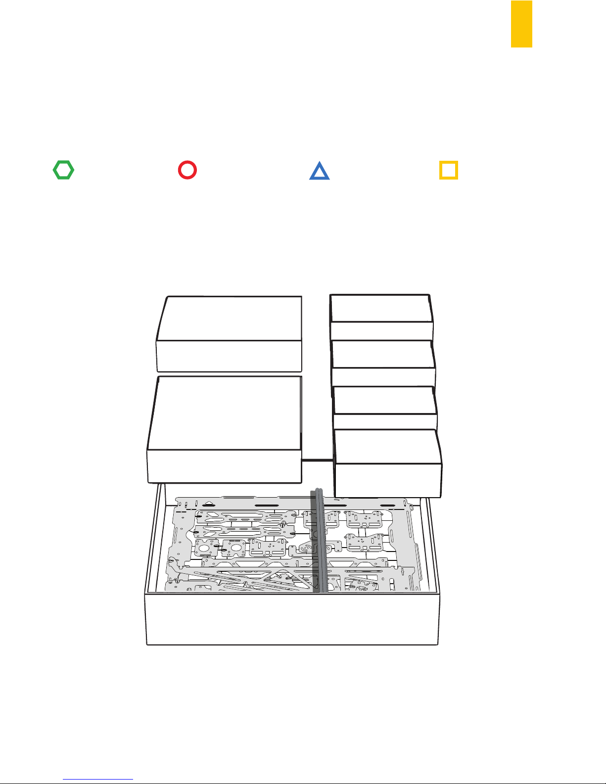
WHAT COMES WITH THE PACKAGE
BOX 3
BOX 0
Main Metal Frame
of your B2X300, guides
and Threaded Rods.
BOX 2
BOX 0
BOX 2
BOX 1
BOX 4
BOX 5
BOX 6
BOX 1
All the motors needed
are inside this box.
BOX 2
Inside this box you have
the glass, heated bed
and its cabling, and
the Printed Parts too.
BOX 4
Behold the Motherboard, the
Display and some of the
Electronic components.
BOX 5
The Extruder and
Auto-Calibration
Module is in this box.
BOX 3
Mechanic Parts
you need are right here.
BOX 6
In this box you have the
Power Supply.
To make recognizing each type of component easier, we’ve assigned a shape and colour to each type.
This way, we tried to divide all the components in boxes, just to make it easy for you.
STRUCTURE
MECHANICS
ELECTRONICS
PRINTED PARTS
Page 5
3
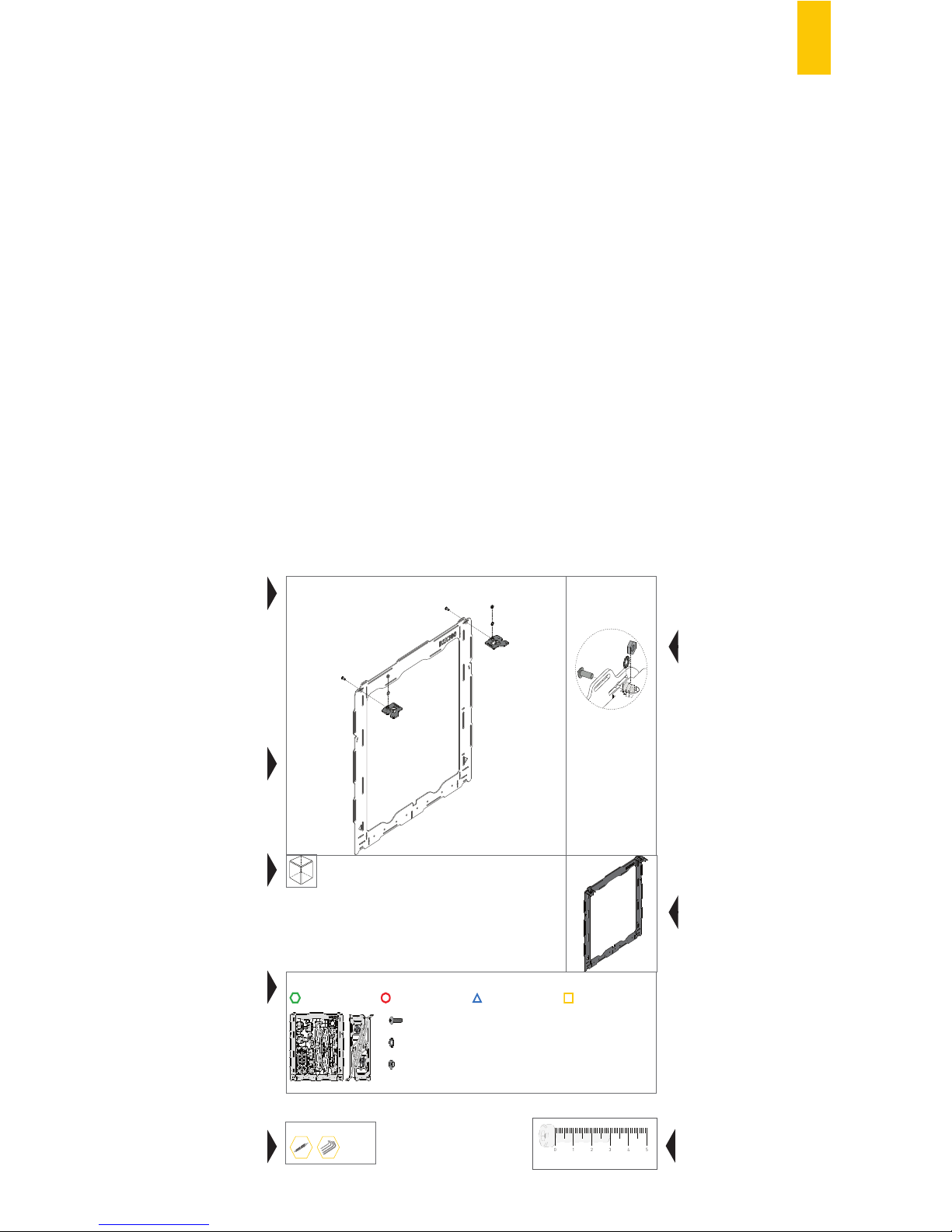
HOW TO READ THIS MANUAL
We have divided the manual into 6 chapters, from A to F, with each chapter describing
a part of the assembly process. Within each one, we’ve numbered every step.
This way, we will have the following chapters:
A – Assembling the structure.......................................................................................p.7
B – Assembling the build plate structure.....................................................................p.19
C – Assembling the X-Axis............................................................................................p.25
D – Assembling the X-Axis to the structure.................................................................p.33
E – Assembling the Extruder........................................................................................p.40
F – Assembling the Electronics....................................................................................p.51
We aim to make it simple for you, so we have created areas in this manual to help you
build your B2X300 3D printer as well and as easily as you can.
A.2
FRONT
RULER
01234
5
TOOLS
BUTTON HEAD SCREW DIN7380 M4X10
2
2
2
SERRATED LOCK WASHER DIN6798J M4
HEX. THIN NUT 1 DIN439 M4
STRUCTURE
MECHANICS
ELECTRONICS
PRINTED PARTS
This area will tell you
how to build each step
This letter and number
will help to guide your
building process.
There is a letter for each
set of steps of the assembly,
and a number for each step.
This area will tell you
from wich perspective
you are building
Which kit materials you
will use for each step
Here you will know
what tools you might
need to use
Space for some tips
and detailed instructions
What your assembly
should look like
after each step.
This ruler helps you
to measure the screws
and other mechanincs parts
01234
5
Page 6

4
TECHNICAL SPECIFICATIONS
LAYER RESOLUTION (user defined)
3D PRINTING TECHNOLOGY
PRINTING MATERIAL
MAX. BUILD VOLUME (up to)
HEATED BUILD PLATE
HEATED BUILD PLATE TEMPERATURE
DUAL EXTRUDER
NOZZLE DIAMETER
EXTRUDER MAX TEMPERATURE
TRINAMIC TMC 2130 DRIVERS
FILAMENT END DETECTION
MODULAR MOTHERBOARD
SENSORLESS HOMING
POWER LOSS DETECTION AND RECOVERY
EASY OFFSET CALIBRATION
STRUCTURE MATERIALS
PRINTER SIZE
WEIGHT
AMBIENT OPERATING TEMPERATURE
STORAGE TEMPERATURE
AC INPUT
POWER CONSUMPTION
CONNECTIVITY
INCLUDED ACCESSORIES
SUPPORTED FILE TYPES
AUTO BED LEVELLING
FIRMWARE
ELECTRONICS
RECOMMENDED 3D PRINTING/ SLICING SOFTWARE
SPEED
ASSEMBLY EXPERIENCE
50 - 300 microns
FFF
PLA, ABS, PETG, NYLON, Wood Composits, Metal Composits, HIPLA,
ABS-PC, HIPS, Carbon Composits
300 x 200 x 300 mm (11.81 x 7.87 x 11.81 in)
Yes (with 4mm removable glass surface)
50ºC (122ºF) – 130ºC (266ºF)
Yes, with two nozzle dual extruder
0.4mm | 0.4mm (other nozzle diameters available)
300ºC (572ºF)
Print more silently, especially on stealth mode. Faster printing speeds
with reduced vibrations and improved motion precision, without compromising print quality. Up to 256 microsteps.
Ability to detect absence of filament
Allows for future upgrades and customization
No limit switches required, thanks to the trinamic drivers
Possibility to resume printing after a power loss
Simple one step method, does not require mutiple test prints
High-quality powder-coated steel frame, Steel guides Removable glass
build plate,Full metal dual extruder
56 x 37.5 x 60 cm (22,04 x 14,76 x 23,62 in)
12kg (26,45 lb)
10-30ºC (50-86ºF)
5-35ºC (41º -95º F)
110-240VAC | 50-60Hz
360 W
SD Card | USB
Power cable | USB cable | Grease
.gcode
Auto Bed Levelling using a 15 point mesh, interpolated to 45 virtual
points
Marlin based
MKS Gen
Cura | Slic3r | Simplify 3D
up to 200 mm/s
+/- 6 hours
Page 7
5
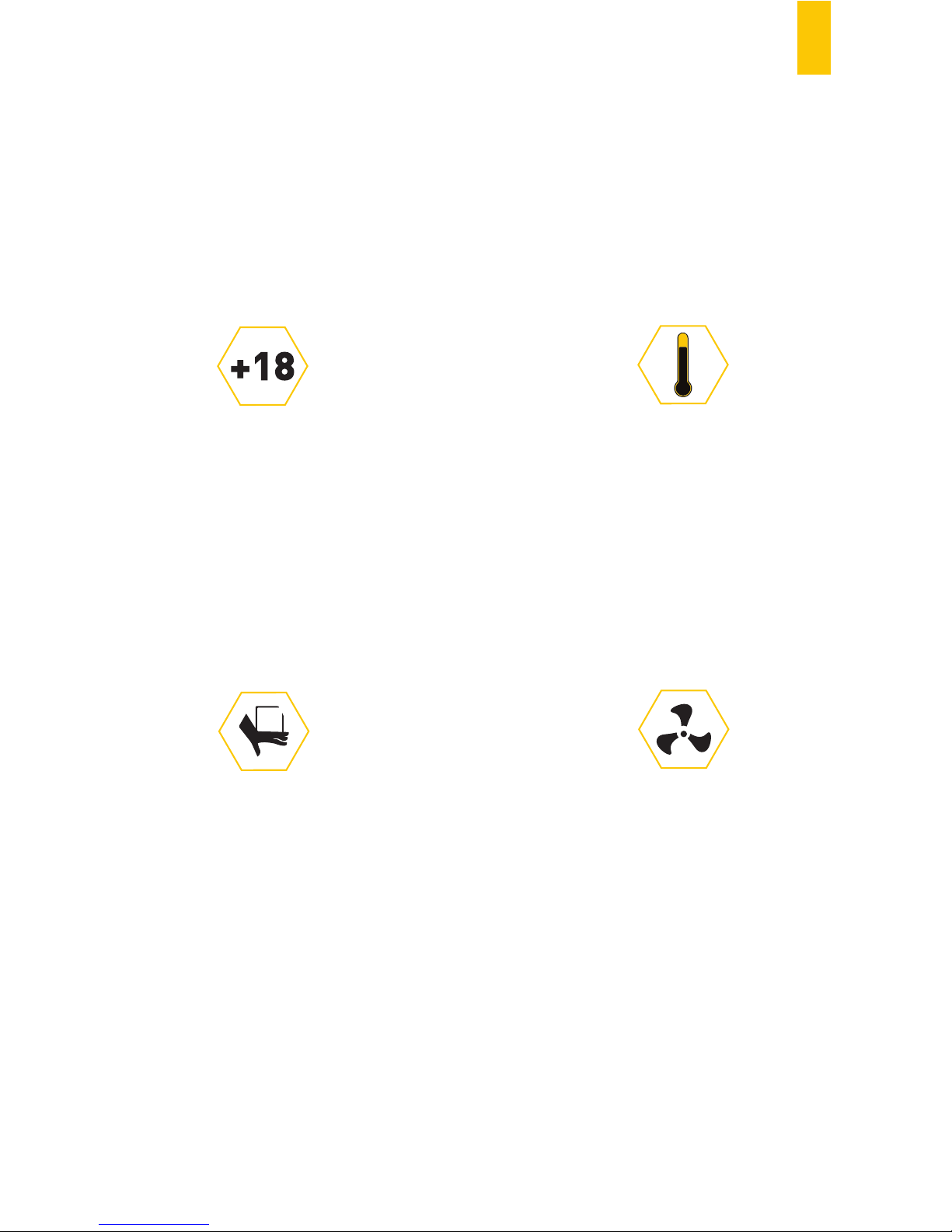
SAFETY INFORMATION
ADULT SUPERVISION
HIGH TEMPERATURES
COOL AND WELL-VENTILATED
ENVIRONMENT
MOVING PARTS
Other information you need to know
After assembling your B2X300, don’t drop/knock/damage it and don’t connect it to
zvvanything that hasn’t been previously validated by BEEVERYCREATIVE.
Make sure gases, explosive and other flammable materials aren’t kept, stored or
transported with your B2X300 3D printer or its parts.
Because we can’t stress this enough,
this 3D printer was developed to be used by adults.
Should you wish that children also use it,
you must supervise them at
all times while they do so.
You must also take great care with
small printed objects,
because children might try to swallow them,
which poses a danger of them choking.
Whenever this 3D printer is functioning,
some mechanical parts can
reach high temperatures,
which can cause serious burns if touched.
For that reason you must always
be careful not to touch it.
For better results with your 3D printer,
it is recommended you maintain an
acceptable level of air quality around the printer.
Environments with some ventilation are also
recommended so as to renew the air if you choose
to print with materials that release odors.
Whenever it’s functioning, this 3D printer
has moving parts.
For that reason, you should always
keep a safe distance
from the printer while it’s operating.
Even though the B2X300 3D printer was designed to be as safe as possible, we would
like to remind you it was conceived to be used by adults.
Still, there are safety concerns you must keep in mind:
Page 8

6
WARRANTY INFORMATION
B2X300 is a DIY 3D printer assembled by the user.
Its warranty is assured for the components that are included with the KIT.
Six month warranty guaranties the replacement of defective manufactured parts.
BEEVERYCREATIVE may request the return of this part in order to improve future developments.
Warranty will be voided if:
- inappropriate handling during assembly takes place.
- the user makes incorrect connections, breaks or damages parts during assembly.
Before assembling your B2X300 you must read thoroughly the Terms and Conditions of
the BEEVERYCREATIVE Standard Warranty on our website:
www.beeverycreative.com
Page 9

7
A
ASSEMBLING THE STRUCTURE
Page 10
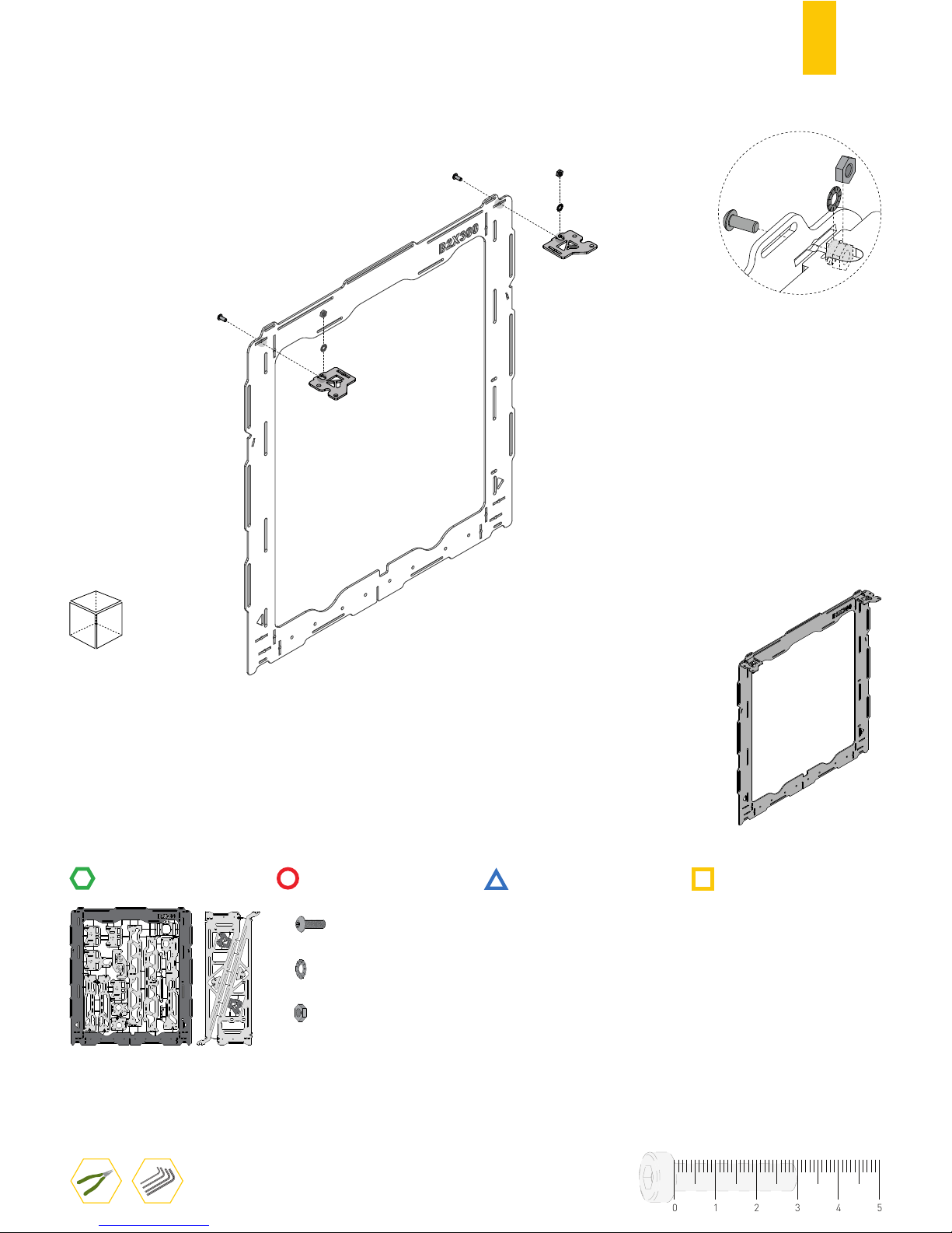
8
A.1
FRONT
RULER
TOOLS
BUTTON HEAD SCREW DIN7380 M4X10
2
2
2
SERRATED LOCK WASHER DIN6798J M4
HEX. THIN NUT 1 DIN439 M4
STRUCTURE
MECHANICS
ELECTRONICS
PRINTED PARTS
01234
5
Remove the pieces from the
structure with a regular pliers
⚠
Page 11
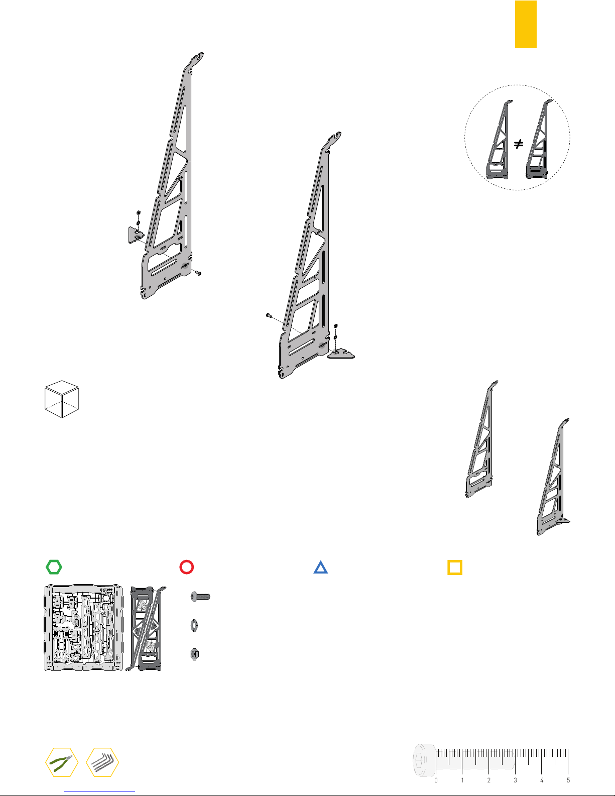
9
RULER
BACK
TOOLS
2
2
2
BUTTON HEAD SCREW DIN7380 M4X10
SERRATED LOCK WASHER DIN6798J M4
HEX. THIN NUT 1 DIN439 M4
STRUCTURE
MECHANICS
ELECTRONICS
PRINTED PARTS
A.2
01234
5
Page 12
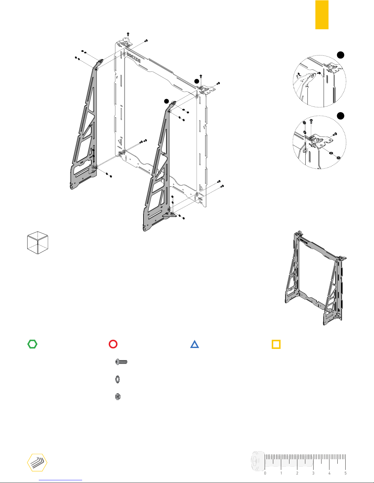
10
RULER
1
2
1
1
2
2
A.3
BACK
TOOLS
8
8
8
BUTTON HEAD SCREW DIN7380 M4X10
SERRATED LOCK WASHER DIN6798J M4
HEX. THIN NUT 1 DIN439 M4
STRUCTURE
MECHANICS
ELECTRONICS
PRINTED PARTS
01234
5
Page 13
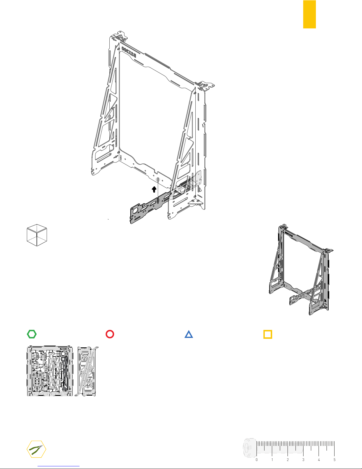
11
RULER
BACK
TOOLS
STRUCTURE
MECHANICS
ELECTRONICS
PRINTED PARTS
A.4
01234
5
Page 14
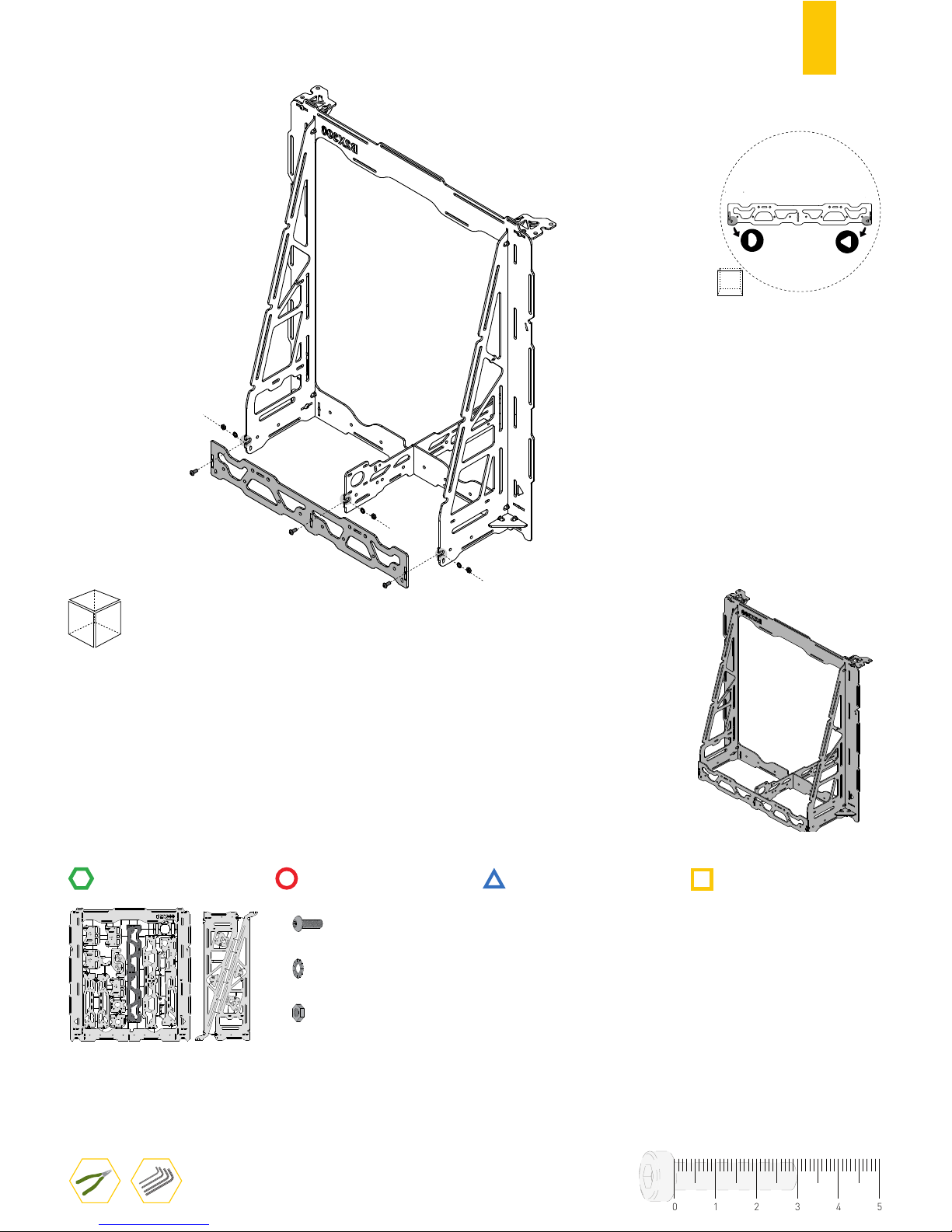
12
A.5
RULER
STRUCTURE
BACK
TOOLS
MECHANICS
3
3
3
BUTTON HEAD SCREW DIN7380 M4X10
SERRATED LOCK WASHER DIN6798J M4
HEX. THIN NUT 1 DIN439 M4
ELECTRONICS
PRINTED PARTS
BACK
LEFT
RIGHT
01234
5
Page 15
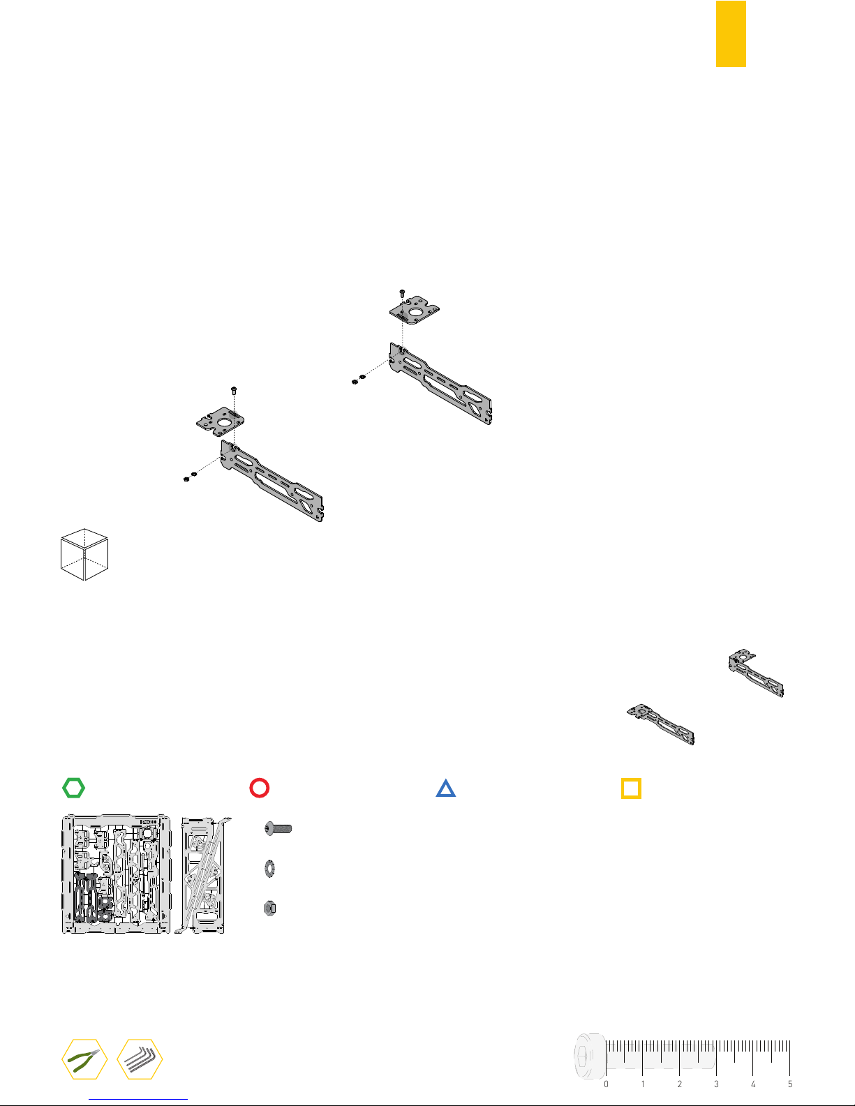
13
RULER
STRUCTURE
FRONT
TOOLS
MECHANICS
2
2
2
BUTTON HEAD SCREW DIN7380 M4X10
SERRATED LOCK WASHER DIN6798J M4
HEX. THIN NUT 1 DIN439 M4
ELECTRONICS
PRINTED PARTS
A.6
01234
5
Page 16
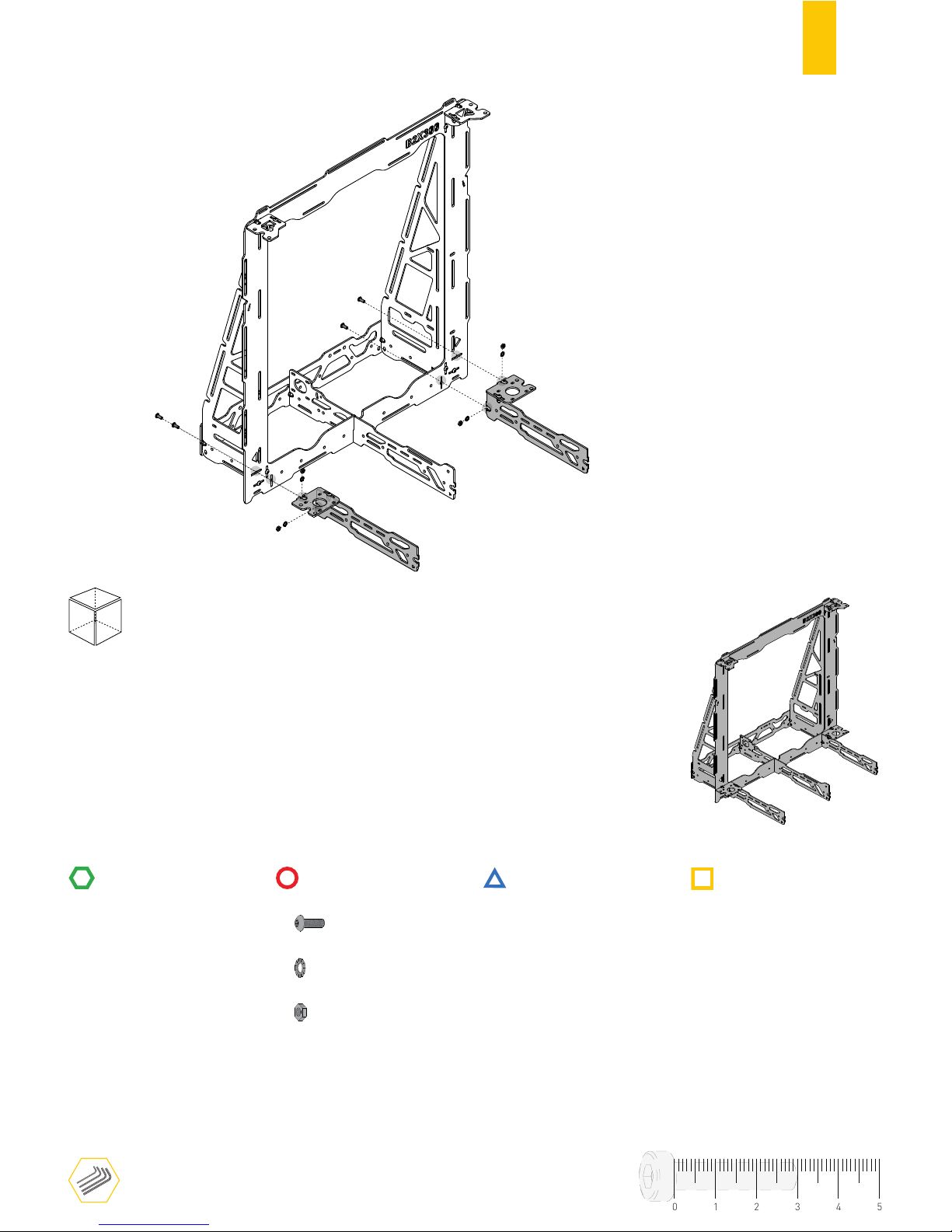
14
RULER
A.7
FRONT
TOOLS
4
4
4
STRUCTURE
MECHANICS
ELECTRONICS
PRINTED PARTS
BUTTON HEAD SCREW DIN7380 M4X10
SERRATED LOCK WASHER DIN6798J M4
HEX. THIN NUT 1 DIN439 M4
01234
5
Page 17
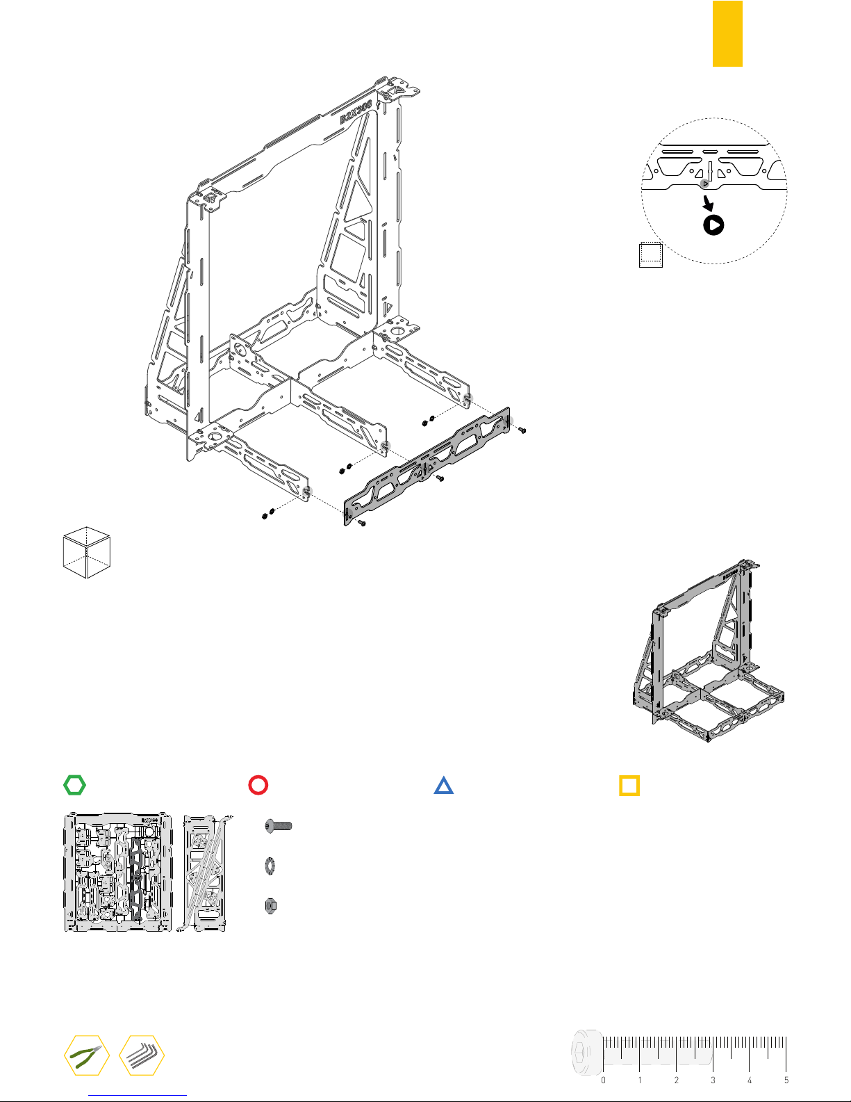
15
RULER
FRONT
TOOLS
3
3
3
STRUCTURE
MECHANICS
ELECTRONICS
PRINTED PARTS
BUTTON HEAD SCREW DIN7380 M4X10
SERRATED LOCK WASHER DIN6798J M4
HEX. THIN NUT 1 DIN439 M4
A.8
FRONT
LEFT RIGHT
01234
5
Page 18
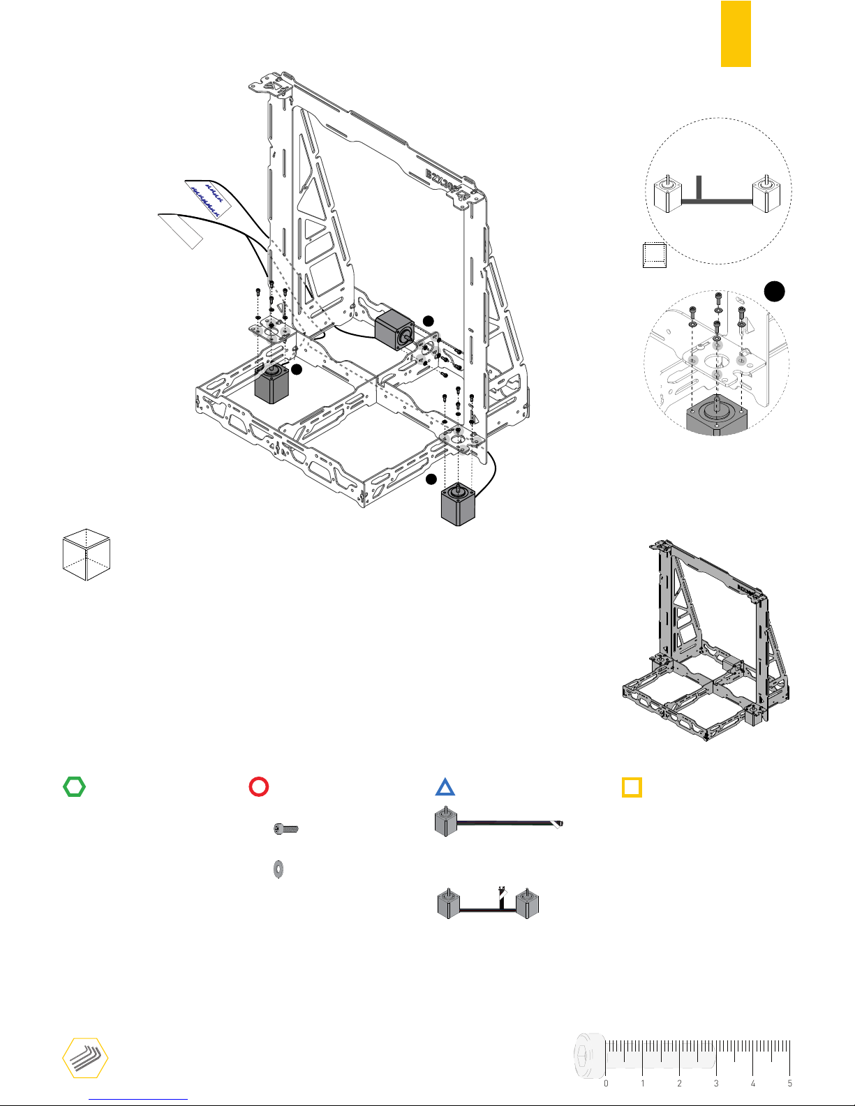
16
RULER
A.9
FRONT
TOOLS
CYL. HEAD SCREW DIN912 M3X6
12
12
PLAIN WASHER DIN125 M3
Δ
Y-AXIS
Δ
Z-AXIS
NEMA17 STEPPER MOTOR Y AXIS
NEMA17 STEPPER MOTORS Z AXIS
Δ
Y-AXIS
Δ
X-AXIS
Δ
EXTRUDER E0
Δ
Z-AXIS
1
1
1
STRUCTURE
MECHANICS
ELECTRONICS
PRINTED PARTS
01234
5
FRONT
LEFT RIGHT
Z-AXIS
Leave Y-AXIS and Z-AXIS
motors screws slightly loose.
BACK
1
⚠
Use the marker to select
Y-AXIS motor cable label.
Page 19
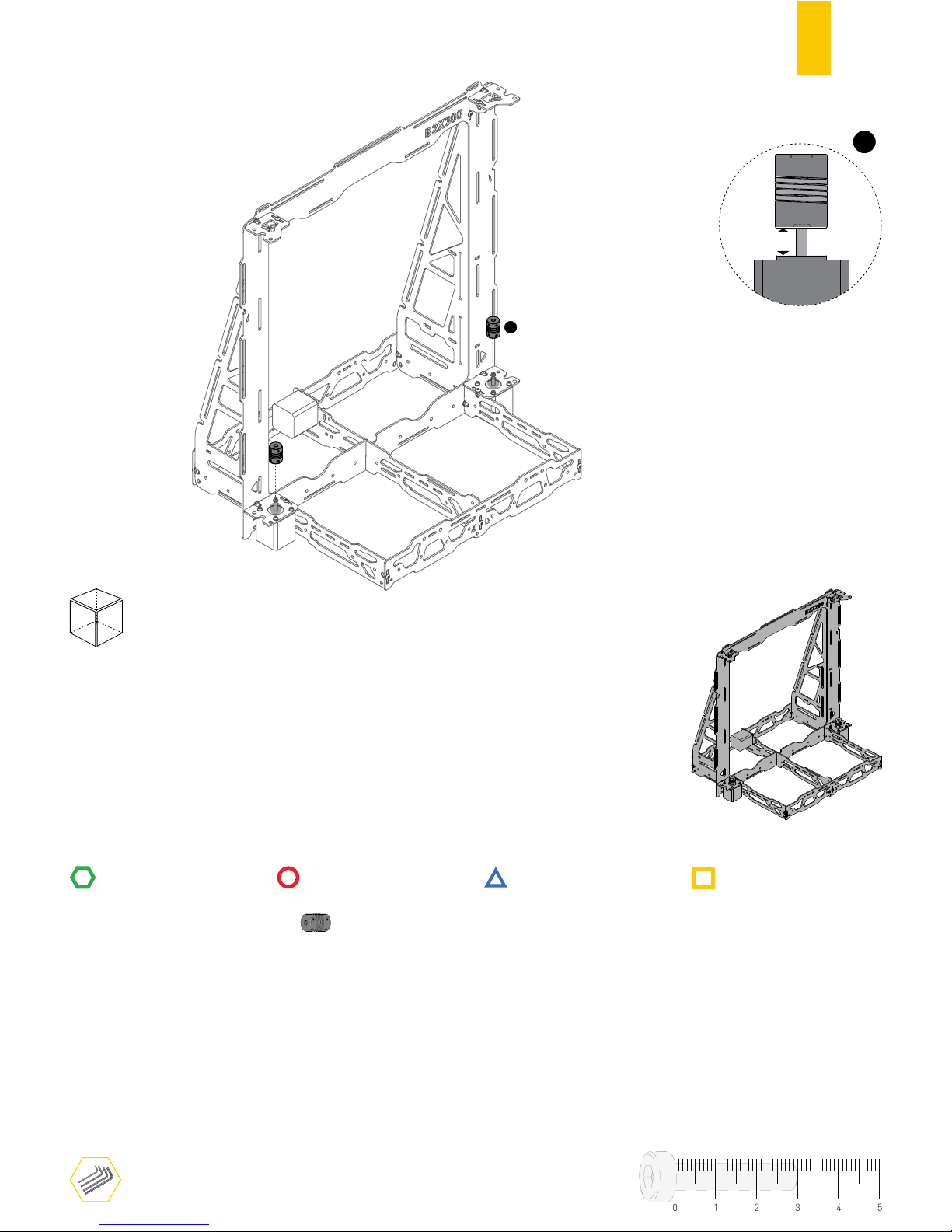
17
RULER
1
FRONT
FLEX COUPLING
2
TOOLS
STRUCTURE
MECHANICS
ELECTRONICS
PRINTED PARTS
A.10
1
5mm
˜
01234
5
Page 20
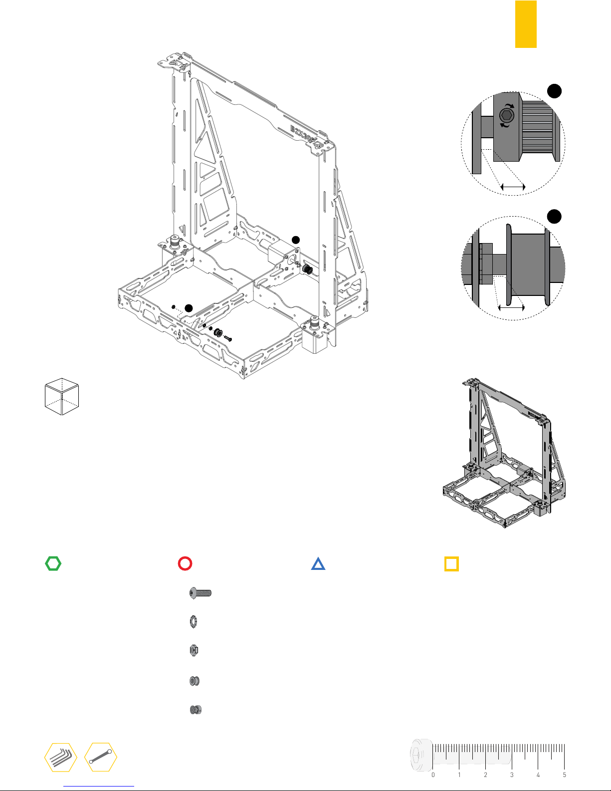
18
RULERRULER
A.11
1
2
FRONT
1
1mm
1mm
2
0.5mm
BUTTON HEAD SCREW DIN7380 M5X20
1
1
2
SERRATED LOCK WASHER DIN6798J M5
HEX. THIN NUT 1 DIN439 M5
FLAT BELT PULLEY
1
1
PULLEY GT2 20 TOOTH
TOOLS
STRUCTURE
MECHANICS
ELECTRONICS
PRINTED PARTS
01234
5
Page 21

19
B
ASSEMBLING
THE BUILD PLATE STRUCTURE
Page 22
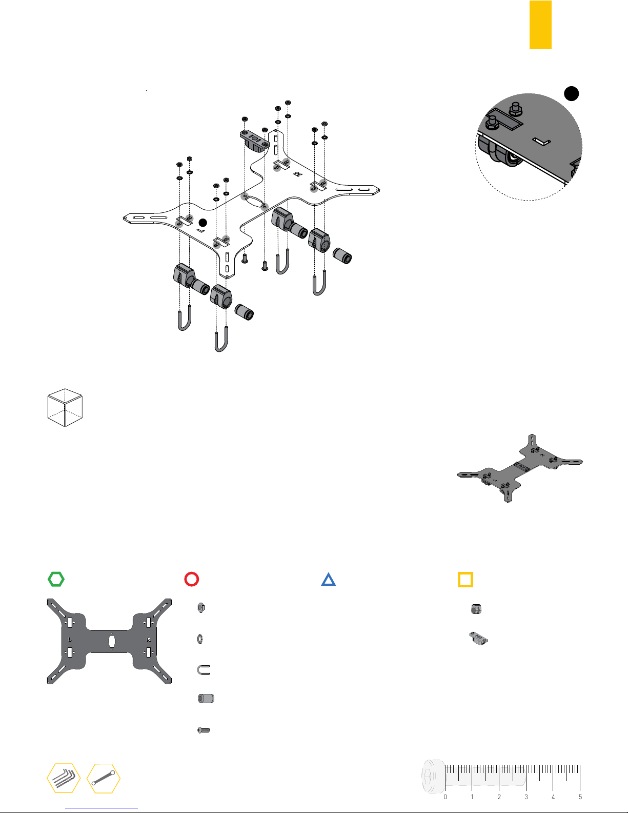
20
1
FRONT
“U” CLAMP M4
4
4
10
BED RAISER
HEX. THIN NUT 1 DIN439 M4
SERRATED LOCK WASHER DIN6798J M4
8
2
BUTTON HEAD SCREW DIN7380 M4X10
TOOLS
STRUCTURE
MECHANICS
ELECTRONICS
PRINTED PARTS
4
LINEAR BEARING 8øx25MM
BELT HOLDER
1
1
LEFT SIDE
B.1
01234
5
Do not over tighten the U clamps.
⚠
Page 23
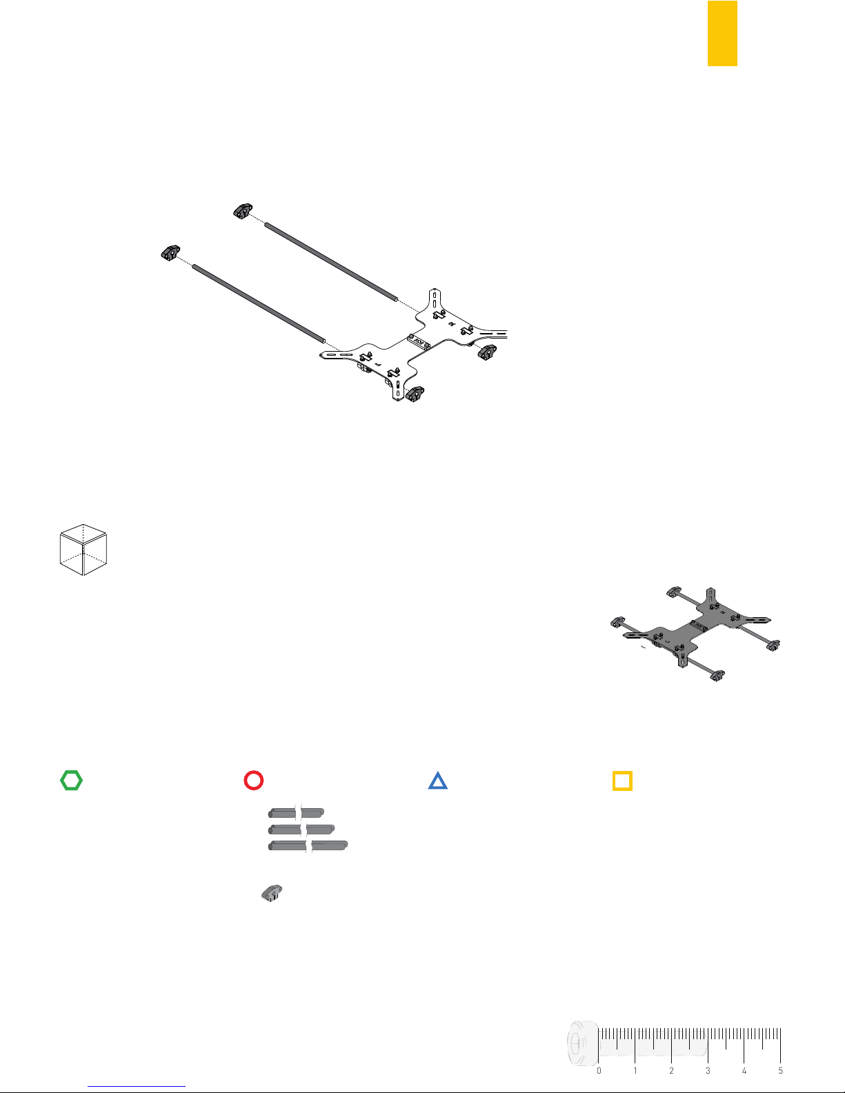
21
B.2
RULERRULER
FRONT
TOOLS
STRUCTURE
MECHANICS
ELECTRONICS
PRINTED PARTS
4
GUIDE SUPPORT
2
LINEAR GUIDE 8ø x 360MM
01234
5
✓
✗
✗
No tools needed
Page 24
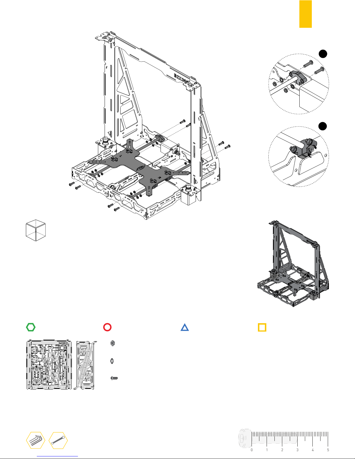
22
RULERRULER
FRONT
8
HEX. THIN NUT 1 DIN439 M5
SERRATED LOCK WASHER DIN6798J M5
8
8
BUTTON HEAD SCREW DIN7380 M5X20
TOOLS
STRUCTURE
MECHANICS
ELECTRONICS
PRINTED PARTS
1º
2º
B.3
01234
5
Page 25
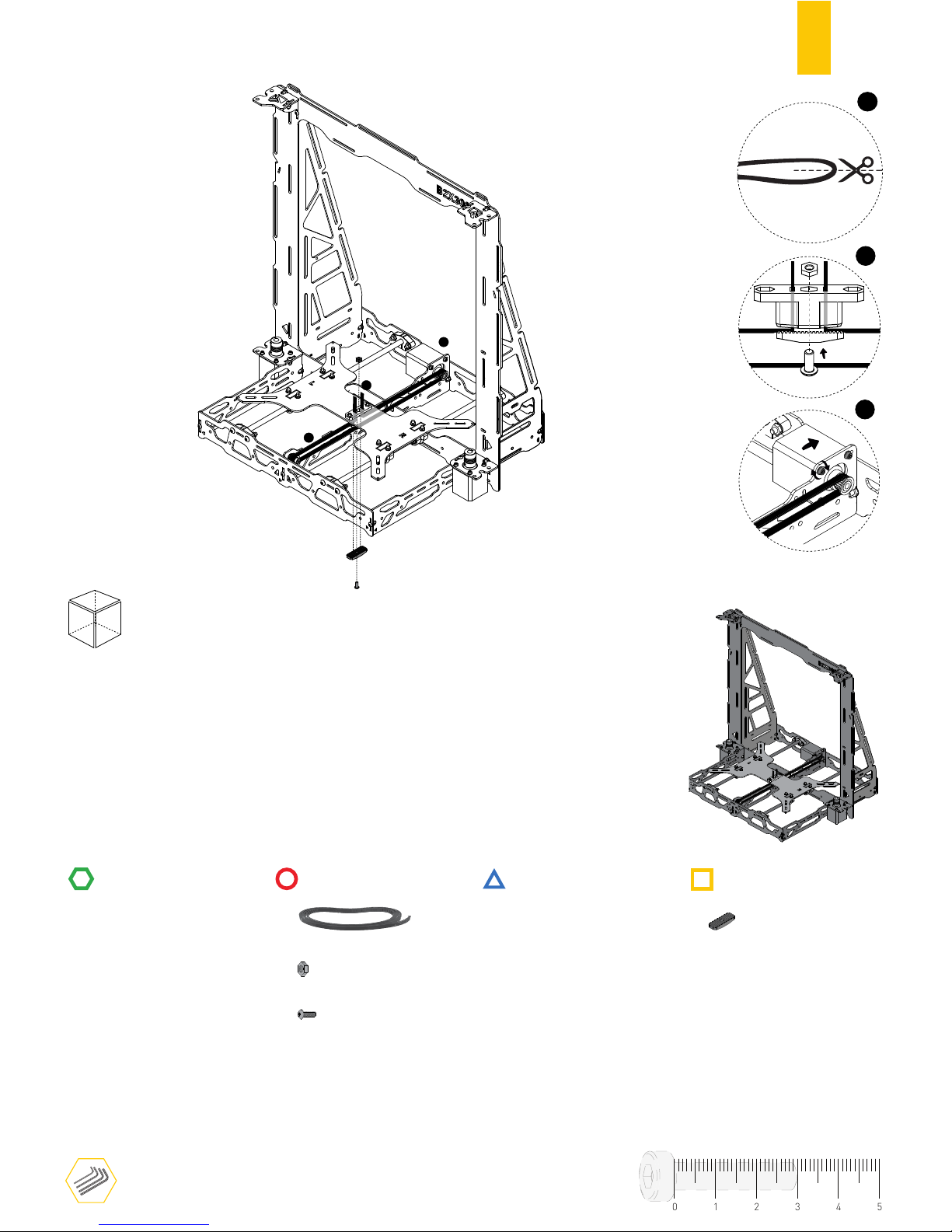
23
B.4
RULERRULER
FRONT
TOOLS
STRUCTURE
MECHANICS
ELECTRONICS
PRINTED PARTS
BELT HOLDER LOCK
1
GT2 RUBBER BELT -0,80m
2
3
1
1
HEX. THIN NUT 1 DIN439 M4
1
BUTTON HEAD SCREW DIN7380 M4X20
2
3
Push back Y-AXIS motor to stretch the
rubber belt and finish tightening the screws.
01234
5
1
1
1,20m
0,80m
Cut rubber belt
Page 26
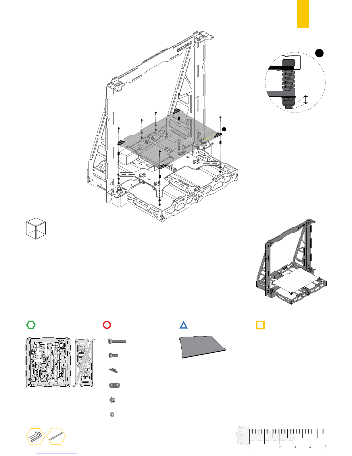
24
1
FRONT
BUILD PLATAFORM SPRING
4
4
CYL. HEAD SCREW DIN912 M3X20
BUILD PLATAFORM CLIP
4
TOOLS
STRUCTURE
MECHANICS
ELECTRONICS
PRINTED PARTS
PCB HEATED BED 314X214MM
6
6
HEX. THIN NUT 1 DIN10511 M3
PLAIN WASHER DIN125 M3
B.5
01234
5
~1mm
1
2
CYL. HEAD SCREW DIN912 M3X6
Page 27

25
C
ASSEMBLING THE X-AXIS
Page 28
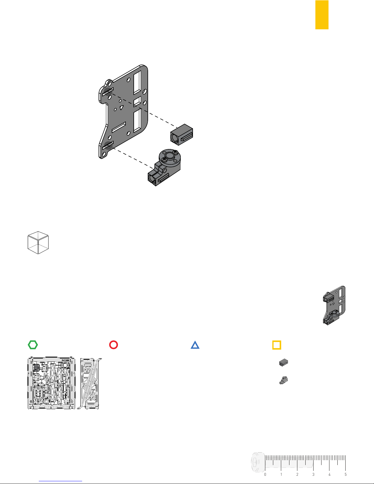
26
RULERRULER
FRONT
TOOLS
STRUCTURE
MECHANICS
ELECTRONICS
PRINTED PARTS
X SUPPORT
1
C.1
01234
5
X SUPPORT WITH TRAPEZOIDAL NUT
1
No tools needed
Page 29
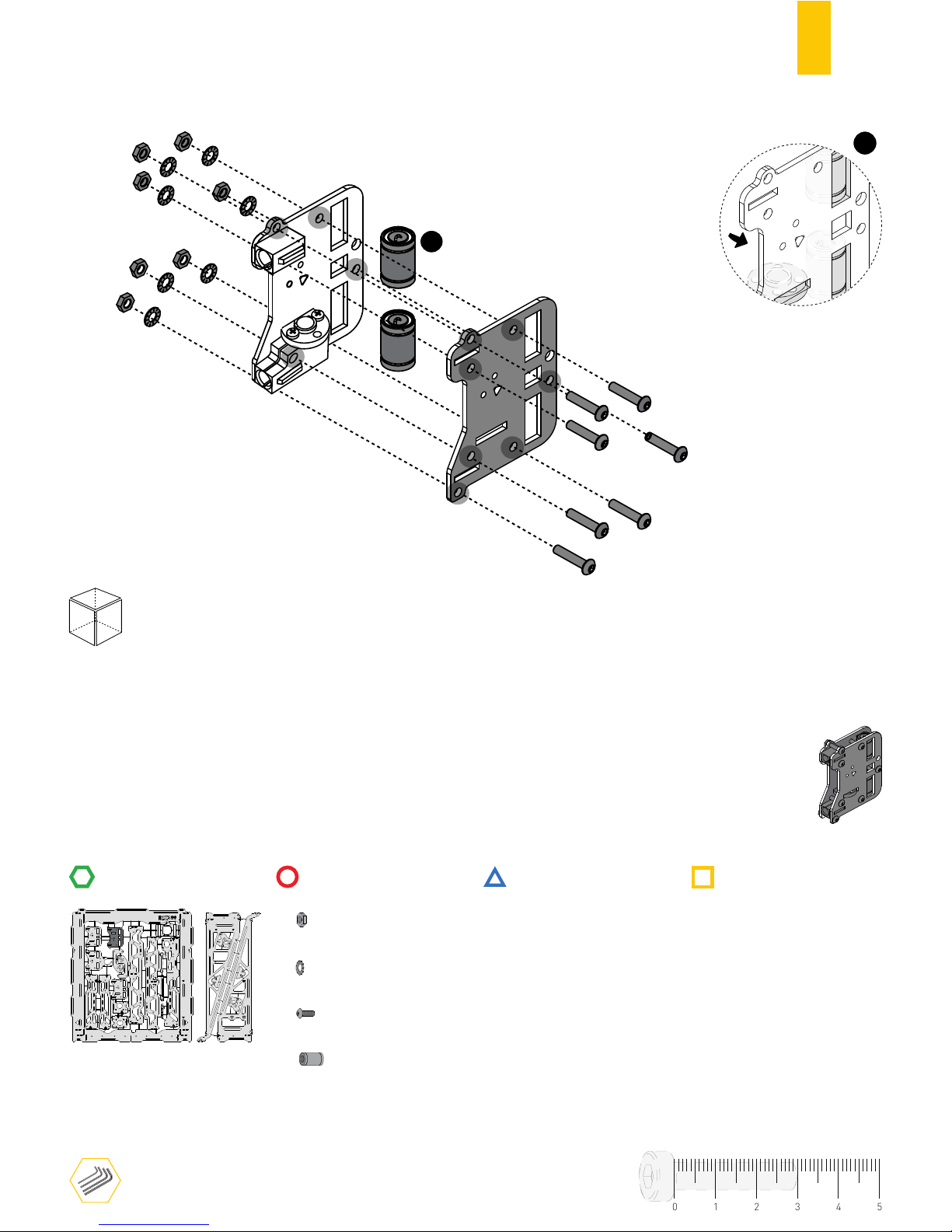
27
C.2
RULERRULER
1
FRONT
7
HEX. THIN NUT 1 DIN439 M4
SERRATED LOCK WASHER DIN6798J M4
7
2
7
BUTTON HEAD SCREW DIN7380 M4X20
TOOLS
STRUCTURE
MECHANICS
ELECTRONICS
PRINTED PARTS
1
01234
5
Leave all screws slightly loose.
⚠
LINEAR BEARING 8øx25MM
Page 30
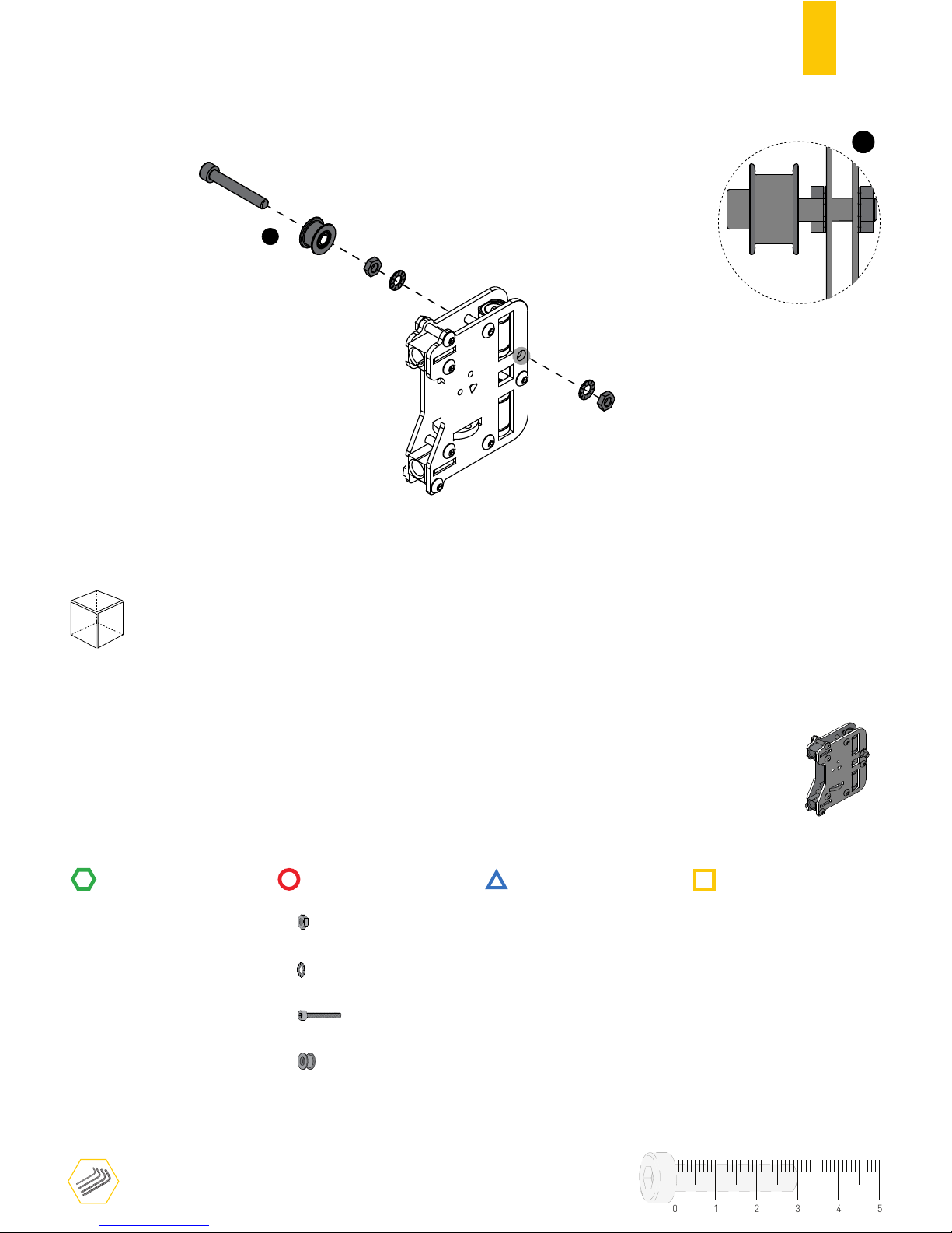
28
RULERRULER
FRONT
TOOLS
STRUCTURE
MECHANICS
ELECTRONICS
PRINTED PARTS
1
2
HEX. THIN NUT 1 DIN439 M5
SERRATED LOCK WASHER DIN6798J M5
2
1
CYL. HEAD SCREW DIN912 M5X35
1
FLAT BELT PULLEY
C.3
1
01234
5
Page 31
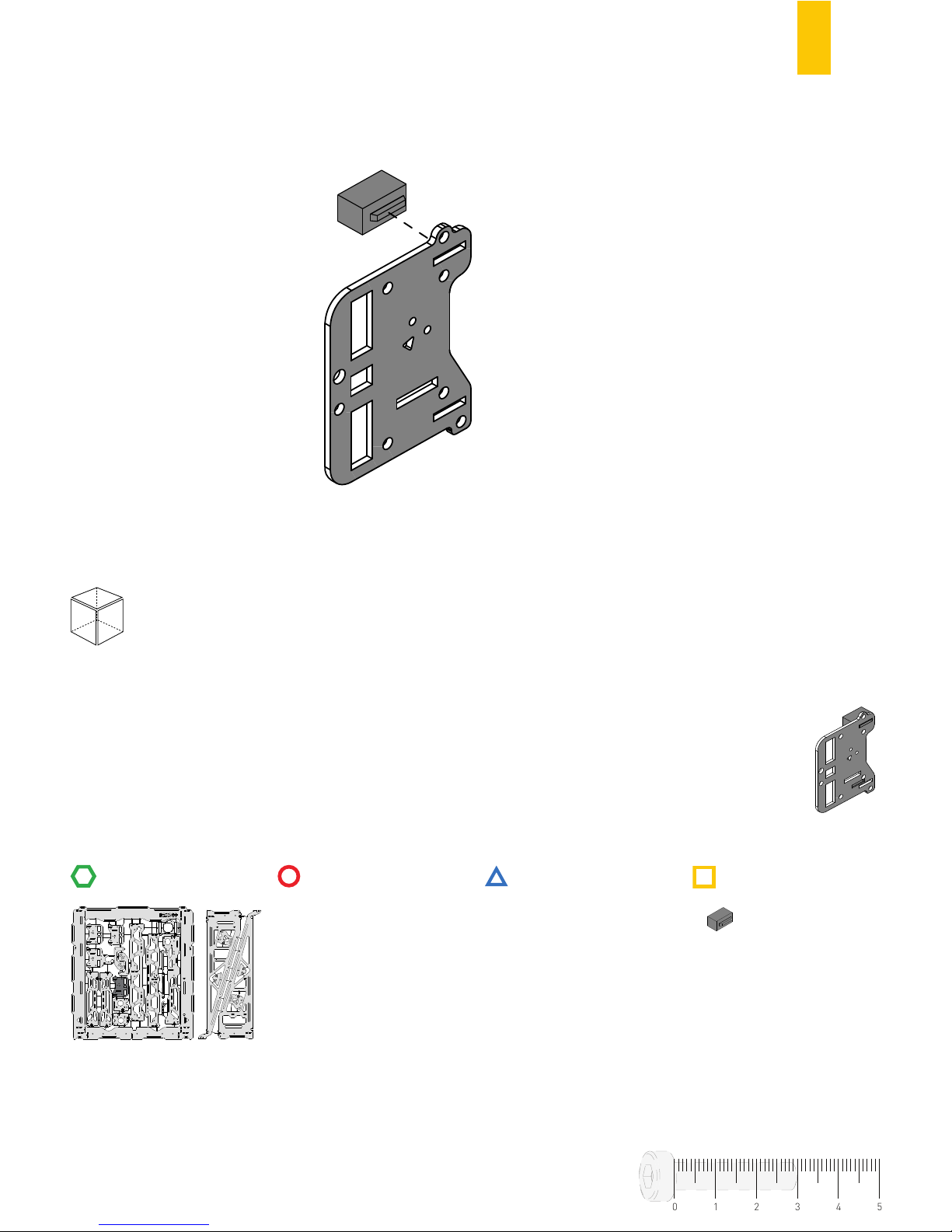
29
C.4
RULER
FRONT
TOOLS
STRUCTURE
MECHANICS
ELECTRONICS
PRINTED PARTS
01234
5
No tools needed
X SUPPORT
1
Page 32
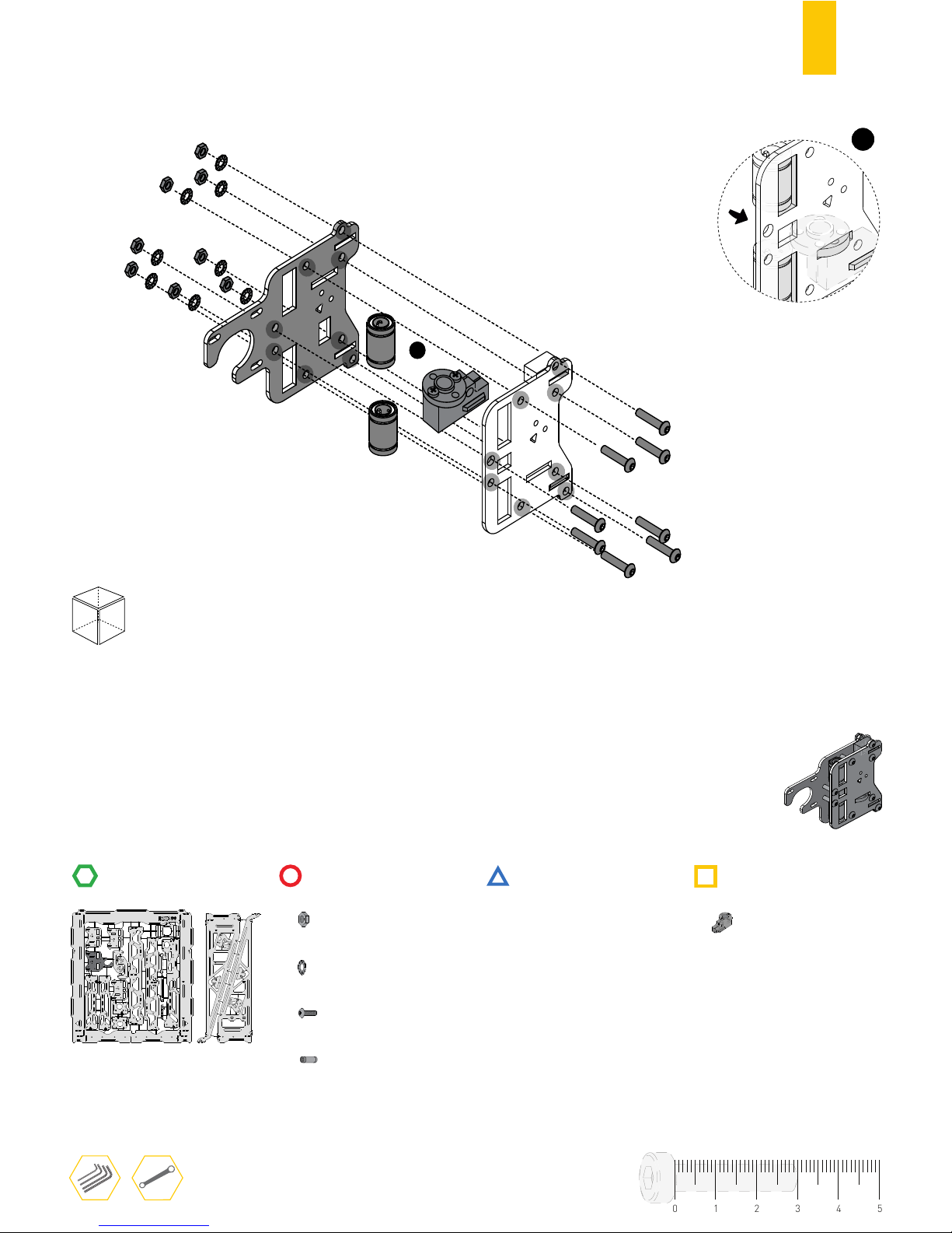
30
RULER
FRONT
TOOLS
STRUCTURE
MECHANICS
ELECTRONICS
PRINTED PARTS
1
1
8
HEX. THIN NUT 1 DIN439 M4
SERRATED LOCK WASHER DIN6798J M4
8MM LINEAR BEARING
8
2
8
BUTTON HEAD SCREW DIN7380 M4X20
C.5
X SUPPORT WITH TRAPEZOIDAL NUT
1
01234
5
Leave all screws slightly loose.
⚠
Page 33
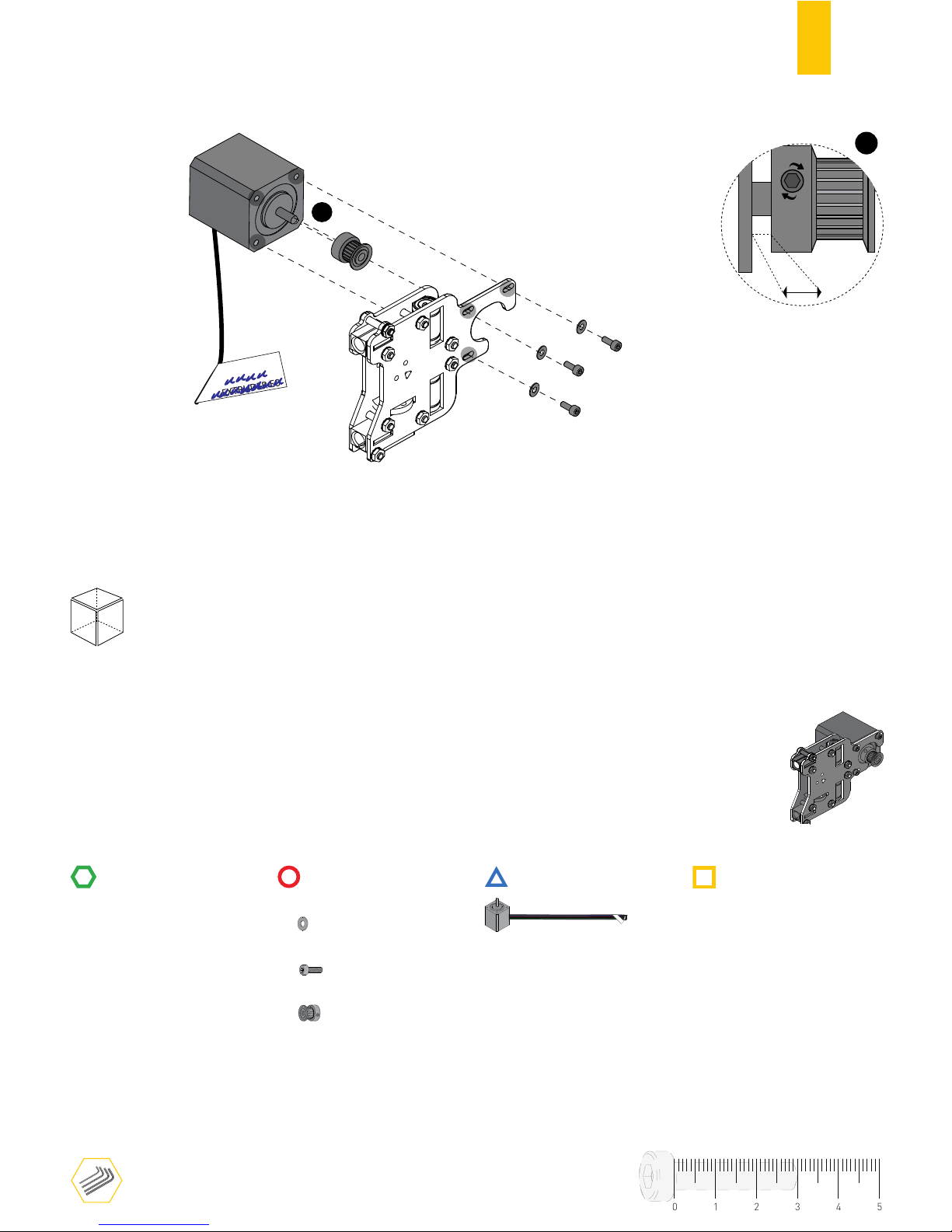
31
C.6
RULERRULER
1
Δ
Y-AXIS
Δ
X-AXIS
Δ
EXTRUDER E0
BACK
1
PULLEY GT2 20 TOOTH
PLAIN WASHER DIN125 M3
3
3
CYL. HEAD SCREW DIN912 M3X6
TOOLS
STRUCTURE
MECHANICS
ELECTRONICS
PRINTED PARTS
1
1mm
Δ
Y-AXIS
X AXIS NEMA17 STEPPER MOTOR
01234
5
Use the marker to label the
cable label with X-AXIS selected
Page 34
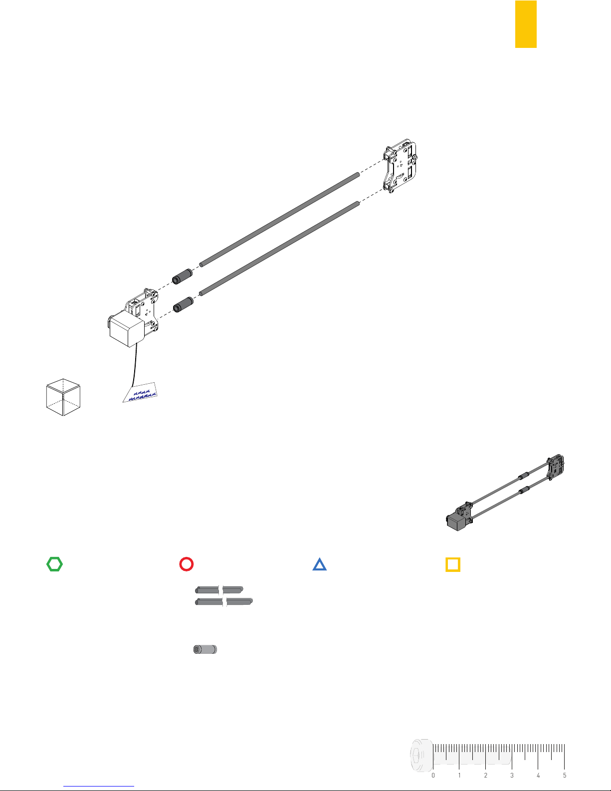
32
RULERRULER
FRONT
TOOLS
STRUCTURE
MECHANICS
ELECTRONICS
PRINTED PARTS
Δ
Y-AXIS
Δ
X-AXIS
Δ
EXTRUDER E0
2
LINEAR BEARING 8ø x 45MM
C.7
01234
5
Linear guides should be pushed to
the end to fit well enough.
⚠
2
LINEAR GUIDE 8ø x 410MM
✗
✗
✓
Page 35

33
D
ASSEMBLING THE X-AXIS
TO THE STRUCTURE
Page 36
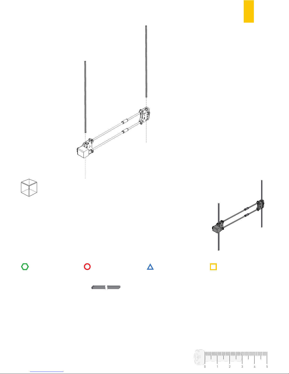
34
RULERRULER
FRONT
TOOLS
STRUCTURE
MECHANICS
ELECTRONICS
PRINTED PARTS
D.1
01234
5
2
LINEAR GUIDE 8ø x 485MM
✗
Page 37
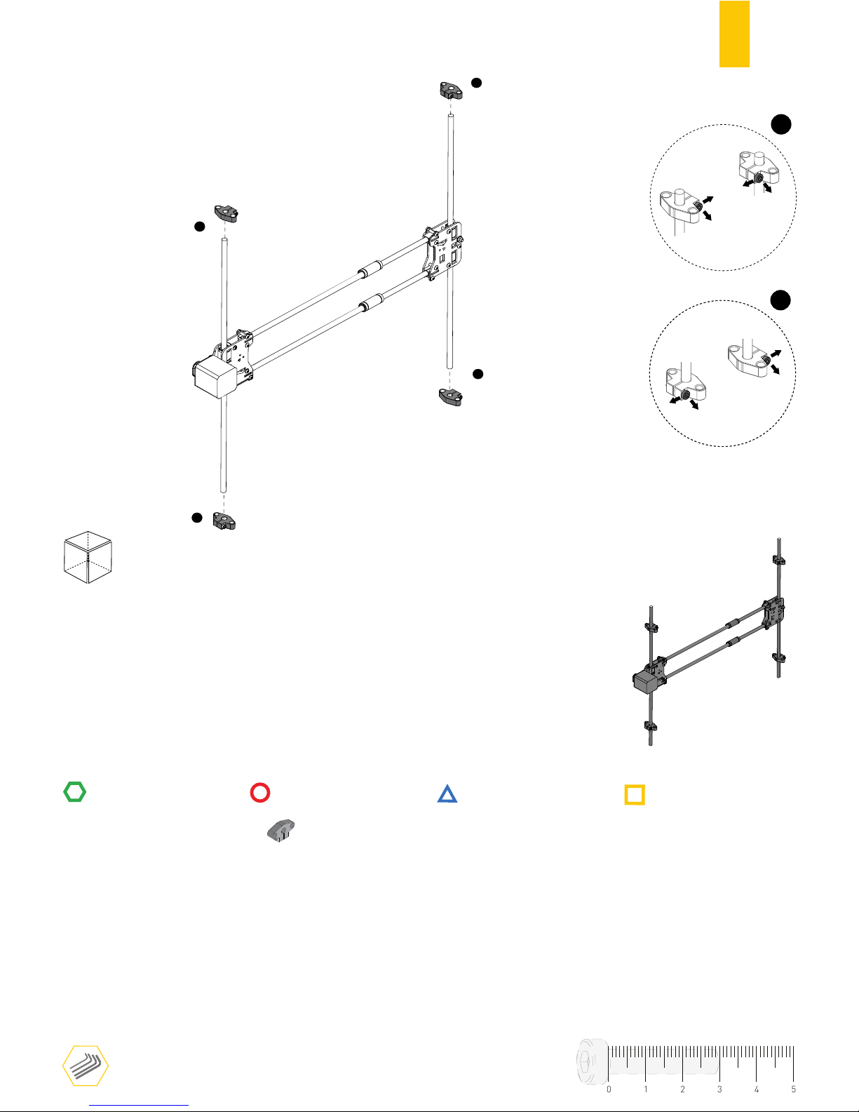
35
D.2
RULERRULER
2
1
2
1
FRONT
TOOLS
STRUCTURE
MECHANICS
ELECTRONICS
PRINTED PARTS
4
GUIDE SUPPORT
01234
5
2
BOTTOM
SCREW FACING
FRONT AND OUTWARD
1
SCREW FACING
FRONT AND INWARD
TOP
Page 38
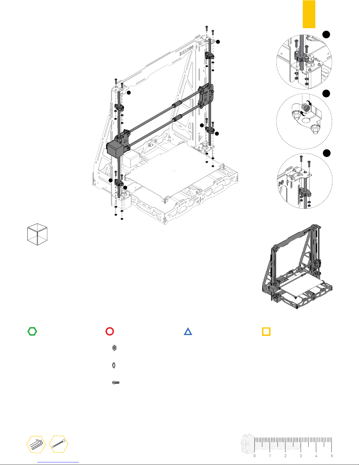
36
RULERRULER
FRONT
TOOLS
STRUCTURE
MECHANICS
ELECTRONICS
PRINTED PARTS
1
1
2
2
3
3
D.3
8
HEX. THIN NUT 1 DIN439 M5
SERRATED LOCK WASHER DIN6798J M5
8
8
BUTTON HEAD SCREW DIN7380 M5X20
3
2
01234
5
1
Leave TOP guide supports slightly loose.
⚠
Page 39
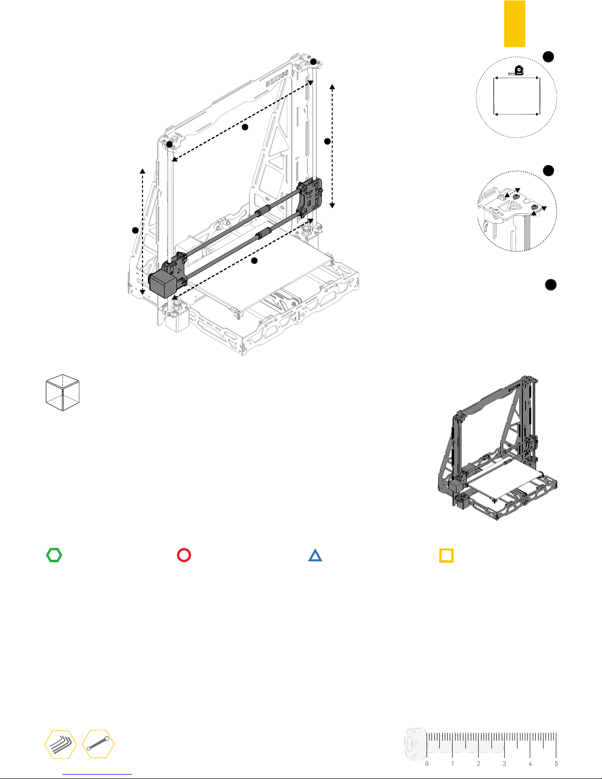
37
RULERRULER
FRONT
TOOLS
STRUCTURE
MECHANICS
ELECTRONICS
PRINTED PARTS
1
2
2
1
3
3
D.4
1
with BOTTOM distance
between linear guides
Match TOP
2
Adjust it within slot holes
01234
5
Check if X-AXIS flows
freely in the linear guides
3
Page 40
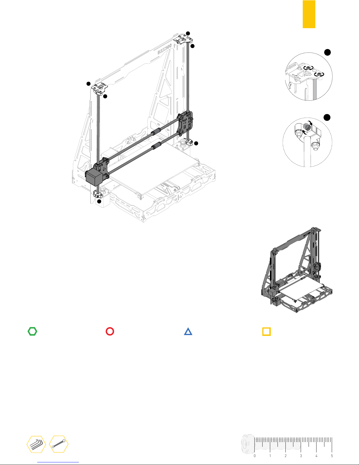
38
D.5
1
2
2
1
2
2
2
1
Finish tightening the screws
RULERRULER
TOOLS
STRUCTURE
MECHANICS
ELECTRONICS
PRINTED PARTS
01234
5
Page 41
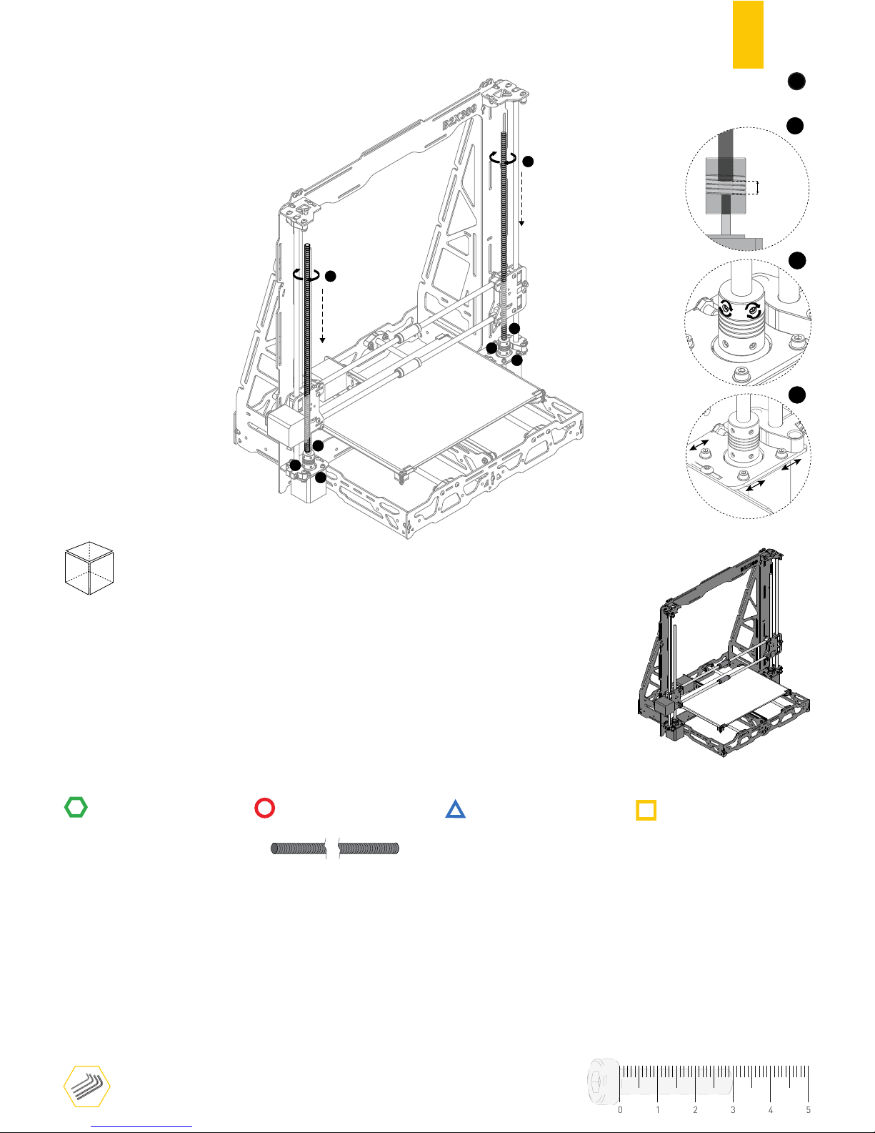
39
D.6
RULER
RULER
1
1
2
2
4
4
3
3
FRONT
TOOLS
STRUCTURE
MECHANICS
ELECTRONICS
PRINTED PARTS
2
THREADED ROD 400MM
3
1
01234
5
4
1
Screw in the threaded rods into the
flex couplings (clock wise rotation)
1
2
5mm
˜
Leave gap between
rod and motor shaft
Threaded rod must be parallel to the
guide, adjust it within motors slot holes.
Page 42

40
E
ASSEMBLING THE EXTRUDER
Page 43
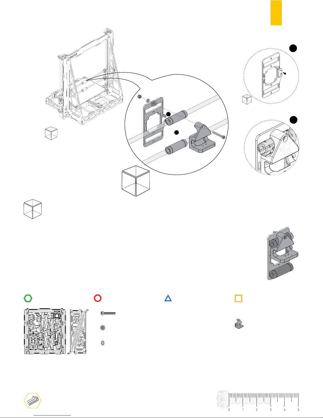
41
STRUCTURE
MECHANICS
ELECTRONICS
PRINTED PARTS
RULER
TOOLS
2
1
FRONT
E.1
LINEAR BEARING SUPPORT
2
1
CYL. HEAD SCREW DIN912 M3X25
1
1
HEX. THIN NUT 1 DIN10511 M3
PLAIN WASHER DIN125 M3
BACK
01234
5
Do not over tighten the screw
⚠
BACK
RIGHT
1
BACK
Page 44
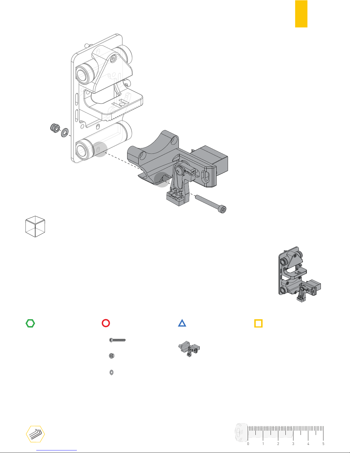
42
STRUCTURE
MECHANICS
ELECTRONICS
PRINTED PARTS
RULER
TOOLS
BACK
E.2
AUTO-CALIBRATION MODULE
1
CYL. HEAD SCREW DIN912 M3X25
1
1
HEX. THIN NUT 1 DIN10511 M3
PLAIN WASHER DIN125 M3
01234
5
Page 45
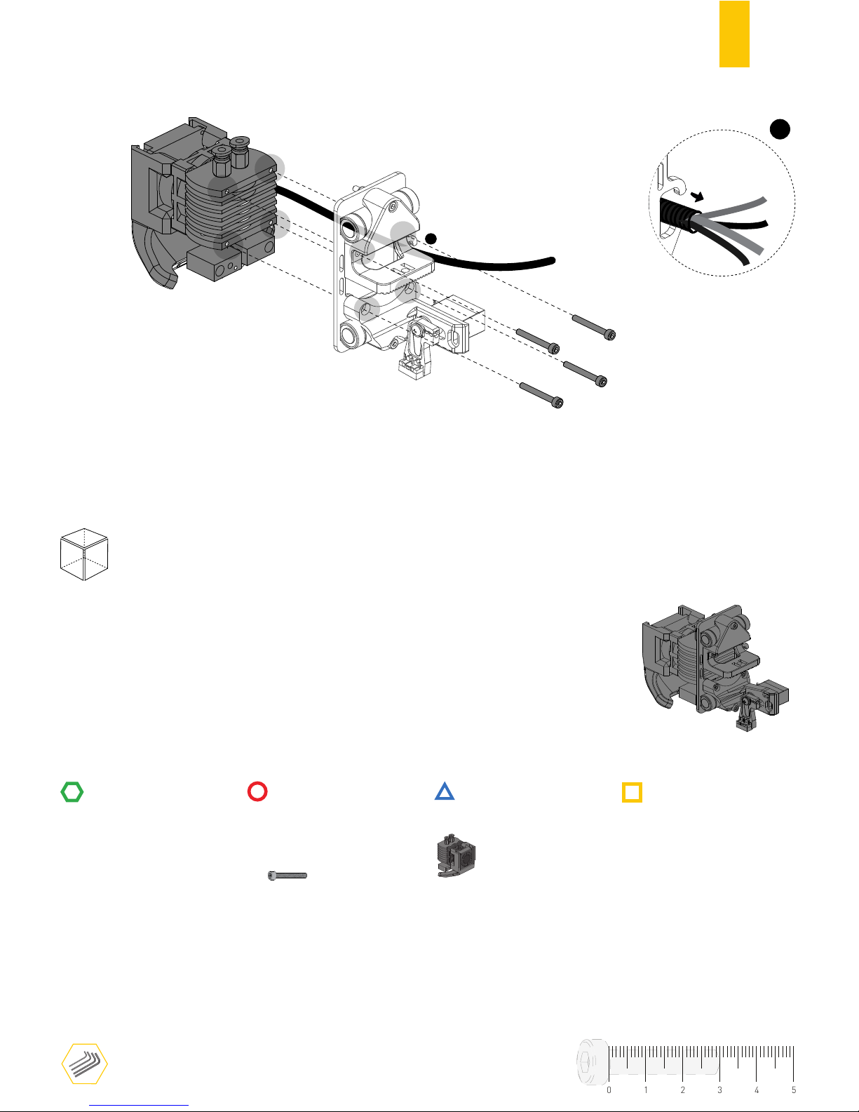
43
STRUCTURE
MECHANICS
ELECTRONICS
PRINTED PARTS
RULER
TOOLS
1
BACK
E.3
BOWDEN EXTRUDER
4
CYL. HEAD SCREW DIN912 M3X20
1
01234
5
Page 46
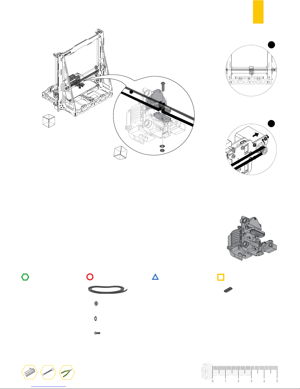
44
STRUCTURE
MECHANICS
ELECTRONICS
PRINTED PARTS
RULER
TOOLS
1
BACK
E.4
BELT HOLDER LOCK
1
GT2 RUBBER BELT
1
HEX. THIN NUT 1 DIN439 M4
SERRATED LOCK WASHER DIN6798J M4
1
1
BUTTON HEAD SCREW DIN7380 M4X20
1
BACK
01234
5
2
Push back X-AXIS MOTOR to stretch the
rubber belt and finish tightening the screws.
Fasten the belt holder slightly, then
push the rubber belt with a pliers and
finish tightening the screw.
Page 47
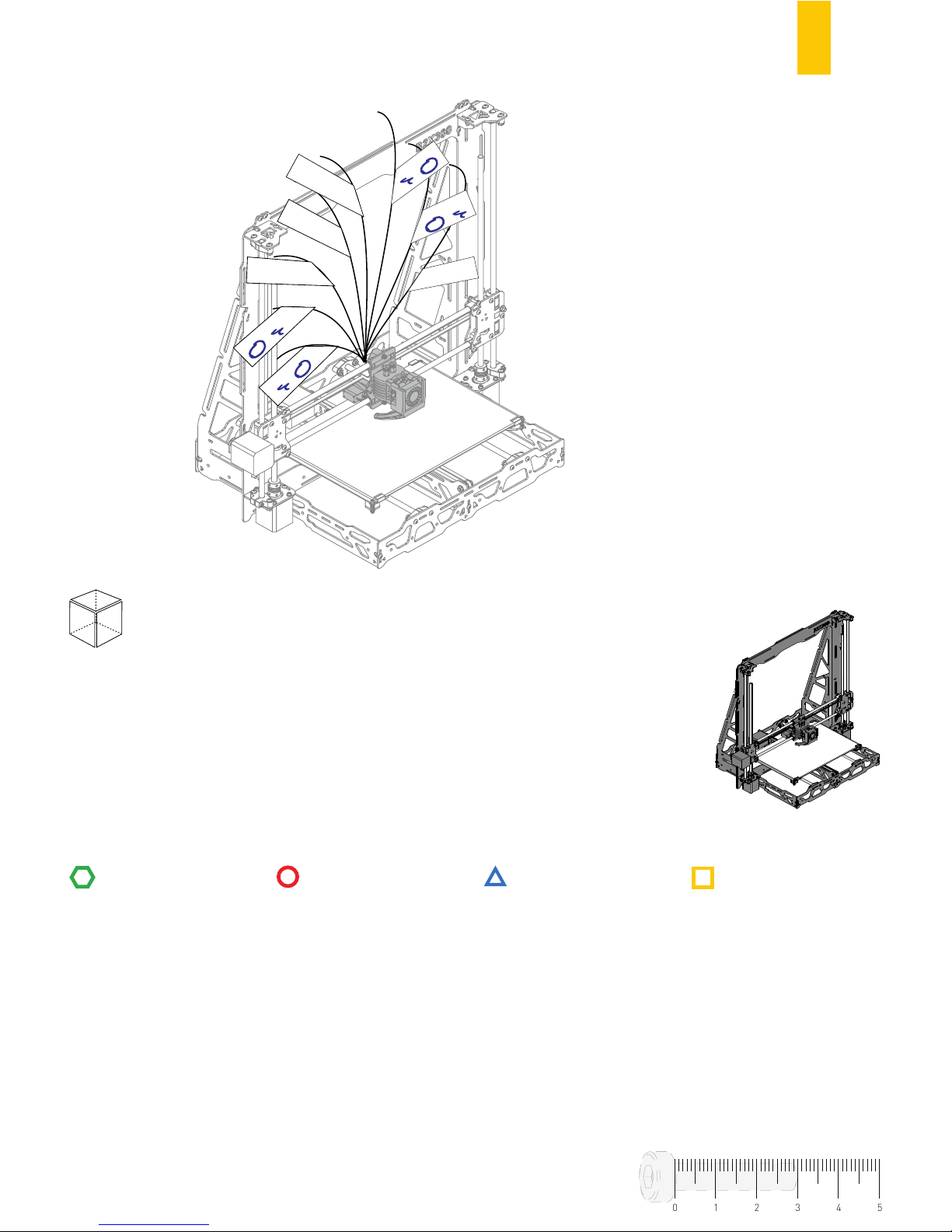
45
STRUCTURE
MECHANICS
ELECTRONICS
PRINTED PARTS
RULER
TOOLS
Δ Blower
Δ Heater
[E0] [E1]
Δ Heater
[E0] [E1]
Δ
CAL:SERVOS1
Δ
EXT - FAN
Δ
CAL:Z-/(J9)
Δ
EXTRUDER SENSOR
[E0] [E1]
Δ
EXTRUDER SENSOR
[E0] [E1]
FRONT
E.5
01234
5
Page 48
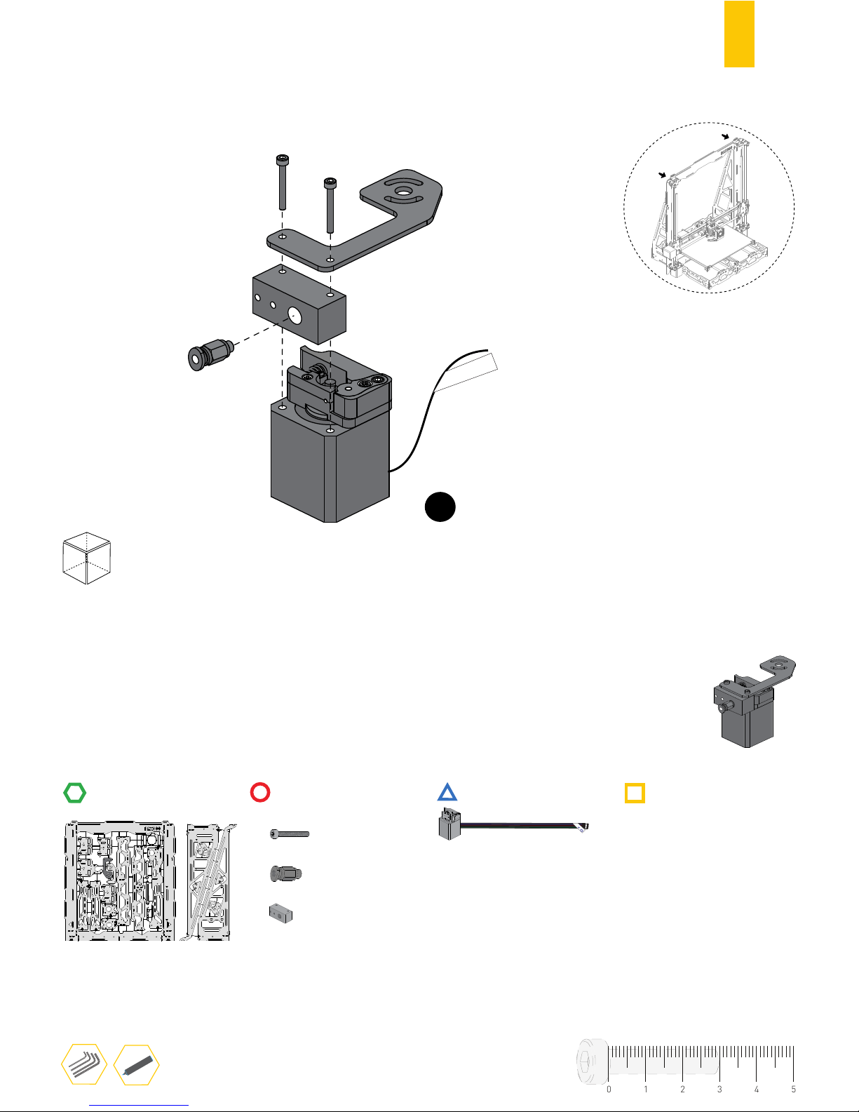
46
E.6
RULERRULER
E1
Δ
EXTRUDER E1
FRONT
TOOLS
STRUCTURE
MECHANICS
ELECTRONICS
PRINTED PARTS
2
CYL. HEAD SCREW DIN912 M3X25
1
PTFE COUPLER
1
DRIVER BLOCK
Δ
EXTRUDER
[E0] [E1]
EXTRUDER DRIVER 1
01234
5
E0
E1
Page 49
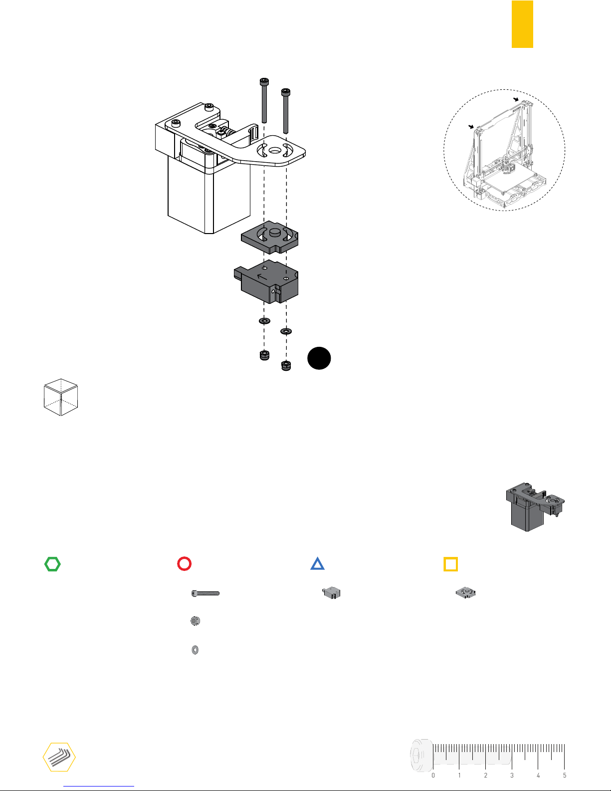
47
E.7
RULER
E1
BACK
TOOLS
STRUCTURE
MECHANICS
ELECTRONICS
PRINTED PARTS
2
CYL. HEAD SCREW DIN912 M3X30
2
2
HEX. THIN NUT 1 DIN10511 M3
PLAIN WASHER DIN125 M3
1
DRIVER SENSOR SPACER
1
FILAMENT DETECTION MODULE
01234
5
E0
E1
Leave all screws slightly loose.
⚠
Page 50
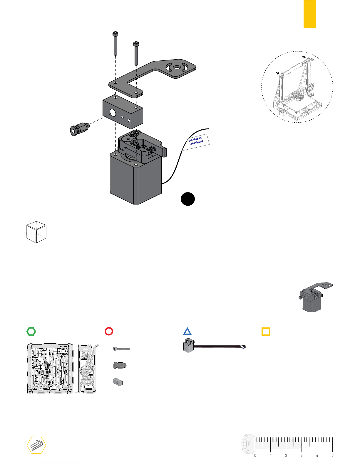
48
STRUCTURE
MECHANICS
ELECTRONICS
PRINTED PARTS
RULER
TOOLS
Δ
Y-AXIS
Δ
X-AXIS
Δ
EXTRUDER E0
E0
FRONT
E.8
2
CYL. HEAD SCREW DIN912 M3X25
1
PTFE COUPLER
1
DRIVER BLOCK
Δ
EXTRUDER
[E0] [E0]
EXTRUDER DRIVER 0
Use the marker to label the
cable label with E0 selected
01234
5
E0
E1
Page 51
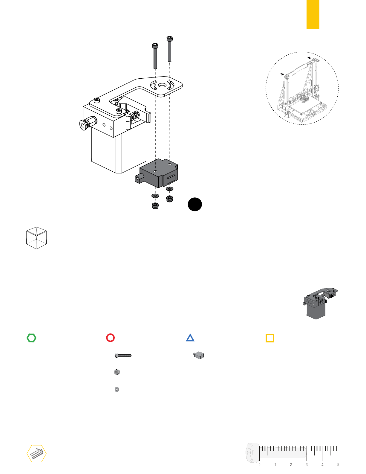
49
E.9
RULER
E0
FRONT
TOOLS
STRUCTURE
MECHANICS
ELECTRONICS
PRINTED PARTS
2
CYL. HEAD SCREW DIN912 M3X30
2
2
HEX. THIN NUT 1 DIN10511 M3
PLAIN WASHER DIN125 M3
1
FILAMENT DETECTION MODULE
01234
5
E0
E1
Leave all screws slightly loose.
⚠
Page 52
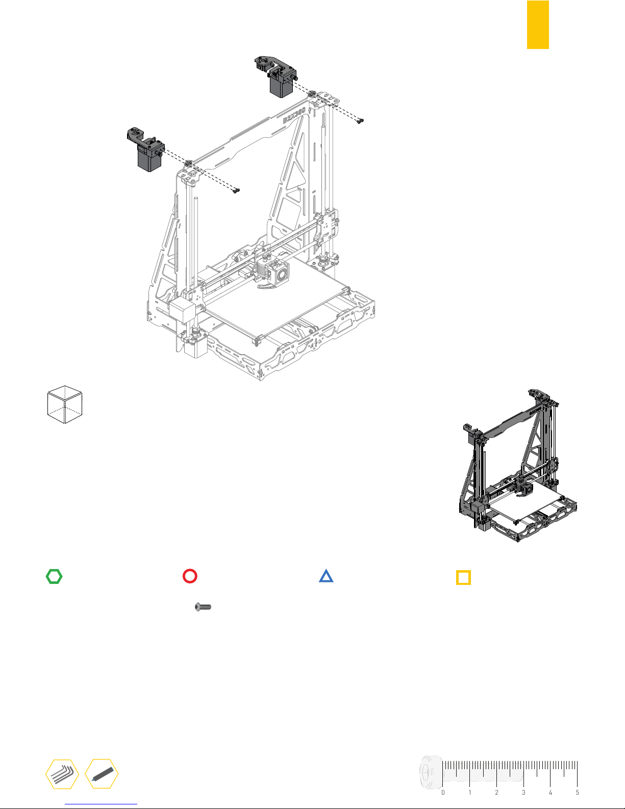
50
STRUCTURE
MECHANICS
ELECTRONICS
PRINTED PARTS
RULER
TOOLS
E0
E1
FRONT
E.10
4
BUTTON HEAD SCREW DIN7380 M4X10
01234
5
Page 53

51
F
ASSEMBLING THE ELECTRONICS
Page 54
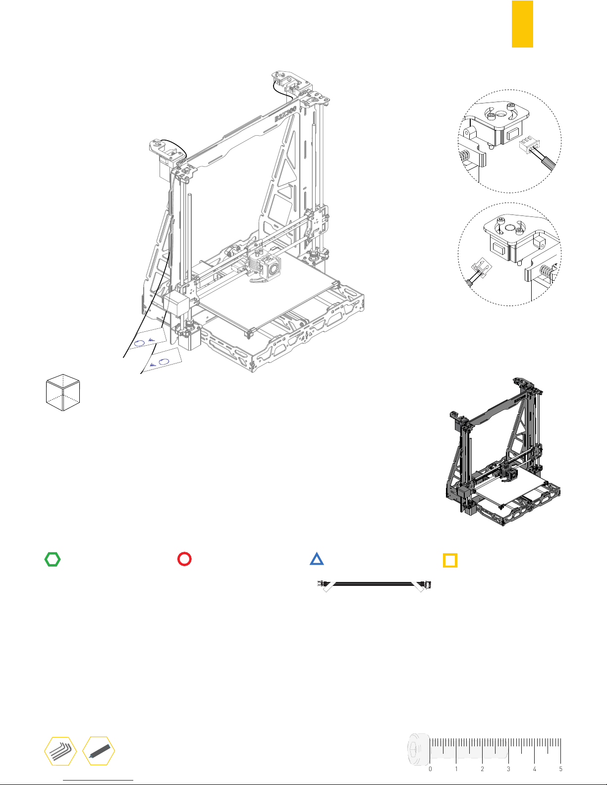
52
STRUCTURE
MECHANICS
ELECTRONICS
PRINTED PARTS
RULER
TOOLS
Δ FILAMENT
[E0] [E1]
Δ FILAMENT
[E0] [E1]
E0
E1
FRONT
F.1
Δ FILAMENT
[E0] [E1]
Δ FILAMENT
[E0] [E1]
FILAMENT SENSOR CABLE
2
Use the marker to label both
labels of each cables with E0
and E1.
01234
5
E1
1
E1
2
E0
Page 55
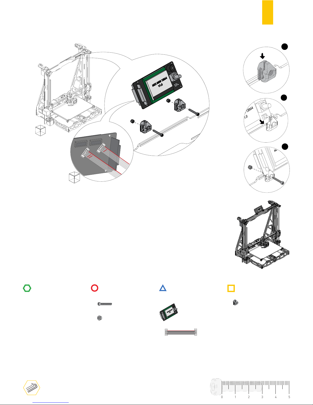
53
STRUCTURE
MECHANICS
ELECTRONICS
PRINTED PARTS
RULER
TOOLS
BACK
EXP2
EXP1
F.2
DISPLAY_SUPPORT
DISPLAY MK3 MINI 12864
1º
2º
3º
FRONT
2
2
CYL. HEAD SCREW DIN912 M3X20
2
HEX. THIN NUT 1 DIN10511 M3
CONTROL PANEL CABLE
2
01234
5
Red line must be on the right side
Page 56
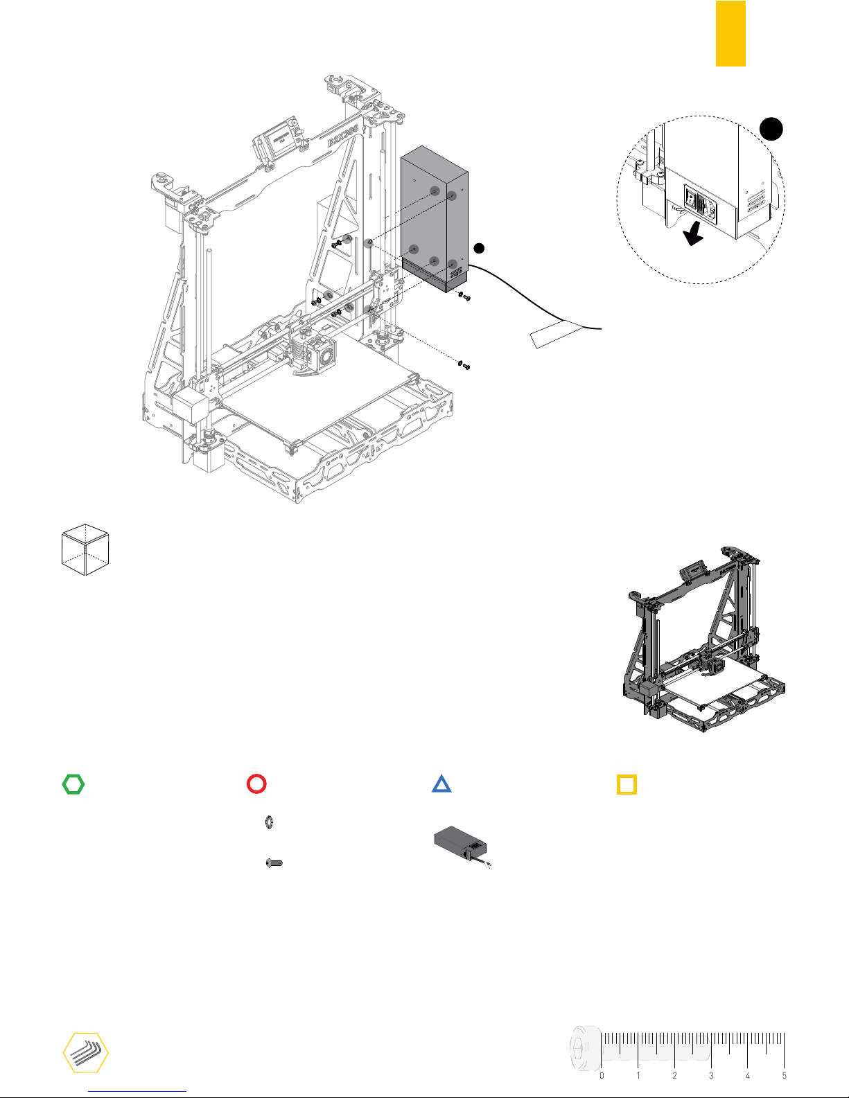
54
STRUCTURE
MECHANICS
ELECTRONICS
PRINTED PARTS
RULER
TOOLS
Δ
24 VDC
1
FRONT
F.3
Δ 24 VDC
POWER SUPPLY 24V 15A 360W
SERRATED LOCK WASHER DIN6798J M4
5
5
BUTTON HEAD SCREW DIN7380 M4X6
01234
5
1
⚠
Check your country’s voltage
Page 57
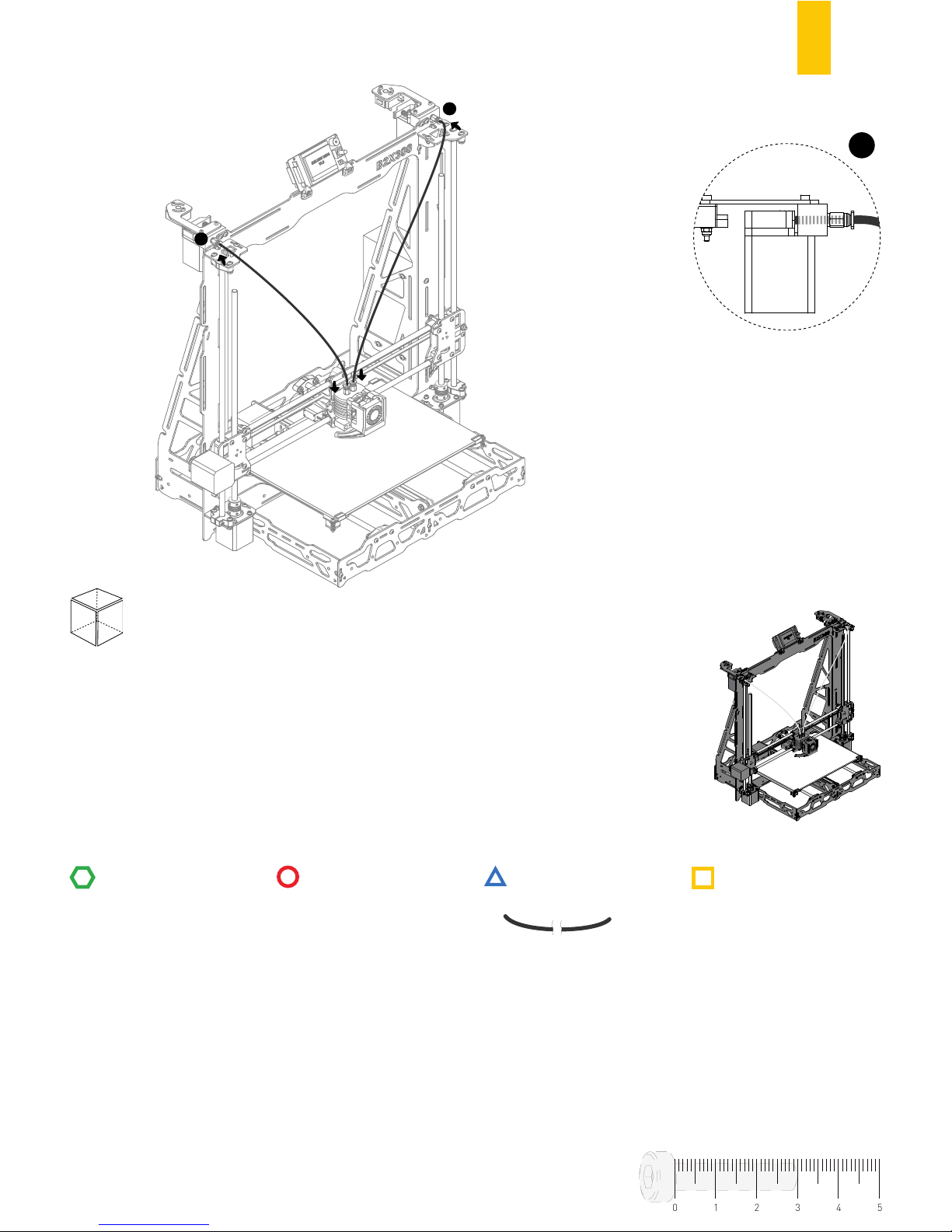
55
STRUCTURE
MECHANICS
ELECTRONICS
PRINTED PARTS
RULER
TOOLS
1
1
F.4
2
PTFE TUBE
01234
5
FRONT
1
Page 58
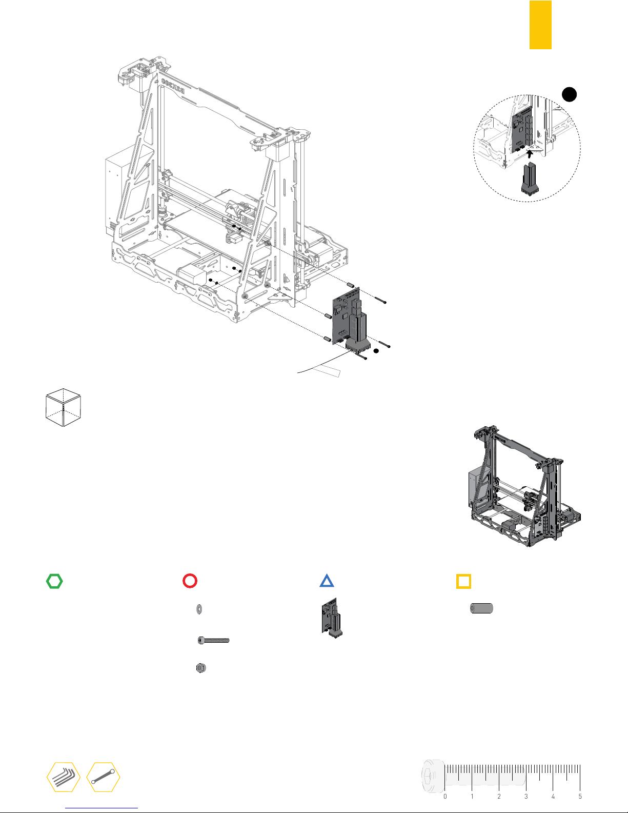
56
STRUCTURE
MECHANICS
ELECTRONICS
PRINTED PARTS
RULER
TOOLS
Δ
ELECTRONICS
1
BACK
F.5
MOTHER BOARD MKS GEN
PLAIN WASHER DIN125 M3
3
3
CYL. HEAD SCREW D912 M3X25
PCB SPACER
3
3
HEX. THIN NUT 1 DIN10511 M3
01234
5
1
Page 59
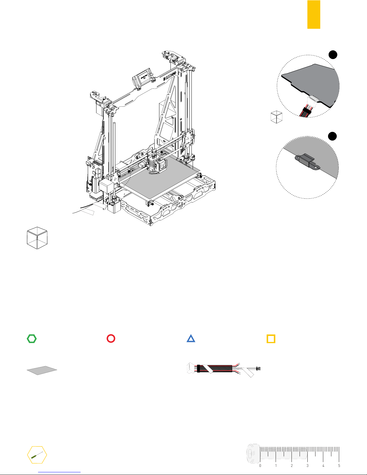
57
STRUCTURE
MECHANICS
ELECTRONICS
PRINTED PARTS
RULER
TOOLS
F.6
GLASS
Δ
H-BED
Δ
TH-BED
2
2
1
2
2
FRONT
2
Δ H-BED
Δ TH-BED
PCB HEATED BED CABLE
01234
5
1
BACK
Page 60
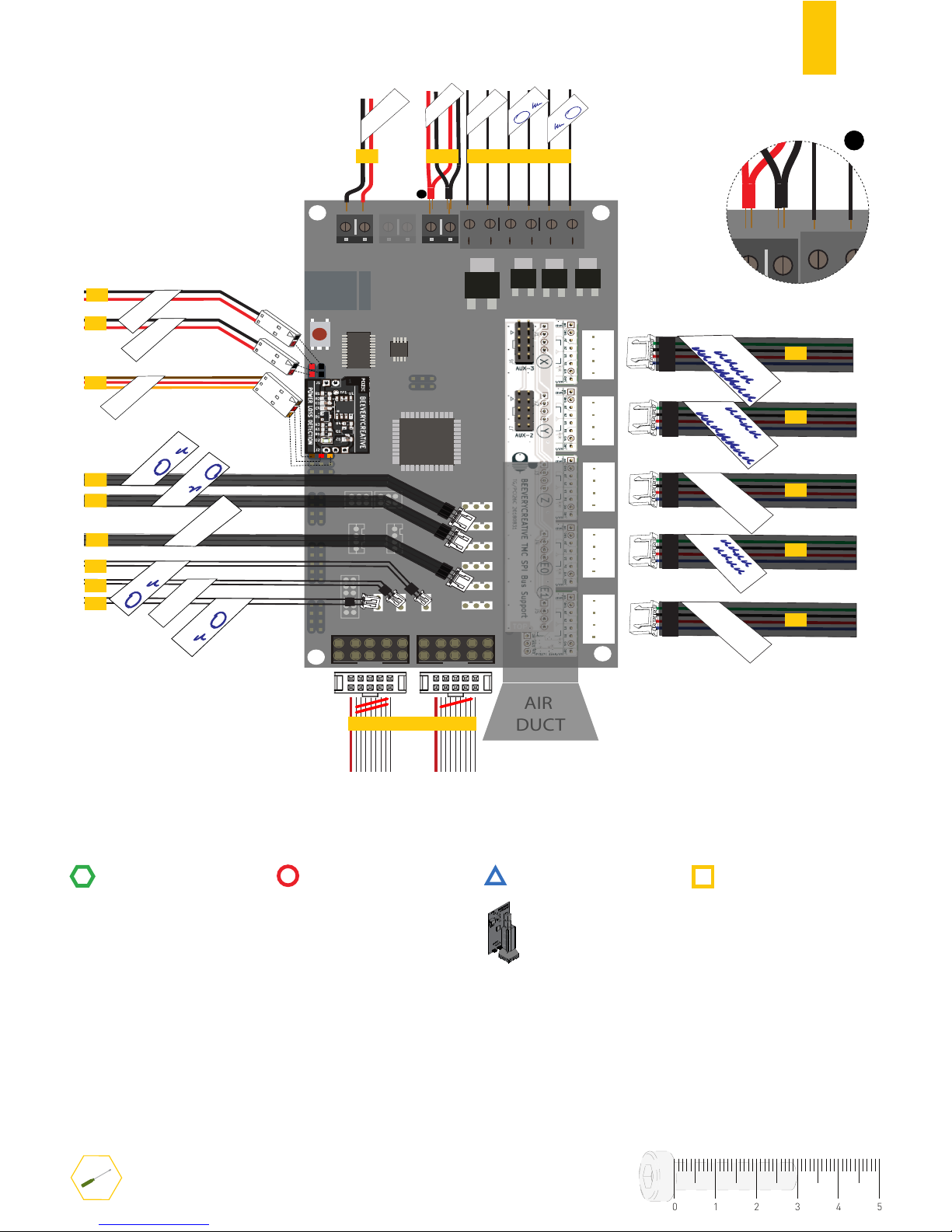
58
STRUCTURE
MECHANICS
ELECTRONICS
PRINTED PARTS
RULER
TOOLS
X-
X
Y
Z
E0
E1
Y+
Z-/J9
EXP1
BED
J16
E0
J21
E1
J14
EXP2
EXP1EXP2
Δ
X-AXIS
Δ
Z-AXIS
Δ EXTRUDER
E1
USB
Δ 24 VDC
Δ Heater
[E0] [E1]
Δ Blower
+H-BED-
+HE1-+HE0-
+FAN-
-12/24V+
r
Δ
CAL:SERVOS1
Δ H-BED
Δ Heater
[E0] [E1]
Δ
EXTRUDER SENSOR
[E0] [E1]
Δ
TH-BED
Δ
EXTRUDER SENSOR
[E0] [E1]
p.33
p.33
p.41
Δ
Y-AXIS
Δ
X-AXIS
Δ
EXTRUDER E0
Δ
Y-AXIS
Δ
X-AXIS
Δ
EXTRUDER E0
Δ
Y-AXIS
Δ
X-AXIS
Δ
EXTRUDER E0
Δ
ELECTRONICS
Δ
EXT - FAN
Δ FILAMENT
[E0] [E1]
Δ FILAMENT
[E0] [E1]
Δ
CAL:Z-/(J9)
AIR
DUCT
1
F.7
MOTHERBOARD MKS GEN V1.4
01234
5
p.57
p.54
p.31
p.16
p.48
p.46
p.53
p.57
p.52
p.45
p.16
1
+H-BED-
+FAN-
Attention to the labels in the motherboard
p.56
p.45
Page 61
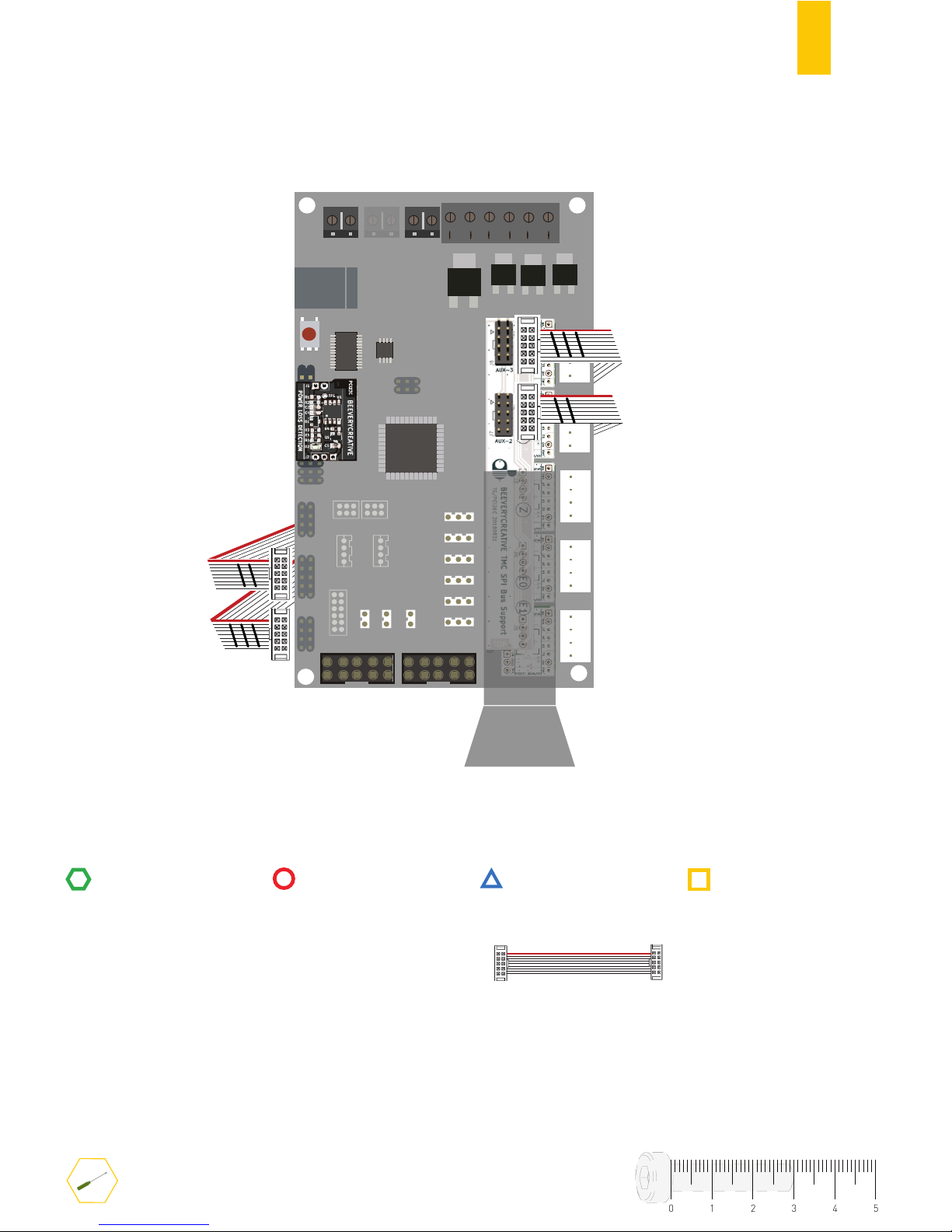
59
STRUCTURE
MECHANICS
ELECTRONICS
PRINTED PARTS
RULER
TOOLS
F.6
X-
X
Y
Z
E0
E1
Y+
Z-/J9
EXP1
BED
J16
E0
J21
E1
J14
EXP2
USB
+H-BED-
+HE1-+HE0-
+FAN-
-12/24V+
AIR DUCT
TRINAMIC DRIVERS FLAT CABLES
01234
5
2
These cables are pre-assembled
and go behind the motherboard
Page 62
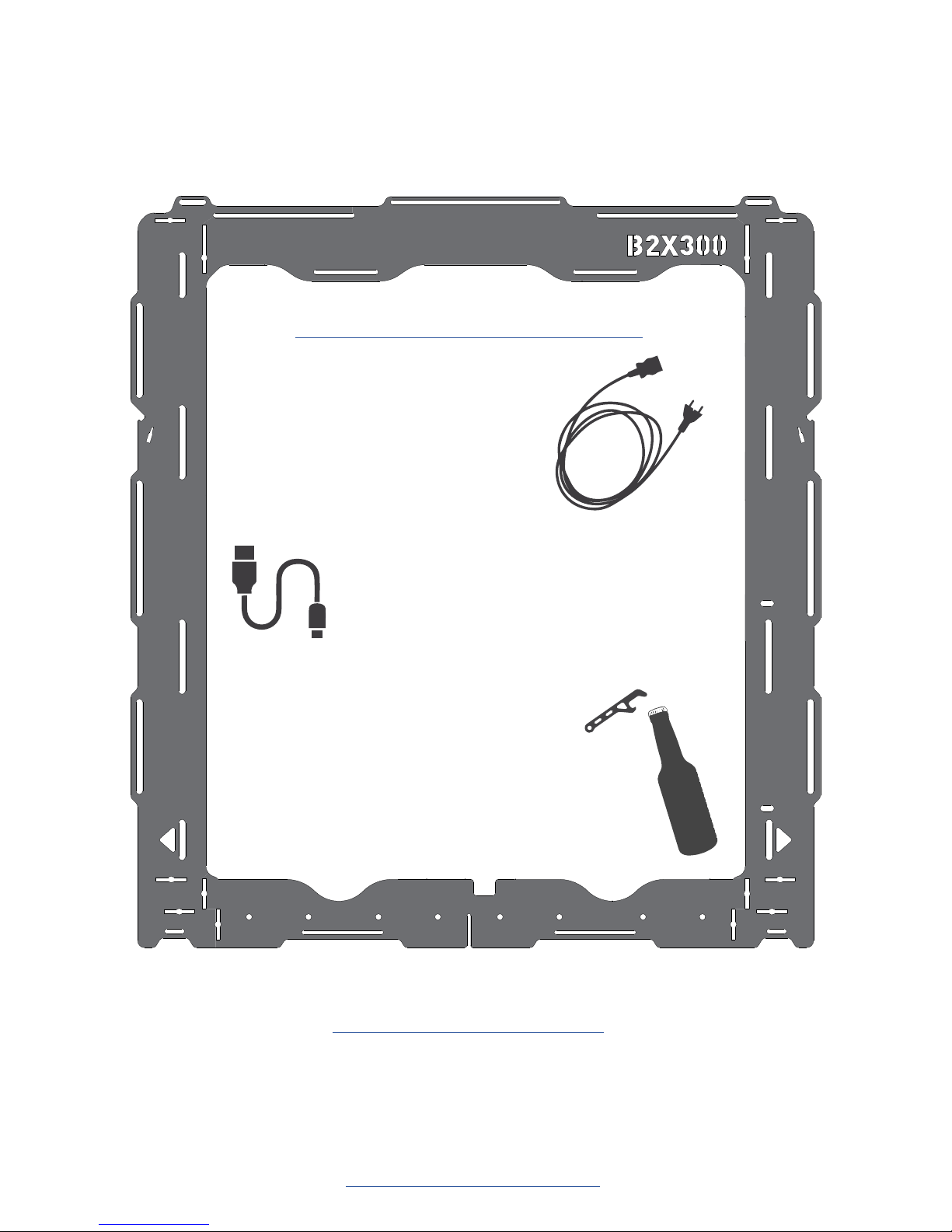
You may now connect your printer
to a power socket, with B2X300
power cable, and turn it on.
CONGRATULATIONS!
Your B2X300 3D printer is now assembled
Join us and share your experience here:
www.beeverycreative.com/forum
B2X300 is an open-source project.
Sources from this project are available here:
https://github.com/beeverycreative
HAPPY 3D PRINTING!
You may use the USB
cable provided with the kit to communicate
with the computer.
Do you have any structure frame spare part?
You have completed the assembly of your
B2X300 3D printer.
Here is a little gift to help you celebrate.
Hope you enjoy it!
Final step > Download the User Manual here:
www.beeverycreative.com/manuals-tutorials
Page 63

© 2018 BEEVERYCREATIVE
www.beeverycreative.com
All rights reserved.
www.facebook.com/beeverycreative
www.instagram.com/beeverycreative
www.linkedin.com/company/beeverycreative
www.twitter.com/beeverycreative
www.youtube.com/user/BEEVERYCREATIVE
www.google.com/+beeverycreative
 Loading...