

Page 1
BEETLE /iPRO
Modular POS System
User Guide
Edi ti on September 2005
Page 2

Co py right© Win cor Nix dorf In ter na tio nal GmbH, 2005
The re pro duc ti on, trans mis si on or use of this do cu ment or its con tents is not
per mit ted wit hout ex press aut ho ri ty.
Of fen ders will be li ab le for da ma ges.
All rights, in clu ding rights crea ted by pa tent grant or re gi stra ti on of a uti li ty mo del or
de sign, are re ser ved.
De li very sub ject to avai la bi li ty; tech ni cal mo di fi ca tions pos si ble.
Li nux™ is a re gis te red tra de mark of Li nus Tor valds
Pen ti um™ is a re gis te red tra de mark of the In tel Cor po ra ti on
MS-DOS™, Wind ows 95™, Wind ows 98™, Wind ows NT™, Wind ows ME™,
Wind ows2000™and Wind ows XP™ are re gis te red tra de marks of the Mi cro soft
Cor po ra ti on
Page 3

Contents
Ma nu fac tu rers Cer ti fi ca ti on................................................1
Tes ted Sa fe ty..............................................................................................1
FCC-Class A De cla ra ti on............................................................................1
Im por tant No tes ..........................................................................................2
Note on the la ser ........................................................................................3
In tro duc ti on..........................................................................4
About this Ma nu al .......................................................................................4
Care of the BEET LE /iPRO.........................................................................5
Re cy cling the BEET LE /iPRO .....................................................................6
War ran ty .....................................................................................................7
Over view...............................................................................8
BEET LE /iPRO Pe ri phe rals ........................................................................9
BEET LE /iPRO in a Net work.....................................................................10
Be fo re swit ching on the Sys tem ................................................................11
Un pa cking and che cking the Sys tem ..................................................11
Set ting up the De vi ce ..........................................................................11
Cab ling of the BEET LE /iPRO .............................................................11
Con nec ting to the Mains Vol ta ge.........................................................12
Dis con nec ting Ca bles..........................................................................12
In stal la ti on of the BEET LE /iPRO .............................................................13
Ver ti cal Moun ting.................................................................................13
Ho ri zon tal Moun ting ...........................................................................14
Moun ting the Ca ble Co ver...................................................................14
Ba sic Set tings .....................................................................................15
Ad ju sting the Loud spea ker ..................................................................15
Light Emit ting Di ode (LED)..................................................................15
Con nec ting Pe ri phe rals.............................................................................15
Key bo ard (KYBD)................................................................................16
Scan ners and Sca les (COM1 - COM4*)..............................................16
Cus to mer Dis play (COM2* or COM4*) ................................................17
Cas hier Dis play (COM3*) ....................................................................17
Mo ni tor ...............................................................................................17
TFT - LCD Dis play ..............................................................................18
Con nec ting Stan dard PC Pe ri phe rals (COM1) ....................................18
Net work ...............................................................................................19
Mo du lar Prin ters ..................................................................................19
USB (Uni ver sal Se ri al Bus) .................................................................20
Page 4

BEET LE /iPRO - the Com po nents ....................................21
Over view...................................................................................................21
Flop py Disk Dri ve (op tio nal) ......................................................................23
Ge ne ral ...............................................................................................23
Re mo ving a disk..................................................................................23
CD-ROM/DVD Dri ve (op tio nal) .................................................................24
Ge ne ral ...............................................................................................24
Ope ra ting the Dri ve .............................................................................24
No tes...................................................................................................25
Po wer Supp ly Unit (200 W) .......................................................................25
Po wer Supp ly Unit (272 W) .......................................................................26
Con fi gu ra ti on Va riants......................................................27
Sub mo du les for the CPU ..........................................................................27
LAN Con trol ler 10/100 MBit.................................................................27
CRT- or TFT-Adap ter ..........................................................................27
In stal ling a Sub mo du le .............................................................................27
Chan ge of the CD-ROM/DVD Dri ve..........................................................29
Chan ge of the Hard Disk Dri ve .................................................................31
In stal ling an Ex pan si on Card ....................................................................33
Re tail Soft wa re...................................................................36
Win cor Nix dorf Sto re So lu tions .................................................................36
Plat forms and Pro ducts.............................................................................37
Tra ding Post ........................................................................................37
TP.net .................................................................................................38
TPLi nux ...............................................................................................38
Tech no lo gy eva lua ti on ........................................................................38
Star ting up the Sys tem .....................................................39
Start and Ru nup Be ha vi our.......................................................................39
Ap pen dix ............................................................................41
Tech ni cal Data for the BEET LE /iPRO......................................................41
Back Pa nel of the BEET LE /iPRO ............................................................42
Glos sa ry....................................................................................................43
Ab bre via tions ............................................................................................45
Page 5

Manufacturers Certification
The device complies with the requirements of the EEC
directive 89/336/EEC with regard to ‘Electromagnetic
compatibility" and 73/23/EEC “Low Voltage Directive”.
Therefore, you will find the CE mark on the device or packaging.
Tested Safety
The POS sys tem has been pro vi ded with the sym bol for
“Tes ted Sa fe ty”.
In ad di ti on, the BEET LE has re cei ved the UL sym bol and cUL
sym bol.
FCC-Class A Declaration
This equipment has been tested and found to comply with the limits for a
Class A digital device, pursuant to part 15 of the FCC Rules. These limits
are designed to provide reasonable protection against harmful inter-ference
when the equipment is operated in a commercial environment. This
equipment generates, uses, and can radiate radio frequency energy and, if
not installed and used in accordance with the instruction manual, may cause
harmful interference to radio communications.
Operation of this equipment in a residential area is likely to cause harmful
interference in which case the user will be required to correct the
interference at his own expense. Modifications not authorized by the
manufacturer may void users authority to operate this device. This class A
digital apparatus complies with Canadian ICES-003.
Cet appareil numerique de la classe A est conforme à la norme NMB-003
du Canada.
1
TESTED SAFETY
geprüftegeprüfte
SicherheitSicherheit
Page 6

Important Notes
The modular POS system BEETLE /iPRO conforms to the current safety
standards for data processing equipment.
n
If this device is taken from a cold environment into the operating room,
moisture condensation may form. The device must be absolutely dry
before being put into service; an acclimatization period of at least two
hours must therefore be observed.
n
This device is equipped with a safety-tested power cable and may be
connected only to a prescribed grounded-contact power socket.
n
When setting up the device, ensure that the power socket on the device
and the grounded-contact power socket are easily accessible.
n
To disconnect the device from the supply voltage completely, switch off
the device and disconnect the power plug.
n
Keep free the ventilation slots in front and back of the equipment to
ensure an ordinary temperature inside.
n
Ensure that no foreign objects (e.g. office clips) find their way into the
device, as this may lead to electric shocks or short-circuits.
n
Never plug in or unplug data communication lines during thunderstorms.
n
Protect devices from vibrations, dust, moisture and heat.
n
Always dispose of used parts, such as batteries, in an environmentally
safe manner.
The lithium battery must be disposed of in accordance with local regulations
for special waste. The lithium battery must be replaced by authorized
personnel only. Incorrect replacement may lead to the danger of explosion.
n
In emergencies (e.g. damaged housing or damaged power cable,
penetration by liquids or foreign bodies) the device must be switched off
immediately, the power plug disconnected and the Customer Service of
Wincor Nixdorf or your reseller must be notified.
n
The device may only be repaired by authorized qualified personnel.
Unauthorized opening of the device and inexpertly carried-out repairs may
IMPORTANT NOTES
2
Page 7

not only seriously jeopardize the safety of the user, but also cancel all
warranty and liability agreements.
n
Your BEETLE POS system is the result of modern technical innovation.
So please see for according structural and technical surroundings to
guarantee a faultless and efficient work of your BEETLE.
Therefore, you should connect your BEETLE or other IT-devices only to
power supply systems with separately guided protective earth conductors
(PE). This kind of electricity system is known as TN-S network. Do not
use PEN conductors!
Please also observe the recommendations of the norm DIN VDE 0100,
Part 540, Appendix C2 as well as EN50174-2, §5.4.3. Thus you can help
to avoid possible malfunctions.
Note on the laser
lf your device is equipped with a CD ROM/DVD drive, the following condition
applies:
The CD ROM drive contains a light-emitting diode (LED), classified
according to IEC 825-1:1993:LASER CLASS 1; it must not be opened.
3
NOTE ON THE LASER
Page 8

Introduction
The BEETLE /iPRO is the powerful and economical basis for your POS
system.
The BEETLE conforms to the PC industry standard. Powerful processors
ensure a quick processing of all operations. You can connect a variety of
different peripheral devices to your BEETLE and even the choice of the
software is not limited to a certain product.
Optionally, the BEETLE /iPRO can be equipped with a floppy disk drive,
a CD-ROM drive, a DVD drive or a 2nd hard disk.
This provides you with a considerable degree of flexibility when arranging
the configuration of your POS system.
The BEETLE can also be connected to a network once an appropriate
network card has been installed.
Whatever configuration you need: Wincor Nixdorf offers the right solution.
So, whenever you want to expand your BEETLE /iPRO, please contact your
Wincor Nixdorf branch office.
About this Manual
This documentation is intended to help you work with the POS system and
to serve as a reference work. The detailed table of contents helps you find
the desired information quickly and easily.
The first section after the introduction describes
n
ever ything you need to do be fo re swit ching on the POS sys tem. There are
details how to mount the system and how to con nect pe ri phe rals to the
BEETLE /iPRO.
The second section contains
n
a brief over view of the com po nents of your BEET LE POS sys tem. Here,
you will also find a de tai led des crip ti on of re cur ring ac tions, for ex am ple,
how to use the disks.
The third selection describes
n
the possible configuration variants of your BEETLE /iPRO.
ABOUT THIS MANUAL
4
Page 9

The fourth section provides
n
a general overview of the Wincor Nixdorf Retail Software.
Section five
n
explains the start and runup behaviour of the BEETLE /iPRO.
The Appendix
n
con tains the most im por tant tech ni cal data, a glos sa ry and a list of
ab bre via tions.
Notes in the manual are marked by this symbol.
This symbol is used for warnings.
The type and scope of application programs depend on the customer’s own
selection; therefore software will not be discussed further in this manual.
Separate manuals are included in the scope of the connectable peripherals.
For this reason, a more detailed description of these devices will not be
provided here. For more information, see the relevant manuals.
Care of the BEETLE /iPRO
Clean your BEETLE /iPRO at regular intervals with a suitable plastic-surface
cleaner. Make sure that the power plug is disconnected, connector cables
are unplugged and that no liquid finds its way into the device (read also the
chapters "Safety Instructions" and "Warranty").
5
CARE OF THE BEETLE /IPRO
Page 10

Recycling the BEETLE /iPRO
En vi ron men tal pro tec ti on does not be gin when the time
has come to dis po se of the BEET LE; it be gins with the
ma nu fac tu rer. This pro duct was de sig ned ac cor ding to
our in ter nal norm “En vi ron men tal cons ci ous pro duct
de sign and de ve lop ment”.
The modular BEETLE /iPRO system is manufactured without the use of
CFCs and CCHS and is produced mainly from reusable components and
materials.
The processed plastics can, for the most part, be recycled. Even the
precious metals can be recovered, thus saving energy and costly raw
materials.
Please do not stick labels onto plastic case parts. This would help us to
re-use components and material.
You can protect our environment by only switching on your equipment when
it is actually needed. If possible, even avoid the stand-by-mode as this
wastes energy, too. Also switch your equipment off when you take a longer
break or finish your work.
At this time, there are still some parts that are not reusable. Wincor Nixdorf
International GmbH guarantees the environmentally safe disposal of these
parts in a Recycling Center, which is certified pursuant to ISO 9001 and ISO
14001.
So don’t discard your BEETLE /iPRO system on the garbage when it has
served its time, but take advantage of the environmentally smart, up-to-date
recycling methods!
Plea se con tact your com pe tent branch or the Re cy cling Cen ter Pa der born
(for Eu ro pe an coun tries) for in for ma ti on on how to re turn and re-use de vi ces
and dis po sa ble ma ter ials un der the following mail address:
Email: info@win cor-nix dorf.com
or on the internet.
We look for ward to your mail.
RECYCLING THE BEETLE /IPRO
6
Page 11

Warranty
Win cor Nix dorf gua ran tees ge ne ral ly a war ran ty en ga ge ment for 12 months
be gin ning with the date of de li very. This war ran ty en ga ge ment co vers all
da ma ges which oc cur de spi te a nor mal use of the pro duct.
Da ma ges be cau se of
n
im pro per or in suf fi cient main ten an ce,
n
im pro per use of the pro duct or un aut ho ri zed mo di fi ca tions of the pro duct,
n
ina de qua te lo ca ti on or sur roun dings
will not be co ver ed by the war ran ty.
For furt her in for ma ti on of the sti pu la ti on look at your con tract.
All parts of the pro duct which are sub ject to wear and tear are not in clu ded
in the war ran ty en ga ge ment.
Plea se or der spa re parts at the Win cor Nix dorf cus to mer ser vi ce.
7
WARRANTY
Page 12

Overview
You can connect a variety of peripherals to your modular POS system
BEETLE /iPRO and thus implement a wide range of expansion stages. You
can connect a two or four-line alphanumeric customer display and a four line
cashier display. Alternatively you can connect flat screens, use various
types of scanners such as distance, touch or stationary scanners, use
scales and scanner scales (please take into account the official certification
regulations), connect various printers, use POS keyboards with or without a
swipecard reader, connect a monitor, install the POS workplace SNIkey,
integrate the BEETLE /iPRO in a network after installing a LAN board and
upgrade the BEETLE /iPRO, since it can accommodate two PCI extension
cards.
This means that the BEETLE /iPRO can meet your requirements at all
times, without having to exchange the complete system for a new one, thus
saving you time and money.
The following illustrations show you how your modular POS system can
grow - from a scanner to integration into a network.
OVERVIEW
8
Page 13
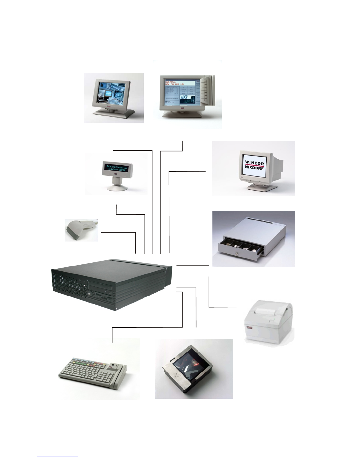
BEET LE /iPRO Pe ri phe rals
9
BEET LE /IPRO PE RI PHE RALS
Two and four li nes cus to mer
display
LCD Screen
SNIkey
Handscanner
CRT Monitor
Cashdrawer (con nec table via
prin ter )
Printer
Sta tio na ry Scanner
Keyboard
Page 14
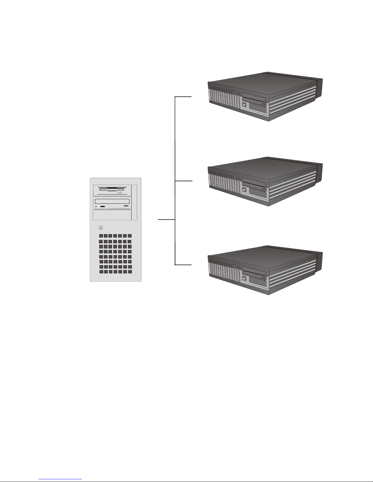
BEET LE /iPRO in a Net work
BEET LE /IPRO IN A NET WORK
10
Ethernet 10/100 Base T
Server
Page 15

Before switching on the System
Un pac king and chec king the System
Unpack the parts and check to see whether the delivery matches the
information on the delivery note.
The carton contains the basic unit and a country-specific accessories kit.
Some ordered composition may be installed.
If damage has occurred during shipping or if the package contents do not
match the delivery note, promptly inform your Wincor Nixdorf sales outlet.
Trans port the de vi ce only in its ori gi nal pa cka ging (to pro tect it against
im pact and shock).
Set ting up the De vi ce
Set up the BEETLE /iPRO POS system where it will not be exposed to
extreme environmental conditions. Protect the device from vibrations, dust,
moisture, heat and strong magnetic fields.
Make sure that the ven ti la ti on slots in the front and in the back of the
BEETLE /iPRO sys tem are not ob struc ted in or der to en su re that the de vi ce
has suf fi cient ven ti la ti on.
You can put a keyboard in a desistance from 50 mm before the equipment.
Cab ling of the BEET LE /iPRO
Follow the steps below in the order given when installing devices:
n
The cable cover must be removed, if present.
n
Plug one end of the power cable into the socket of the BEETLE /iPRO.
n
Plug in and secure the data cable.
n
Plug the other end of the power cable into the main power supply.
Al ways make sure that all power plugs from the grounded-contact power
sockets are unplugged.
11
BEFORE SWITCHING ON THE SYSTEM
Page 16
Con nec ting to the Mains Voltage
If it is a 200 W power supply make sure that the correct particular voltage
(115/230V) is adjusted at the back side of the BEETLE (see chapter power
supply unit).
A wrong adjustment of the power output may cause the destruction of the
power supply.
All devices belonging to the modular BEETLE /iPRO system that have a
separate power cable must be connected to the same electric circuit.
n
Make sure that all data cables on the system unit and peripherals are
connected correctly.
n
You can now push the ON button at the front of the box.
Dis con nec ting Ca bles
Never unplug a cable by pulling on the cable itself; always take hold of the
actual plug. Follow the procedure below when disconnecting cables:
n
Turn off the button on the front of the BEETLE /iPRO and unplug the
power plugs from the grounded-contact power sockets.
n
Remove the cable cover.
n
Unplug all data communication cables from the sockets of the data
networks.
n
Unplug all power plugs from the grounded-contact power sockets.
n
Unplug all cables from the devices.
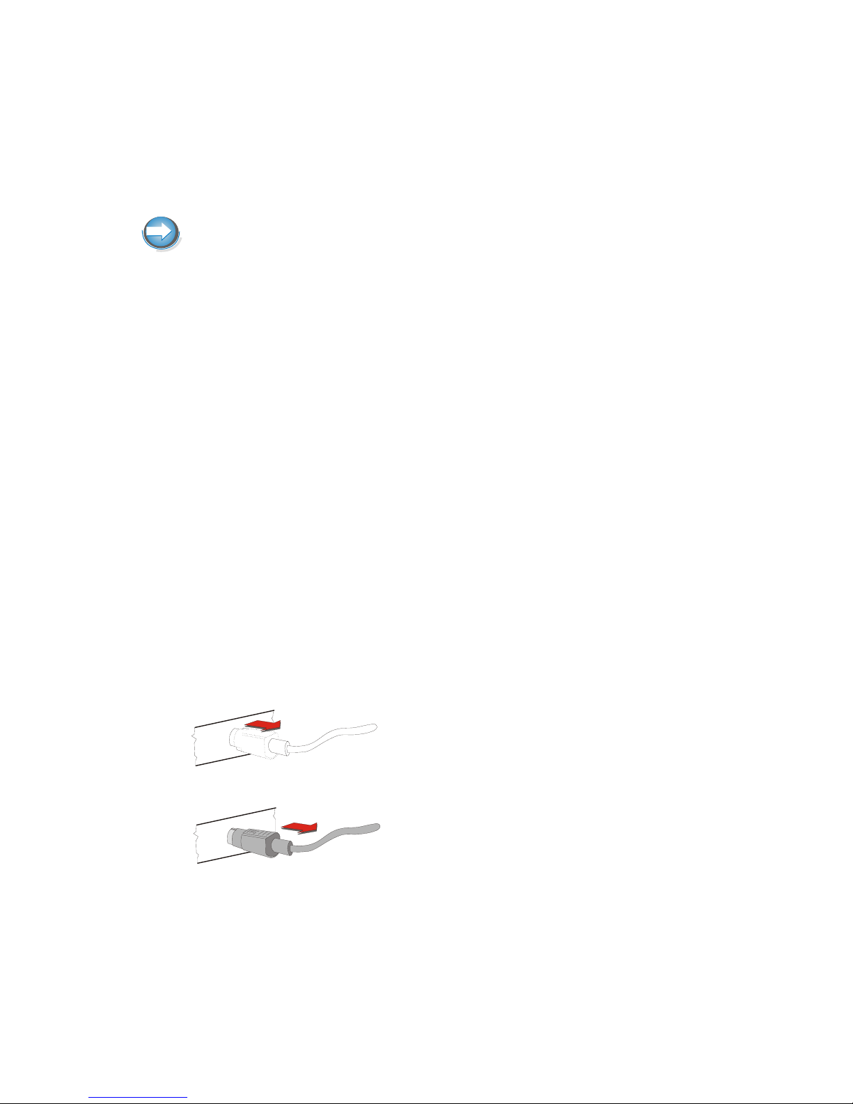
With MINI-DIN plugs, the plug remains inserted
until released.
Pull the plastic covering from the connecting
socket with your thumb. The lock is released.
The metal of the plug is visible.
BEFORE SWITCHING ON THE SYSTEM
12
Page 17
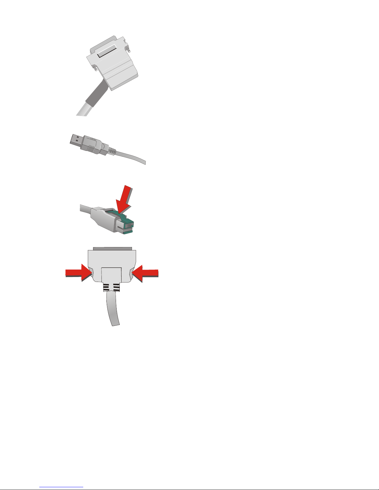
The D-sub type connector or CRT (VGA)
connector is used for parallel or serial
interfaces. Release the connector by loosening
the two screws.
Take hold of the USB connector housing and
release the connection.
Loosen the plug of the USB powered connector
by pressing the metal latch.
Release the TFT connector py pressing the
latches on the left and right inwards.
Installation of the BEETLE /iPRO
Ver ti cal Moun ting
The BEETLE /iPRO is specified for a horizontal mounting. Observe the
following if the system still is to be mounted vertically:
13
INSTALLATION OF THE BEETLE /IPRO
Page 18
n
Do not block the rear and the front side of the sys tem to en su re a
suf fi cient ven ti la ti on.
Ho ri zon tal Moun ting
n
To ensure sufficient ventilation a free convection must be provided.
Therefore the rear and front side of the system must be completely free
so nothing blocks the ventilation.
Moun ting the Ca ble Co ver
The scope of supply of your BEETLE /iPRO includes a cable cover.
Two slots are located left and right at the back side of the BEETLE /iPRO.
You put the hitches of the cable cover (see figure) into the slots of the
BEETLE /iPRO.
INSTALLATION OF THE BEETLE /IPRO
14
Hitch
Note
The back side of a de vi ce with a moun ted ca ble co ver must not blo cked.
Page 19
Ba sic Set tings
Ex works, the BEETLE /iPRO is configured to your order. Your configuration
must be subsequently adapted to support supplementary devices such as
scanners. For more information, contact the Wincor Nixdorf branch office
responsible for your area.
Ad ju sting the Loud spea ker
You can set the volume as desired in the menu in the BIOS Setup (see
manual “BEETLE POS-/Motherboard”).
Light Emit ting Diode (LED)
You will find the LEDs at the front side of the BEETLE /iPRO. The right LED
POWER (green) lights when the BEETLE /iPRO is switched on. The left
LED HDD (yellow) lights up while the hard disk is being accessed.
Connecting Peripherals
The peripherals mentioned here are available as options and are not part of
the basic configuration. A separate manual is provided for each of the
connectable components. For more detailed information, please consult the
relevant documentation.
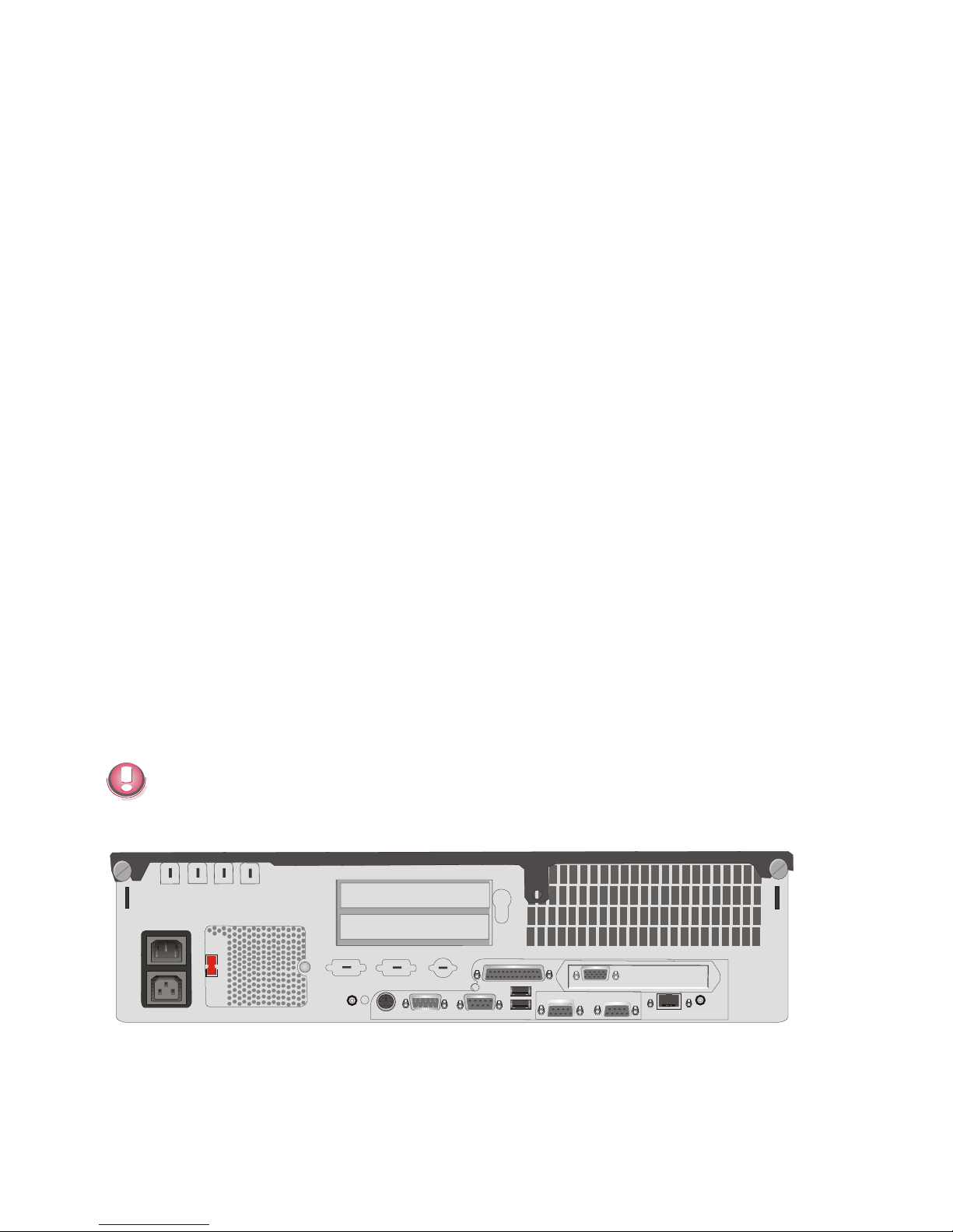
The figure shows the back panel of the BEETLE /iPRO with the locations of
the connecting sockets and connecting plugs.
Connecting peripherals with the system switched on is not allowed. USB
peripherals are an exception. Only connect devices equipped with a
shielded cable to the standard USB interface.
Back pa nel of the BEET LE /iPRO (Stan dard, 200W po wer supp ly unit)
15
CONNECTING PERIPHERALS
COM1 COM2
COM4
CRT
LPT1
COM3
USB
SPK
LAN
MIC
KYBD
230
100-120 V / ~ 2A max
200-240 V / ~ 1A max
Page 20
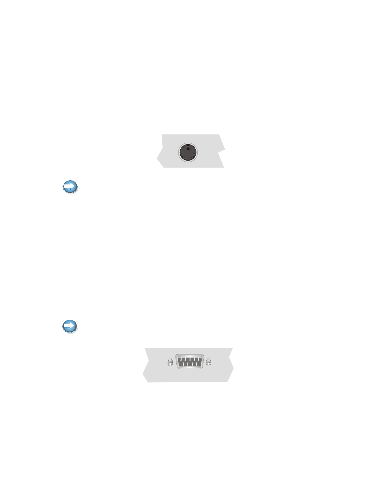
Key bo ard (KYBD)
The BEETLE /iPRO has a 6-pin mini-DIN jack for connecting a keyboard.
Make sure that the connector is plugged firmly into the socket to prevent
malfunctioning.
Power is supplied to the keyboard via this socket. If you wish to connect a
standard PC keyboard with DIN connector, you must use a special adapter
cable, obtainable from the Wincor Nixdorf branch office responsible for your
area.
In addition to the keyboard it is possible to connect a mouse via y-adapter.
When removing cables with locks, please grip the cable at the connector
housing.
Scan ners and Sca les (COM1 - COM4*)
Depending on the systems configuration, scanners without an independent
power supply are connected to the COM2*, COM3* or COM4* serial
interface (standard setting COM3*). Connect scales with their own power
supply to the COM1 interface. COM1 is designed as a 9-pin D-sub plug,
where as COM2* - COM4* are 9-pin D-sub jacks.
Make sure that the scanner connector is plugged securely into the socket to
prevent possible malfunctioning.
If scales which are not supplied by Wincor Nixdorf are connected to the
BEETLE /iPRO, you must obtain a licence for the driver software.
CONNECTING PERIPHERALS
16
Page 21
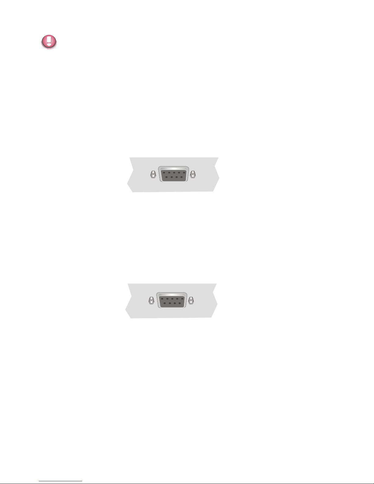
The COM2* interface is used internally when a screen (BA7x) with
Touchscreen function is connected. For settings see the BIOS setup.
In this case the interface is not available for other peripheries.
Cus to mer Dis play (COM2* or COM4*)
With the BEETLE /iPRO, and depending on the system´s configuration, the
customer display is connected to either the COM2* or COM4* serial
interface. The interface connection is a 9-pin D-sub jack.
Power is supplied via this jack.
Make sure that the connector for the customer display is screwed firmly to
the socket to prevent possible malfunctioning.
Cas hier Dis play (COM3*)
Connect the cashier display to the serial interface COM3*. This port is a
9-pin D-sub jack.
Make sure that the connector for the cashier display is screwed firmly to the
socket to prevent possible malfunctioning.
Mo ni tor
If a CRT adapter is installed, you can connect a monitor to the
BEETLE /iPRO via the 15-pin D-sub jack on the CRT adapter.
17
CONNECTING PERIPHERALS
Page 22
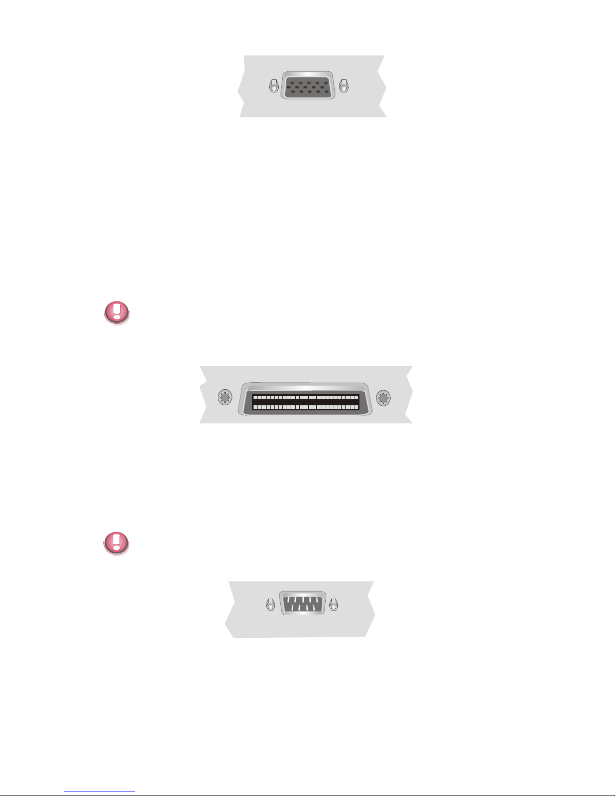
A LCD screen can be connected alternatively if a TFT adapter is installed.
TFT - LCD Dis play
If a TFT adapter is installed you can connect a Panellink-TFT to the
BEETLE /iPRO. Connect the 40-pin data cable of the LCD to the system.
The signals for the touch screen function and the power supply is also made
via this cable. To implement the touch screen functionality for the COM2*
interface you have to change some system settings (see also chapter
Configuration variants).
The COM2* interface is without effect if the onboard TFT adapter with touch
screen function is installed. In this case the interface is not available for
other peripheries.
Con nec ting Stan dard PC Pe ri phe rals (COM1)
You can connect supplementary standard peripherals to the BEETLE /iPRO
via the COM1 serial interface.
Make sure that all supplementary devices have been tested for RFI
suppression pursuant to the legal requirements of your country.
CONNECTING PERIPHERALS
18
Page 23
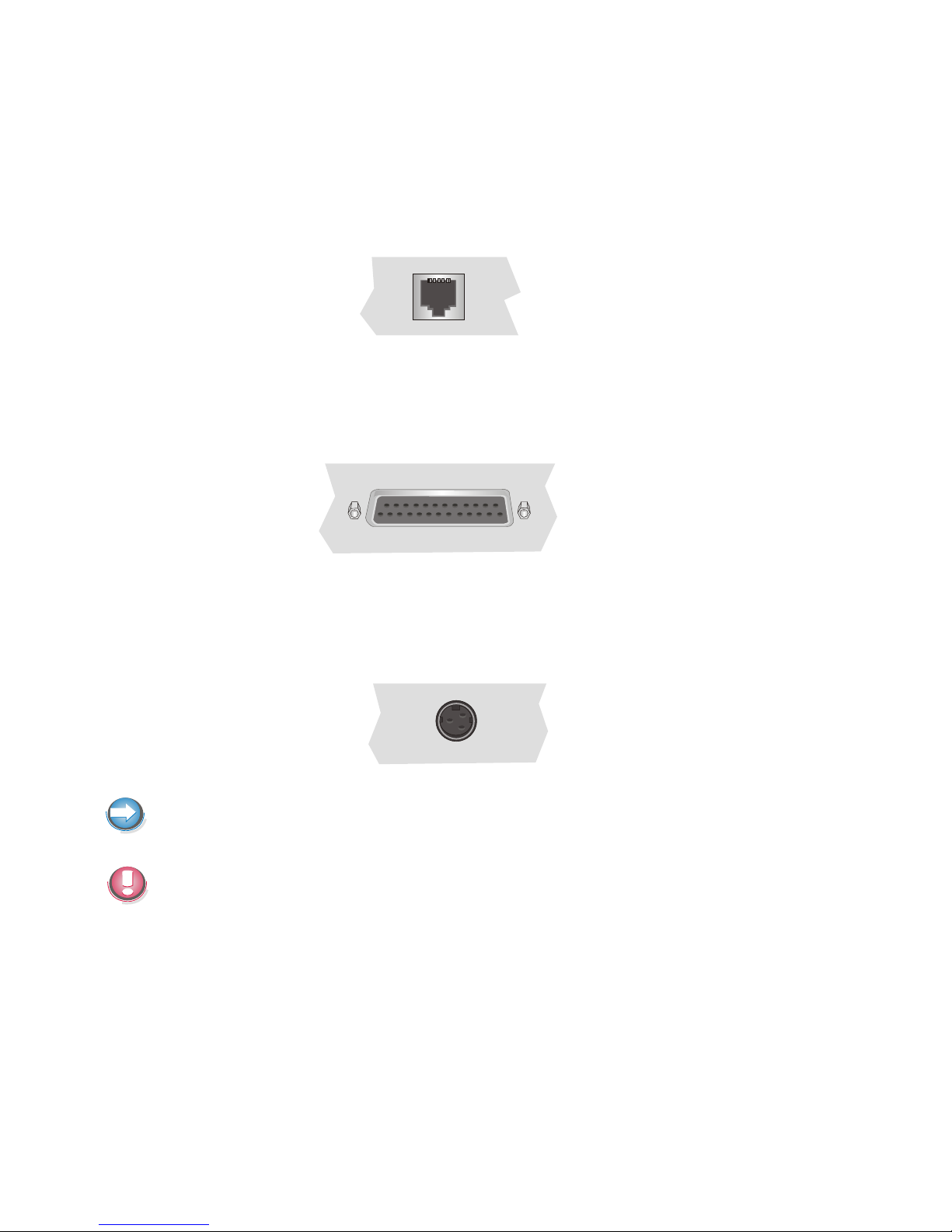
Net work
If a network board is installed, the system can be connected to a network
(LAN) from the POS terminal back panel. If a LAN board is not installed, this
location on the back panel is closed by a dummy cover (see also chapter
Configuration Variants).
Mo du lar Prin ters
The standard parallel interface LPT1 is intended for connecting a printer.
Appropriate POS printers can also be connected via the low-voltage jack
24V on the power supply unit (272 W), max. 3A. A connecting cable with a
HOSIDEN plug is required for this.
Connect only cables to the 24V connector which are marked with DP-1 or
DP-2.
Do not connect the HOSIDEN plug when the system is turned on, this can
lead to an automatical reboot of the system.
19
CONNECTING PERIPHERALS
Page 24
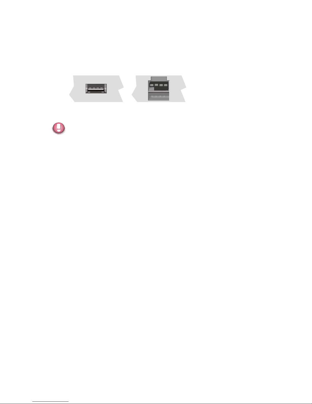
USB (Uni ver sal Se ri al Bus)
You can connect several USB peripheral devices to the USB or powered
USB interface (12V).
12V
Only connect devices equipped with a shielded cable to the USB-interface.
CONNECTING PERIPHERALS
20
Page 25
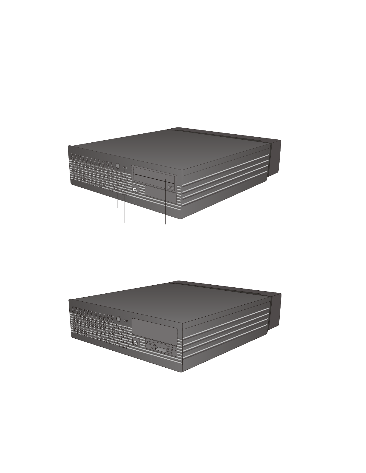
BEETLE /iPRO - the Components
Overview
The following figures show the outside of the BEETLE /iPRO.
21
OVERVIEW
LEDs
ON/OFF But ton
CD-ROM/DVD Dri ve (op tio nal)
USB
Flop py Disk Dri ve (op tio nal)
Page 26
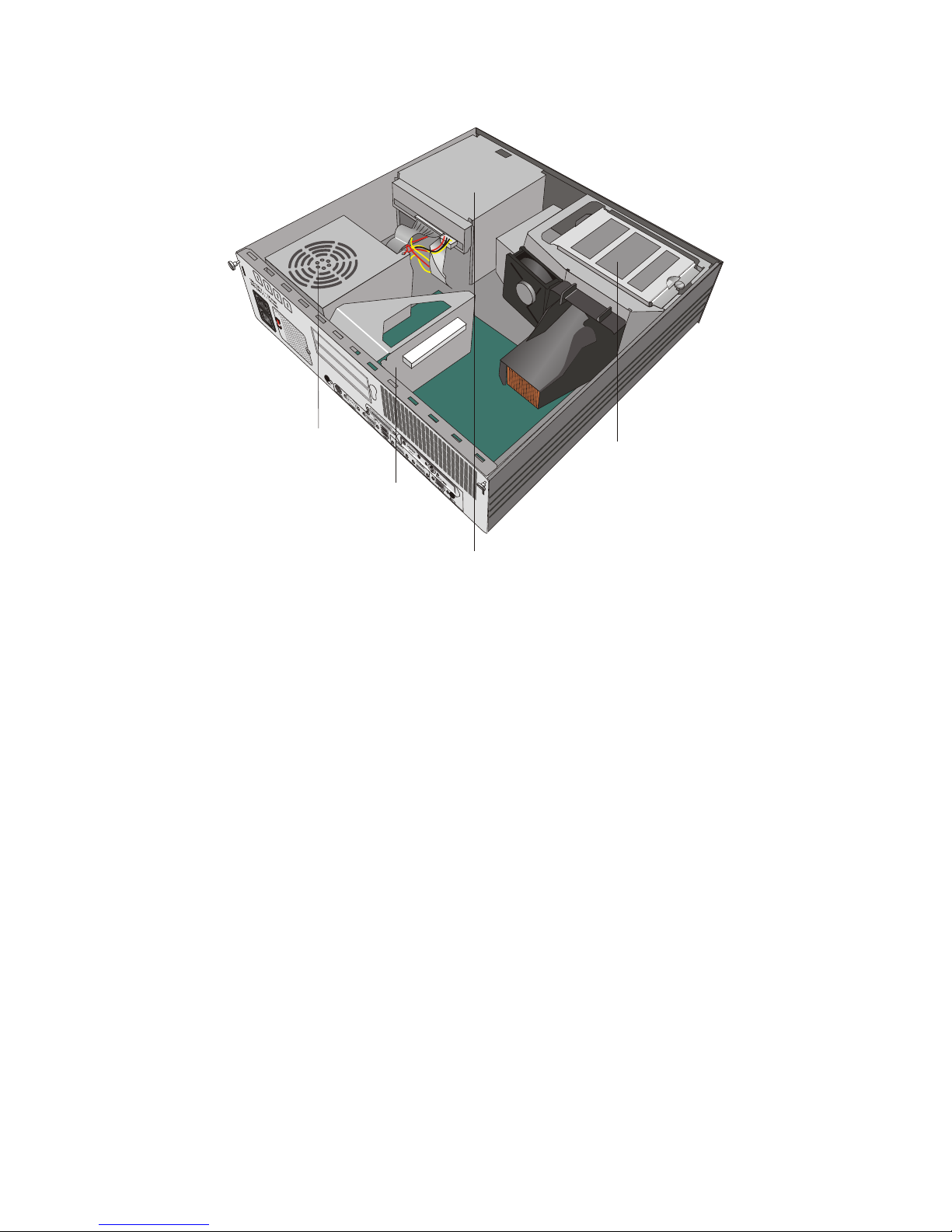
The figure below shows the inside of the BEETLE /iPRO.
OVERVIEW
22
Hard Disk
Po wer Supp ly Unit
Flop py Disk Dri ve/
CD-ROM/DVD Dri ve
Ri ser Board
Page 27
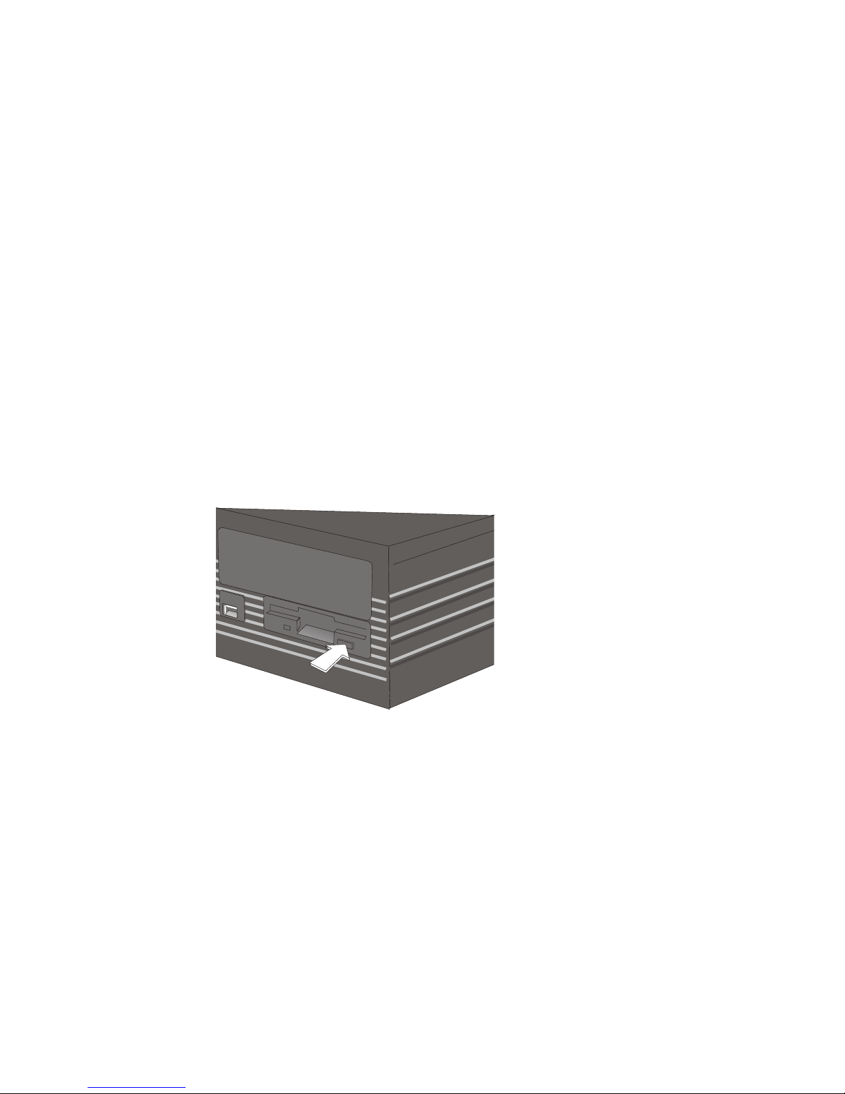
Floppy Disk Drive (optional)
Ge ne ral
The BEETLE /iPRO may be equipped with a floppy disk drive for 3.5" disks.
The LED at the drive lights up whenever the system accesses the drive.
The disks can be used for a variety of applications, such as:
n
Loading programs
n
Saving data (e.g. daily sales figures)
n
Access control (electronic key)
The disk can be write protected to protect your data from accidentally being
overwritten. The slide is located at the bottom left of the diskette.
Re mo ving a disk
Press the ejection button next to the drive slot. You can now remove the
disk.
Never remove the disk while the drive is being accessed, i.e. when the LED
indicator for the drive is illuminated. Otherwise, you could damage the drive
and the disk.
23
FLOPPY DISK DRIVE (OPTIONAL)
Page 28
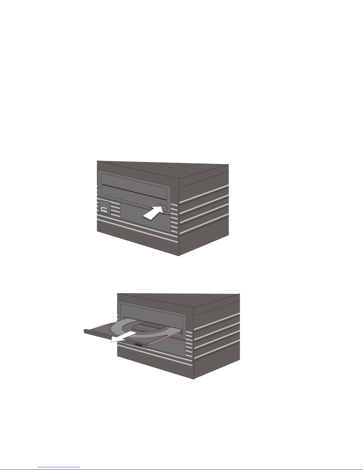
CD-ROM/DVD Drive (optional)
Ge ne ral
Optionally the BEETLE /iPRO can be equipped with a CD-ROM/DVD drive.
The LED at the drive lights up whenever the system accesses the drive.
Ope ra ting the Dri ve
To start the drive, follow the procedure below:
n
Turn on the power supply.
n
Press the ejection button.
n
The drawer is ejected from the drive.
CD-ROM/DVD DRIVE (OPTIONAL)
24
Page 29
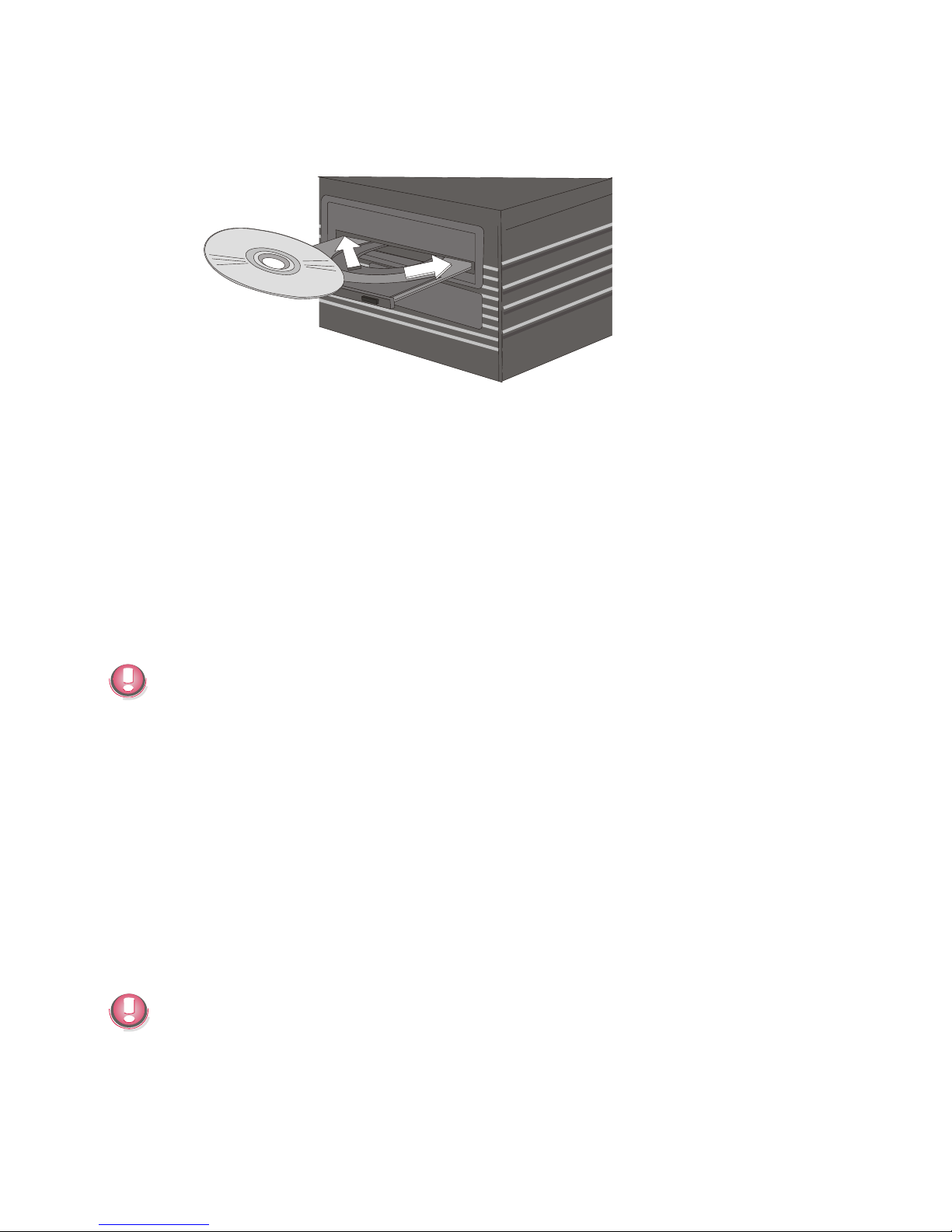
n
Place the disk into the drawer with the disks label facing up. Then restore
the drawer softly until it is locked in the drive.
No tes
n
Never bend a disk.
n
Never write on a disk with a hard object, like a ball-point pen or pencil and
never fix a label directly on the disk.
n
Do not expose disks to direct sunlight and avoid storing them in areas
subject to high temperatures or humidity.
n
Never touch the surface of the disk. Always handle by their edges.
n
For best results, periodically wipe each disk with a soft, dry cloth, gently
rubbing outward from center.
Never use fluids such as petrol, record cleaning or anti-static fluid. Use of
such fluids can damage the disk.
Power Supply Unit (200 W)
The power cord receptacle, the power output socket for the monitor and the
ON/OFF switch are located on the back of the BEETLE /iPRO. At the front
side of the box you will find the ON button which will turn on the system. The
system is automatically switched off, when the operating system is shut
down. Pushing (approx. 5 seconds) the ON button at any time will shut
down the system. The proper function of the On button is defined by the
settings of the operating system and the BIOS.
The power output of the power supply unit is maximum 200 W. The power
supply unit is manually operated to the particular voltage (115/230V) with
the dispatcher at the back side of the BEETLE.
25
POWER SUPPLY UNIT (200 W)
Page 30
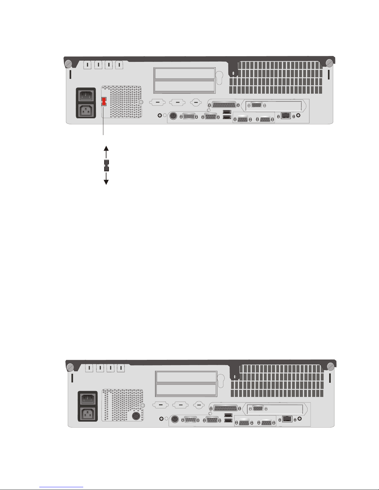
A wrong adjustment of the power output results in a destruction of the power
supply.
Power Supply Unit (272 W)
Depending on the construction level the BEETLE /iPRO is delivered with a
200 W or a 272 W power supply unit. The 272 W power supply unit
automatically adjusts itself to the particular voltage (115/230V), therefore the
dispatcher is missing.
At the front side of the box you will find the ON button which will turn on the
system.
The system is automatically switched off, when the operating system is shut
down. Pushing (approx. 5 seconds) the ON button at any time will shut
down the system. The proper function of the On button is defined by the
settings of the operating system and the BIOS.The power cord receptacle,
the power output socket for the monitor and the power socket for the printer
are located on the back of the BEETLE /iPRO.
POWER SUPPLY UNIT (272 W)
26
COM1 COM2
COM4
CRT
LPT1
COM3
USB
SPK
LAN
MIC
KYBD
100-120 V / ~ 2A max
200-240 V / ~ 1A max
COM1 COM2
COM4
CRT
LPT1
COM3
USB
SPK
LAN
MIC
KYBD
230
100-120 V / ~ 2A max
200-240 V / ~ 1A max
Dis pat cher of the po wer output
115V
230V
Page 31

Configuration Variants
Submodules for the CPU
Various controllers can be plugged in on the CPU. The following is a brief
description of the available options:
LAN Con trol ler 10/100 MBit
Ex works the BEETLE /iPRO is equipped with the LAN Adapter 10/100 MBit
for the incorporation in an Ethernet Network. Alternatively a PCI LAN
Controller 10/100 MBit can be plugged. See the manual “POS Motherboard”
for the settings in the BIOS Setup.
CRT- or TFT-Adapter
Both adapters are installed alternatively. You can connect either a CRT
monitor or a TFT-LCD module with optional touch screen functionality.
Depending on the connected screen, BA7x-A2 (DDC) or BA7x-A/1 (non
DDC), the screen settings are made either via jumper on the motherboard
(non DDC) or automatically via the driver (DDC).
By using the touch screen the COM2 interface is no longer available for
external use. If the BEETLE system is pre-installed ex works, COM2 will be
delivered with a cover.
In stal ling a Sub mo du le
First ensure that the system is switched off and that the power connector is
disconnected.
27
SUBMODULES FOR THE CPU
Page 32
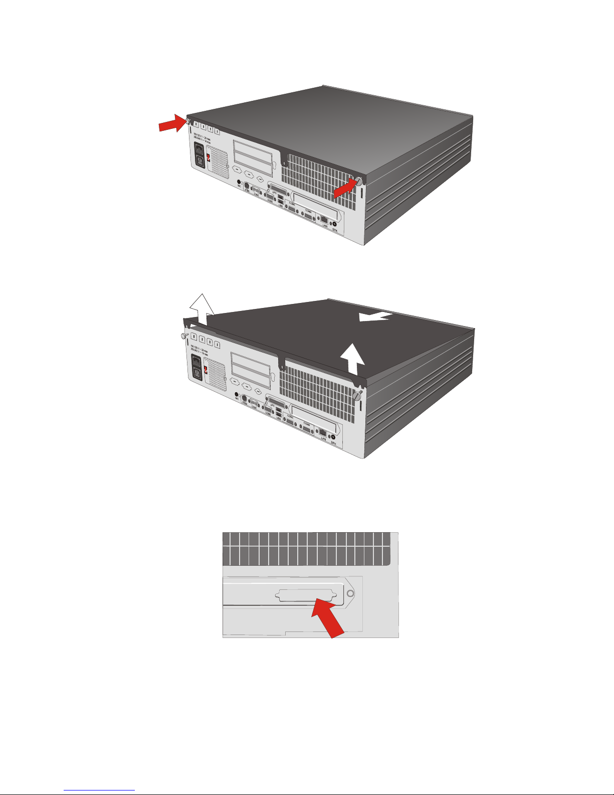
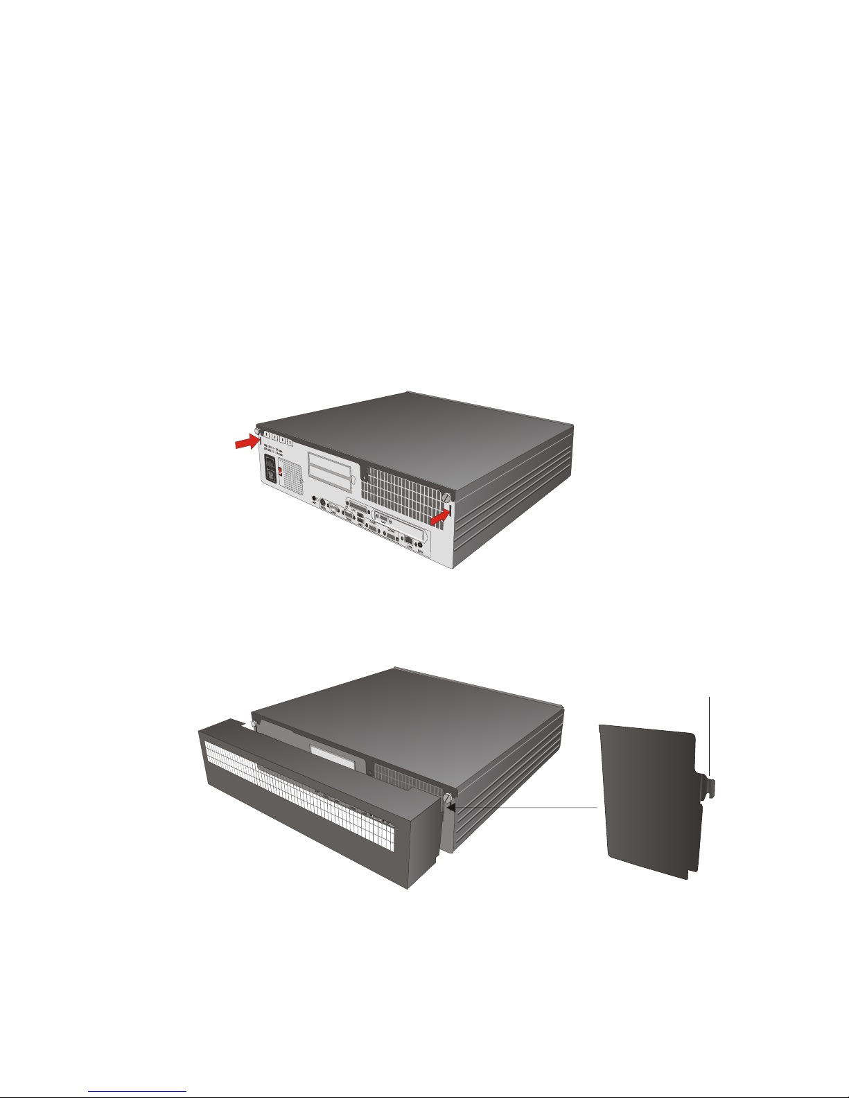
Loosen the two screws at the back side (see arrows).
Lift the top cover at the back side (1) and pull it out of the front guide (2).
Remove the metal cover you require on the back side. Plug in the
submodule.
IN STAL LING A SUB MO DU LE
28
Page 33
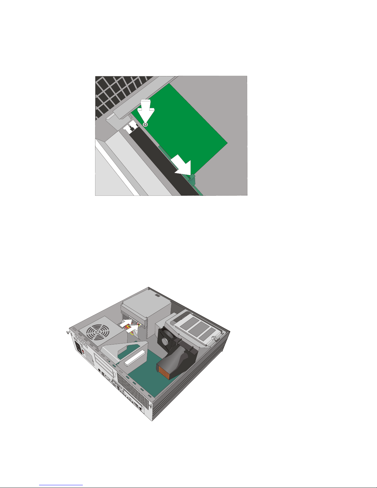
Bring the socket through the recess of the housing. When attaching the
submodule to the motherboard, bend the clamp (1) carefully to the front.
Make sure that the connector is plugged correctly and the pin fitted to the
hole (2).
Screw the connector at the back side. Close the cover and plug the power
plug. You can now switch on the system.
Change of the CD-ROM/DVD Drive
First ensure that the device is switched off and that the power connector is
disconnected.
To chan ge the
CD-ROM/DVD
dri ve open your
BEET LE /iPRO (as
des cri bed on page
28). Pull out all
ca ble con nec tors
(see ar rows).
29
CHANGE OF THE CD-ROM/DVD DRIVE
Page 34
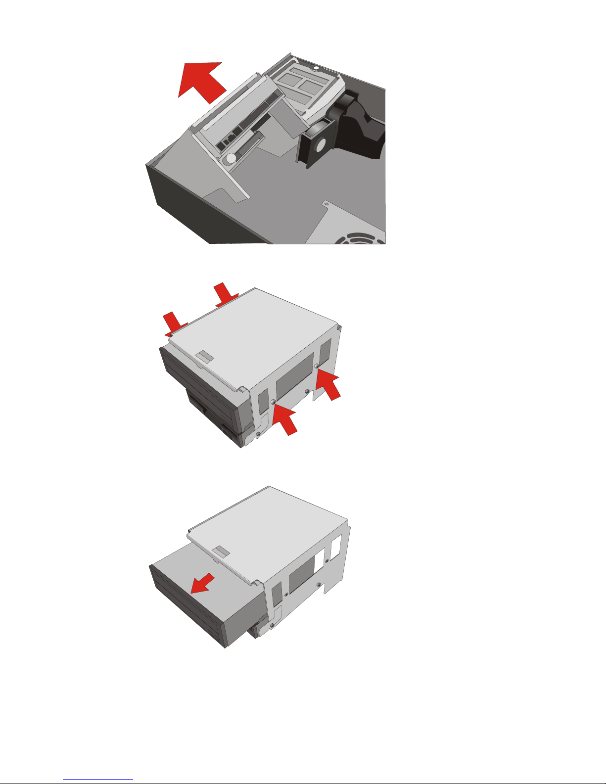
Lift up the dri ve, tilt
the CD-ROM/DVD
hol der and take it
out.
Loo sen the
screws.
Shift the
CD-ROM/DVD
dri ve through the
dri ve hol der.
CHANGE OF THE CD-ROM/DVD DRIVE
30
Page 35
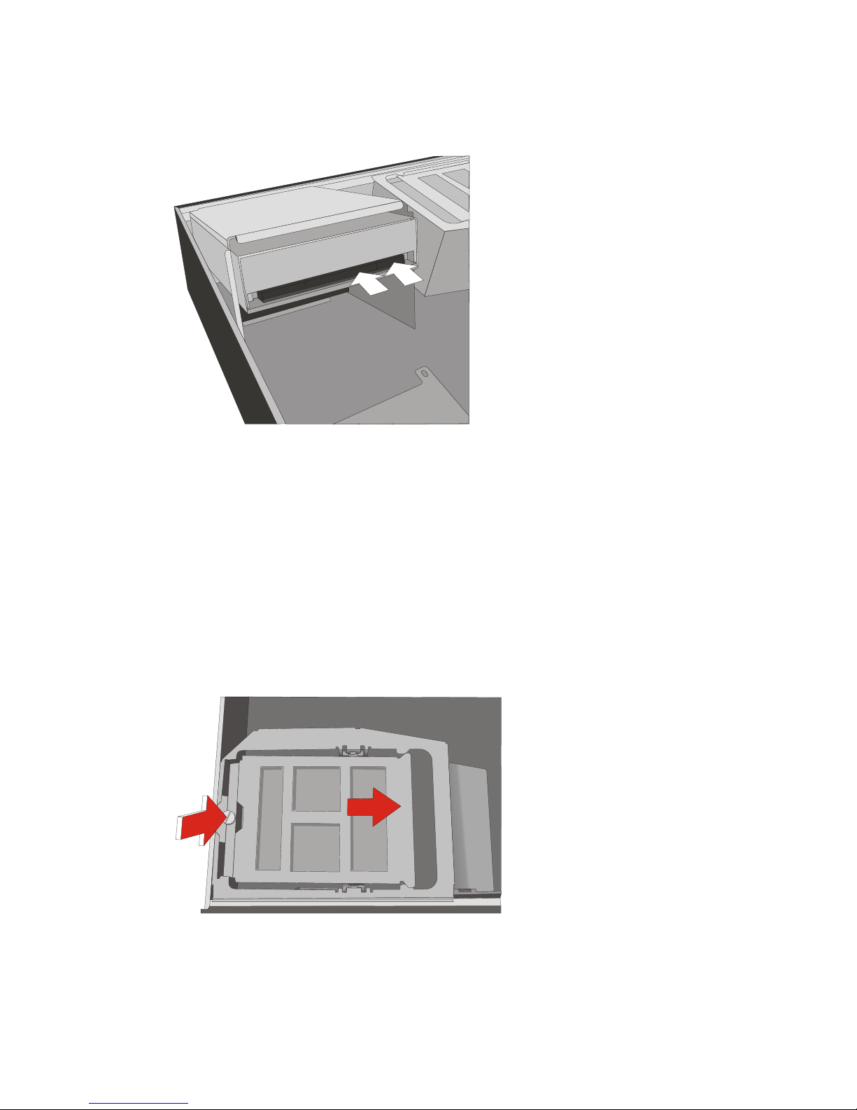
Change the CD-ROM/DVD drive. Make sure that the drive is not mounted in
rotation of 180°. Fasten the new drive with the screws. In sert the
CD-ROM/DVD dri ve hol der.
Tilt the dri ve hol der
to the rear.
Plug in the con nec tors (see
arrows).
Close the cover and reconnect the mains connector. Now you can switch
on the system.
Change of the Hard Disk Drive
First ensure that the device is switched off and that the power connector is
disconnected.
Open your BEETLE /iPRO as des cri bed on page 28.
Loosen the screw (1) and push the hard disk drive in direction of arrow (2).
31
CHANGE OF THE HARD DISK DRIVE
Page 36
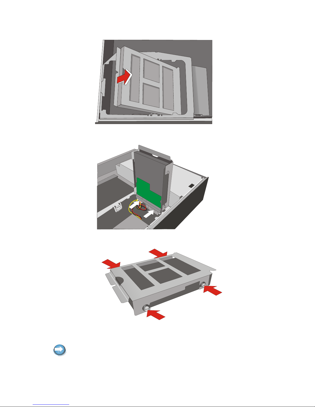
Lift up the dri ve.
Tilt the hard disk hol der and loosen the connecting cables.
Take the holder out and loo sen the four screws at the holder.
Remove the hard disk.
Insert the new hard disk and fix it with the four screws.
Please pay regard to the cor rect di rec ti on of the ports.
CHANGE OF THE HARD DISK DRIVE
32
Page 37
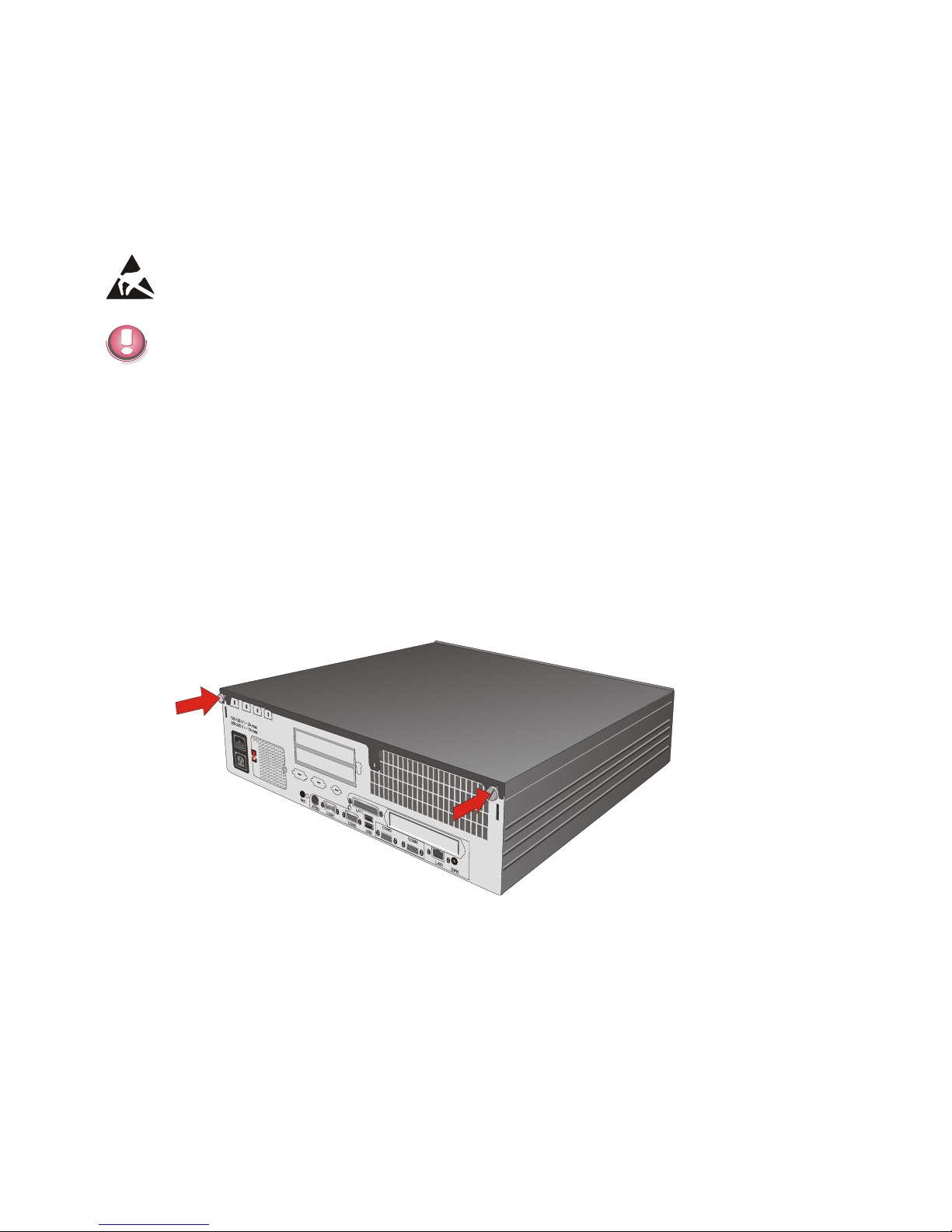
Insert the hard disk holder and connect the cables.
Close the cover and reconnect the mains connector.
Now you can switch on the system.
Installing an Expansion Card
Ex pan sion cards with elec tro sta ti c sen si ti ve de vi ces (ESD) could be mar ked
with this sti cker.
When you handle boards fitted with ESDs (electronic components), you
must observe the following aspects under all circumstances:
n
You must always discharge yourself (e. g. by touching a grounded object)
before working with boards containing ESDs.
n
The equipment and tools you use must be free of static charges.
n
Pull out the power plug before inserting or pulling out boards containing
ESDs.
n
Always hold boards with ESDs by their edges.
n
Never touch pins or conductors on boards fitted with ESDs.
First ensure that the power connector is disconnected.
Loo sen the two screws (see ar rows) at the back of the BEET LE.
33
INSTALLING AN EXPANSION CARD
Page 38
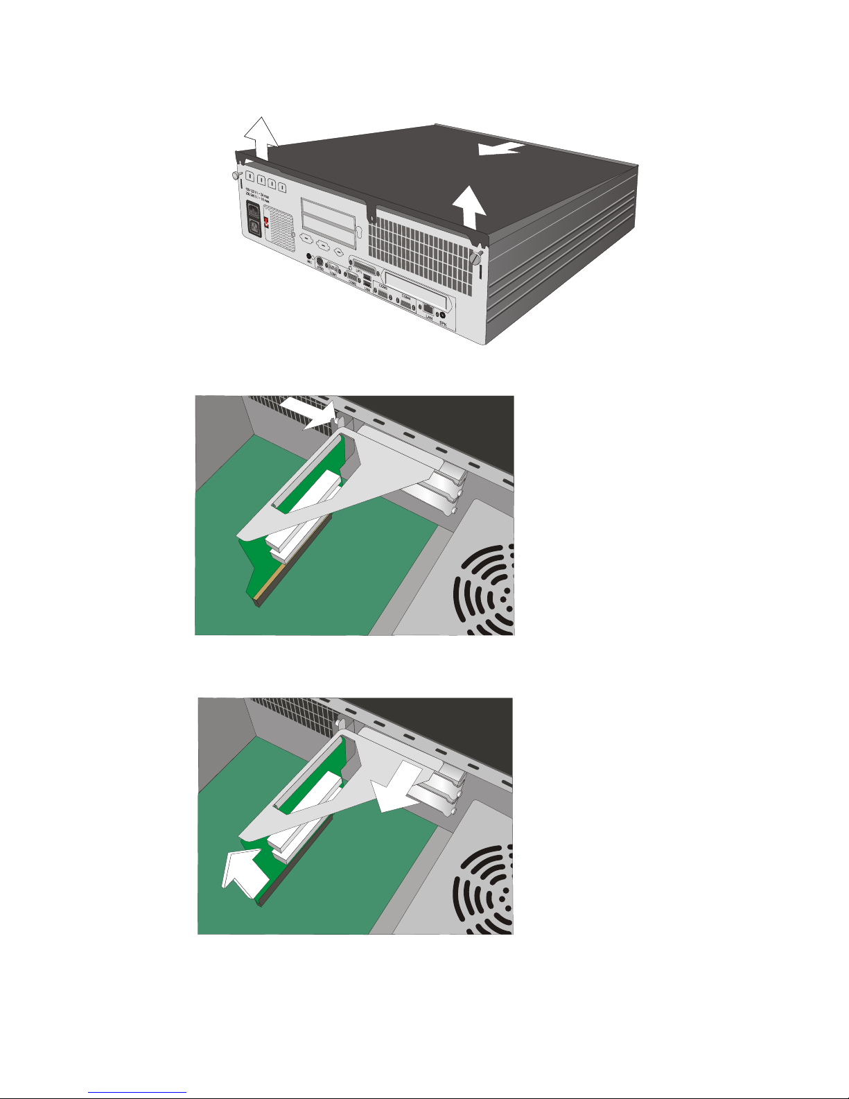
Then lift up the co ver (1) and pull it out of the front gui de (2).
Loo sen the screw at the ri ser board (see ar row).
Pull up the riser board out of motherboard (3) and push it backwards (4).
INSTALLING AN EXPANSION CARD
34
Page 39
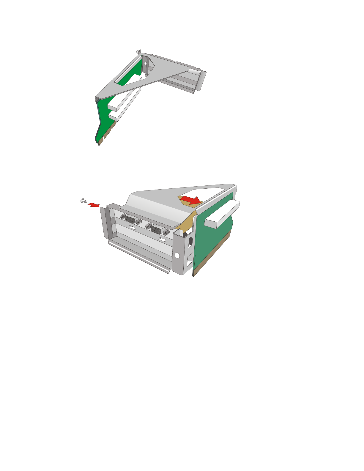
Re mo ve the riser board and the me tal co ver at the back side of the slots.
Plug the ex pan si on card into the con nec tor at the ri ser board (1). Make sure
that the ex pan si on card is con nec ted cor rect ly. Fix the board with the screw
(2).
Plug in the riser board on to the motherboard. Secure the card by tightening
it with the screw that you have removed before.
Close the BEETLE /iPRO with the cover. The mains connector can now be
reconnected and the device switched on.
35
INSTALLING AN EXPANSION CARD
Page 40

Retail Software
The market for retail store solutions presents a broad array of requirements
for the functions in these solutions as well as for the software technologies
used. Moreover, the software and hardware is used internationally, and
must meet a wide range of regional requirements. This means, for example,
that solutions that fulfil the regional requirements of Central Europe may
turn out to be inadequate for Asia or Latin America. Wincor Nixdorf provides
customers world-wide with standard products appropriate to the commercial
and technical complexity of their organizations. In keeping with this strategy,
Wincor Nixdorf has defined a portfolio of in-store solutions that
accommodates this variety of requirements. The portfolio offers in-store
solutions for the different operating system platforms that are prominently
used world-wide (Microsoft and Linux), and also offers varying degrees of
solution complexity. Besides demanding products that will remain viable in
the future, today’s retail customers also require that a solution provider
offers other services, such as project management, customization and
integration services, as well as advice in the selection of basic core
technologies.
Wincor Nixdorf Store Solutions
As an international product provider, we are oriented to market
developments and standards that are available world-wide, allowing us to
offer our customers open solutions and services with guaranteed viability
into the future.
Software must of course meet the customer's needs, and these can often
vary greatly. But for the software to be a long-term success, its design and
implementation must also take into account the fundamental trends and
standards that are emerging in the market. Only if you stay open to the
dynamics of retail, it can be ensured that new commercial trends will be
reflected within the scope of the solutions provided. To accommodate these
dynamics, Wincor Nixdorf must have the appropriate technical expertise.
When working on product development, projects or consulting, this expertise
is essential to effectively meet current as well as future requirements.
WINCOR NIXDORF STORE SOLUTIONS
36
Page 41

Platforms and Products
Solution platforms today are expected to utilize state-of-the-art,
standardized operating systems. Some of the decisive factors in selecting
an operating system in the retail trade include:
n
An operating system should provide software administration mechanisms
to help minimize the total cost of ownership
n
The flexibility of an operating system for use with different hardware and
peripherals
n
Global availability to ensure complete coverage, as well as
n
Scalability with regard to user requirements.
In light of these criteria, the Microsoft operating systems have established
themselves in the market, and the Microsoft Windows platform is now
positioned as an important technological factor.
However, the growing discussion of operating system scalability, as well as
the demand for continued reduction of the total cost of ownership, have led
to the emergence of other operating systems. The strongest trend has been
to Linux. Regardless of the industry involved, Linux offers itself as an
interesting supplement to the world of Microsoft.
In view of this trend, Wincor Nixdorf has defined a software strategy that
accommodates both Linux and the popular Microsoft platform:
Tra ding Post
Trading Post presents itself as an object-based POS solution which uses
the Microsoft Windows operating system throughout. With standardization
concepts for interfacing POS peripherals (OPOS), an innovative, modular
customizing concept and a graphical user interface at the POS terminal,
Trading Post is positioned in markets with demanding requirements for
system architecture and application versatility.
Microsoft platforms and technologies are used in the development of
Trading Post. With its basic standards and technologies - such as the ARTS
data model, the XML Internet standard, the OPOS peripheral control
concept and the Trading Post architecture - Trading Post is a software
solution that satisfies the needs of international retail companies oriented
toward technology and architecture. Trading Post provides plug-ins for the
Cash & Carry and General Merchandise segments.
37
PLATFORMS AND PRODUCTS
Page 42

TP.net
TP.net combines Trading Post’s basic technologies and concepts (e.g.
Microsoft operating systems, ARTS, Microsoft databases, XML or OPOS)
with Microsoft .NET technologies and extensive functionality. This
functionality can easily be extended with the aid of sophisticated
customizing and tailoring mechanisms. Plug-in components meet national or
custom requirements without having to relinquish the advantages that a
standard product has to offer. This feature enables Wincor Nixdorf’s offices
and software development partners to handle software projects on their
own. In the medium term, Microsoft .NET technology will make it possible to
run the same application on mobile devices.
TPLi nux
CALYPSO/TPLinux runs under the Linux operating system both on the store
server and on the POS system. This homogeneous operating system
environment means that the application can be deployed in a client/server
environment at hypermarkets or on a stand-alone system. In addition, using
Linux on POS systems not only supports international retailers’ IT migration
strategies but is also ideal for providing dedicated add-ons such as a
POS-touch-GUI and extending the product on the basis of state-of-the-art
technologies. Wincor Nixdorf has demonstrated this with TPLinux which is
the direct successor to CALYPSO. Featuring new technologies (XML
interfaces, Java, Web GUI for the back store, and relational databases), this
product is the foundation for a new generation of Linux front store software
that unites innovative technologies, CALYPSO’s internationally proven
functionality, and great flexibility in communicating with other systems in a
given retail IT infrastructure.
Tech no lo gy eva lua ti on
The further development of Wincor Nixdorf retail solutions takes place in
dialog with its customers. Before being included in existing products, new
trends and technologies are carefully examined with regard to their
readiness for the market. To ensure market acceptance and market
orientation in the selection of technologies, Wincor Nixdorf conducts
technology evaluation projects with its customers and partners. This
significantly reduces technological risks.
PLATFORMS AND PRODUCTS
38
Page 43

Starting up the System
Start and Runup Behaviour
After installing the BEETLE /iPRO, switch on the On/Off button at the front
panel.
The system first performs an automaticself-test to test its basic functions.
For example, you may see the following message (irrespective of processor
type) on the four-line cashier display or on the monitor:
xx/xx is the place holder of the BIOS version number
The system then determines the medium from which the operating system
and POS application are to be booted. Each medium is assigned a logical
drive according to the configuration of your BEETLE /iPRO.
The following media can be assigned a drive:
Starting up the system
n
Disk
n
Network
n
Hard disk
n
CD-ROM
The logical drives are designated A:, B:, C: and D:.
If the system is to be booted from the floppy disk, this medium must always
be assigned drive A:. The network is always assigned to the C: drive during
the runup procedure. The hard disk can be assigned to the C: or D: drive.
The system can only be started from the hard disk if the disk has been
configured as the C: drive.
39
START AND RUNUP BEHAVIOUR
WN ID xx/xx Date
Page 44

Corresponding to the Setup configuration the modular BEETLE /iPRO POS
system can be booted from the following drives:
n
Floppy disk in drive A:
n
Hard disk in drive C:
n
CD-ROM in EL TORITO format
n
Network adapter with BOOTPROM
Please mind that the storage medium must be system-boot-capable.
If the operating system has started up without error, the POS application
software is automatically booted if necessary.
A message is displayed as soon as the BEETLE /iPRO is ready for
operation. For more detailed information, see the description of your
application program.
START AND RUNUP BEHAVIOUR
40
Page 45

Appendix
Technical Data for the BEETLE /iPRO
41
TECHNICAL DATA FOR THE BEETLE /IPRO
Box
Width 437 mm 17.2“
Depth (without cable cover) 431 mm 17.0“
Depth (with cable cover) 501 mm 19.7“
Height 123 mm 4.8“
Weight 10.9 kg 24 lbs
Cli ma tic ca te go ry
Ope ra ting IEC 721-3-3 Class 3K3 +5°C to +40°C
Trans port IEC 721-3-2 Class 2K2 -25°C to +60° C
Sto ra ge IEC 721-3-1 Class 1K2 +5°C to +40° C
In put vol ta ge 100 - 120 VAC
200 - 240 VAC
Max. po wer con sump ti on 3A/ 6A
Fre quen cy of sys tem vol ta ge 50 - 60 Hz
Mass storage devices
internal accessible 2 x 3.5“ HDD bays 1” height
“external” accessible 1 x 3.5“ FDD bay for 1“ height or
1 x 5.25" CD ROM/DVD bay for 1.65" height
PC Extension slots 2 x PCI extension slots version
Page 46
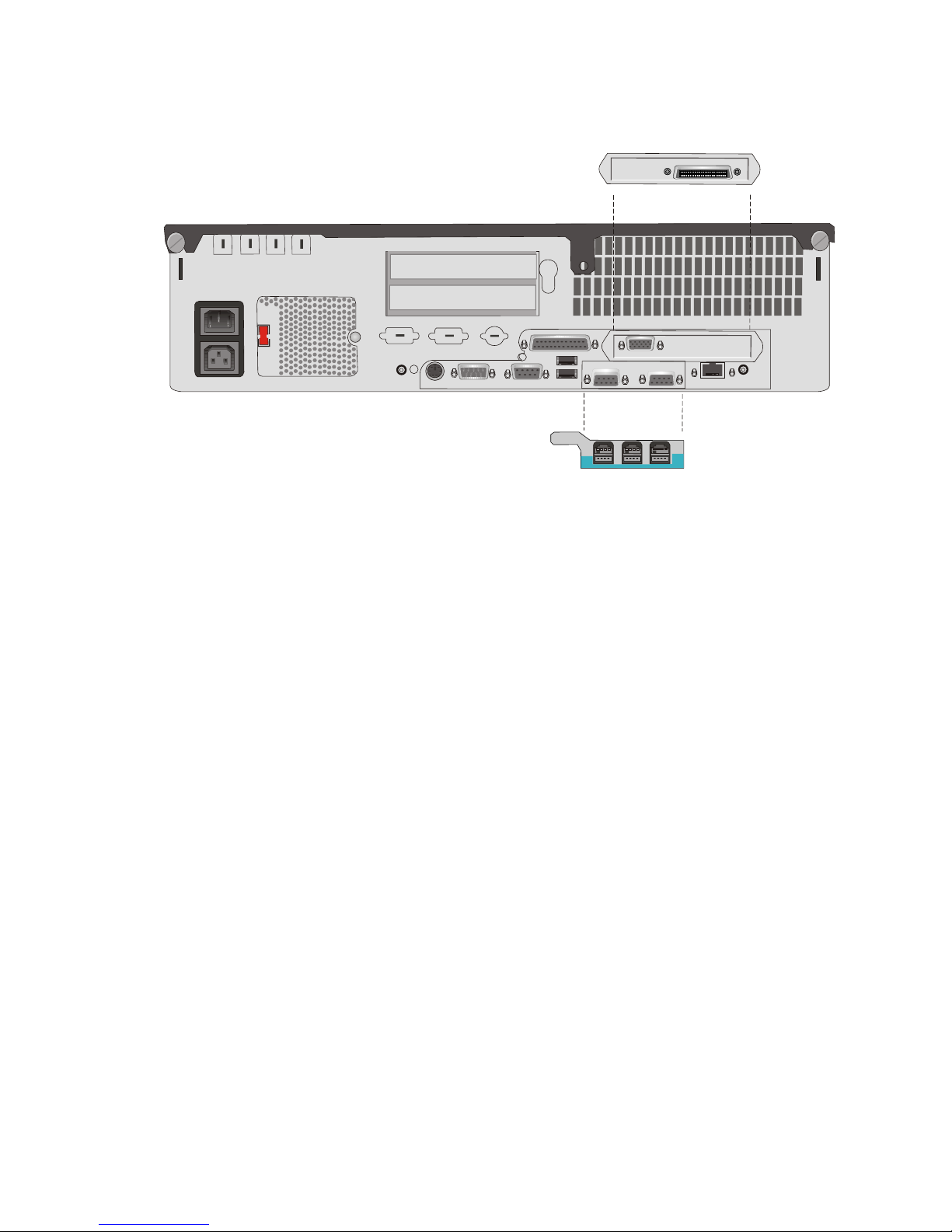
Back Panel of the BEETLE /iPRO
Back Pa nel of the BEET LE /iPRO (stan dard, 200W po wer supp ly, with op tions)
BACK PANEL OF THE BEETLE /IPRO
42
COM1 COM2
COM4
CRT
LPT1
COM3
USB
SPK
LAN
MIC
KYBD
230
100-120 V / ~ 2A max
200-240 V / ~ 1A max
USB USB USB
12V
PLINK-TFT
Page 47

Glossary
Bit
A bit is a binary digit (0 or 1). It is the smallest unit used in data processing.
BPP
Bits per Pixel, depth of colour.
Controller
Serves to control data input and output in a data processing system or
between a computer and the connected peripherals.
CPU
Abbreviation of central processing unit. It includes the main components of
a data processing system. The CPU monitors all operations and provides
data and programs. It comprises the control unit for input and output, the
computer and the main memory, divided into ROM and immediate access
storage.
Interface
Designates the transition point between different hardware units and
software units or between hardware and software units of computers or their
peripherals.
JEIDA
Abbreviation of Japan Electronic Industry Development Association.
Industry standard for memory cards.
Operating system
Refers to all programs that are a component of a computer and are required
for operating the system and executing application programs.
PCMCIA
Abbreviation for Personal Computer Memory Card International Association.
Industry standard for memory cards.
Peripherals
Devices serving as an input/output device or storage for a computer. This
includes, for example, document readers, keyboards, printers and disk
storage.
43
GLOSSARY
Page 48

Plug and Play (PnP)
PnP means the automatic recognition of hardware components by the
system. Thus the installation, integration and configuration of new
components is made substantially easier.
Server
This is a computer connected to a local network and whose services are
available to all of the network subscribers, e.g. a print server for printing the
data from all of the network subscribers on the printer connected to the
server.
TFT LCD
The surface of the display consists of pixels, which are the result of three
transistors (for each basic colour one). Therefore the name thin film
transistor active matrix is used.
VGA
Stands for Video Graphics Array and is the interface for connecting colour
monitors.
GLOSSARY
44
Page 49

Abbreviations
BIOS Ba sic In put Out put Sys tem
BPP Bits per Inch
COM Com mu ni ca ti on Port
CPU Cen tral Pro ces sing Unit
CRT Cat ho de Ray Tube
cUL ca na da Un derwri ters La bo ra to ries
DIMM Dual In li ne Me mo ry Mo du le
EPROM Era sa ble Pro gram ma ble Read Only Me mo ry
FD Flop py Disk
GS “Ge prüf te Si cher heit” (Tes ted Sa fe ty)
HDD Hard Disk Dri ve
ISA In du stri al Stan dard Ar chi tec tu re
ISO In ter na tio nal Stan dardi za ti on Or gani za ti on
LAN Lo cal Area Net work
LBA Lo gi cal Block Ad dres sing
LED Light Emit ting Di ode
LPT Line Prin ter
PCI Pe ri phe ral Com po nent In ter con nect
PCMCIA Per so nal Com pu ter Me mo ry Card In tern. As so cia ti on
PnP Plug and Play
RAM Ran dom Ac cess Me mo ry
ROM Read Only Me mo ry
SCSI Small Com pu ter Sys tems In ter fa ce
SIMM Sing le In Line Memory Module
SRAM Sta tic Ran dom Ac cess Me mo ry
SVGA Su per Vi deo Gra phics Ar ray
TFT Thin Film Tran sis tor
UL Un derwri ters La bo ra to ries
USB Universal Serial Bus
45
ABBREVIATIONS
 Loading...