

Page 1
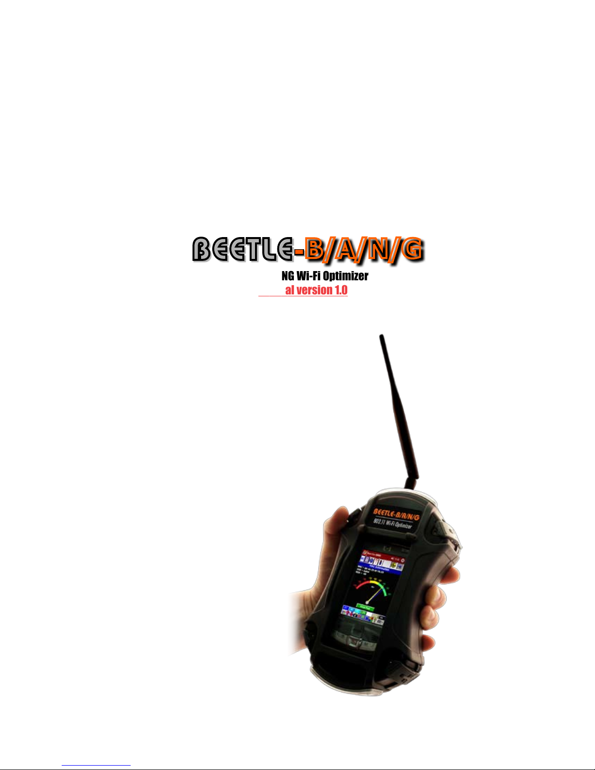
BEETLE-
802.11 BANG Wi-Fi Optimizer
manual version 1.0
B/A/N/G
Page 2

Contents
Beetle-B/A/N/G/iPAQ Interface Hardware
Unpacking Your Beetle-B/A/N/G............................................................................... 2
Starting Up Your Beetle-B/A/N/G.............................................................................. 3
Antenna Specifications......................................................................................... 4
Accessories....................................................................................................... 5
Beetle-B/A/N/G Power System................................................................................. 5
Troubleshooting.................................................................................................. 6
Hardware Connection Issues........................................................................ 6
Software Installation / Re-Installation............................................................. 7
Operational Tips.................................................................................................. 8
Battery Life............................................................................................. 8
Surveying............................................................................................... 8
Optimization........................................................................................... 8
Beetle-B/A/N/G Accessories Sheet............................................................................. 10
Swarm Indoor/Outdoor Site Survey Mapping Software..................................................... 11
Remote Manager PC Monitoring Software................................................................... 12
Beetle-B/A/N/G iPAQ Interface Software
Introduction....................................................................................................... 13
Installation of Software......................................................................................... 13
Getting Started................................................................................................... 13
Quick Tour......................................................................................................... 14
BAG Toolbar Options............................................................................................. 14
Packet Processing................................................................................................ 14
MAC List........................................................................................................... 15
Individual MAC.................................................................................................... 15
Multipath................................................................................................ 16
802.11n Information................................................................................... 17
802.11n HT Capabilities.............................................................................. 18
802.11n Beamforming Capabilities................................................................. 19
Channel Frequency Response....................................................................... 20
WISP Antenna Alignment............................................................................ 21
Security.................................................................................................. 22
RSSI Over Time........................................................................................ 23
Security Authorization Lists.......................................................................... 25
GPS Information....................................................................................... 26
System Information................................................................................... 27
Power Profile........................................................................................... 28
Chameleon Software............................................................................................ 29
1
Page 3
Beetle-B/A/N/G user’s manual and software
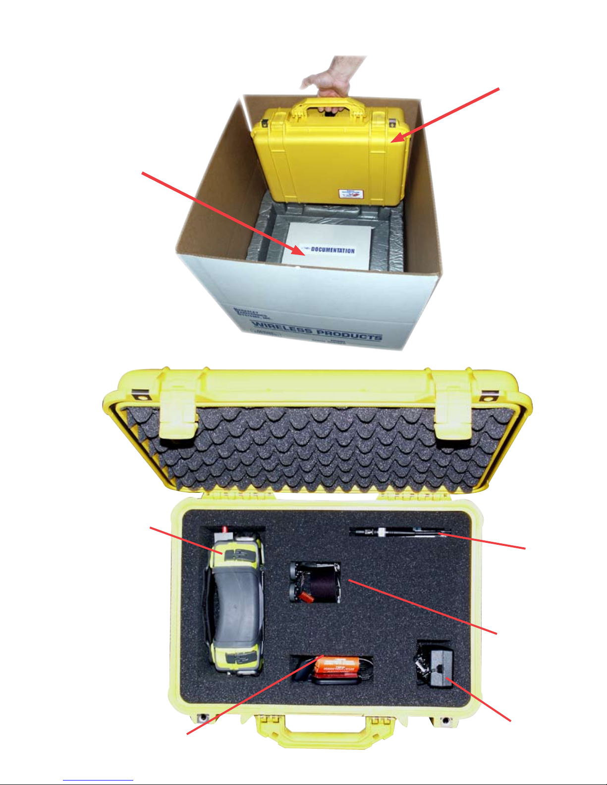
Unpacking Your Beetle-B/A/N/G
Beetle-B/A/N/G with
accessories
Beetle-B/A/N/G unit
includes calibrated
receiver, iPAQ and
battery system
iPAQ charging/
data USB cradle
omni directional
antennae (2.4
GHz & 5 GHz)
larger case handle,
hex keys & spare
data/power cable
for iPAQ
Beetle-B/A/N/G AC
power adapter
2
Page 4
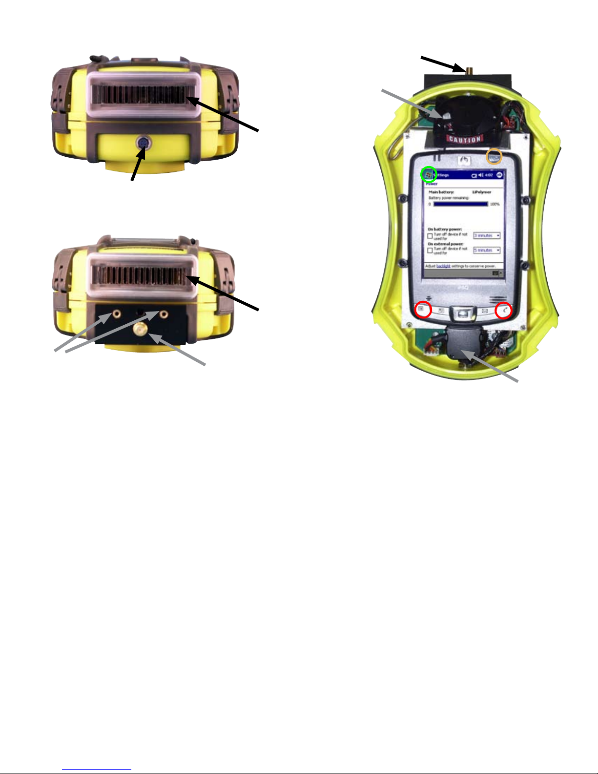
Beetle-B/A/N/G BOTTOM VIEW
Beetle-B/A/G Receiver Power/
Charging Connector
Beetle-B/A/N/G TOP VIEW
SMA Male antenna input
Warning: Maximum input 0 dBm NO DC Input
Air Intake
Cooling Fan
Air Vent
(Output)
Air Vent
(Intake)
DF Antenna
screw mounts
SMA Male antenna input
Warning: Maximum input 0 dBm NO DC Input
iPAQ Power/Charging Connector
About Your Beetle-B/A/N/G
Unpack and assemble your Beetle-B/A/N/G unit as shown. Your Beetle-B/A/N/G is a self-contained Wi-Fi optimizer. The user interface (iPAQ),
antenna and power connections are all accessible, but there is usually no need to open the protective, yellow hard case. If you should need
to open the case to remove the iPAQ or address the internal connections, simply unhook all 4 latches on the case. Remove top cover to reveal
iPAQ, cooling fan and power/data connector. The Beetle-B/A/N/G receiver and battery system are below these components. The iPAQ may be
disconnected and removed by users but the other components should only be accessed by Berkeley technicians. Removing such components
will void your hardware warranty.
Power up the iPAQ by pushing the power button in the upper right corner of the iPAQ. Connect the appropriate frequency antenna to the SMA
antenna input. iPAQs shipped by BVS are optimized for the Beetle-B/A/N/G.
iPAQs supplied by BVS have the Beetle-B/A/G software pre-installed. If you need to install the Beetle-B/A/N/G software, see the software installation/re-installation section.
Tap the windows Start icon in the upper left corner and then choose Beetle-B/A/N/G in the pulldown menu. If the Beetle-B/A/N/G does not appear
in the pulldown menu, tap on the “Programs” folder. Tap on the Beetle-B/A/N/G icon.
Running the Beetle-B/A/N/G software will power the Beetle-B/A/N/G Wi-Fi optimizer.
If the Beetle-B/A/N/G software loses communication with the Beetle-B/A/N/G, perform a soft reset by pressing the iPAQ’s reset button. If communications problems persist, perform a hard reset by holding down the two outer buttons on the front of the iPAQ while holding in the soft reset
button. Remember, hard resets erase all data collected and software installed so backup all data and see software re-installation for details.
3
Page 5
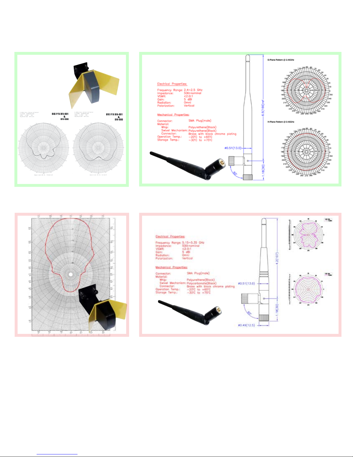
2.4 GHz Direction Finding
Corner Reflector
2.4 GHz Omni-Directional (7.5” long)
4.9/5 GHz Direction Finding
Corner Reflector
4.9/5 GHz Omni-Directional (5.5” long)
4
Page 6
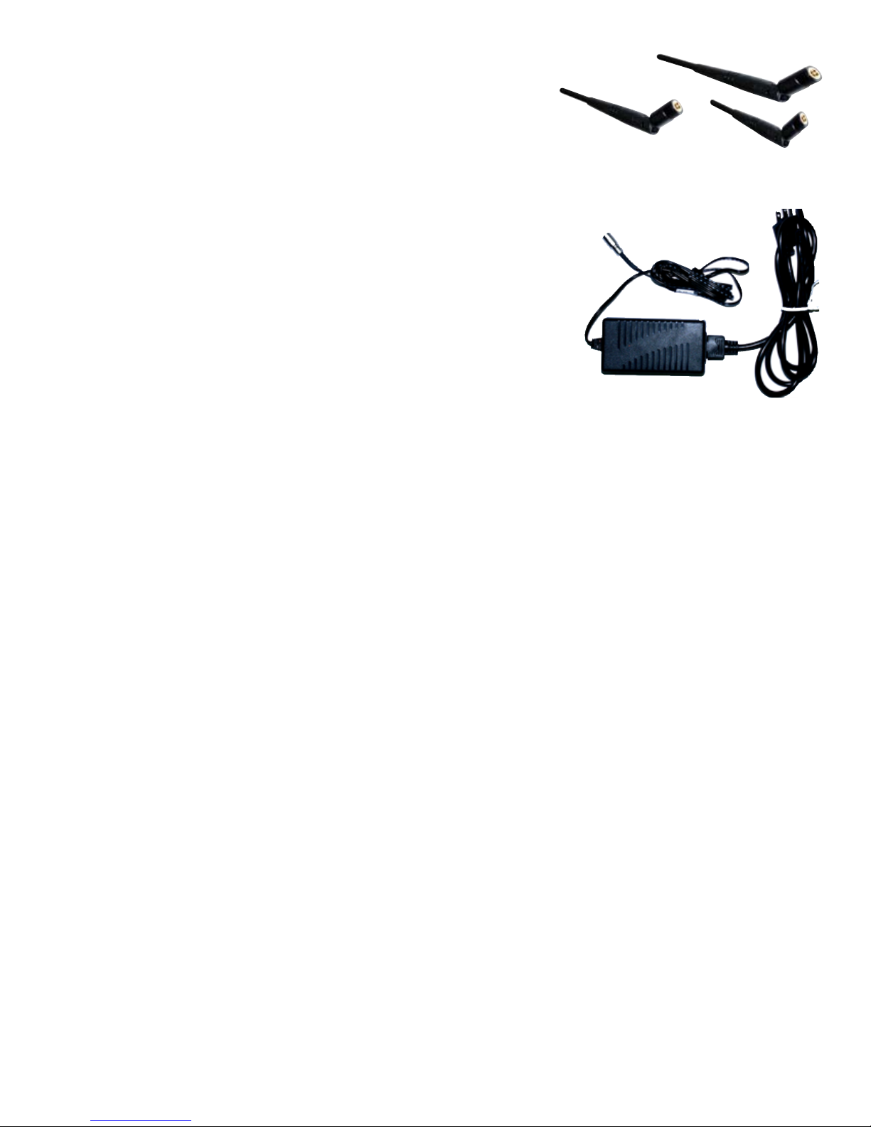
Accessories
Your Beetle-B/A/N/G includes the following accessories: 3
antennae, spare data/power cable (for iPAQ), larger case grip
with hex key tools, an AC power/charging adapter, user’s manual, SD software install card and CD-ROM software installer.
Beetle-B/A/N/G Power System
Beetle-B/A/N/G offers three choices of powering: internal
Li-PO battery, external 12VDC (11-15 V) power supply or external auxiliary battery. The power smoothly transitions from one
source to another providing uninterrupted functionality while
plugging or unplugging the external supplies. The IPAQ runs
from the built-in battery or from an internal regulated 5VDC
supply when the external 12VDC is applied. Both batteries –
the IPAQ built-in battery and the system Li-PO battery – are
charged when the external 12VDC is applied. The charge time
is 3 to 4 hours depending on the depth of discharge and the
ambient temperature. The run time exceeds 3 hours when the
batteries are completely charged.
The IPAQ battery is usually depleted at the same time as the
system Li-PO battery. However, if the IPAQ battery is low while
the system is still running, the equalizing mode of operation
is provided. In this mode the IPAQ is powered from the system Li-PO battery. To enter this mode, set the IPAQ to “USB
Charge” ON. This may prolong the total system run time. Do
not keep the “USB Charge” setting ON all the time since it
will drain the system battery faster, eventually reducing the
system run time.
It is recommended to keep the IPAQ and/or the application
software OFF while charging. The system supports a simultaneous charge and run though the charge time may substantially increase due to increased internal temperature.
When the internal temperature exceeds the maximum allowed
for the Li-PO batteries the system automatically interrupts
the charge. The red LED that can be seen through the bottom
transparent hatch will be blinking. The same LED is solid ON
when the charge is going and turns OFF completely when the
charge is finished.
5
Page 7
TROUBLESHOOTING
IPAQ AND Beetle-B/A/N/G POWER ISSUES
Your Beetle-B/A/N/G Wi-Fi optimizer and your HP iPAQ are
both charged and/or powered through the 4 pin power port at
the bottom of the Beetle-B/A/N/G. Both the receiver and iPAQ
have their own internal batteries but both of these batteries are
maintained and charged through the 4 pin power port. Here are
some tips for prolonging the life of your hardware and data:
• The iPAQ’s internal batteries are discharged when the iPAQ is
“off” to maintain its memory. Keep the iPAQ charged! Charge
it at least once a week!
• If the iPAQ’s batteries are completely discharged, it will need
several hours of charging before it can be powered on or even
flash the charging (yellow) LED. Once the iPAQ is charged
it may need to be soft or hard reset before powering on. The
Beetle-B/A/N/G software must be re-installed from an SD card
or downloaded via ActiveSync. In order to install software
using the SD card, the iPAQ must be removed.
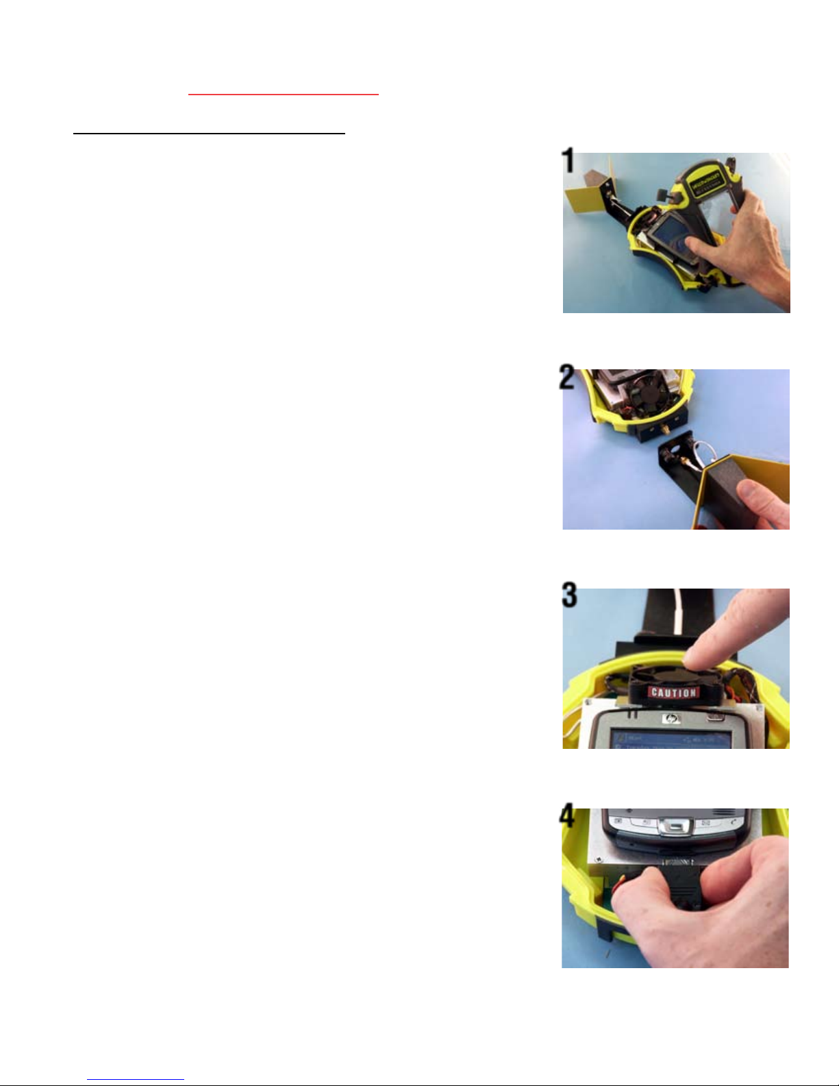
1. Unhook all 4 latches and remove the top cover.
1
2
2. Remove the (optional) DF antenna by loosening the 2 thumb
screws and unscrewing the antenna connection.
3. Be sure not to touch the air intake cooling fan while it is
spinning. This fan spins to regulate the temperature of the
receiver and batteries so be sure to keep all obstructions and
objects from the fan’s air path.
4. Remove the power/data connector at the bottom of the iPAQ.
This connector provides communication and charging/battery
power to the iPAQ.
You may now remove the iPAQ from its holder for other uses.
3
4
6
Page 8
HARDWARE CONNECTION ISSUES
When the Beetle-B/A/N/G software is started, the following screen will appear if
the software was unable to detect the hardware. The following may cause this:
1. Loose connection to iPAQ serial cable. The serial cable may not be fully seated
in the power/data slot on the bottom of the iPAQ. Check the connection. A soft
boot of the iPAQ may be required. Soft booting is accomplished by pressing the
recessed reset button on the iPAQ with the stylus.
2. Low batteries. Test this by running off of A/C power using the supplied 4 pin
power connection to the Beetle-B/A/N/G and the iPAQ. The charge (Yellow) LED
on the iPAQ should be flashing if the cable is connected correctly and the BeetleB/A/N/G red power LED should be on.
3. COM port is held open. Soft boot the iPAQ to clear out the possibility that the
serial port is being held open by a previously running copy of the Beetle-B/A/N/G
software.
SOFTWARE INSTALLATION/RE-INSTALLATION
The Beetle-B/A/N/G software can be installed/re-installed in via the included SD
card. There are 3 different folders for 3 different platforms:
iPAQ folder:
Beetle-BANG iPAQ software
MS .NET Compact Framework for iPAQ
PC folder:
Beetle-BANG Chameleon for PC
PC/XP folder:
ActiveSync for Windows XP PCs (not Vista)
All applications can be installed from their setup files.
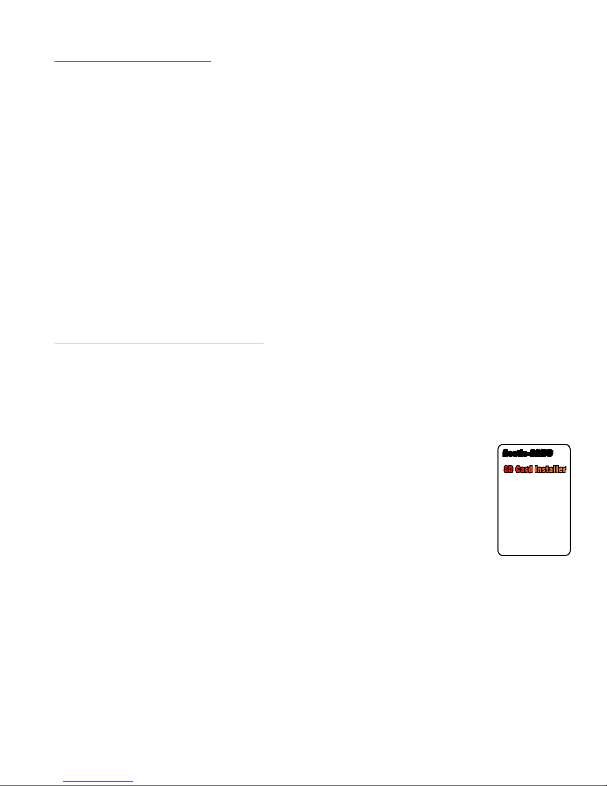
Beetle-BANG
SD Card Installer
•Insert card into SD slot on top of iPAQ
•Tap on “Start” icon on top left of screen
•Tap on “Programs” in menu
•Tap on the “File Explorer” folder
•Choose “My Device”
•Tap on “SD Card” or “Storage Card”
•Tap on “install” executable
•Choose iPAQ model for installation and
tap on that “install” button
------------------------------------------------
This SD card contains install files for
both iPAQ and PC platforms.
DATE:________
7
Page 9

OPERATIONAL TIPS
SURVEYING
While surveying, Beetle-B/A/N/G achieves the most accuracy
when antenna is at a vertical 90 degree angle and completely
perpendicular to the ground or floor.
OPTIMIZATION
Remember that your iPAQ comes from the BVS factory optimized for powerful spectrum analysis right out of the box, but
sometimes these optimized settings can be lost (back to HP’s
factory defaults) when the iPAQ’s battery completely drains.
The following are procedures for:
Disabling Bluetooth and 802.11 on an iPAQ
It is essential when running your Beetle-B/A/N/G software that
you do not have either 802.11b or Bluetooth running on the
same iPAQ. This will interfere with Beetle-B/A/N/G measurements in the 2.4 GHz band.
Turning Off Bluetooth
HP iPAQ 27xx series:
From the main screen on the iPAQ, select the antenna icon in
the lower right-hand portion of the screen. Then choose the
Bluetooth button to turn off Bluetooth.
The blue LED on the iPAQ should not be flashing when the
radio is off.
Turning Off 802.11b
HP iPAQ 27xx series:
From the main screen on the iPAQ, select the antenna icon in
the lower right-hand portion of the screen. Then choose the
Wi-Fi button to turn off 802.11b.
Battery Settings
NOTE: In order to prevent the Ipaq from freezing when running
Beetle-B/A/N/G software, make sure to:
1. ALWAYS leave the checkboxes in the SETTINGS/SYSTEM/
POWER screen unchecked. Power-save mode will lock up the
8
Page 10
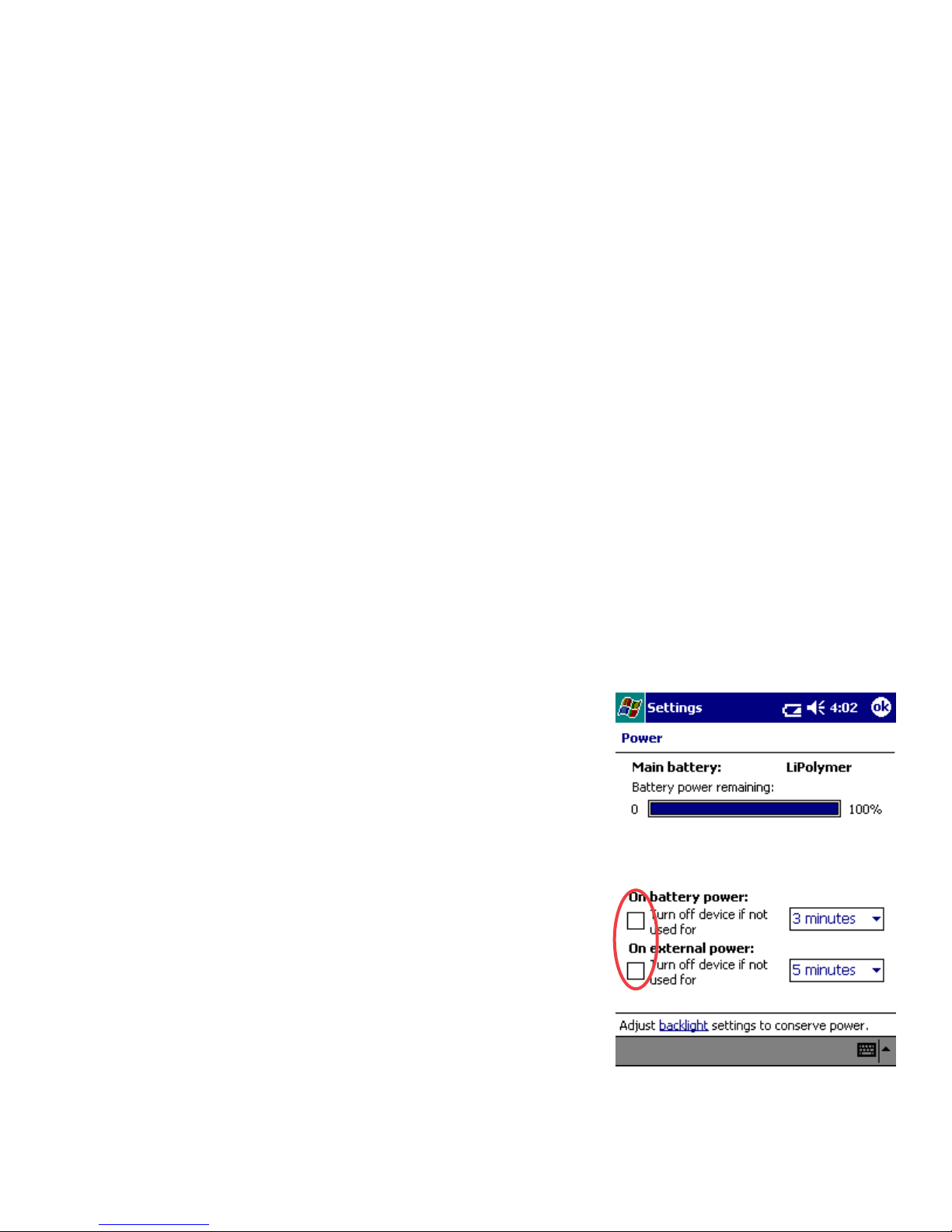
application due to the fact that the application is stopped while
communicating with the hardware..
2. Make sure that the battery level on the Ipaq remains above
40%. The serial card interface may cease to operate when the
battery level is under 40%.
To resolve the freeze, simply press the soft reset button on the
iPAQ with the stylus.
Disabling Screen Saver on an iPAQ
DockWare (by default) runs a screen saver with a calendar
on any new iPAQ (47xx series). This could interfere with the
operation of Beetle-B/A/N/G software. To disable:
1. Tap on the Windows icon in the upper-left corner of the iPAQ
screen.
2. Tap “Programs” in the menu.
3. Tap on “DockWare”.
4. Once running, tap-and-hold on the screen.
5. Uncheck “Start Automatically”.
6. Now tap the upper right corner of the screen to terminate
DockWare (where the ‘X’ would usually be).
7. DockWare is now disabled. It will need to be disabled again
if the batteries completely discharge on the iPAQ.
Choose Settings and then choose System settings at the bottom. Select battery icon for Power
Settings to access this screen. These power settings come unchecked from the BVS factory to
ensure Beetle-B/A/G software runs optimally.
9
Page 11
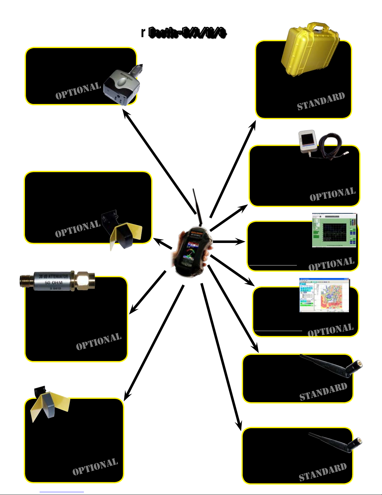
Accessories for your
OPTIONAL
OPTIONAL
OPTIONAL
OPTIONAL
STANDARD
STANDARD
STANDARD
STANDARD
OPTIONAL
OPTIONAL
OPTIONAL
12VDC to 110VAC car cigarette
lighter power inverter
75 Watts output
P/N BB-12V
$ 35.00
4.9/5 GHz Direction Finding Antenna
with mounting bracket, cable & SMA
male
9 dBi gain
P/N 5NE
$ 250.00
Beetle-B/A/N/G
Rugged Carrying Case
ABS Plastic
P/N P-CASE
$ 100.00
External Li-Ion battery pack
with belt clip (+4 hours runtime)
P/N BATT-PK
$ 375.00
30 dB attenuator pad for use with
directional antennas (between
DF antenna & BumbleBee) SMA
male to female
P/N bbpad30
$ 30.00
Remote Manager
802.11b/a/n/g monitoring software
Ask for a Quote
Swarm
802.11b/a/n/g mapping software
Ask for a Quote
2.4 GHz Omni Antenna
SMA male swivel
P/N S151AM-2450S
$ 25.00
2.4 GHz Direction Finding
Antenna with mounting bracket, cable & SMA male
9 dBi gain
P/N 2ND
$ 250.00
10
4.9/5 GHz Omni Antenna
SMA male swivel
Co-Linear Dipole 5 dBi VSWR 1.8:1
P/N K181AM-5250S
$ 25.00
Page 12
TM
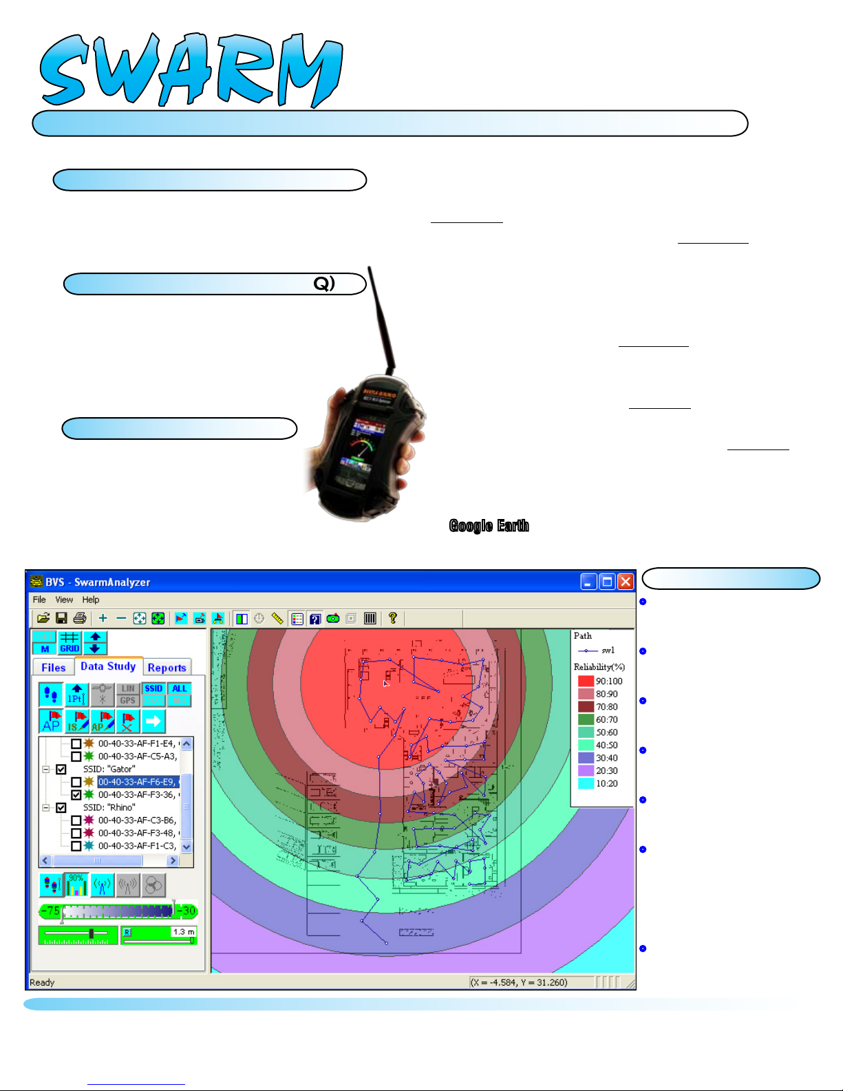
SWARM
802.11b/a/n/g Wi-Fi Indoor/Outdoor Site Surveys
Create Survey Maps:
Swarm Projector (PC)
1
Import any bitmap for use in your Beetle B/A/N/G
Create geo-coded site files for analysis
Constant Realtime Wi-Fi Surveys:
Swarm Collector (iPAQ)
2
Scan all 802.11 channels on BOTH 2.4 GHz and 5 GHz
JPEG snapshots of any survey screen
Collect survey data automatically via GPS
Collect data by manually tapping touch-screen
Coverage Reliability Analysis:
3
Swarm Analyzer (PC)
Plot surveys in multiple graphical and table views
Plot coverage by APs or AP channels
Locate unknown APs’ positions
Print and export plots into bmp files for spreadsheets
Create KML file for plotting coverage over Google Earth™
Use Beetle 802.11b/a/n/g Wi-Fi receiver hardware for
handheld surveys using a touch-screen interface.
Swarm™ combines the power of realtime Beetle® 802.11b/a/
n/g Wi-Fi measurements with GPS geo-coding accuracy.
First, create your survey bitmaps with both Linear and GPS
PROJECTOR software. Next, simply walk or drive to any spot
with GPS reception while Swarm™ COLLECTOR scans all
802.11b/a/n/g channels and correlates them to your exact
location automatically via GPS or manually by tapping on the
touch-screen. GPS measurements provide both LAT and LON as
well as time stamping for a complete Wi-Fi survey path anywhere in the world. Swarm™ COLLECTOR allows JPEG screen
snapshots to be taken at particular points of interest throughout
the survey. Finally, survey data such as RSSI, MAC and SSID
may be exported into Swarm’s ANALYZER for further mapping
coverage studies in multiple graphical and tabular layouts. In
areas with little or no GPS reception, Swarm™ ANALYZER only
needs a few reference points to fill in the locations for the rest
making it effective for quick outdoor studies. Surveys may be
exported further into KML files for plotting in applications such
Google Earth™.
as
Features:
•Create survey bitmaps with BVS’
Linear or GPS Projector software
•Collect data by using GPS position
for outdoor surveys
•Collect data by manually tapping
locations for indoor studies
•Choose any 802.11b/a/n/g Wi-Fi
channels to scan
•JPEG screen snapshots may be
taken throughout the survey
•Survey data such as RSSI, MAC
and SSID is exported into Swarm
Analyzer for further mapping cov
erage studies in multiple graphical
and spreadsheet layouts
•Surveys may be exported further
into KML files for plotting in
applications such as GoogleEarth™
OPTIONAL SOFTWARE AVAILABLE FOR YOUR Beetle-B/A/N/G
Page 13
software for your
s
o
f
t
w
a
r
e
REMOTE
TM
MANAGER
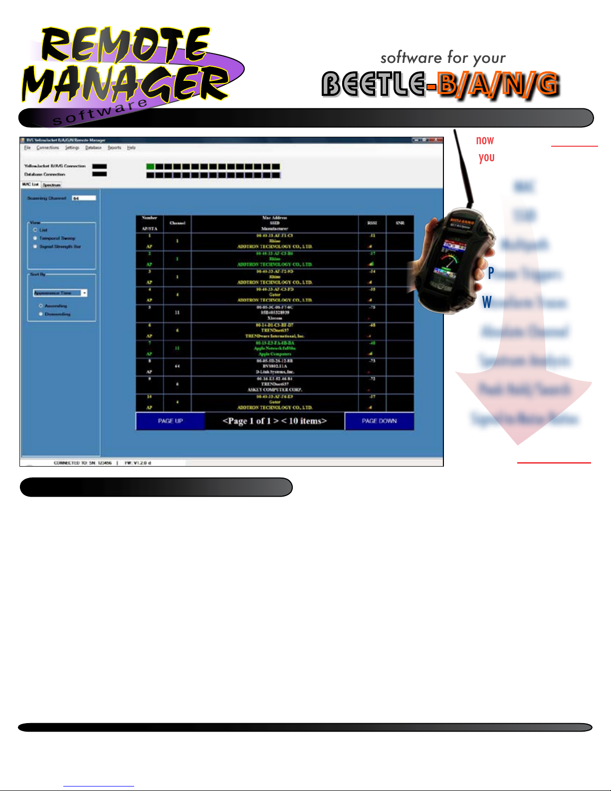
802.11b/a/n/g Remote Monitoring Software
BEETLE-
B/A/N/G
now you can see everything
your Beetle® BANG sees...
MAC
SSID
Multipath
Power Triggers
Waveform Traces
Absolute Channel
Spectrum Analysis
Features
• Controls Beetle B/A/N/G remotely from any RJ-45 connection
• Monitor your network from anywhere - home and ofce.
• Data collected in real-time and stored in a relational database*
• Create comprehensive reports from your measured network data
• Export reports to PDF® and MS Excel® formats
• Collect spectrum data from the RF environment
• Collect packet data parameters on such as MAC, SSID, Channel
• Data reports over various time periods for temporal overview of your network
• Software includes ethernet receiver dongle and cable
Peak Hold/Search
Signal-to-Noise Ratios
...from anywhere
Beetle® B/A/N/G Remote Manager™ software is a
data monitoring & reporting application that connects
to any Beetle® B/A/N/G through a standard 10/100
ethernet connection. With Remote Manager™, users
can control what wireless data is to be collected via
the Beetle® B/A/N/G receiver and store that data in a
relational database* for future retreival and analysis.
Remote Manager™ allows users to scan the RF spec-
trum for packets and interference over time creating
a network footprint of usage to find out who’s in your
network airspace with or without authorization. Remote
Manager™ even creates comprehensive PDF or MS
Excel reports for an IT manager’s overview. All of this
can be accomplished from anywhere in the world; all
you need is access to an ethernet connection to place
your Beetle® B/A/N/G receiver.
OPTIONAL SOFTWARE AVAILABLE FOR YOUR Beetle-B/A/N/G
Page 14
Beetle-BANG Data Logger iPAQ Windows Mobile Software
Introduction
The Beetle-BANG Receiver (802.11B/A/N/G) is a precision hand-held Wi-Fi packet
demodulator and optimizer. Data is displayed by Beetle-BANG software running on an
iPAQ. This iPAQ is connected to the BANG via a serial cable. The BANG has several
features to detect packets on or off the user’s network.
802.11b, 802.11g, 802.11n and 802.11a are demodulated by the BANG receiver and
displayed accordingly by the iPAQ software (BANG Controller).
Installation of Software
The BANG software is pre-installed on iPAQ computers purchased from BVS. A
completely depleted iPAQ battery will erase the software. See re-installation of
software in the troubleshooting section of this manual.
For users who are using their own iPAQ, follow the CD or SD card installation
instructions in the troubleshooting section of this manual to install the BANG software.
Getting Started
1. Power your BANG receiver and iPAQ as described in the “starting-up your
BANG” section of the manual.
2. Tap the Start button on the iPAQ.
3. Tap on the “Programs” folder.
4. Tap on the “BANG” icon.
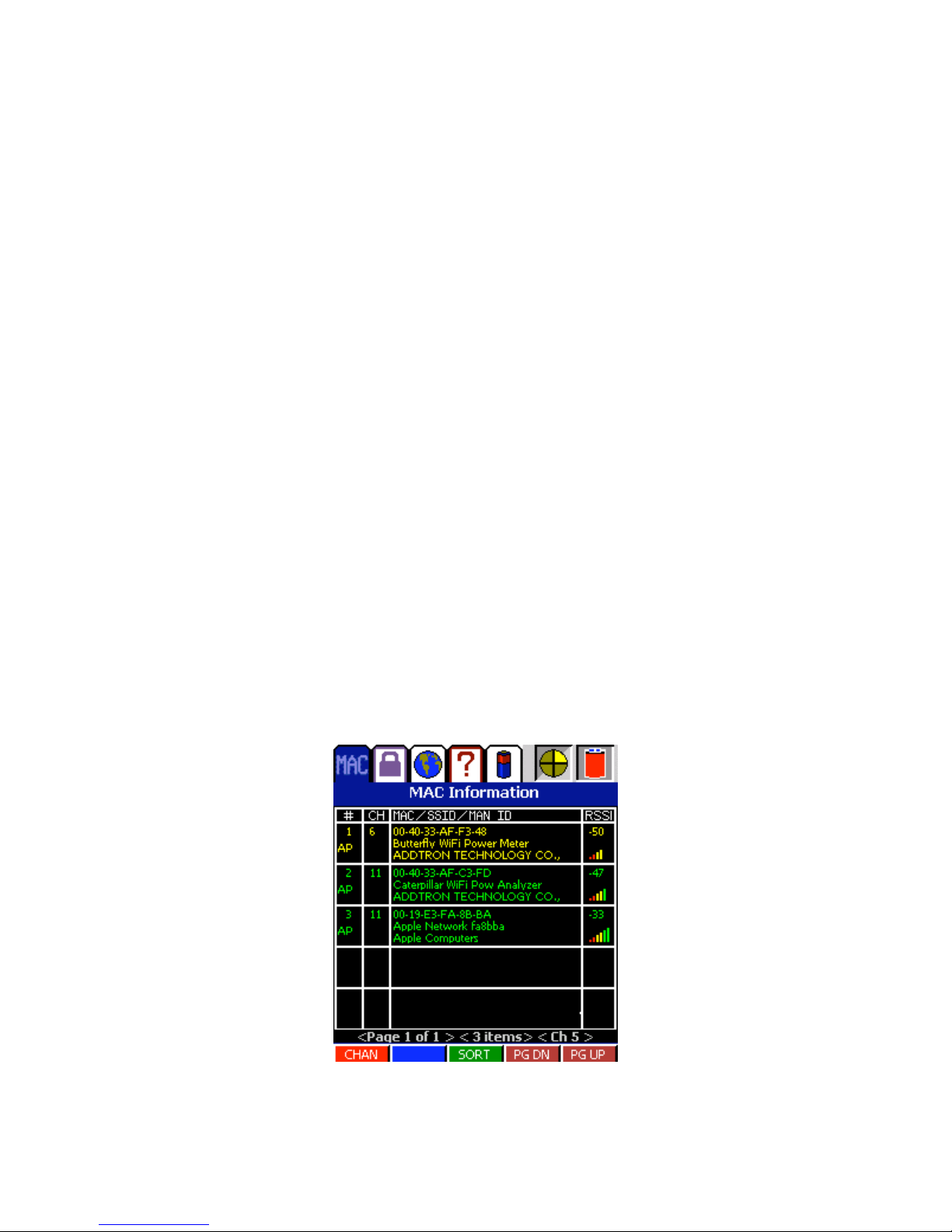
5. The MAC list display will appear initially and will scan the 2.4GHz channels by
default.
BANG CONTROLLER DISPLAY AT STARTUP
13
Page 15
Quick Tour
The BANG Controller has a tab control menu on the top of the display which separates
the functionality into main sections. These are:
1. Packet Processing-This section contains data relating to processing 802.11
packets. Information such as MAC address, SSID, channel, RSSI and SNR
(Signal To Noise ratio) information are displayed.
2. GPS-This is the area where global positioning information is displayed.
3. System Information-Information such as serial number, firmware version, and
frequency bands are displayed here.
4. Power Profile -Information on battery life, voltage, and power source.
Next to the tabs are two indicators. The first is a yellow section which spins in a circle.
This indicates that the software is functioning. Sometimes (for example in trigger
mode) data will not update at a constant rate. This circle shows that the software has
not frozen and is simply waiting for data.
The second indicator is for power. If a plug is shown, the BANG is on external power. If
a battery is shown, the unit is operating on batteries and a percentage remaining will
be displayed.
BANG Toolbar Options
From left to right, the toolbar buttons perform the following functions:
LOG FILE
When this icon is pressed, the log file control panel will be displayed. Use this control
panel to choose a log file, start and stop recording. Press the icon again to remove the
control panel. Log files can be used to post-process data with the PC Viewer utility.
SNAPSHOT
When the camera icon is pressed from the toolbar at the bottom of the screen, a
snapshot of the
currently viewable display is taken. The snapshot is saved as a BMP format picture for
viewing at a later time or for importing into documents and reports. As an example, the
images of the BANG screens shown in this section of the manual were saved
using this option.
BANG CONTROLLER TOOLBAR ICONS
PACKET PROCESSING
14
Page 16

The packet processing tab (MAC Information) puts the BANG in a mode to demodulate
802.11 B/A/N/G packets. The packets are separated by MAC address and put into a
list. Each item in the list can be selected. This will lead to another series of screens for
detailed analysis on the individual MAC address.
MAC LIST
The MAC list by default is populated as the different addresses arrive. The MAC
addresses will only show in the list if it can be proven that the channel it is seen on is
the channel it is transmitting from. This is so the correct RSSI value is shown. If the
information was shown while it was off-channel, then the RSSI value would appear
lower.
Each list item displays the following: Item number,whether it is an AP or not, channel
number, MAC address, SSID, Manufacturer's ID, and RSSI value. The color of the
information will vary depending on the strength of the signal. Green would be a
stronger signal and red would be a weaker signal. There are also bars (as a phone
would display) to show signal strength. These are located under the RSSI value.
There is a series of buttons under the list. These buttons are explained in the following
paragraphs.
CHANNEL SELECTION
Pressing the 'CHAN' button at the bottom of the MAC list, a dialog appears with
choices for channels to scan. Entire bands can be selected or deselected, as well as
single channels.
LIST SORTING
The MAC list can be sorted by pressing the SORT button at the bottom of the list. The
list can be sorted by:
1. Appearance Time – When a new MAC address shows up, it goes to the end of
the list.
2. MAC Address – Alphabetically by MAC address.
3. RSSI – Strongest signals go to the top of the list.
4. SSID – Alphabetically by SSID.
5. Channel – By channel number
Just choose the appropriate radio button and press 'OK'.
PAGE DOWN
Loads the next (up to) 5 items in the list.
PAGE UP
Loads the previous 5 items in the list.
15
Page 17
INDIVIDUAL MAC
When an individual MAC is chosen by tapping on its entry in the list, a set of screens
become available. The first screen is the multipath screen. All of the screens are
described below.
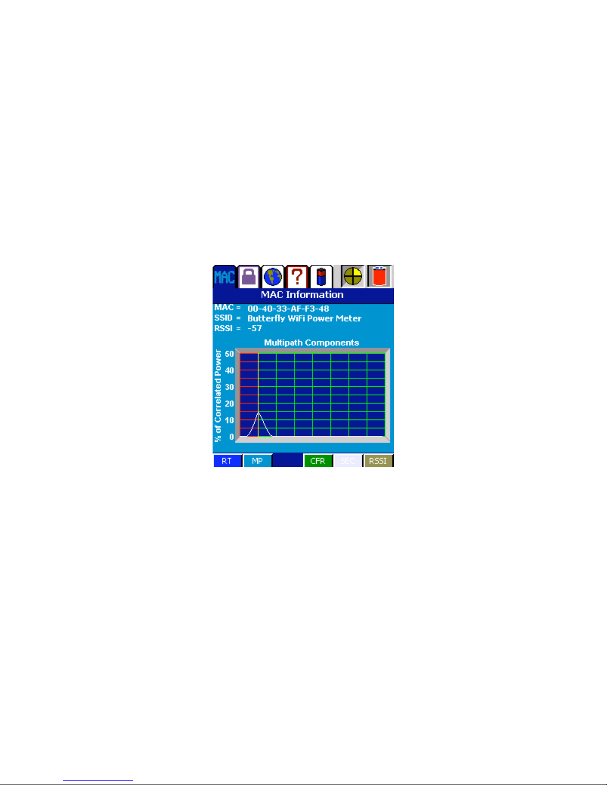
MULTIPATH
The multipath screen is chosen by pressing the 'MP' button. It also comes up by default
after choosing the MAC from the list. The screen shows a ratio of correlated power
versuse time.
BANG CONTROLLER MULTIPATH
16
Page 18
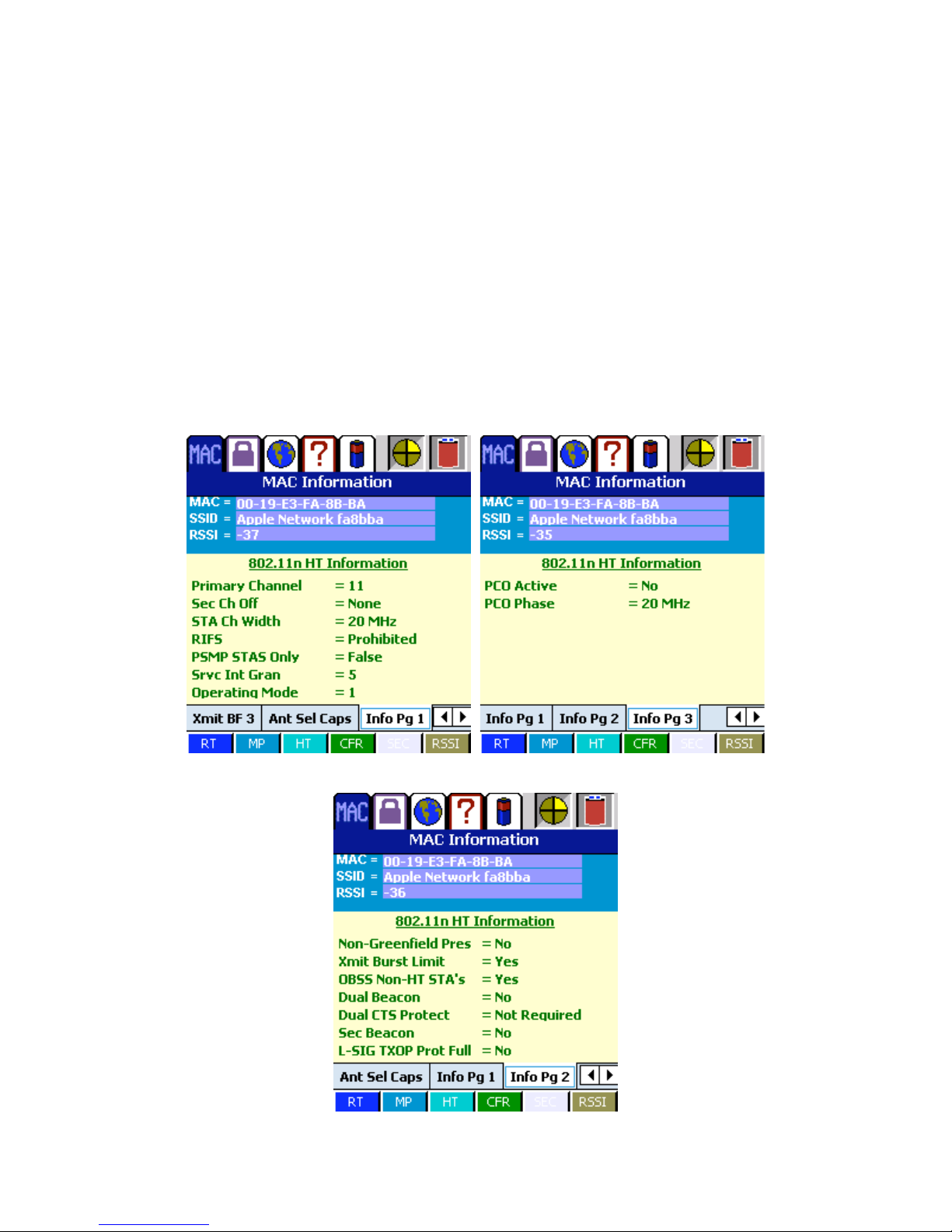
HIGH THROUGHPUT (802.11n)
The HT (High Throughput) screen will display high throughput data if the access
point/client is 802.11n capable and transmitting the high throughput information
elements.
The data is a series of tabs. The first tabs are high throughput capabilities such as
information about the 40 MHz mode. The next set are transmitter beamforming
capabilities. This is followed by antenna selection capabilities and finally other data
such as channel information.
The data on this screen is not valid on a non-802.11n access point.
17
Page 19
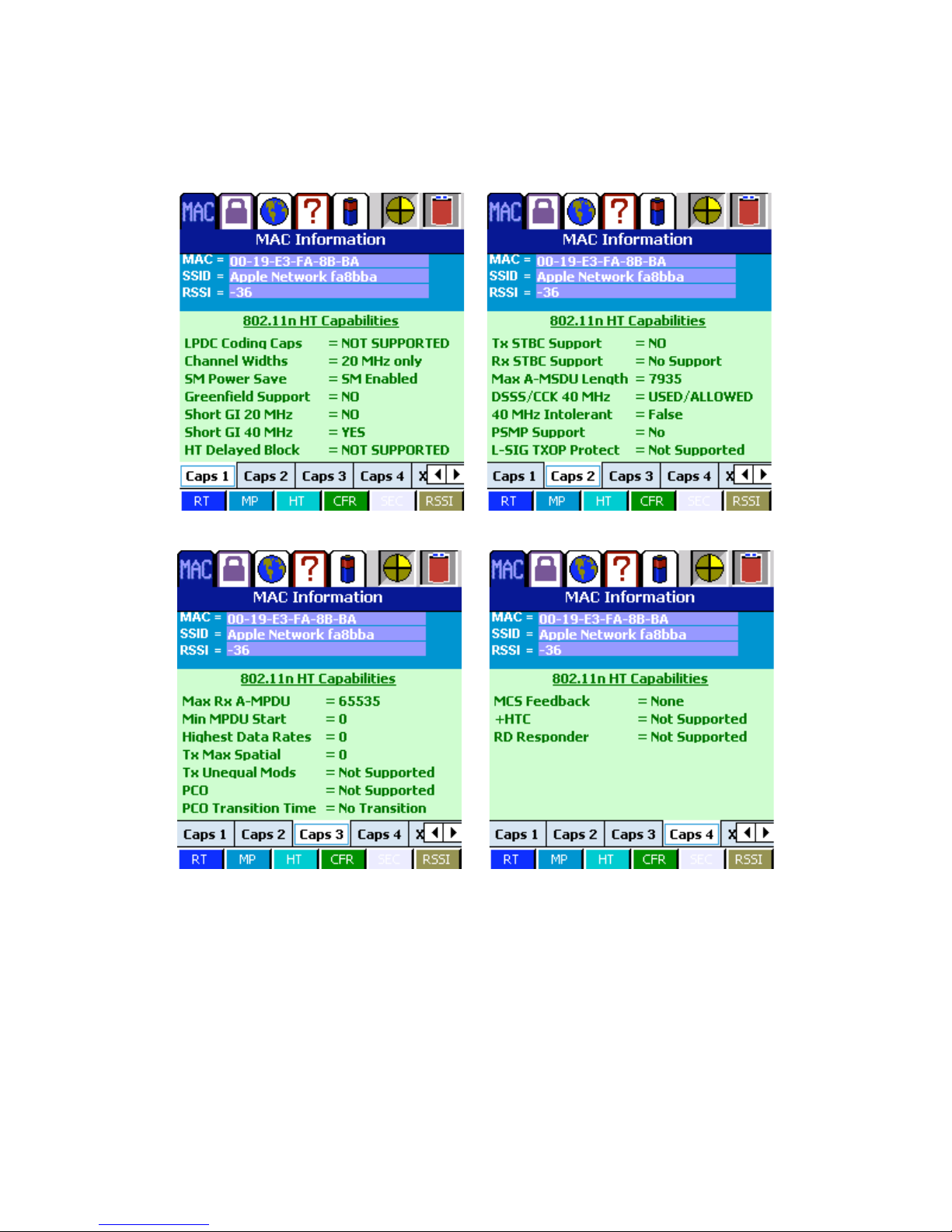
802.11 INFORMATION
802.11N HIGH THROUGHPUT CAPABILITIES
18
Page 20
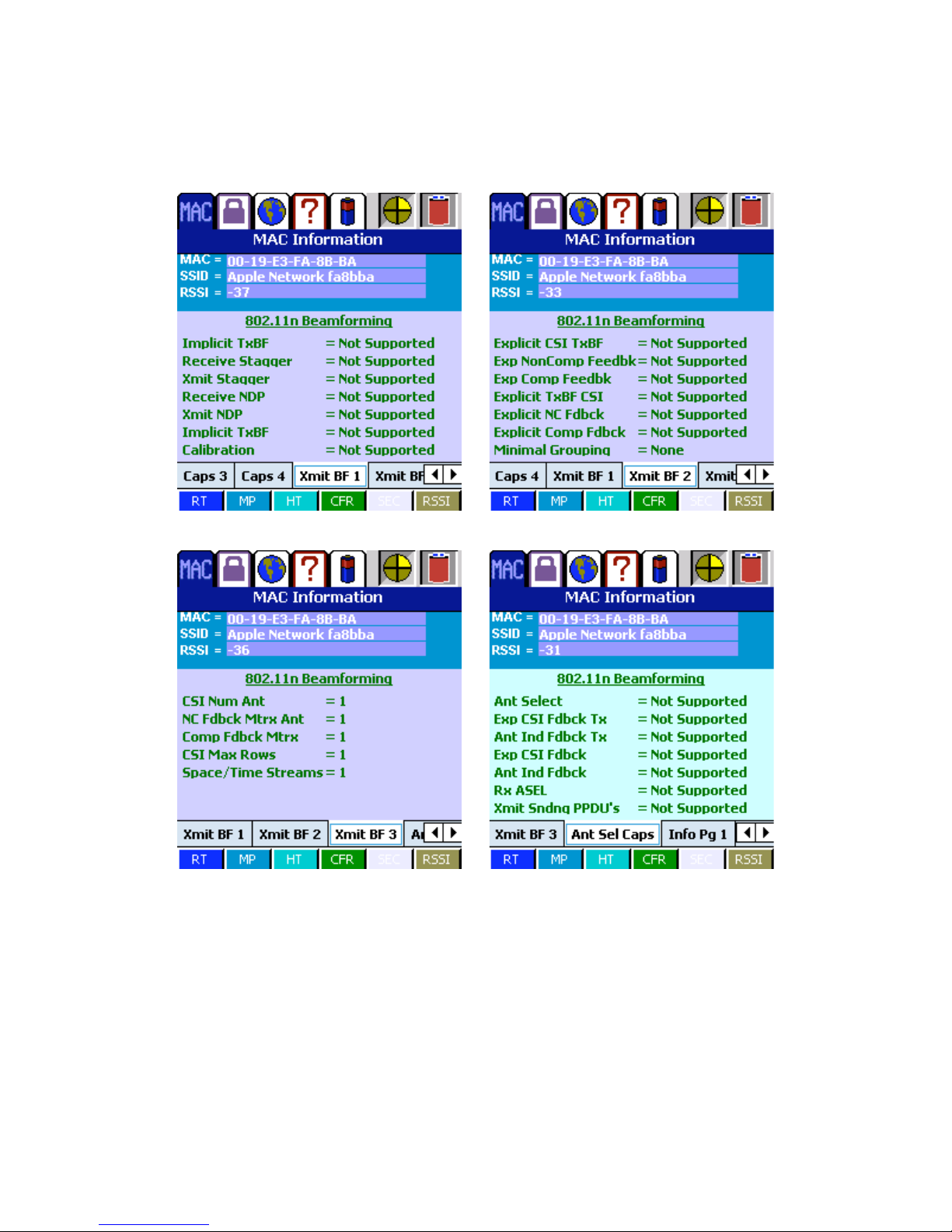
802.11N BEAMFORMING CAPABILITIES
19
Page 21
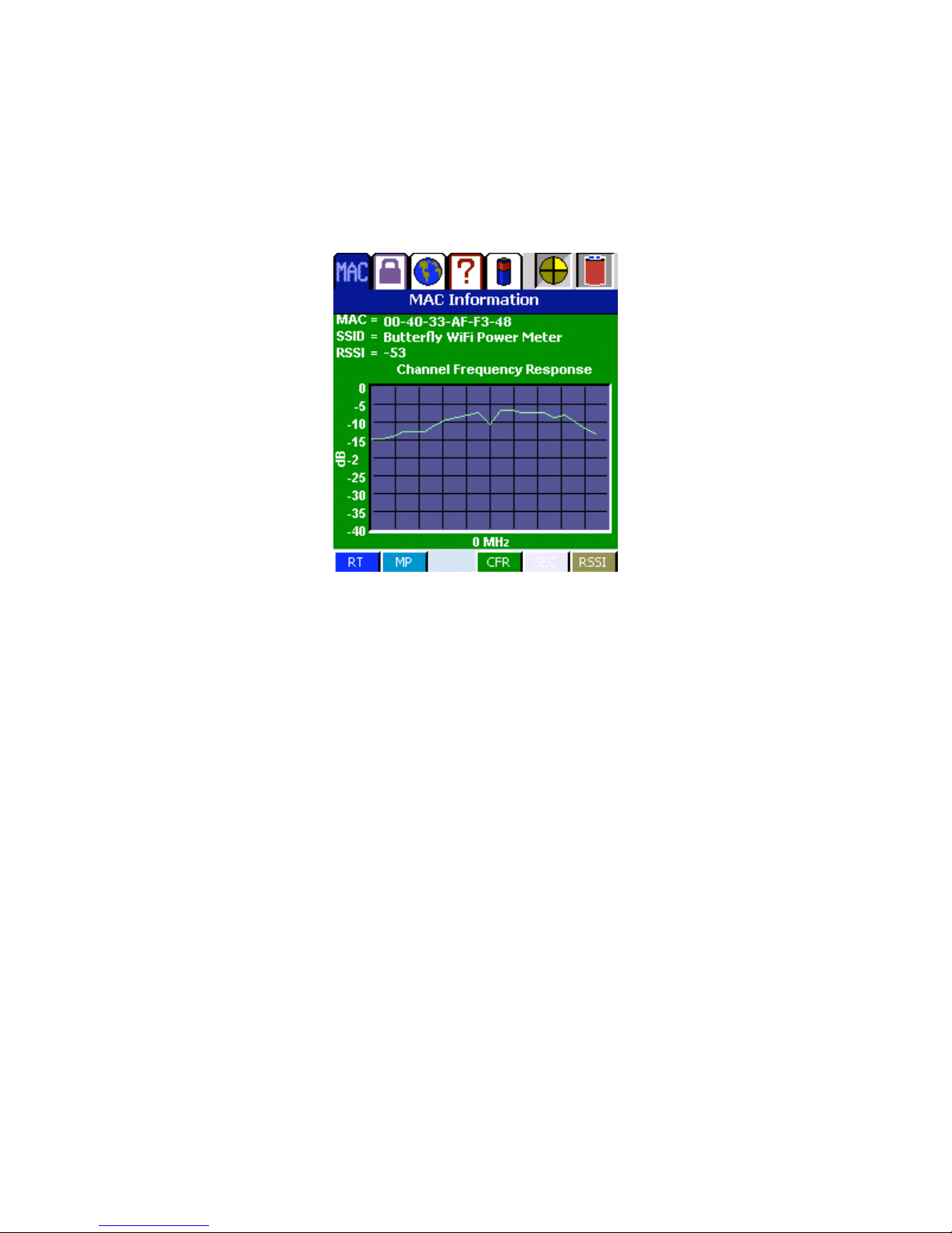
CHANNEL FREQUENCY RESPONSE
The channel frequency response screen shows the frequency response for the MAC in
question. The plot is signal strength versus frequency.
BANG CONTROLLER CHANNEL FREQUENCY RESPONSE
20
Page 22
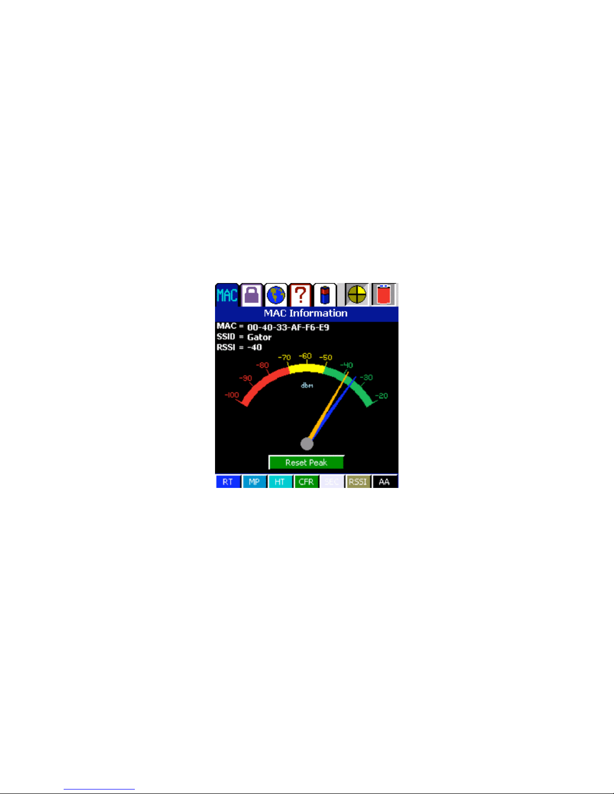
WISP ANTENNA ALIGNMENT
By clicking on the 'AA' button, a gauge will display. This gauge shows the current RSSI
value (yellow) along with the peak value (blue) in dBm. The peak indicator can be
reset by pressing the “Reset Peak” button.
By connecting a direction-finding antenna to the YBAG, this gauge will assist in
locating an access point. Simply change direction and watch the gauge. The peak
indicator will mark the strongest signal received. By turning the unit until the current
indicator approaches the peak indicator, the direction of the incoming signal can be
located.
Antenna Alignment Screen
21
Page 23
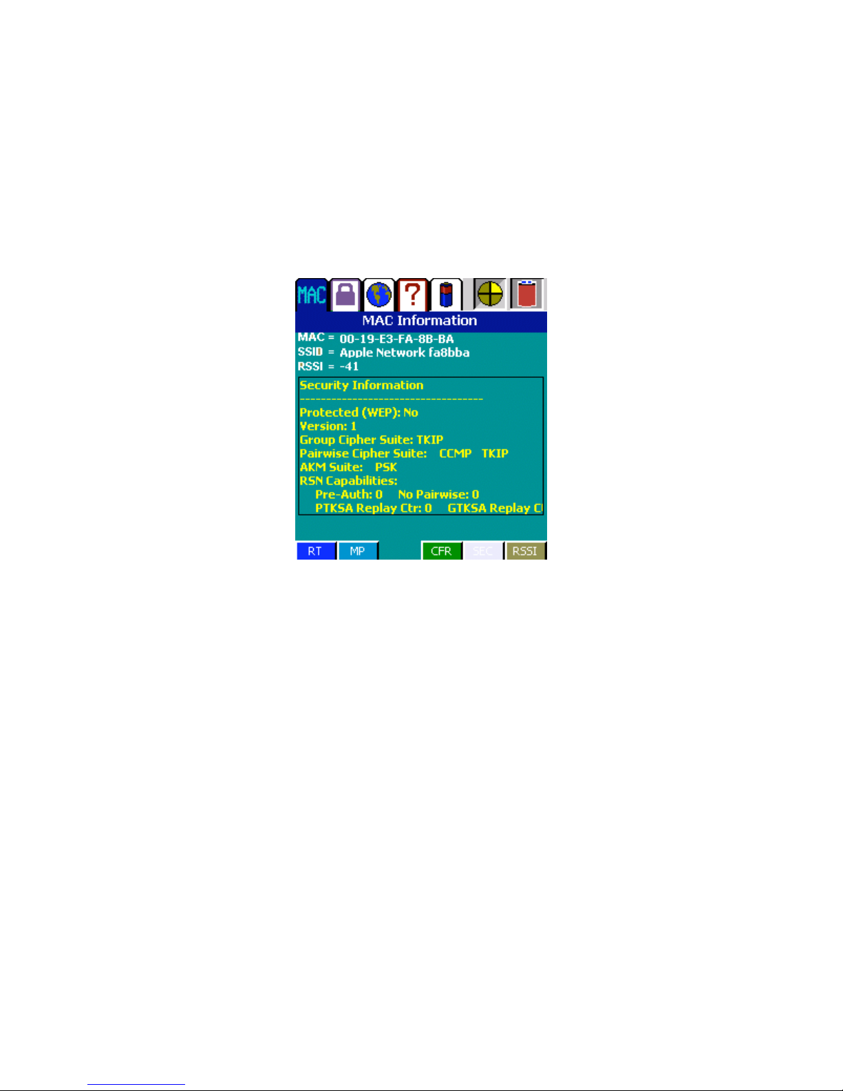
SECURITY
The security screen shows any security information that can be ascertained from the
packets for this MAC address. Information on security types such as WEP,TKIP,CCMP,
etc. may be shown.
BANG CONTROLLER SECURITY INFORMATION
22
Page 24
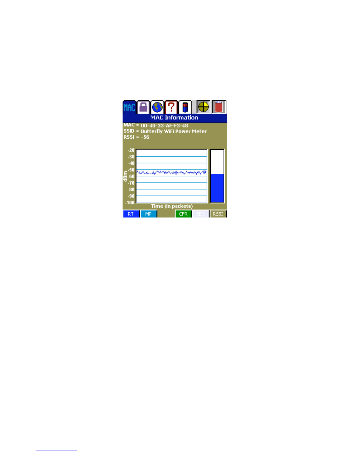
RSSI OVER TIME
The RSSI over time screen simply shows the RSSI values of packets coming in for the
selected MAC address. If the update stops, that means there are no packets currently
arriving from that MAC address.
BANG CONTROLLER RSSI OVER TIME
23
Page 25

SECURITY (AUTHORIZED/UNAUTHORIZED LISTS)
By pressing the tab with the lock, a security/authorization screen will appear.
The security screen allows for entering and maintaining of authorized and
unauthorized access point lists. This is a feature that is used for determining if there
are rogue/hostile access points within striking distance of the network. Checking the
“Enable Security” checkbox enables the security feature.
Authorized List
The authorized list is a list that contains the MAC addresses of access points that are
authorized to broadcast in the area to be concerned. This list can be created one of
three ways. The first way is by entering MAC addresses in the topmost edit field on the
security screen. Then the “ADD” button is pressed to add the address to the list. The
next method is to retrieve a previously saved list or a list that has been created on a
PC or laptop.
The final method is by pressing the “Generate Authorized List” button. This may be
pressed after leaving the YBAG in the MAC list screen for a period where all access
points have been seen. All of these MAC addresses will be moved into the authorized
list. This list can be saved to RAM by pressing the “Save List” button. This list can be
cleared by pressing the “Clear” button next to the list box.
The input file format for the authorized and unauthorized MAC list is as follows:
It is an ASCII file separated by CR/LF’s. The first line is the number of authorized
addresses in the list. Then each MAC is on a separate line.
AUTH COUNT
AUTH MAC#1
AUTH MAC#2
.
.
.
AUTH MAC#N
UNAUTH COUNT
UNAUTH MAC#1
UNAUTH MAC#2
.
.
.
UNAUTH MAC#N
After creating this file, it may be imported by using the ‘Retrieve List’ option.
24
Page 26
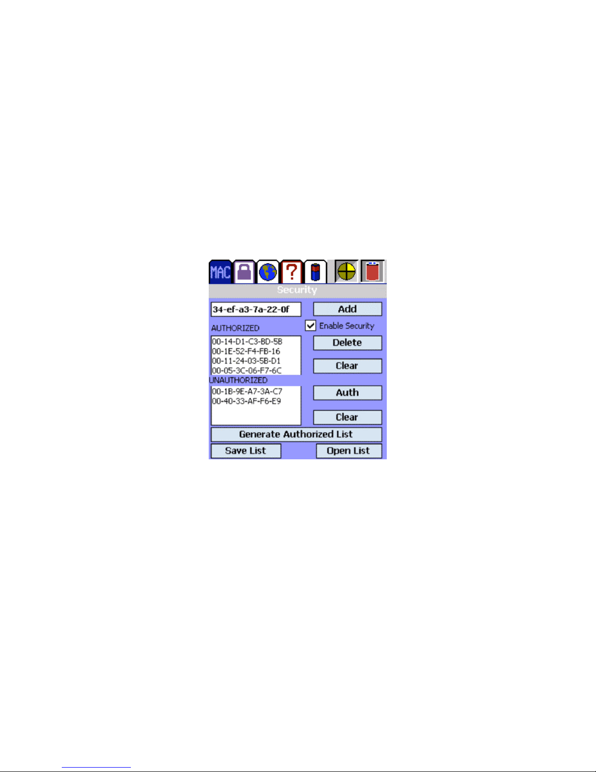
Unauthorized List
The unauthorized list is populated when the security feature is turned on. Any MAC
addresses seen and demodulated by the receiver which are not in the current
authorized list will be flagged and inserted into the unauthorized MAC address list.
Items in this list can be saved or retrieved to/from RAM along with the authorized list by
pressing the “Save List” or “Retrieve List” buttons. If the MAC addresses in the
unauthorized list are wished to be authorized, simply select the entry in the list box and
press the “Auth” button. This list can be cleared by pressing the “Clear” button next to
the list box.
Authorization Screen
25
Page 27
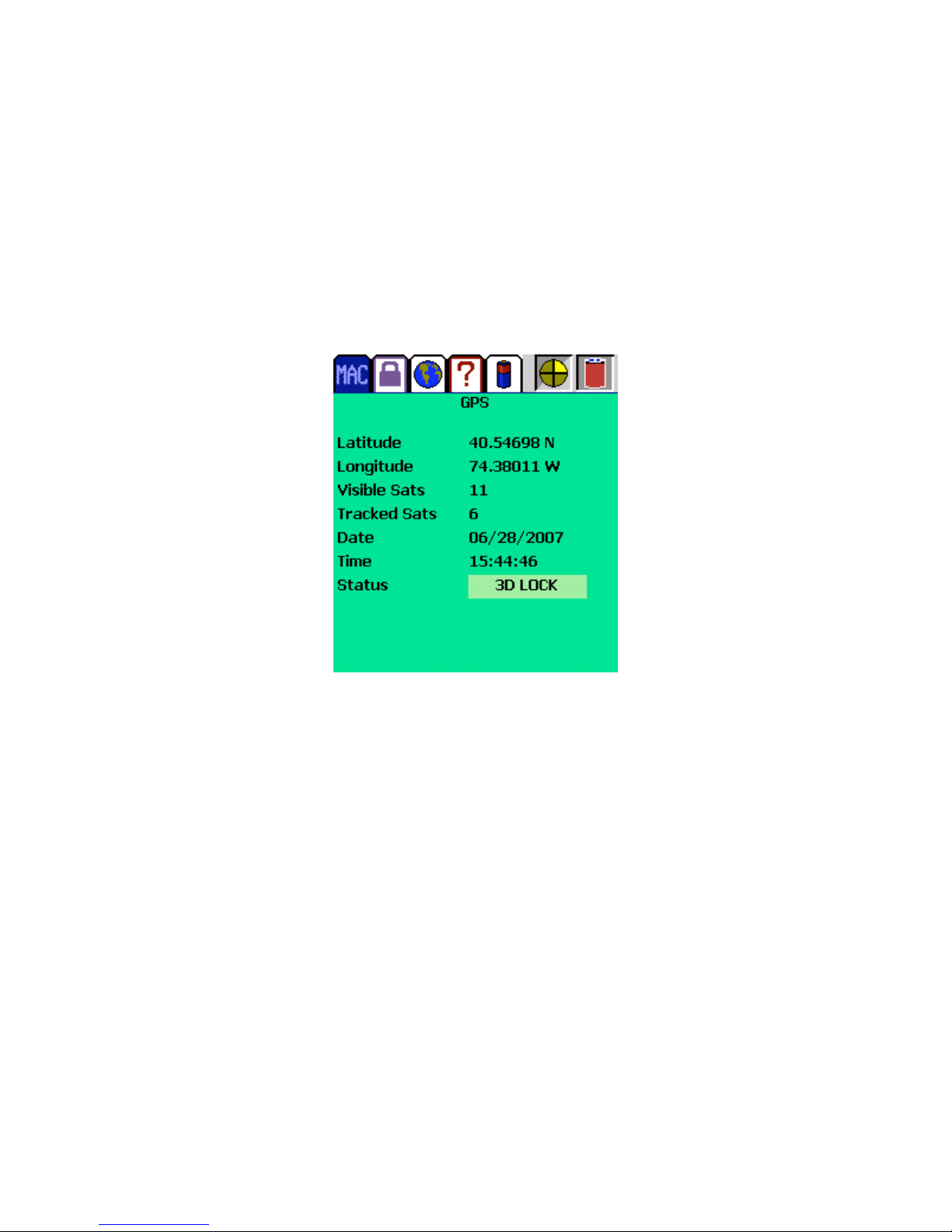
GPS Information
The GPS tab makes visible the GPS information screen. Information includes current
latitude and longitude, number of visible and tracked satellites, data and time, and
whether or not the receiver is locked. If the receiver is not locked, the status box will
become red. It will appear yellow if there is a 2 dimensional lock, and green if it has a 3
dimensional fix.
GPS DISPLAY
NOTE: The internal GPS receiver is activated as soon as the iPAQ application starts.
The first time the GPS receiver is used in a new location it may take up to 30 minutes to
achieve a lock. After that it should only take a few minutes. Make sure that the GPS
antenna is attached to the Beetle-BANG BANG GPS connector and threaded hand
tight.
The GPS antenna should be in an area that can see a majority of the sky. GPS
satellites are in orbit and change position. The antenna needs to be able to see a
number of these satellites at any time. If you are using the Beetle-BANG BANG in a
vehicle, it is best to mount the antenna on the roof. If you are walking outside, hold the
antenna flat to the sky and keep at least 1 foot from the Beetle-BANG.
26
Page 28
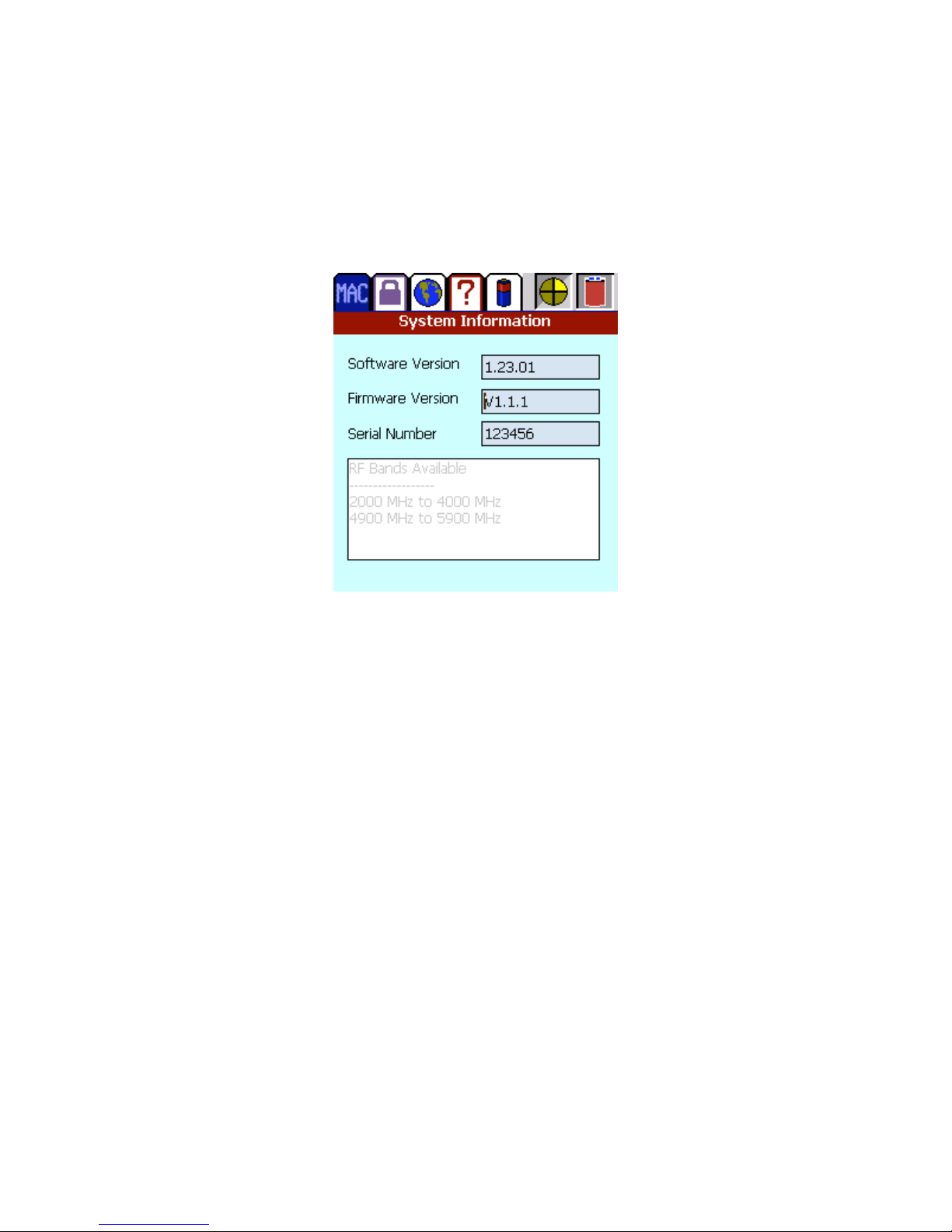
System Information
The system information tab shows the unit firmware version, serial number, and the
frequency ranges which are tunable.
SYSTEM INFORMATION DISPLAY
27
Page 29
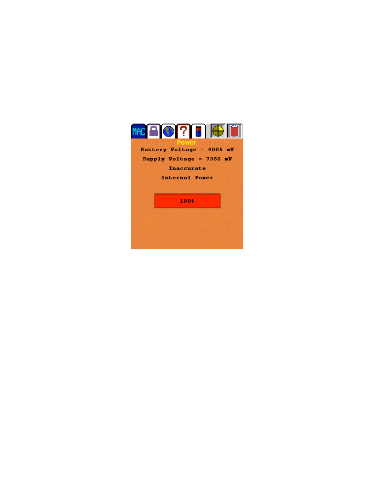
Power Profile
The power profile tab shows battery and supply voltage, internal/external source, and
percentage of battery life left. If this screen says “Inaccurate”, the battery has not been
trained (needs a charge/discharge cycle.)
POWER PROFILE DISPLAY
28
Page 30
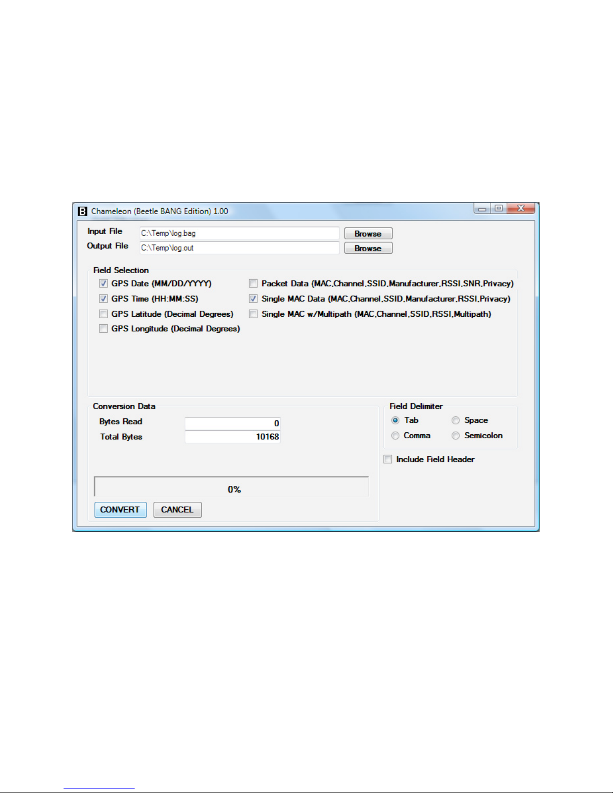
Chameleon Software for Beetle-BANG
Chameleon software allows users to gather collected Wi-Fi data and export it as
organized ASCII text or spreadsheets such as Excel. Chameleon is included on the
Beetle-BANG SD installer card and runs under Windows XP on a laptop or desktop
PC.
29
Chameleon Screen
 Loading...