

Page 1
Page 1 of 12
Beech Electric Oven Manual_R5.doc
2012-05-08 (C)
Electric Stone Hearth Oven
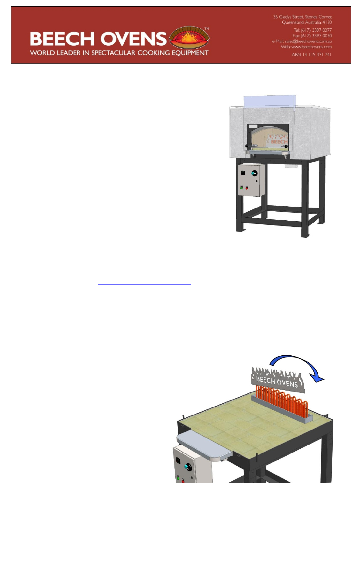
The Beech Ovens electric Stone Hearth oven has been
developed to include an “in-floor” electric element and a
smooth action, counterweighted glass sliding door. The
benefits of the in-floor e lement are that it is easily removed
for cleaning, maintenance, inspection and replacement and
can potentially be replaced with a gas burner at a later date if
required.
The element cover panel i s designe d to ref lect the majority of
the radiated heat from the element to prevent excessive heat
being radiated onto the food product. Without this panel the
floor temperature directly in front of the element would be
too hot to cook when the rest of the oven is at normal
operating temperature.
The electric control sys tem is a simple touch button control system with a number of features for
monitorin g and controlli ng the oven, and el ement temperatu re. It has built in m echanism to pr otect
the element fr om ov er h ea tin g to p r olo n g th e li fe of the el em en t. Con t ac t Be ech Ov ens te chn i ca l sta ff
for more information – [email protected]
Oven Assembly
The oven is delivered in 2 main sections – the top and base. For the assembly of the oven
components and general installation guidelines, refer to the Installation and Operation Manual.
The top section of the oven is delivered with the glass sliding door attached. The door is fully
fitted and requires no installation apart from unpacking.
NOTE:
Be very careful when unpacking
the oven not to damage the glass sliding
door.
The element cover panel can be fitted before
or after the oven top is assembled. To fit the
cover panel, slip it onto the main burner
shroud, starting from one end and “folding”
onto the slot.
Page 2
Technical Specifications
22Kw – (2 x 700 Elements)
Power supply should be;
3 phase,
32 Amps per
4 core cable consisting of 3 actives and 1 earth.
Beech Electric Oven Manual_R5.doc
Page 2 of 12
2012-05-08 (C)
The specifications below refer onl y to Beech electric ovens . At time of publication, Beech electric
ovens are only available in the following sizes; REC0700, REC0850 and REC1250.
Model No:
REC0700
REC0850
REC1250
Element Rating (Kw)
10Kw - (1 x 500 Element)
11Kw – (1 x 700 Element)
Amps (3 Phase)
20A per Phase
20A per Phase
32A per Phase
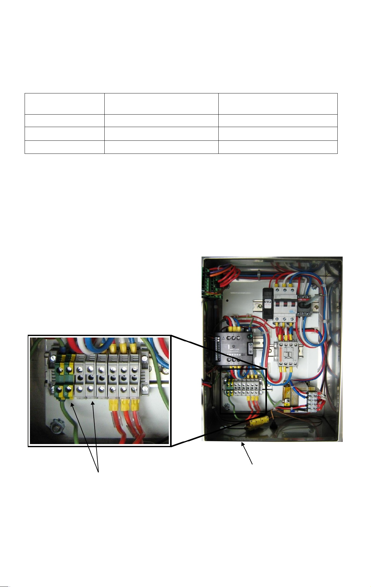
Electrical Connection
Ensure the power connection is carried out by a qualified electrician. The cable from the control
cabinet to the element is factory f itted and only mains power is required. The elements are rated for
approx 12Kw.
Control panel with door open
phase,
Main Power Supply in (3
x power – 1 x Earth)
Mains power supply
lead in here
Page 3
Electrical Operation
Beech Electric Oven Manual_R5.doc
Page 3 of 12
2012-05-08 (C)
Precautions with Electric Systems
To optimize the service life of the electrical element, all Beech El ectri ca l sy stem s are desi gned
to protect the electrical element from overheating. The maximum allowable temperature of the
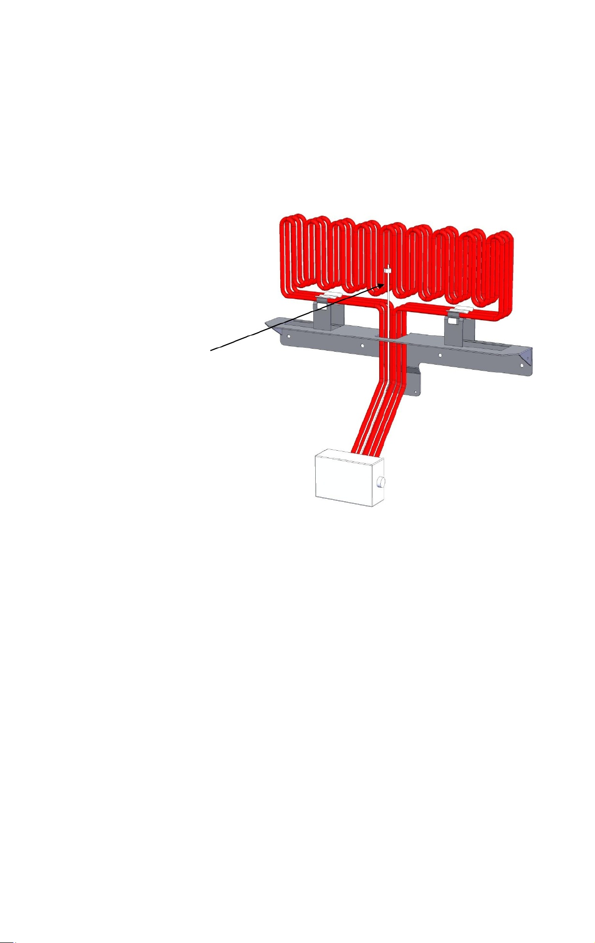
electric element coil is 750°C. The elements have an over-temperature probe fixed to the
element to measure and monitor the element sheath temperature.
Over-temperature Probe fixed
to element
The Control System protects the element from overheating in the following manner:
1.
The system main switch is turned on. The green light will turn on to indicate power is
supplied.
2.
The red indicator light w ill the n tur n on w he n the heating element is active.
3.
The red indicator light will howe ver turn off if the el ement should go over temperature.
4.
The on/off cycle is indicated on the controller output light 1 on the top right of the controller
display as well as the ramping function. This will cycle until the oven reaches the SV (set
value) on the controller.
5.
The maximum temperature se tting (SV) for the oven is 300°C.
Page 4
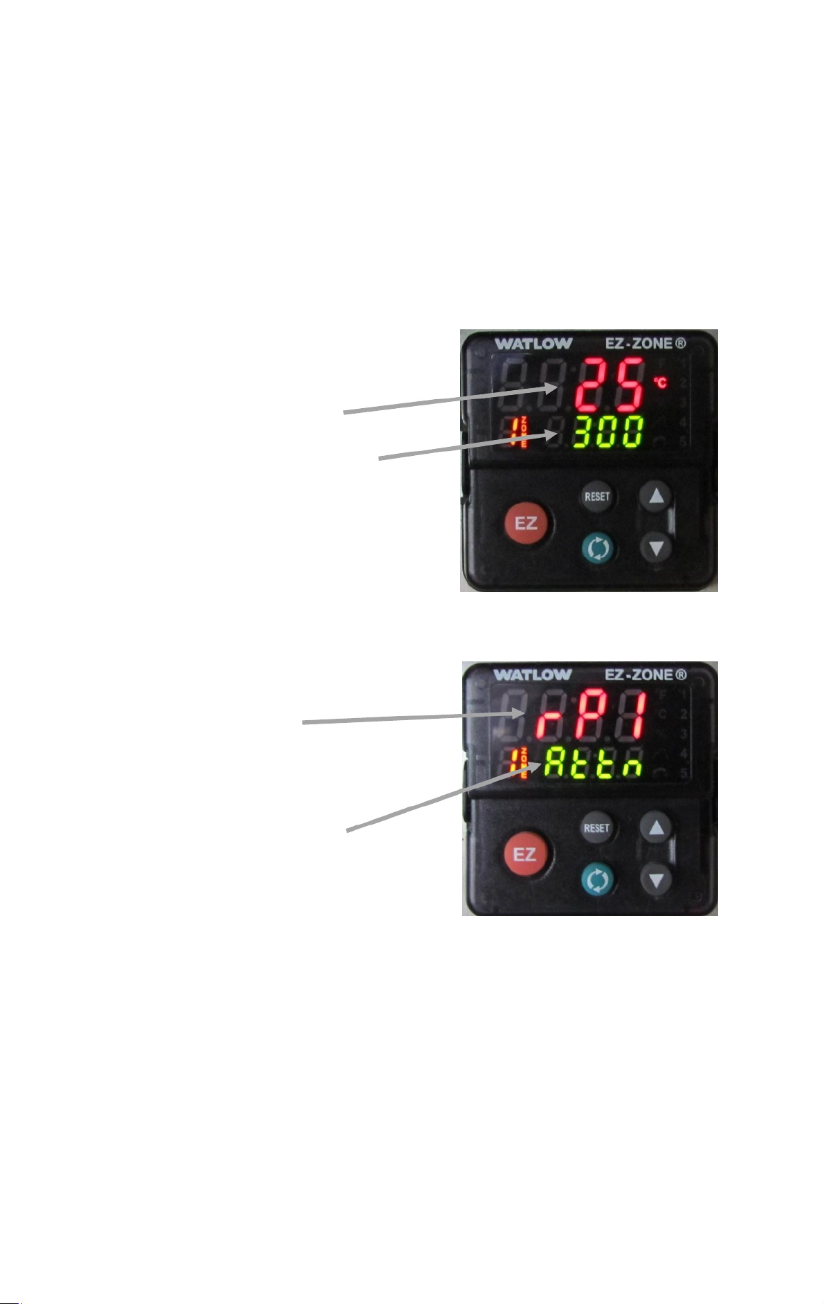
The control system incorporates a ramp-up timer into its program to ensure all temperature limits
Signalling “Ramp 1”
(Normal)
“Attention” alert
(Normal)
Current Temperature
Set (required) T em per ature
Beech Electric Oven Manual_R5.doc
Page 4 of 12
2012-05-08 (C)
are monitored & controlled to suit. The service life of the electrical element depends on how often
and how long it operates on maximum temperature.
The maxi mum setting for the oven tem perature is 300°C. The maximum over te mperatur e s e t t i n g
for the electrical element probe is 750°C.
NOTE: these settings cannot be altered.
controller screen will alternate between 2 screens during normal operation;
Screen 1
Screen 2:
: This shows the set temperature and the current temperature.
This shows that the digital controller is ramping to achieve the set temperature.
The digital
NOTE: Alternation between these 2 screens is normal.
When the oven starts from cold, this may take 8-10 hours the first time. After that, the heat up time
will be much shorter (up to 3 hours).
NOTE:
It is important to ensure the sliding door is down during all heat up periods and also when
the oven is turned off to retain heat.
Page 5
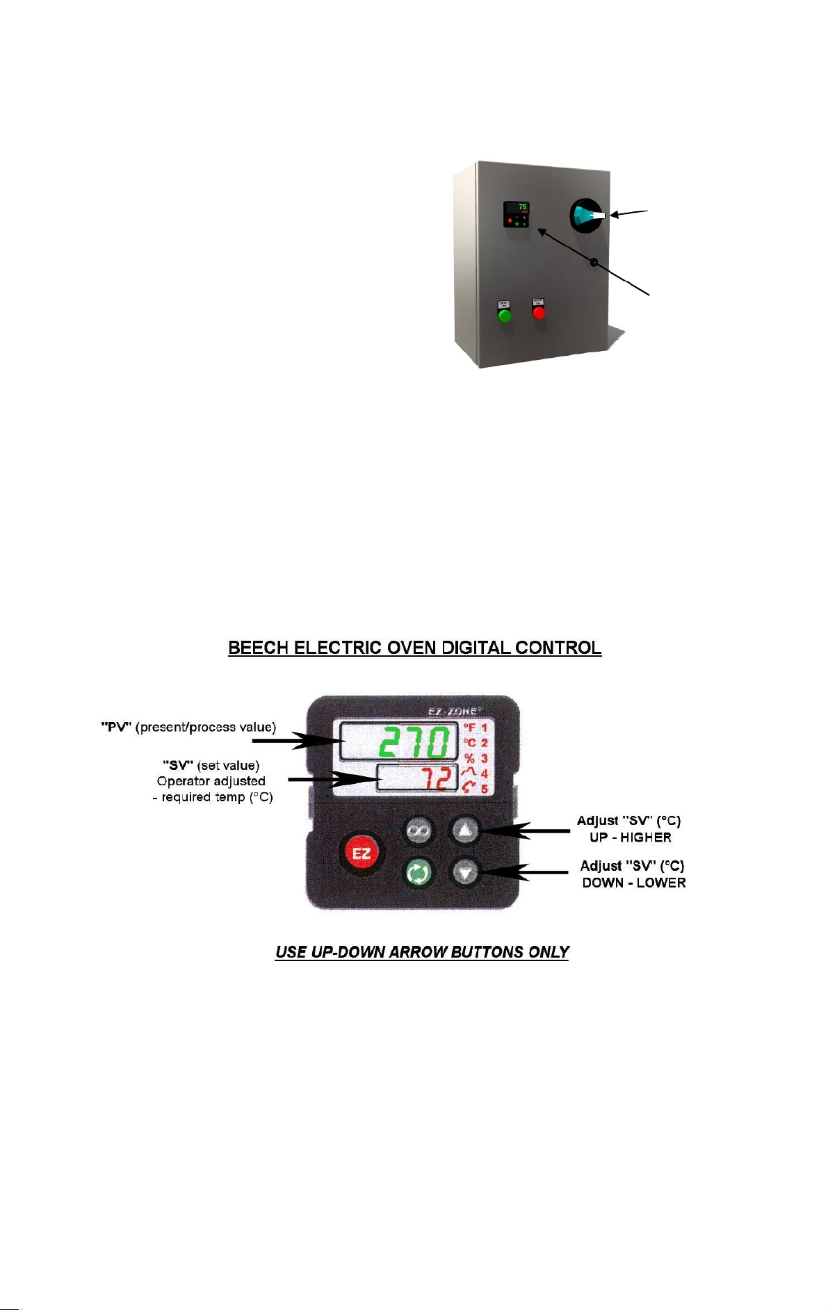
Electrical Ignition Summar y
Beech Electric Oven Manual_R5.doc
Page 5 of 12
2012-05-08 (C)
1.
Ensure the Exhaust fan / Canopy is ON.
Main ON / OFF Switch
2.
On the main control cabinet, turn the main
switch to ON. (The green light will turn on to
indicate that power is on)
Digital
Controller
(The r e d light will indicate if the heating element is
active, that is when ‘PV’ is lower than ‘SV’)
3.
The large display on the temperature controller will indicate the “P V” (Present Value) of the
oven temperature. This is the current temperature of the oven floor.
4.
The smaller display on the temperature controller will indicate the “SV” (Set Value) of the
oven temperature. This is the desired temperature of the oven floor. To adjust the “SV”
temperature, use the arrows on the right hand side up or down until the requi red temperature
is achieved.
5.
When cooking is finished for the day, turn “
OFF
” the main switch on the control cabinet
and close the sliding door to keep warm for the next day.
The Digital Temperature Controller has been pre-programmed to factory setting for “Hi & Lo”
limits. The program is locked into the controller. For access to this program, an authorized
technician should contact Beech Oven s.
Page 6
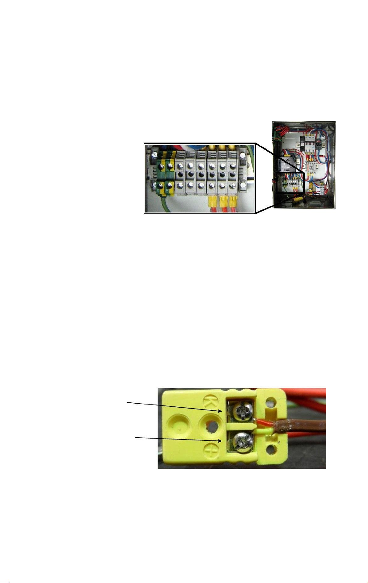
Electrical Ignition - Trouble shooting
Red wire is negative.
Yellow wire is positive.
1 2 3 4 5 6
Beech Electric Oven Manual_R5.doc
Page 6 of 12
2012-05-08 (C)
If the electrical system is not performing correctly, check the following:
1.
With the power turned off to the control panel, c heck the resistance (ohm) readings
across terminals 4, 5 & 6 in the control box. For singl e element syste ms, the y should
read as follows depending on the supply voltage:
440 Volt = 35 Ohms +/- 10%
415 Volt = 31 Ohms +/- 10%
400 Volt = 30 Ohms +/- 10%
380 Volt = 27 Ohms +/- 10%
NOTE:
For systems using 2 banks of heating elements, the readings should read
approximately half of th e settings above. (E.g. Range from 17. 5 ohms (440 V) to 13.5 ohm
(380 V) +/-10%)
If the readings are out of range, ensure all connections are tight a nd r e tes t. If the re is no
improvement, one of the 3 elements may be defective.
2.
Check the supply voltage readings across terminals 1, 2 & 3 in the control box. These
readings need to be within +/- 5% of the voltage required for this system. Check the data
label in the control box to verify correct vo ltage.
3.
Turn the power on to the control panel and check both thermocouples readings on the
digital controller show a positive reading and increase when power is on. If reading
negative, or if the temperature goes down instead of up, identify where the
thermocouple wires are incorrect on the yellow connectors and reverse the polarity.
(
NOTE:
The red wire is negative)
Page 7
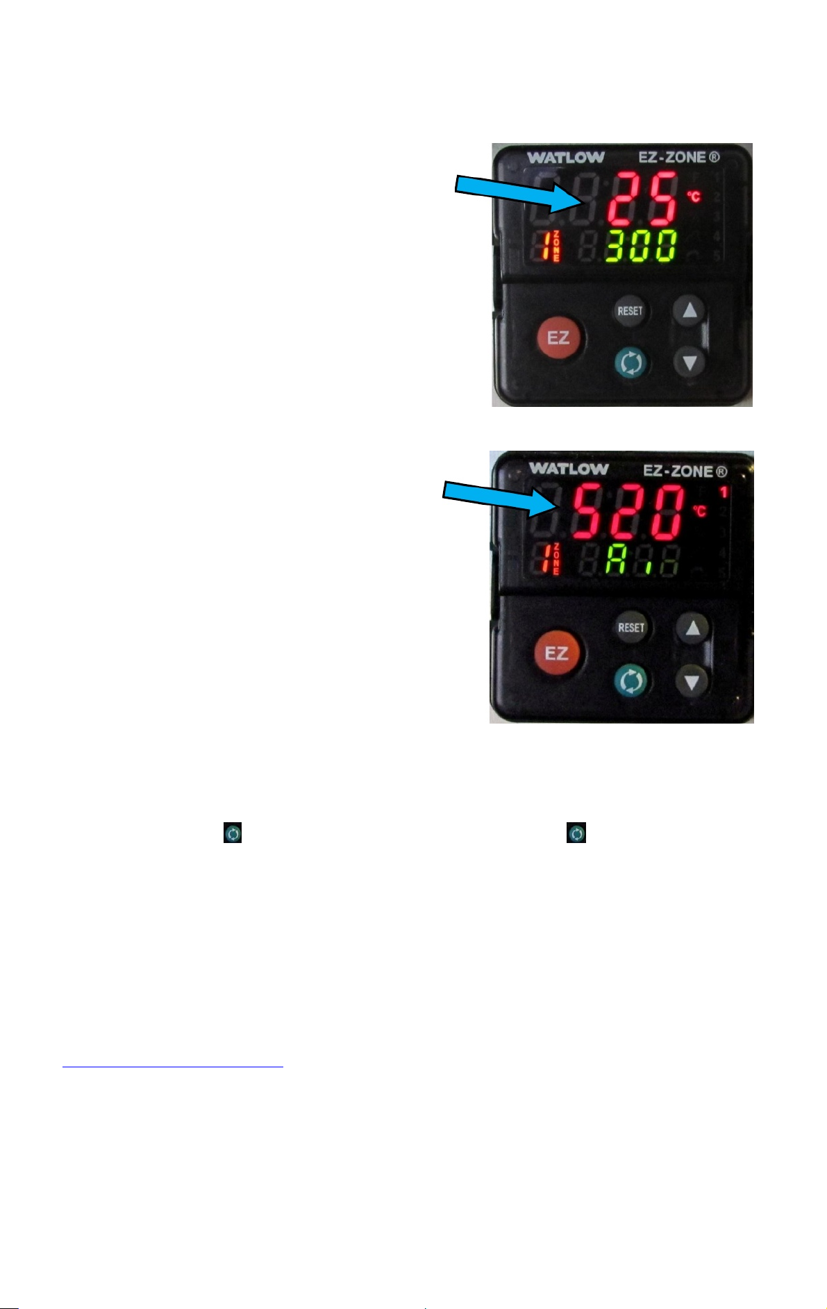
3.
Then push the button, then the down arrow once, then the button to displ a y the current
‘over temp’ reading shown above.
The ‘element over-temperature’ setting must also show a
positive number here.
(If a negative number is shown, or if the t emperature goes
down instead of up, reverse the polarity of the yellow
thermocouple connector as shown on previous page.)
For the oven temperatu re (PV) sett ing, this must show a
positive n umber here.
(E.g.
-25)
(If a negative number is shown, or if the t emperature goes
down instead of up, reverse the pola
thermocouple connector as shown on previous page.)
Beech Electric Oven Manual_R5.doc
Page 7 of 12
2012-05-08 (C)
Not
a minus symb ol.
rity of the yellow
Not
a minus symbol. (E.g. -520)
To access the “over temperature” screen above, refer t o the following procedure:
1.
Push and hold the up and down arrows (
2.
If done correctly, this will access the ‘operations’ menu.
4.
This must show a positive number here -
5.
To go back to the original screen, push the
appears.
▲▼
) together for several seconds.
NOT
a negative number.
RESET
button till the original screen
This trouble shooting process will identify if an electrical element is faulty, verify the supply
voltage is cor rect and uniform acr oss all phases, verify both thermoco uples are operati onal and
checks they are connected correctly.
These are the main i s s ues that occur with Beech Electri c Temperature Systems. For any
further troubleshooting enquiries, please contact our technical department:
[email protected] or Beech Ovens Head Office.
Page 8
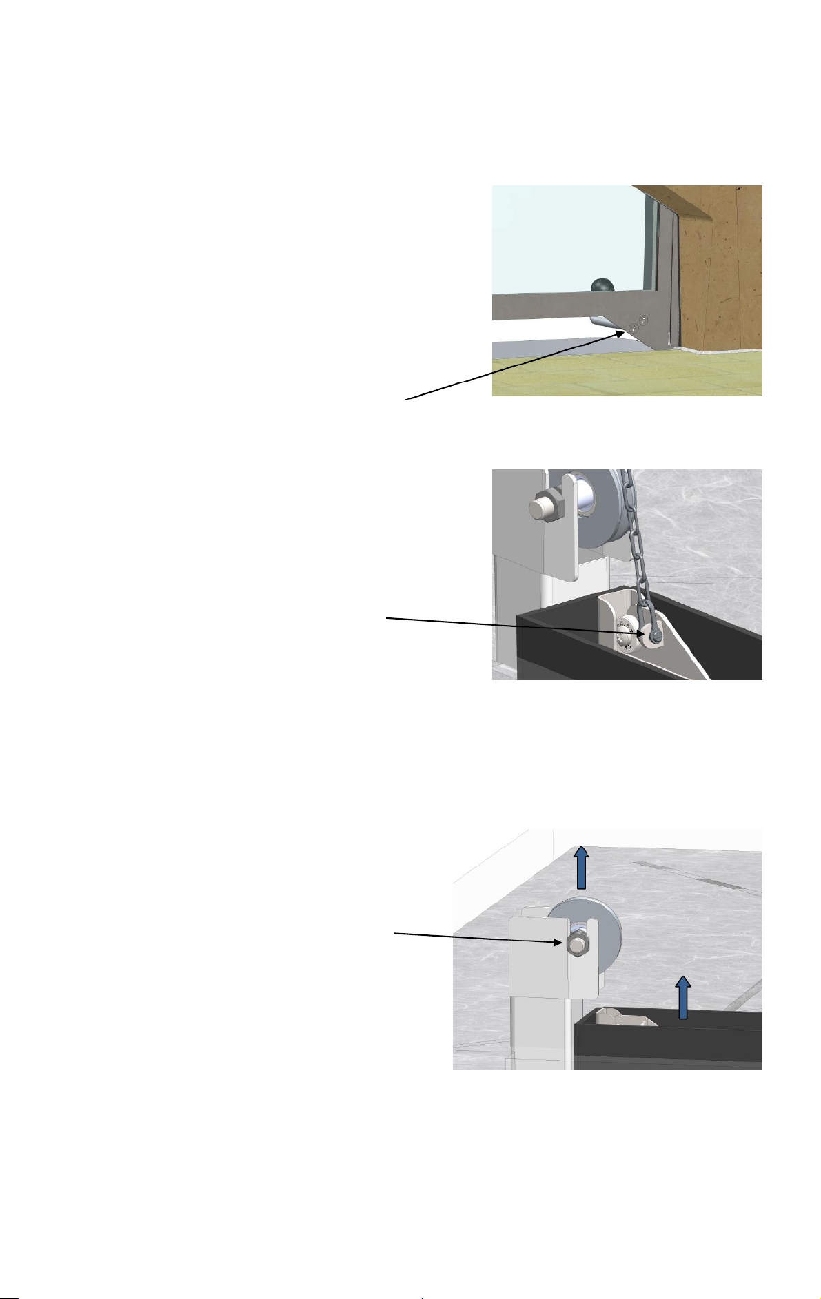
Sliding Door Replacement
Beech Electric Oven Manual_R5.doc
Page 8 of 12
2012-05-08 (C)
Should the glass slid ing door be damaged or broken at any
time, it can b e removed and replaced.
1. Loosen and remove the 2 screws holding the
handle in place.
2. Slide the window up until the latches holding the
: Make sure you retain the chain so it does not
fall down the counterweight tube.
Loosen and remove both
screws to remove handle
(Both sides)
cable can be accessed and removed.
NOTE
Loosen and remove “D”
shackle
(Both sides)
3. Remove the guide rollers and lift the glass door out of the spigot
Remove the guide rollers
and slide the door frame
out of the spigot (Both
sides)
Replace in reverse order.
Page 9
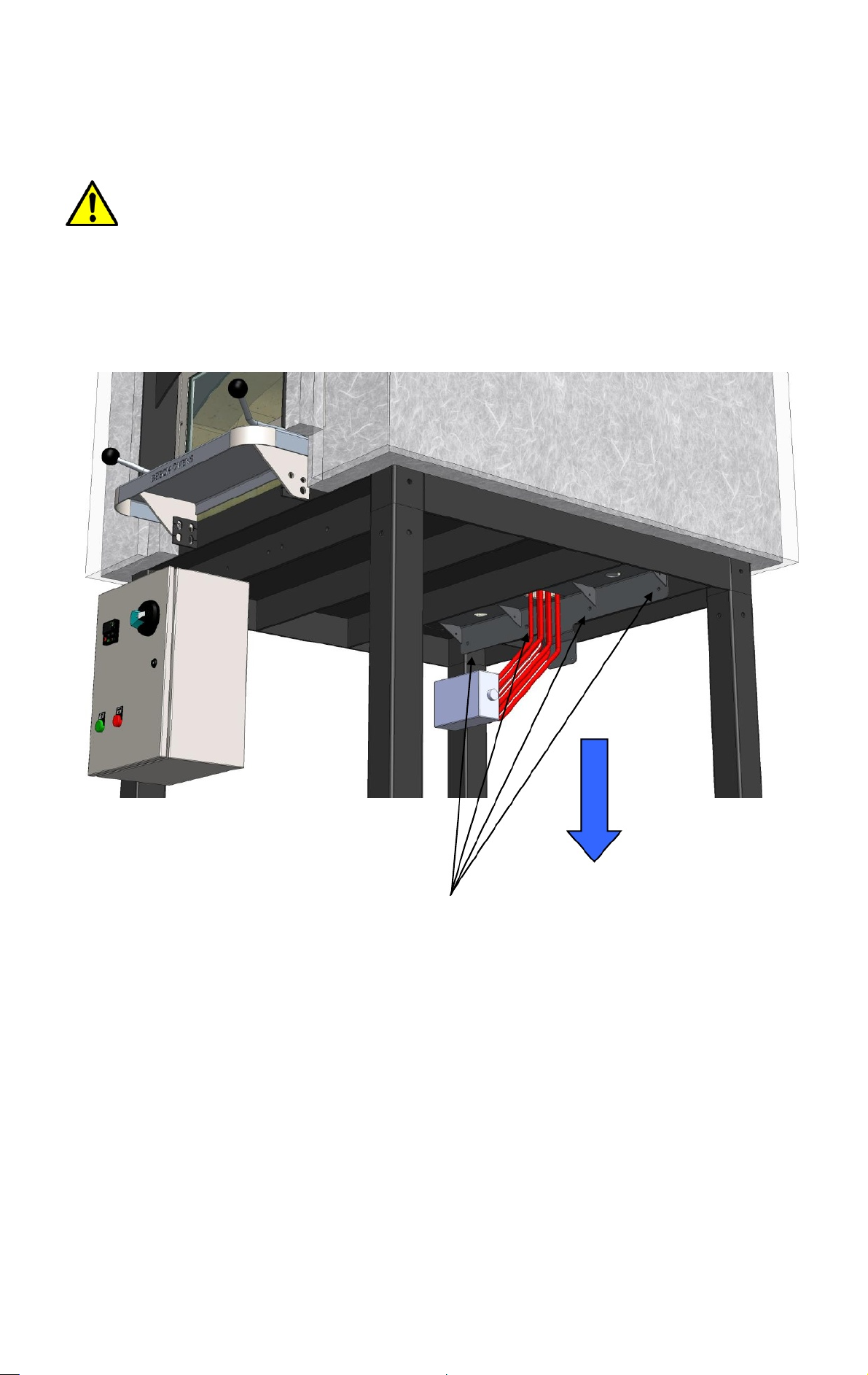
Element Replacement
ENSURE THE OVEN IS OFF AND THE ELEMENT IS COOL BEFORE ANY
ELEMENT REPAIRS. ALL ELECTRICAL WORK SHOULD BE DONE ONLY BY
LICENSED PROFFESSIONALS.
Beech Electric Oven Manual_R5.doc
Page 9 of 12
2012-05-08 (C)
Should the electric element need removing or replacing, simply loosen and remove the 4 bolts
holding the element support bracket in place. Lower the entire element assembly through the oven
floor.
Loosen and remove 4 bolts holding
element support assembly
Disconnect and remove the cables from the element junction box.
Assemble in reverse order.
Page 10
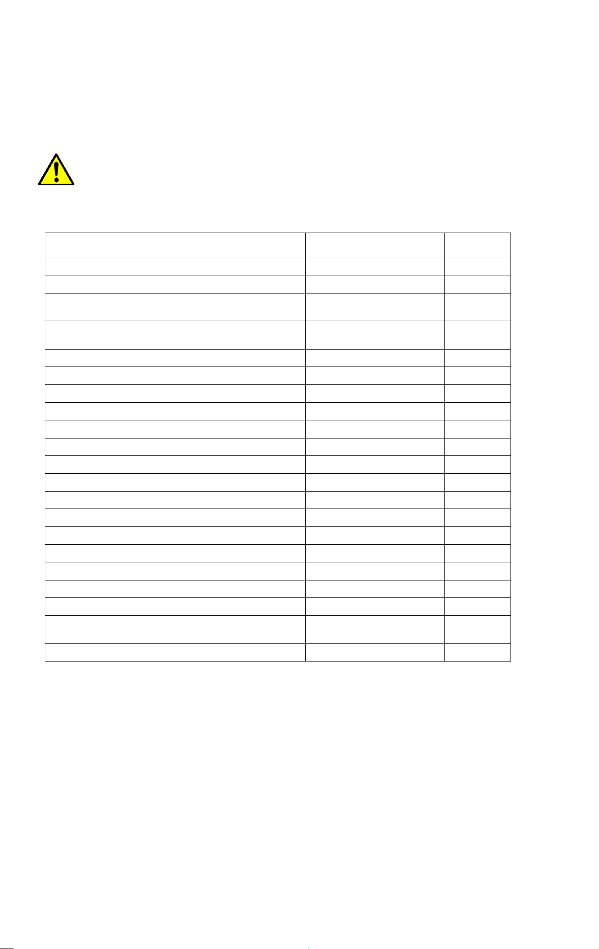
Electric System Spare Parts
Pilot Light Element Red
D7P-P4-PN3R
1
Legend Plate - Blank - Engraved " P OWER ON
"
Legend Plate - Blank - Engraved " HEATER ON
"
Contactor CA7-30-00 240 VAC
CA7-30-00-240VAC
1
Circuit Breaker 10KA 3P 25A
DTCB10325D
1
Terminal 24 Amp 2.5sqmm
V7-W3 4
T erminal 41 Amp 6sqmm
V7-W6 6
End Plate
V7-EB10
1
Earth Terminal 6sqmm
VUPE 4-6
2
Fuse holder - 32 Amp
NV32FW
2
Fuse BS88 - 10 Amp
NNS10 2
Transformer
(Voltage ???)
1
500 Element Set - 380/415/440V 9kW
1
Over temperature K Probe 500 mm
K T ype - M8 - 4.7 x 500 5m SS L
1
NOTE:
All repairs and spare part replacements must be ca rr i ed ou t by a lice ns ed
electrician.
Beech Electric Oven Manual_R5.doc
Page 10 of 12
2012-05-08 (C)
When ordering Electric System parts, please ensure that the Model number, Serial number and
Voltage is specified.
Part Description
Part Number
Qty
Pilot Light Element Green
Isolator 40A 3P
End Clamp
Temperature controller
Type K Air probe 1/4" SS 6.35D x 30mm
D7P-P3-PN3G
D5-18BE100
D5-18BE100
SLB40P3P
V7-EAH35
Watl o w EC22
GPB-K-Air Probe
SPAREPT-
1
1
1
1
3
2
1
700 Element Set - 380/415/440V 12kW
Solid State Power Control
SPAREPT-
1ED27010
1
For non-electrical oven components, please refer to the spare parts listing the RND-RECRGO Installation and Operation Manual.
Page 11
Beech Electric Oven Manual_R5.doc
Page 11 of 12
2012-05-08 (C)
Page 12
Beech Electric Oven Manual_R5.doc
Page 12 of 12
2012-05-08 (C)
 Loading...