


Travel Air D95A
eecacrafto
Travel Air
+
MODEL
OVVNER'S MANUAL
Secch ûircrah
Ûorporation
i
UJ i ch
i i.e.
V .i
n
s.:

Seecheraft
Travel
Air
D95A
PUBLISHEDBY
PARTS
AND
SERVICE
OPERATIONS
BEECH AIRCRAFT
CORPORATION
WICHITA, KANSAS
95-590014-61
95-590014-61Ai
Issued
June
12, 1963
Revised August
3,
1964
OWNER'S
MANUAL

LIST
OF
EFFECTIVE
PAGES
TOTAL
NUMBEROF PAGES
IN
THIS
BOOK15
132
*Title
.
Al August
3,
1964
*List
of
Effective
Pages
Al
August
3,
1964
i through vi Original
*1-9
through
1-10B
Al
August
3,
1964
1-11
through
1-21
Original
2-1
through
2-2
Original
*2-3
through
2-4A
A1 August
3,
1964
3-1
through
3-6
Original
4-1
through
4-2
Original
*4-3
through
4-4
Al August
3,
1964
4-5
through
4-18
Original
5-1
through
5-13
Original
6-1
through
6-23
Original
7-1
through
7-4
Original
*7-5
through
7-6A
Al August
3,
1964
7-7
through
7-9
Original
*7-10
Al
August
3,
1964
7-11
through
7-15
Original
*7-16
Al
August
3,
1964
7-17
through
7-30
Original
*The
asterisk indicates
pages
revised,
added or deleted
by
the
current revision.
Revised August 3,
1964
THANK YOU
. . .
for
displaying
confidence in us
by selecting
a BEECHCRAFT
airplane.
Our
design
engineers,
assemblers and
inspectors have
utilized
their skills
and years
of
experience
to ensure that the new
BEECHCRAFT meets
the high
standards
of quality
and
performance
for which BEECHCRAFT airplanes
have become famous throughout the world.
IMPORTANT NOTICE
This manual should
be read carefully in order
to become
familiar with the
operation
of the
airplane. Suggestions
and
recommendations
have been made
within it
to
aid in
obtaining
maximum performance without
sacrificing
economy. Be
familiar
with and operate the airplane in
accordance
with the
Owner's Manual and
FAA
Approved
Airplane
Flight
Manual
and/or placards
which are located
in the airplane.
As a
further
reminder,
the owner and
operator should also
be
familiar with
the Federal Aviation Regulations applicable to the operation and
maintenance
of the
airplane, and
FAR
Part
91
General
Operating
and
Flight
Rules. Further, the
airplane must
be operated
and maintained in accordance
with FAA Airworthiness Directives
which
may be issued against it.
The
Federal
Aviation Regulations place
the responsibility for the
maintenance of
this
airplane on the owner and
the
operator, who
should
make certain that all
maintenance
is
done
by
qualified mechanics
in
conformity
with all
airworthiness
requirements established for this airplane.
AII
limits,
procedures,
safety
practices,
time
limits, servicing, and
maintenance
requirements
contained
in this manual
are
considered
mandatory for continued
airworthiness
to
maintain the airplane
in a
condition equal to
that
of its
original manufacture.
Authorized
BEECHCRAFT
Parts
and Service
Outlets will have
recommended
modification,
service, and
operating
procedures
issued
by
both FAA and
Beech Aircraft Corporation, which are
designed
to
get
maximum
utility and
safety
from
the
airplane.
TaMe of
Contents
SECTION
I Descriptive Information
....
.
1-1
SECTION
H Operating Check Lists
..........
.2-1
SECTION
III
Performance
Specifications
and
Limitations
..... .
..3-1
SECTION
IV
Flying Your BEECHCRAFT ..
..4-1
SECTIÒN
V
Unusual Operating Conditions
....5-1
SECTION
VI
Operational Data
........................6-1
SECTION
VII
Servicing
and
Maintenance
........7-1
III
General
Specifications
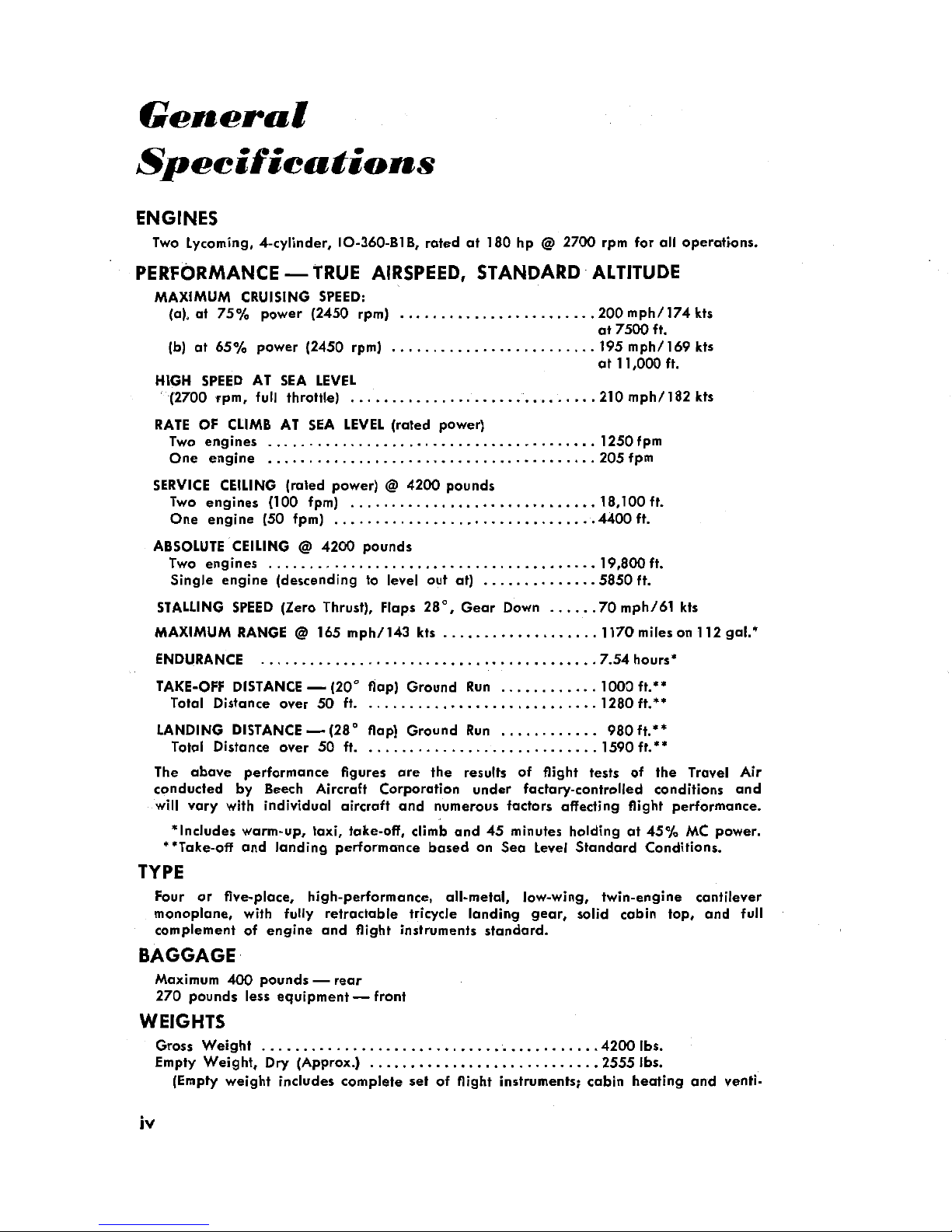
ENGINES
Two Lycoming, 4-cylinder,
10-360-B1B,
rated
at
180 hp
@
2700 rpm for
all operations.
PERF0RMANCE
--
TRUE
AIRSPEED,
STANDARD
ALTITUDE
MAXIMUM
CRUISlNG
SPEED:
(a), at
75% power
(2450 rpm)
........................200mph/174kts
at 7500 ft.
(b)
at
65¾
power (2450 rpm)
.........................195mph/169kts
at 11,000
ft.
HIGH SPEED AT SEA LEVEL
(2700 rpm,
full
throttle) ..............................210mph/182kts
RATE OF CLIMB AT
SEA
LEVEL(rated power)
Two
engines ........................................ 1250fpm
One engine ........................................
205fpm
SERVICE CEILING (rated
power)
@
4200 pounds
Two engines (100
fpm)
..............................18,100ft.
One
engine
(50
fpm)
................................4400ft.
ABSOLUTE CEILING
@
4200 pounds
Two engines ..................
... .................19,800ft.
Single engine
(descending
to level out
at) ..............5850ft.
STALLING SPEED
(Zero
Thrust), Flaps
28°,
Gear Down ......70mph/61kts
MAXIMUM RANGE@165 mph/143
kts
...................1170mileson112
gal.*
ENDURANCE
................. .
...................7.54hours*
TAKE-OFF
DISTANCE-(20°
flap)
Ground Run
............1000ft.**
Total
Distance over 50
ft.
............................1280ft.**
LANDING
DISTANCE-(28°
flap)
Ground
Run ............
980ft.**
Total Distance over
50 ft.
............................1590ft.**
The abave performance figures are
the results of flight
tests
of
the
Travel
Air
conducted by Beech
Aircraft Corporation under
factary-controlled
conditions
and
will vary
with
individual aircraft and
numerous factors
affecting
flight performance.
*Includes
warm-up, taxi,
take-off, climb and 45 minutes
holding at 45%
MC power.
**Take-off
and
landing
performance based on Sea Level Standard Conditions.
TYPE
Four
or five-place,
high-performance,
all-metal,
low-wing,
twin-engine cantilever
monoplane, with
fully
retractable
tricycle
landing
gear,
solid
cabin top, and
full
complement
of eng¡ne
and
flight instruments
standard.
BAGGAGE
Maximum
400
pounds
-
rear
270
pounds less
equipment-front
WEIGHTS
Gross
Weight
.........................................4200lbs.
Empty
Weight,
Dry (Approx.) ............................2555lbs.
(Empty
weight
includes
complete set of flight
instruments;
cabin
heating
and
venti-
iv
Iating system
with windshield
defrosters;
soundproofing; navigation,
cabin,
instrument
and
landing
lights.)
Useful Load
(Approx.) ............... ..................1645Ibs.
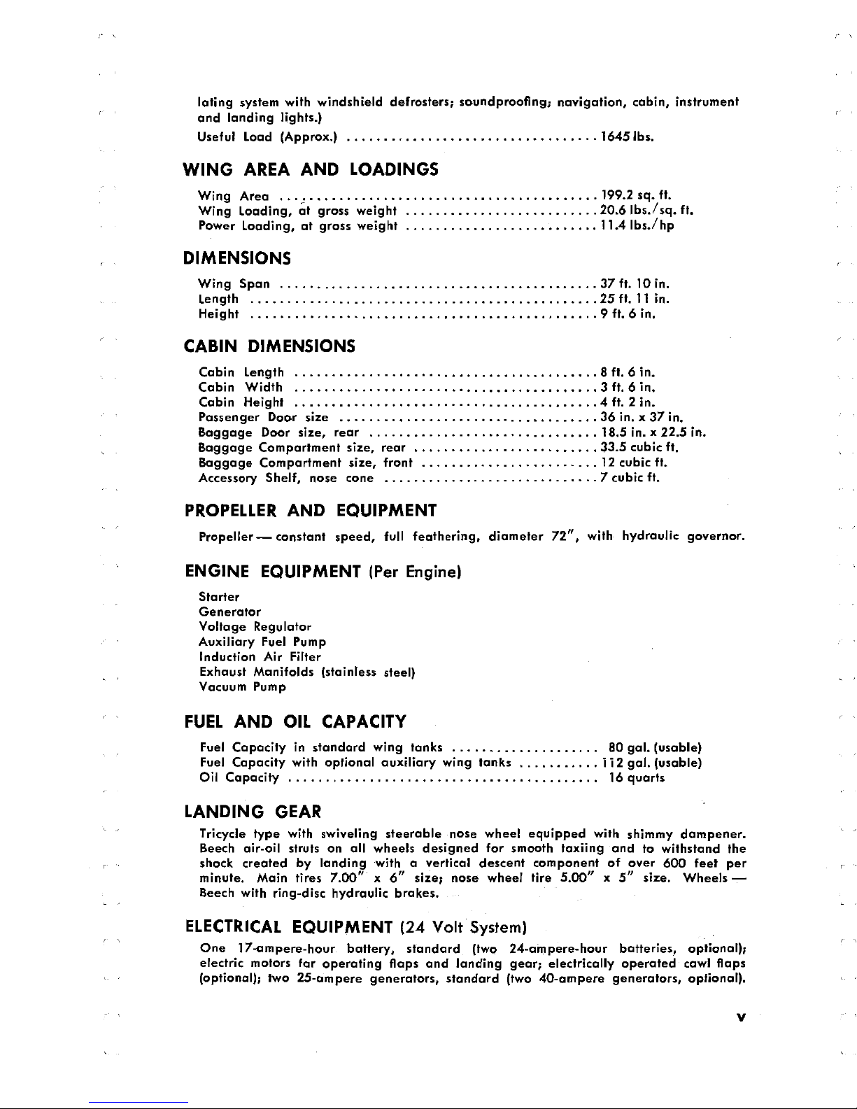
WING AREA
AND LOADINGS
Wing
Area
...... .....199.2sg.ft.
Wing
Loading,
at gross weight ..........................20.6Ibs./sg.ft.
Power
Loading, at
gross weight
..........................11.4Ibs./hp
DIMENSIONS
Wing Span
...........................................37ft.10in.
Length ...............................................25ft.11in.
Height
...............................................9ft.6in.
CABIN DIMENSIONS
Cabin
Length .........................................8ft.din.
Cabin
Width .........................................3ft.6in.
Cabin
Height
.........................................4ft.2in.
Passenger
Door size
...................................36in.x37in.
Baggage
Door size, rear
...............................18.5in.x22.5in.
Baggage
Compartment
size,
rear
.........................33.5cubicft.
Baggage Compartment
size, front
........................12cubicft.
Accessory
Shelf, nose
cone
.............................7cubieft.
PROPELLERAND EQUIPMENT
Propeller-constant
speed, full
feathering,
diameter
72",
with
hydraulic governor.
ENGINE EQUIPMENT
(Per Engine)
Starter
Generator
Yoltage
Regulator
Auxiliary
Fuel
Pump
Induction Air Filter
Exhaust Manifolds (stainless
steel)
Vacuum
Pump
FUEL AND
OIL CAPACITY
Fuel
Capacity
in
standard
wing tanks
....................
80gal.(usable)
Fuel
Capacity with optional
auxiliary
wing tanks ...........112gal.(usable)
Oil Capacity
.................... .....................
16quarts
LANDING
GEAR
Tricycle
type
with
swiveling
steerable nose
wheel eguipped
with
shimmy
dampener.
Beech
air-oil
struts on
all
wheels designed
for smooth
taxiing
and to withstand the
shock created
by
landing
with a vertical
descent component
of over
600
feet per
minute.
Main tires 7.00" x
6"
size; nose wheel
tire 5.00" x
5"
size. Wheels
-
Beech with
ring-disc
hydraulic brakes.
ELECTRICAL
EQUIPMENT
(24
Volt
System)
One
17-ampere-hour
battery,
standard
(two
24-ampere-hour
batteries,
optional);
electric motors far
operating flaps
and landing gear; electrically
operated cawl flaps
(optional); two 25-ampere
generators,
standard
(two
40-ampere
generators,
optional).
V
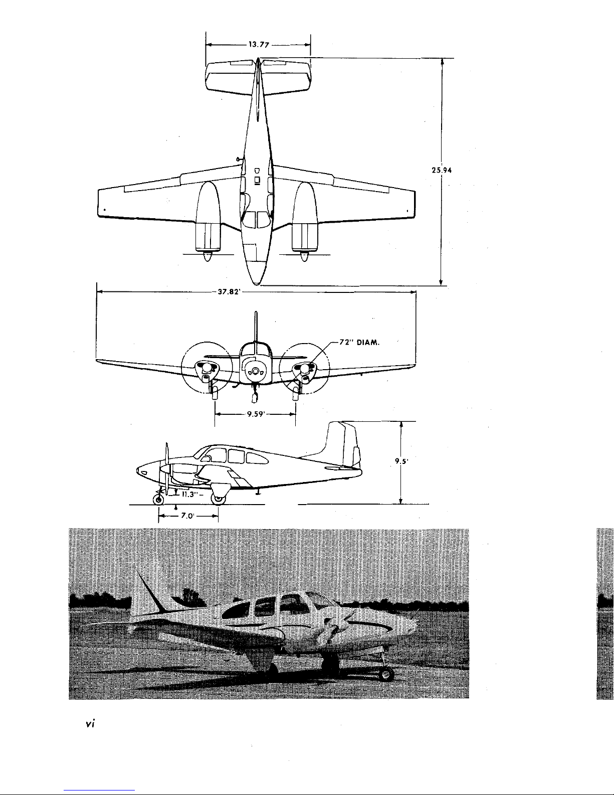
13.77
f
25.94
37 82
72" DIAM.
o.
I
9.59'
!).3"
7.0
VI
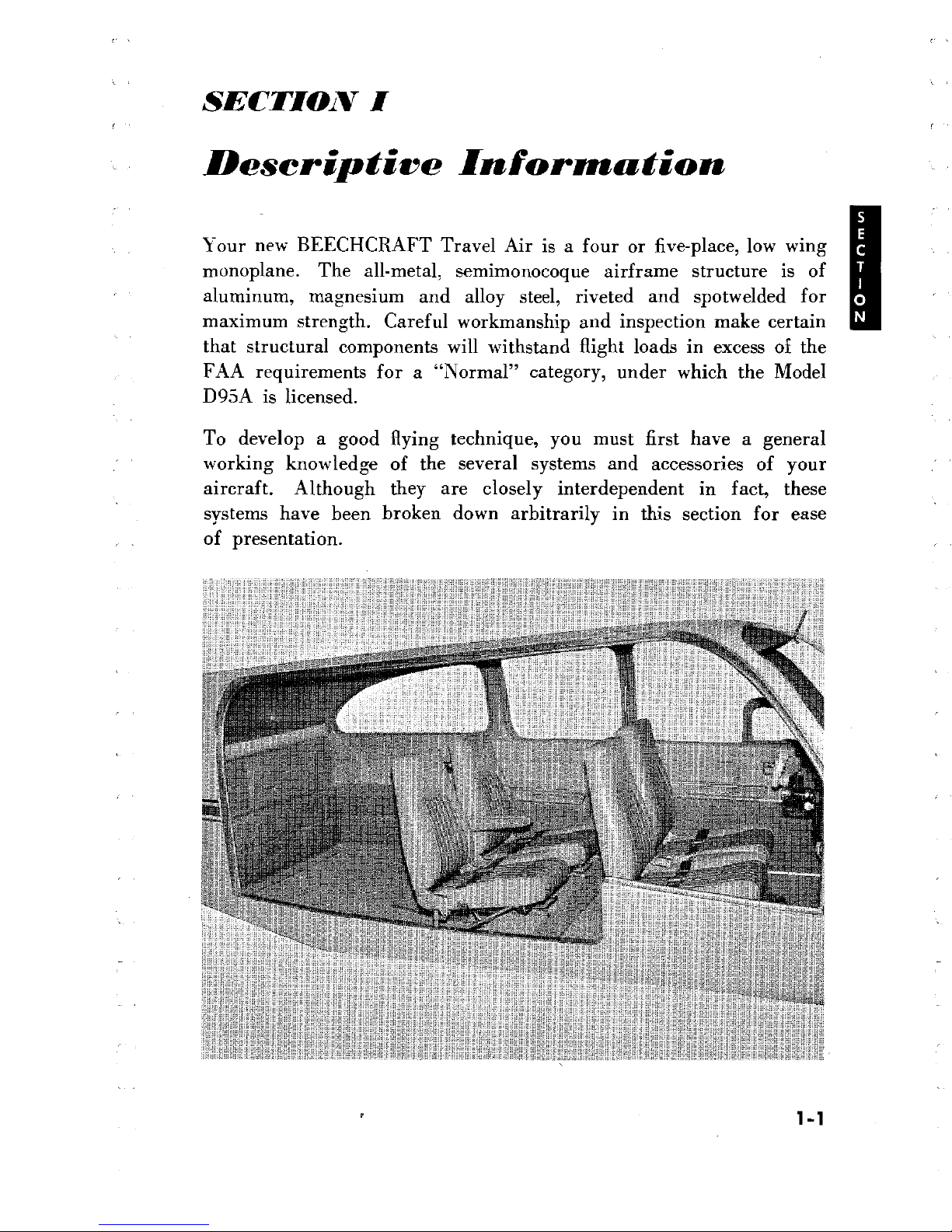
SECTION I
Descriptive
Inforrnation
Your new
BEECHCRAFT
Travel Air
is a
four or
five-place, low wing
monoplane.
The all-metal,
semimonocoque airframe structure is
of
aluminum,
magnesium
and alloy
steel,
riveted and spotwelded for
maximum strength. Careful
workmanship
and inspection make certain
that structural
components
will withstand flight loads in excess of
the
FAA requirements for
a
"Normal" category, under
which the Model
D95A
is licensed.
To develop
a
good
flying
technique,
you must first have a general
working knowledge
of the
several
systems and
accessories
of your
aircraft. Although they are
closely
interdependent in
fact, these
systems have
been
broken
down
arbitrarily
in this section for
ease
of presentation.
1-1
FLIGHT
CONTROLS
Primary
movable
control surfaces of
the Travel
Air
are
operated
through
push-pull
rods and conventional
closed-circuit
cable systems
terminating in
bell
cranks. The
pre.formed,
extra-flexible
steel cables
run
over phenolic pulleys with sealed
ball
bearings
which
ordinarily
require no
lubrication
and insure
smooth,
free
action and long
cable
life. Standard equipment
provides
a
throw-over
type
control
wheel
arm
for elevator and aileron control
which
may be
locked
in
posi-
tion on either the pilot
or
copilot
side and
pilot's
rudder pedals
adjustable fore
and aft to fit individual requirements. The right
hand rudder
pedals
(optional)
may be laid
flat
against
the floorboards
when not in use. Trim
tabs on the
elevator
and rudder control
sur-
faces
are adjustable from the
control
console
through
closed-circuit
cable systems
which
drive
jackscrew
type
actuators.
Position
indicators
for each
of the trim tabs are
located
near the
respective controls.
Aileron trim
is accomplished by
actuating
the aileron trimmer
on
the control column hub. The
trimmer
displaces the aileron surfaces
themselves
to
compensate for
uneven
loading.
The displacement is
maintained
by cable loads imposed
by
the
aileron
trimmer.
Single, slot-type wing
flaps are operated through a system
of
flexible
shafts and jackscrew
actuators driven
by
a reversible electric
motor
located under the front seat. The
flap
position lights on
the
left side
of
the control console
show
green for the
up
position and red
for
the full down
(28°)
landing
position. Intermediate flap
positions
of
10°
and
20°,
as marked on
the leading edge of the left
flap, may
be selected
by moving
the three position control switch on the
left
side of the console to "OFF" when the
desired
flap
setting
mark lines
up with
.
the wing
trailing
edge. Limit
switches automatically
shut
off
the flap motor
when the
full
up
or
down position is reached.
LANDING GEAR
The Travel
Air's extra
strong, electrically
operated
tricycle
landing
gear incorporates
all of the
advantages provided
by
this type gear.
The ease
of
ground
operation is assisted by the
increased
visibility,
more positive directional
control for
parking or
operation
under high
surface
wind conditions, decreased
stopping
distance and longer
brake and
tire
life;
these
are
but a few
of
the
advantages.
1-2
The gear is operated through
push-pull
tubes by a reversible electric
motor and actuator gear box under the front seat. The motor is
controlled
by
a two-position landing gear switch located on the
right hand side of the control console. Limit switches and a dynamic
braking system automatically stop
the retract
mechanism when
the
gear
reaches
its full up
or
full
down position.
With the landing gear in the up position, the wheels are completely
enclosed by
fairing
doors which are operated
mechanically by
the
retraction and extension
of the
gear.
After the gear is lowered, the
main gear inboard
fairing doors automatically close,
producing
extra
lift and reduced
drag
for
take-off
and
landing.
Individual uplocks
actuated by the retraction
system lock
the
main
gear
positively
in the
up position. No downlocks
are
necessary
since
the
over-center
pivot
of the linkage forms a geometric
positive lock
when the gear is
fully
extended. The
linkage
is
also
spring
loaded
to
the
over-center
position.
Landing gear position
lights,
located above the
landing
gear
switch,
indicate the position
of the
gear,
either
up
or
down, coming
on
only
when
the
gear reaches
its
fully
extended or retracted position. In
addition,
a mechanical indicator beneath the control console shows
the
position
of the nose gear at all times.
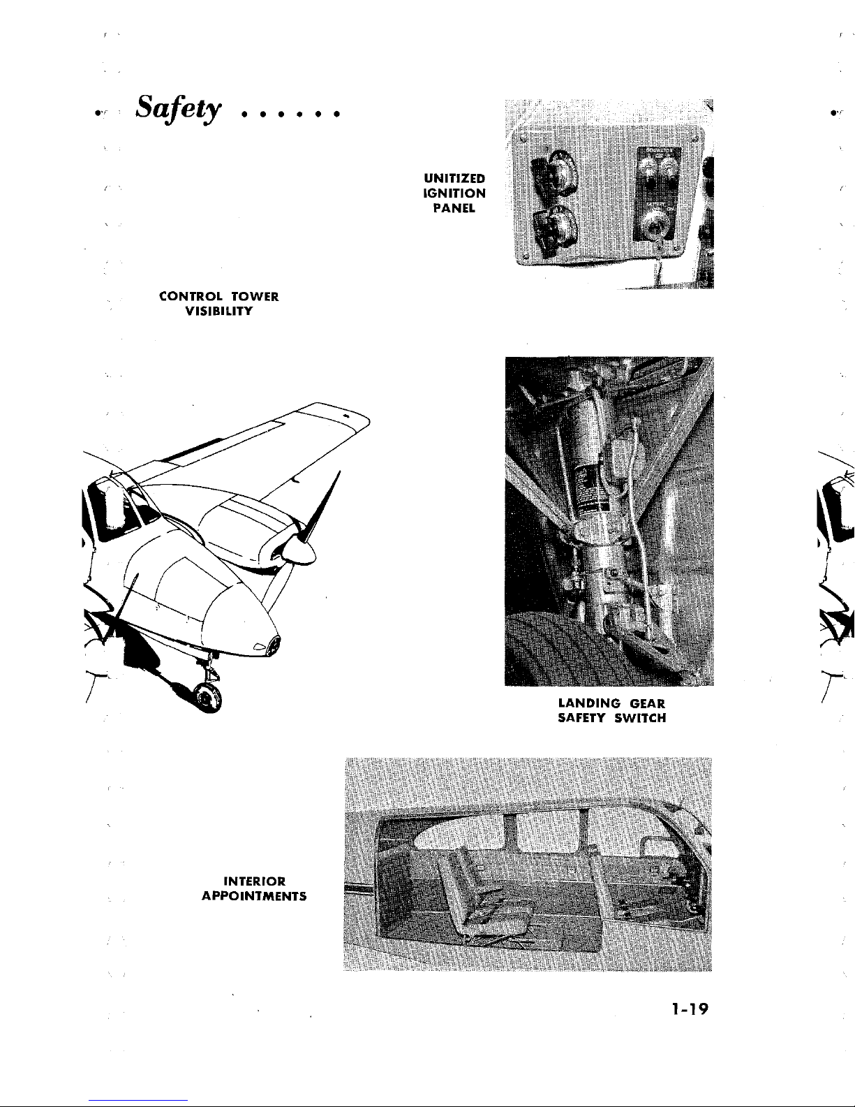
To prevent accidental gear retraction on
the
ground, a
safety
switch
on the left main strut breaks the
control
circuit whenever
the
strut
is
compressed by the
weight
of the airplane and completes the circuit
so the gear may be
retracted, when the strut
extends.
Never rely on
the
safety
switch
to
keep
the
gear down while
taxiing or on
take-off
or
landing
roll. Always check the position of the
switch
handle.
With the gear
retracted, if
either or both
throttles
are retarded below
an engine
setting
sufficient
to
sustain flight, a
warning
horn
will
sound
an intermittent note.
During
single-engine
operation the horn
may
be silenced by
advancing
the throttle of the
inoperative
engine enough
to open
the landing
gear
warning
horn switch.
The nose wheel
assembly
is made steerable
through
spring loaded
linkage, connected to the rudder pedals
for
greater maneuverability
during
taxi
operation. The
retraction
of the
gear
relieves the
rudder
pedals of their nose
steering
load and centers the
wheel,
by a roller
1-3

and slot arrangement, to insure
proper retraction into
the
wheel
well.
A hydraulic dampener
on the
nose
wheel
strut compensates
for the
inherent
shimmy
tendency
of
a
pivoted
nose
wheel.
Wheels are
carried
by
heat treated tubular
steel trusses
and use
Beech
air-oil
type
shock
struts.
Since
the shock
struts are
filled
with
both
compressed air
and hydraulic
fluid,
their
correct inflation
should
be
checked prior
to each flight.
Even
brief
taxiing
with
a
deflated
strut
can
cause
severe
damage.
For manual operation of the
landing
gear
(lowering only)
a
handerank
is
located
behind the front seats. The
crank,
when engaged, drives
the
normal
gear
actuation
system.
Main
landing gear wheels are
equipped with
BEECHCRAFT
ring-disc,
self-adjusting,
self-energizing
hydraulic
brakes actuated
by
individual
master
cylinders connected to the
rudder pedals
and operated as
toe
brakes.
The
hydraulic brake fluid reservoir is
accessible
from
the
forward
baggage compartment and should
be
checked
occasionally
for specified fluid
level. The
parking
brake
is
set by
a
push-pull
control
with
a
center-button
lock
and is
located just
to
the left
and slightly
below the control
console.
Setting
the
control
does not pressurize the
brake system, but
simply
closes
a
valve in the lines
so
that pressure
built up by pumping
the
toe pedals is retained and the brakes remain
set. Pushing the
control
in
opens
the
valve
and
releases
the
brakes.
POWER PLANTS
Your
Travel Air is powered
by two
Lycoming
IO-360-BlB
engines
rated
at 180 horsepower each, at 2700
rpm,
for
take-off
and
maximum
continuous operation. The four-cylinder, opposed, aircooled
engines
have direct propeller drives and a
compression ratio of
8.5:1.
Pres-
sure type
cowlings
are
used;
cooling
is controlled
by a
gill-type
flap
on
the
lower
trailing edge
of each
cowling. Fuel
distribution
is
accom-
plished
with a
constant-flow
fuel injection
system which
incorporates
a special aerated nozzle at
the
intake port
of
each
cylinder. Filtered
induction system
air is obtained through
a filtered airscoop on
the
lower
front of the engine
and directed
to
the air throttle valve.
A
spring loaded
door
on the
bottom
of
the air box opens
automatically
if
the
airscoop is
blocked
by
impact
ice
or dirt. Manual
controls
on
the control
console
may
be
used
to select
either filtered
or
alternate
air. Full dual ignition systems are
used,
with
an
ignition
vibrator
1-4
supplying
starting
voltage. The
electrical system uses
Delco-Remy
starters,
generators, and
voltage regulators. Fuel
injection pumps,
vacuum
pumps, and
constant-speed propellers are standard
equip-
ment. Other
features include
sodium-cooled
rotator-type
valves,
chrome
piston
rings and a nitrided
crankshaft.
Constant-speed, two-bladed, hydraulic, full feathering
propellers use
pressure from a
feathering
spring
and centrifugal force from the blade
shank counterweights to increase pitch. Engine oil under
governor-
boosted pressure
decreases pitch.
Propeller
feathering is
accomplished by pulling the propeller
control
back past
the detent to the
limit
of travel.
Unfeathering and restarting
is
achieved by moving the
propeller
control well into the governing
range and
following
the normal
starting
procedure. On airplanes
with
the optional unfeathering
accumulator,
momentary use
of the
starter to initiate rotation
is necessary only at low airspeeds.
Imme-
diately
after the
engine starts, the
throttle
and
propeller controls should
be adjusted to
prevent
an engine over-speed condition.
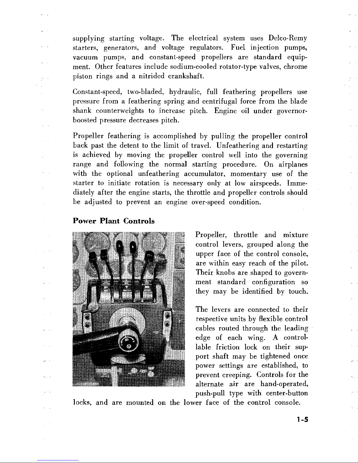
Power
Plant Controls
Propeller, throttle and mixture
control
levers, grouped along the
upper
face
of the
control console,
are within
easy
reach
of
the pilot.
Their knobs
are shaped
to
govern-
ment standard configuration so
they may
be identified by
touch.
The levers
are connected to
their
respective units
by
flexible
control
cables routed
through the
leading
edge of each
wing. A
control-
lable friction
lock on
their
sup-
port shaft may be
tightened once
power
settings are
established,
to
prevent creeping. Controls
for
the
alternate air are hand-operated,
push-pull
type
with
center-button
locks, and are
mounted on the
lower face
of the control
console.
1-5
Direct-cranking electric starters are
relay-controlled
and are energized
by
spring
loaded,
combination
magneto-starter
switches,
located on
the
ignition
panel. These spring
loaded
switches return
to
the
"BOTH"
position
when released.
The
push-pull,
buttondock
type
controls that
operate
the engine cowl flaps are located aft
of
each fuel selector valve
handle. The optional
electrically
operated
cowl flaps are controlled
by
switches on the electrical panel located to the left of the
control
console.
An indicator light adjacent to
the
switches comes on whenever
the electric
cowl
flaps are not fully
closed.
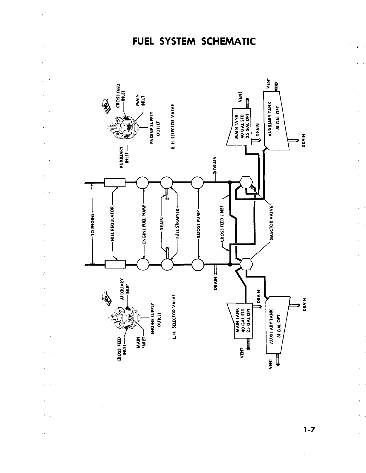
Fuel System
The
Travel
Air's
fuel system consists
of
a
separate,
identical supply
for
each
engine,
interconnected
by
crossfeed
lines for emergency
use.
During normal operation
each engine
uses
its own fuel
pumps
to
draw
fuel from its respective
fuel cell arrangement.
However,
on
crossfeed
operations the entire fuel
supply
of
any or all
cells
may
be consumed
by
either engine.
A
fuel
selector
valve for
each engine
controls the
cells
from which fuel is used.
The standard fuel cell arrangement consists of
one
40-gallon fuel
cell
in
the
inboard portion of each wing
leading
edge. Total fuel capacity
for this system
is 80
gallons
of usable fuel. With an optional fuel
cell
arrangement
of
one
25-gallon main
fuel cell
in
each
wing leading
edge
and one
31-gallon
auxiliary
cell
just aft
and outboard
of
each
main cell, the total capacity is raised to 112 gallons of usable fuel.
Fuel cannot transfer from one cell
to
another
during
flight.
Fuel
quantity
is measured
by a
float-type transmitter unit
in each
cell,
which transmits a signal
to
the fuel gages on the
instrument panel.
When the optional ll2-gallon installation
is used, a
two-position
switch determines
the
cell,
main or auxiliary, to which
the gage is
connected. Each
cell
is filled through its own filler neck with
open-
ings in
the
upper
wing
surface
and
sealed
with
flush-type
filler
caps.
An
electric
auxiliary
fuel
pump
for
each engine supplies
fuel pressure
for starting and provides for near
maximum
engine
performance
should
the
engine-driven
pump fail. The
auxiliary fuel
pumps
are
used for
starting
and
emergencies,
and
may
be used for
take-off
and landing.
In extremely hot weather they should be employed for all
ground
oper-
ations,
take-off,
climb,
and landing.
Due to
the
in-line
location of the
1-6
TO
ENGINE
CRON
ETFEED
AUXILIARY
FUEL REGULATOR
AUXILIARY
CR
LSEFEED
INLET
INLET
MAIN
MAIN
INLET
ENGINE
FUEL
PUMP INLET
ENGINE
SUPPLY
ENGINE SUPPLY
OUTLET
DRAIN
OUTLET
L.H. SELECTORVALVE
R.
H
SELECTOR VALVE
FUEL STRAINER
BOOST PUMP
DRAIN
DRAIN
VEN
CROSS
FEED
LINES
ENT
DRAIN
DRAIN
VENT
AUXILIARY TANK
SELECTOR VALVE
AUXILIARY
TANK
VENT
31GALOPT
31GALOPT
DRAIN
DRAIN
I
auxiliary
fuel
pumps, between
the cells
and
metering
unit, fuel
may
be drawn
from
any
cell within
the
system
by the
auxiliary
pump for
the operating engine. The
fuel
system is drained at
eight
different
locations
(including
the two
optional
auxiliary
cell
sumps) as shown
in the
fuel system schematic
and
the
servicing
diagram.
Fuel
system
strainers
are located on the
wing
main
spar in each wheel
well
and
at the
inlet
to
the
fuel
control units. Regular
checking
of the strainers
is of
utmost
importance
to
preventive
maintenance, since
lowered fuel
pressure
may
often
be
traced
to
contaminants
clogging the system.
A
fuel flow indicator
on
the instrument
panel is calibrated in gallons
per hour, based on system pressure at
the fuel manifold valve
of
the fuel
injection unit. The instrument
also indicates fuel pressure
for
starting.
Oil
System
The
engine oil system is of the full-pressure,
wet-sump
type and has
an 8-quart
capacity.
For safe engine operation, the absolute
minimum
amount of
oil required
in the
sump
is
2
quarts.
Oil
operating
temperatures are controlled
by
an
automatic thermostat
by-pass
control
incorporated
in the
engine oil
passage of each system. The
automatic
by-pass
control will prevent oil flow
through
the cooler when operating
temperatures are below normal. It also
will
by-pass
if
the radiator is
blocked.
System
servicing
and
draining
points are shown on
the
servicing
diagram. The
determining
factor for
choosing
the correct
grade
of
oil
is
the
oil
inlet temperature which is observed
during
flight; inlet
temperatures
consistently
near
the
maximum
allowable
would
indicate
a heavier oil is needed.
Straight
petroleum
base,
aviation
grade,
nondetergent oil of the lightest weight that will provide
adequate
cooling
should
be
used. Certain additive
type
aviation grade oils are also
approved
by the
engine
manufacturer,
but
they
should be
used
with
caution. (See
servicing
information and Consumable Materials Chart
in
Section
VII.)
Condensed moisture in the oil
sump
may
be
drained
by
occasionally
opening
the
oil drain valve and
allowing
a small amount of
oil to escape;
ideally,
this
draining
should
be
done
when the
engines
have been
stopped overnight or approximately 12 hours. This procedure
should
be followed more
closely during
cold weather
or
when
a
series of short
flights of
less
than 30
minutes
duration have
been
made and
the
engines allowed
to cool completely between such flights.
INSTRUMENTS
All
flight and engine instruments
are
positioned
on
the
instrument panel
1-8
for maximum
utility
and convenience. Instrument
markings are
matte
white on a black background and where practicable,
the normal
oper-
ating
limits are indicated.
The
flight
instruments
are located on a hinged floating panel
directly
in
front of the
pilot's seat.
Standard flight instrumentation
includes
atti-
tude and directional
gyros, airspeed,
altimeter,
rate-of-climb, electric
turn-and-bank,
and a clock. The airspeed indicator is marked with
a
special
blue
line
range
for
single-engine
operation. An
outside air
temperature thermometer
and
magnetic compass are
mounted on the
windshield divider.
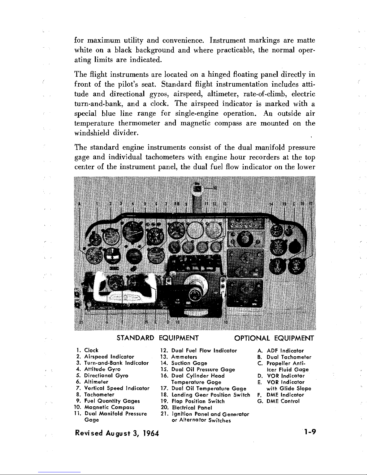
The standard engine
instruments
consist of the
dual manifold
pressure
gage
and
individual
tachometers with engine hour recorders at the top
center of the
instrument
panel,
the
dual fuel
flow
indicator on the lower
STANDARD
EQUIPMENT OPTIONAL EQUIPMENT
1.
Clock
12.
Dual Fuel Flow Indicator A. ADF
Indicator
2. Airspeed
Indicator
13.
Ammeters
B. Dual
Tachometer
3.
Turn-and-Bank
Indicator
14.
5uction Gage
C.
Propeller
Anti-
4.
Attitude Gyro 15.
Dual
Oil Pressure
Gage
Icer
Fluid
Gage
5.
Directional
Gyro 16.
Dual Cylinder Head
D.
VOR
Indicator
6.
Altimeter
Temperature
Goge E.
YOR
Indicator
7.
Vertical
5peed
Indicator 17.
Dual
Oil Temperature
Gage with Glide
Slope
8.
Tachometer
18. Landing Gear
Position Switch
F. DME
Indicator
9.
Fuel
Quantity
Gages 19.
Flap Position
Switch
G.
DME
Control
10.
Magnetic
Compass 20.
Electrical
Panel
11.
Dual
Manifold
Pressure 21.
Ignition
Panel
and
Generator
Gage
or
Alternator
Switches
Revised
August
3,
1964
1-9
left
hand side
of
the
panel, and the dual oil temperature,
oil
pressure,
and
cylinder head temperature
gages plus a
suction
gage on the right
hand side of
the panel. When the optional dual tachometer is
installed,
the fuel flow indicator
is mounted adjacent to the manifold
pressure
gage
in the
top
center portion
of
the
panel. Fuel
quantity
is
shown
by
two separate
gages,
each
gage serving
both
the
standard
and
the
optional
fuel
tank
in
each wing. The gages are mounted
with
the ammeters
just
above the control console.
Impact air pressure and
atmospheric
air
pressure for
the
airspeed
indicator,
altimeter,
and vertical speed indicator
are supplied
by
the
pitot
and
static air systems.
Since the
accuracy of
these instruments
depends on accurate
pickup of
the
two
pressures,
the
systems have
been developed
carefully
and
tested
in
flight with highly
accurate
special
equipment.
To
insure
the
proper operation
of these
instru-
ments, drain the systems regularly and keep the static
ports clear
of obstructions.
ELECTILICAL
SYSTEM
The Travel Air's
direct-current
electrical
power system uses
either,
one
17-ampere-hour
24-volt
battery,
or
two
25-ampere-hour
12-volt
batteries,
in
any standard or
optional
combination with two 25-ampere
12-volt
generators,
or
two 50-ampere
alternator rectifiers. Either
battery
in-
stallation is
mounted in
the
lower
portion
of the
nose
section;
both
generator
installations
are
belt driven
from
the
engine crankshaft.
In
general, the
aircraft's
circuitry
is the
single-wire,
ground-return
type
with the aircraft
structure itself
being
used as the ground return.
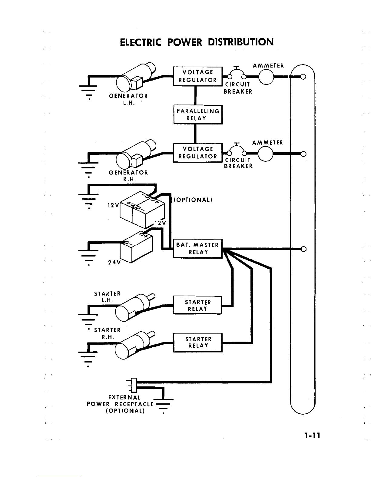
On
the
standard
generator
installation,
each generator's
electrical out-put
is
automatically controlled
by
its
respective
voltage regulator and the
system's common generator paralleling relay.
This
paralleling
relay
equalizes the
out-put or
load for each
generator.
The system electrical
reading
is
then
indicated on the direct reading
type
(not the
charge-
discharge type)
ammeters located on the
instrument
panel just
above
the
control
console.
These
ammeters indicate
individual
generator out-put
and
also serve
as system load-meters,
i.e.,
an ammeter
indication will
increase or
decrease in direct proportion
to the electrical
load
applied.
On
the
optional, or alternator
installation,
both alternators are
con-
trolled
by
two fully transistorized electronic voltage
regulators,
however,
1-10
Revised
August 3,
1964
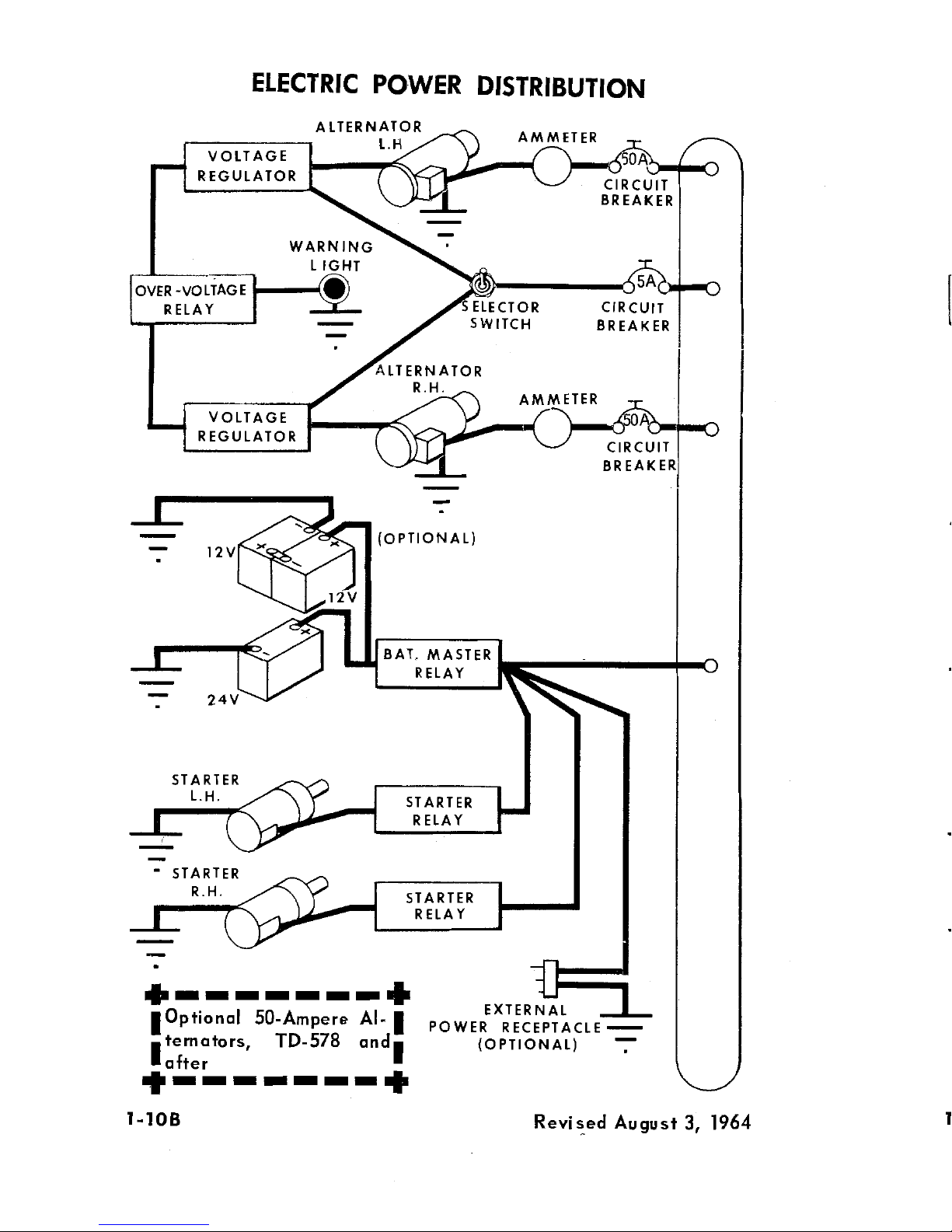
only
one. regulator is operable
in the
system at
a
time; the
remaining
regulator
being
used as an
alternate
or standby.
Either
of
these
regu-
lators when switched into the circuit will
automatically
adjust
alternator
out-put to the required electrical load, including battery
recharging.
These electronic voltage regulators provide usable current out-put
at low
engine
rpm. Each alternator will produce approximately
20
amperes
at 1100
engine rpm. Selection of a regulator
is
made by
a
select switch placarded I and
2, located
on the ignition switch
panel.
System
protection
against overvoltage is
provided
by
an
overvoltage
relay
which disconnects the alternators
from
the aircraft bus
should
an overvoltage
condition
occur.
A
press-to-test
overvoltage warning
light located on the instrument panel illuminates
whenever the
alter-
nator
is
disconnected from the
aircraft bus
by
the overvoltage relay.
Should
an overvoltage condition occur (illumination of overvoltage
warning
light), switch
to
the
standby
voltage regulator,
either
1 or
2
as
necessary. Should the
condition
persist,
pull
the
alternator
field
circuit
breaker
(5-ampere)
and correct the discrepancy prior to the next flight.
Illumination of this light provides a
warning
that electrical
current
consumption should
be
minimized
since only
battery
power
is available
with
the
alternators
shut-off.
The circuit is also designed so that the
alternators are
automatically shutoff
whenever
the battery
master
switch
is OFF.
CAUTION
To protect the alternators
from
overheating, do not
use
more
than 45 amperes from
either alternator
while operating on the
ground
at temperatures
above
100°
F
(38°
C) or
in flight at
altitudes
above
14,000 feet with outside air temperature above
45°
F
(70°
C).
A
panel containing the magneto,
starter, battery,
and generator
switches
is
located below the pilot's storm window. On aircraft
equipped
with
alternator
generators, this
panel is modified by
replacing
the generator
switches with alternator control
switches
and the addition of a regulator
1 and
2 switch and
a
5-ampere alternator field circuit
breaker.
Placards
indicate the particular circuit
controlled
by
the electrical
switches
and
individual circuit breakers in the panel to the
left
of the control console.
Refer to Section VII for
alternator
servicing and maintenance
in-
formation.
Revised
August
3, 1964
1-10A
ELECTRIC
POWER
DISTRIBUTION
RG
ATOER
WARNING
LIGHT
OVER
-VOLTAGE
RELAY
SELECTOR CIRCUIT
..--
SWITCH
BREAKER
ALTERNATOR
REGUL
GER
(OPTIONAL)
12V
12V
>c
BAT,
MASTER
RELAY
24V
STARTER
L.H
STARTER
RELAY
STALRATER
-------
EXTER
Optional
50-Ampere
Al-
POWER
RECEPTACLE
--
ternators,
TD-578
and
(OPTIONAL)
¯
1-10B
ROYised
August
3,
1964
ELECTRIC
POWER
DISTRIBUTION
VOLTAGE
AMMETER
REGULATOR
CIRCUIT
BREAKER
-
GENERATOR
L.H.
PARALLELING
RELAY
AMMETER
VOLTAGE
REGULATOR
CIRCUIT
BREAKER
-
GENERATOR
R.H.
(OPTIONAL)
12V
12V
BAT.
MASTER
RELAY
24V
SRTARTER
STRARATER
EXTERNAL
POWER
RECEPTACLE
-
(OPTIONAL)
T
1-11
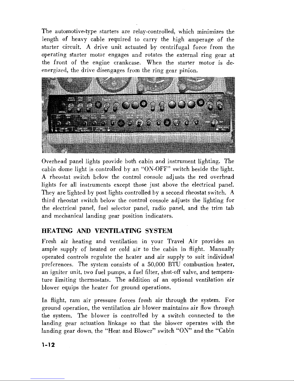
The automotive-type
starters
are
relay-controlled,
which
minimizes
the
length
of heavy
cable
required to carry the high
amperage
of
the
starter circuit. A drive unit actuated
by
centrifugal force from the
operating starter motor engages
and
rotates
the
external
ring
gear
at
the front
of
the
engine erankease. When the starter
motor
is
de-
energized, the
drive
disengages from
the
ring
gear
pinion.
Overhead panel lights provide both cabin and instrument lighting.
The
cabin dome light is controlled by an
"ON-OFF"
switch beside the
light.
A rheostat
switch
below
the
control
console adjusts the
red
overhead
lights for
all instruments
except
those
just
above
the
electrical
panel.
They
are
lighted by post lights
controlled by a
second
rheostat switch. A
third rheostat switch below the control console adjusts the
lighting
for
the electrical
panel,
fuel
selector panel,
radio
panel,
and the trim tab
and mechanical
landing gear
position indicators.
HEATING AND VENTILATING SYSTEM
Fresh air
heating
and ventilation
in
your
Travel
Air provides an
ample supply of heated or cold
air
to the cabin in flight. Manually
operated
controls
regulate
the
heater
and air supply to
suit
individual
preferences.
The system consists of a 50,000 BTU combustion heater,
an
igniter
unit, two fuel pumps, a fuel filter,
shut-off
valve,
and
tempera-
ture
limiting
thermostats.
The
addition of an optional
ventilation air
blower equips the heater for ground operations.
In
flight, ram air
pressure
forces
fresh air through the
system. For
ground operation,
the
ventilation air
blower maintains air
flow through
the system. The blower is controlled
by
a
switch
connected
to
the
landing gear
actuation
linkage so that
the blower operates with the
landing gear down, the "Heat and
Blower"
switch
"ON"
and the
"Cabin
1-12
Air"
control in.
The
blower is
shut
off automatically
when the gear
is retracted, and may
be shut
off
manually with the "Heat and
Blower"
switch or by
pulling the "Cabin
Air" control
out approximately half
way,
which partially closes the iris valve and opens
a
blower
switch
connected
to the control linkage. This switch
also
turns
off
the
heater,
since with the iris valve only
slightly
open, the
intake
air is
insufficient
for proper heater operation.
Heater operation is controlled byaductstat mounted in the right
air
outlet behind
the instrument
panel. It acts as a cycling
thermostat
to
maintain the temperature selected with the "Cabin Heat" control
be-
neath the electrical panel. The ductstat's
upper
limit is
set
at
180°
F
to
prevent
uncomfortably-hot
air from
entering
the cabin. To obtain more
cabin heat
during
flight
in
low
outside
air temperatures, pull the "Cabin
Air"
control out
as
far
as possible without
shutting off
the heater. This
reduces the volume
of incoming cold
air
and allows the heater to raise
the temperature of the air to
a
comfortable level.
A
normally-open
thermostat in the heater discharge
plenum
acts as
a safety device
to render the heater system,
except
the
blower,
inoperative
if a
malfunction
should occur
which
results in
dangerously-
high temperatures. This thermostat is set to close at
300°F,
grounding
a
fuse in the heater power
circuit.
The fuse
is
located on the upper
right
hand segment of the bulkhead behind
the
instrument panel. This
location
was chosen
deliberately for inaccessibility in
flight, to
make
certain any malfunction
causing
the overheat
fuse
to blow is corrected
before the heater is operated again.
In flight, fuel for the heater
is
drawn from
the left
main
wing tank by
two electric
fuel pumps.
When the aircraft
is equipped
with the
ventilation air
blower, only
one pump operates
during
ground operation.
This is accomplished
by a
switch
operated
by
the
landing
gear linkage.
The heater fuel line is
equipped with
a
strainer. A
spring-loaded,
electrically-operated,
solenoid valve closes when the heater is off,
pre-
venting seepage
of
fuel into the heater.
The heater
ignition unit, mounted in the nose
cone, uses
a vibrator to
provide
interrupted current for its
high-voltage
coil.
The
unit is equipped
with two
sets of points; at each
1000-hour
inspection of the
airplane,
the heater electrical system is
modified
to place an unused
set
of contact
points in service.
1-13
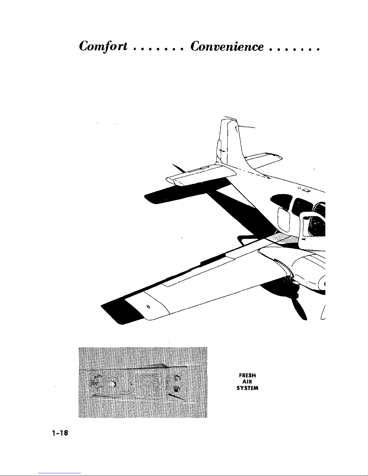
In
addition
to
the air supplied to
the
cabin
through the heater
fresh-air
system,
a manually retractable air
scoop
on
top
of the cabin conducts
outside air
to individual
fresh-air
outlets
in
the
overhead
upholstery
panel
above each seat.
The outlets,
which can be
manually
adjusted
to control both the
quantity
and
direction of air
flow,
allow individual
selection of cool fresh air for each
passenger's
comfort.
During
flight
through inclement
weather or for
maximum
noise suppression, the
air
scoop
may
be
closed by
operating
a
push-pull
control
located
on
the
overhead panel.
It
is
easily
accessible
from
the pilot's
seat.
To further the circulation of
air through
the
cabin,
a manually
con-
trolled
exhaust
vent
is
installed
in
the
overhead
upholstery
panel
behind
the rear seats.
VACUUM SYSTEM
Suction
for the vacuum-operated
gyroscopic
flight
instruments is
supplied
by
two
engine-driven
vacuum
pumps, interconnected to
form
a single system.
Either vacuum
pump
has sufficient capacity to
maintain
the complete aircraft
gyro
instrumentation.
The suction produced
by
each
pump
is
controlled
by
an
adjustable,
spring-loaded
regulator valve
in the instrument line just ahead of
the
instrument
panel. The valves are set
to
bleed air into the
system as
required
to
maintain the correct suction
supply.
A suction
gage
on
the
instrument panel indicates the
amount
of
suction
in
the
vacuum system in inches
of mercury. A reading
within
the
yellow arc
on the gage
with
both engines
operating
at
cruise power
indicates that the regulator system
requires
adjustment or
that one
vacuum
pump
has failed. The cause
of
an
unsatisfactory
suction
reading should be
determined as
soon as practicable. Failure
of
one
vacuum pump can be
detected
by
noting suction pressure
with
each
engine operating
individually.
Air entering
the system
is
taken
in
through
the
using
instruinents. To
eliminate
dust and grit which
might
damage the
instruments,
each
in-
strument
air intake
is
fitted
with
a filter.
Sluggish or erratic operation
of
vacuum-driven
instruments accompanied by
a
normal suction gage
1-14
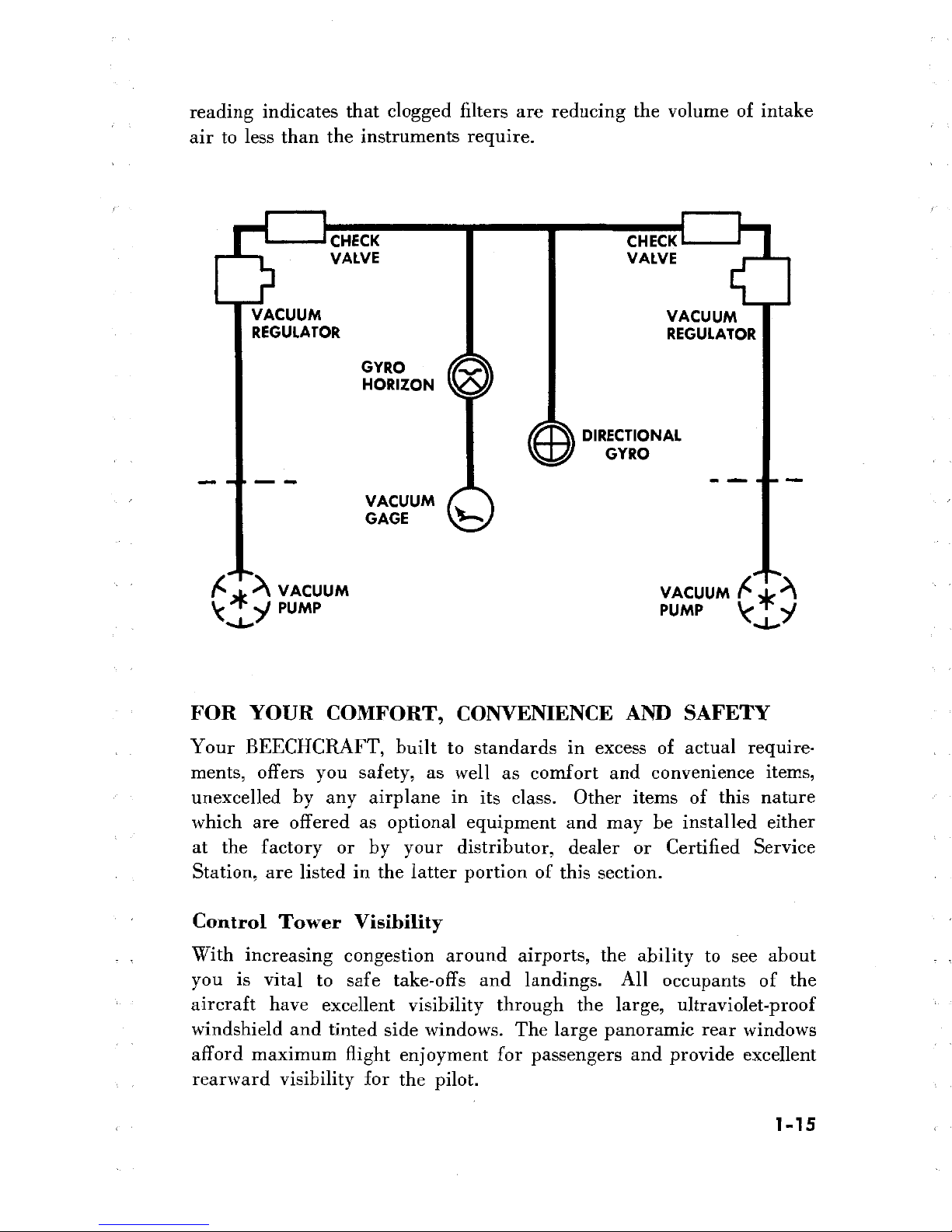
reading
indicates that clogged filters
are
reducing
the volume of intake
air to
less than
the
instruments require.
CHECK
CHECK
VALVE
VALVE
VACUUM VACUUM
REGULATOR REGULATOR
GYRO
HORIZON
DIRECTIONAL
GYRO
VACUUM
GAGE
A
VACUUM
VACUUM
PUMP
PUMP
FOR YOUR
COMFORT,
CONVENIENCE
AND SAFETY
Your
BEECHCRAFT,
built to
standards
in excess
of
actual
require-
ments, offers
you
safety,
as
well
as comfort and
convenience
items,
unexcelled by
any airplane in its class. Other items of this
nature
which
are offered as
optional
equipment and may be installed
either
at
the factory
or by
your
distributor,
dealer
or
Certified
Service
Station, are listed in the latter portion
of
this section.
Control Tower
Visibility
With
increasing congestion around airports, the
ability to see
about
you is
vital to safe
take-offs
and
landings.
All
occupants
of
the
aircraft have excellent
visibility through the
large,
ultraviolet-proof
windshield
and
tinted side
windows. The
large
panoramic rear
windows
afford
maximum
flight
enjoyment
for passengers and provide excellent
rearward
visibility for the pilot.
1-15
Landing
Gear
and
Flap Indicators
The position
of
the
landing gear and the
wing flaps is
indicated
by
signal lights on
the instrument panel.
Also, the flaps are visible
through
the windows
and an
illuminated
mechanical
pointer below the
instru-
ment panel indicates
the position
of
the nose gear.
To avoid
accidental
tripping
of
the landing gear and
flap switches,
each
is
designed
to
be
pulled out of a detent before
it
can
be
repositioned.
Landing Lights
A
sealed-beam
landing light mounted in
the nose
cone
and
an
optional
light
installed on
the
nose
landing
gear
are
scientifically mounted to
produce maximum effectiveness
for
night
landings.
The lights are
operated
independently by
separate
switches
on the electrical
panel;
prolonged operation
during
ground
maneuvering
should be
avoided.
Conventional position lights
on the wing tips and tail
cone
are
operated
through
a
flasher unit
designed
to
give
steady
lights
if
a
malfunction
occurs,
and are controlled
by a
toggle switch
on
the electrical
panel.
The flasher unit is
omitted
when the airplane is
equipped
with either
the
single
or
dual
optional
rotating
beacon installation.
Stall
Warning Indicator
As an impending stall is approached,
a
stall
warning
indicator sounds
a warning horn on
the
left
side
of
the cabin
forward bulkhead while
there is still ample time for the pilot
to
correct his attitude. The
stall
warning indicator, triggered
by
a sensing
vane on the
leading
edge
of the left
wing,
is
equally effective
in
all
flight attitudes and
at
all
weights
and airspeeds. Irregular
and intermittent
at first,
the
warning
signal
will
become
steady as
the aircraft
approaches
a
complete stall.
Safety
Belts
The Beech designed
high-strength
safety
belts on
your Travel Air,
if
properly
worn,
will
keep
occupants
snugly
in
their
seats
in
rough
air
or under rapid deceleration. The
safety
belts
are
mechanically
simple and
comfortable,
and
wearing them, you
have
sufficient
freedom
of movement to
easily
operate
all
the
controls. The nylon
strap
ma-
terial, in
colors complementing the upholstery,
is
soil
resistant and
easily
cleaned. The airline-type
harness buckles may be
fastened
or
released
quickly
and are
easily
adjusted.
1-16
Instrument Panel Glare
Shield
The attractive instrument panel glare
shield,
made
of
foam rubber
encased
in
dull-finish
vinyl, is
shaped
to
cover the contour above and
between the instrument panel and the windshield. This shield,
ex-
tending
aft
over the instrument panel in an eyebrow
effect,
gives
added
protection for the instruments
and
windshield against reflected light
in both
day
and night flying.
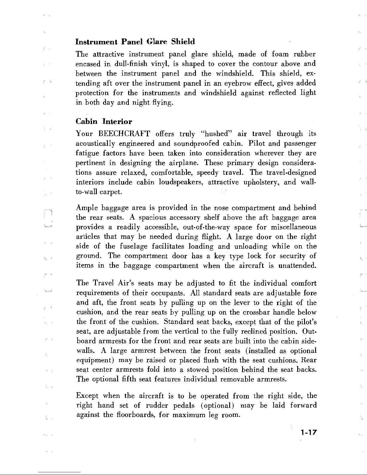
Cabin Interior
Your
BEECHCRAFT
offers truly
"hushed"
air
travel
through
its
acoustically
engineered and
soundproofed cabin. Pilot and
passenger
fatigue factors have
been
taken
into
consideration wherever
they
are
pertinent
in designing the
airplane.
These
primary
design
considera-
tions
assure relaxed,
comfortable, speedy
travel.
The travel-designed
interiors include cabin
loudspeakers,
attractive upholstery, and
wall-
to-wall
carpet.
Ample
baggage area is
provided
in the nose compartment and
behind
the
rear
seats. A spacious
accessory shelf
above the aft baggage
area
provides
a readily accessible,
out-of-the-way space
for
miscellaneous
articles that
may
be needed
during
flight. A
large door
on
the right
side
of the fuselage facilitates loading and unloading
while on the
ground.
The
compartment
door
has a
key type lock
for
security
of
items
in the
baggage
compartment
when the
aircraft
is
unattended.
The Travel Air's
seats may be
adjusted to
fit the individual
comfort
requirements of their
occupants.
All standard seats are adjustable fore
and aft,
the front
seats by
pulling up
on the lever
to
the right of the
cushion, and the rear
seats
by
pulling
up on the crossbar
handle below
the front of the cushion. Standard seat
backs,
except that of the pilot's
seat, are adjustable
from the
vertical
to the fully reclined position.
Out-
board armrests
for
the front
and
rear seats are
built into
the cabin
side-
walls.
A
large armrest between the front
seats (installed
as optional
equipment) may
be raised
or
placed
flush with the
seat
cushions. Rear
seat center armrests fold into
a
stowed position
behind the seat backs.
The optional fifth
seat features
individual removable armrests.
Except
when the
aircraft is to
be
operated from the
right
side,
the
right
hand
set of
rudder
pedals (optional) may be laid
forward
against
the floorboards,
for
maximum
leg
room.
1-17
CON
patSN
AN
SYSTE
.
Safety
····••
UNITIZED
IGNITION
CONTROL
TOWER
VISIBILITY
LANDING
GEAR
/
SAFETY
SWITCH
INTERIOR
APPOINTMENTS
1-19
 Loading...