

SERVICE
FOR
MANUAL
BD
BD
RATE
RATE
INFUSER
and
INFUSER
|
II
RI-RII-
US - A90
©
Becton
Dickinson
and
Co.
Re
Order
Rev-
1990
0
N*
8896
1
Table
of
contents
SECMON1
INTRODUCTION
THEORY
TABLE
SECTION2.........
INSPECTON
UNIT
SYRINGE
RATE
LOW
OCCLUSION
ACCURACY
ACCURACY
DATA
SECTIONS
.......
1 /
INITIALIZATION
SWITCH
VOLUME
SHEET
............................
AND
CAUTIONS
OF
OPERATION - RATE
SYRINGE
PROCEDURE
SWITCH
TEST
TEST
TEST
FOR
に
にし に に に
CHECK
Methode
Methode
TESTING
SIZES
TEST
.........
ee
ee
.,.................
INFUSER | and
AND RATES
rr
....................
.........oo
OO
/VOLUME
DELIVERED
A
weighttest............
В
linear
BECTON
DICKINSION
ee
RATE
INFUSER
................
ooo
ooo...
CHECK
displacement . .
eee
RATE
.......
INFUSER
,
II
sees
reere
. . . ..
6
6
.6
8
10
10
10
11
12
12
13
15
16
17
20
TROUBLESHOOTING
GENERAL
SECTION
COMPONENTS
SPARE
HOWTOORDER
FRONT
SPLIT
CURTANS
REAR CASE
FIG
BATTERY
WIRED
RI-RII-
TROUBLESHOOTING
4
...
PARTS
CASE
RING
5:REAR
DOOR
BATTERY
INSTRUCTION
US - A90
.........................
.4
AND
ASSEMBLY
LISTING
...........
ASSEMBLY
AND
RETAINER
....,...........4
ASSEMBLY
CASE
.............,..............
TERMINAL
LABEL
.......................
..........,............
.........<oooooooo
..
........o.oooooooooo
GUIDE
REPLACEMENT
,...................:
.,....................
©
Becton
...............
..........
Dickinson
«ο
and
sens
ooo...
oo...
Co.
6 36
νο,
1990
20
24
27
27
27
29
33
35
37
38
39
40
42
PC
BOARD
EPROM
REVISION3
REVISIONS
MICROPROCESSOR
LOD
LCD
し
に に
に に に
DISPLAYDRVER
CRYSTAL
BUZZER
CHASSIS
MOTOR
CLAMP
FIG
PUSHERBLOCK
PUSHER
CHASSIS
CLAMP
REAR
ASSEMBLY
WITH
GEAR
BLOCK
6:
CLAMP
BLOCK
2.00000.
BLOCK
ASSEMBLY
ASSEMBLY
BLOCK
ASSEMBLY
INSTRUCTION
WITH
......
LABEL-
EPROM-REVISION1
FRONT
CASE
ASSEMBLY
........................
............
に
.......
sous
MOTOR
.
νο ο νοκ
ee
eee
ccc
に に に に
1.
.................
cc
に に に に
ニュー
ee
eee
esse
eee
eee
ων ο ων ο ο ο
ccc
ce
tee
ュー
トーーーー
eens
ees
ων ο εν ων 57
eens
cesse.
0000
..........4.44........
eee...
REVISION 0 ..............,
.........................,
......
00
A
ees
43
45
47
48
50
52
54
55
59
61
62
64
64
64
65
65
65
SECTIONS
ALIGNMENT
INITIALSETUP
HOME
HOME
TACHOMETER
TACHOMETER
OCCLUSION
SAFETY
RESISTOR
Q4
RUN-AWAY
RI-RII-
US - A90
...........
TEST
. .
POSITION
POSITION
ALIGNMENT
VOLTAGE
ADJUSTMENT
CHEK
ADJUSTMENT
CHECKS
STRIP
TRANSISTOR
CHECK
CHECK...
TEST
o
PROCEDURE
.......
ADJUSTMENT
.....................
(Cont)
....................,.
.....................,
.......
......................,
に
©
Becton
ων ο ον
...................
ce
eee
44...
TABLE
..........
неннннных
LL...
이 예 의
Dickinson
and
Co.
1990
67
67
67
67
69
69
70
70
72
72
72
이오
72
NOTES
RI-RII-
US - A390
©
Becton
Dickinson
and
Co.
1990
4

NOTES
RI-RII-
US - A90
©
Becton
Dickinson
and
Co.
1990
5
SECTION
1
INTRODUCTION
This
manual
troubleshooting,
Dickinson
AND
is
designed
has
two
and
both.
Before
familiar
will
the
attempting
with
the
perform
RATE
INFUSER , the
any
unit.
dependably
———responsiblityforthe
with
the
To
facilitate
SERs
Problems
engineer
to
device
include
but
incurred
maintenance
specific
and/or
repairs
should
1-201-633-5500.
To
purchase
SYSTEMS’
spare
dealer.
CAUTIONS
to
help
the
biomedical
modular
Rate
maintenance
This
will
performance
at
user-replaceable
not
be
referred
parts,
See
Section 4 for a description
repair
of
Infusers - Rate
or
repair
help
and
accurately
party
avoid
possible
performing
ofthe device
the
time
of
the
and
repair,
covered
to
please
in
our
call
BECTON
your
this
Technical
BECTON
Infuser | and
at
repair
parts
engineer
DICKINSON
functions,
damage
ail
times.
the
installation
and,
in
and
DICKINSON
(see
manual
local
should
Service
authorized
of
perform
Rate
Infuser
review
By
addition,
in
the
this
and
ensure
accepting
accepts
future.
has
Section
spare
4).
not
be
Department
BECTON
parts.
routine
RATE
II.
This
material
that the
delivery
of
said
designed
attempted
at
DICKINSON
maintenance,
INFUSERS.
manual
carefully
RATE
of
spare
components
any
liability
the
by
the
1-800-BECTON-6,
Becton-
applies
to
become
INFUSER
parts
accepts
associated
RATE
biomedical
INFUSION
basic
to
for
INFU-
or
THEORY
The
designed
OF
RATE
transport
is
capable
The
RATE
The
unit’s
beep sounds,
no
syringe
The
motor
the
unit
RI-RII-
US - A90
OPERATION - RATE
INFUSER | is a microprocessor
for
the
continious
or
in
of
INFUSER
POWER
is
runs
will
not
pediatric
delivery
the
present,
for
perform
units.
rates
ranging
Il
is
similar
ON
switch
four
indicator
the
unit
approximately
the
INFUSER | and
|V
admininistration
The
pump
except
activates
lights
performs
forty
motor
speed
©
Becton
from
flash
RATE
controlled,
of
medication
accepts
0.1
that
an
automatic
in
an
(40)
control
syringe
ml/hr
to
is
accepts
sequence,
additional
seconds
check.
Dickinson
INFUSER
battery
operated,
during
sizes
99.9
mi/hr.
syringes
system
and
the
diagnostic
during
and
this
Co.
1990
II
portable
surgery
ranging
ranging
from 5 cc
from
check. During
display
motor
test.
registers
speed
If a syringe
|
syringe
and
for
to
1cc
this
self-test
all
control
pump
patient
60
cc
to
60cc
zeros.
check.
is
in
place,
in
and
one
If
6
The
occlusion
the
syringe
displacement
established
automatically
and
the
Both
rate
clamp
resulting
in
interrupt
timer
off.
infusers
mechanism
against
from
the
product
the
feature
is
contained
an
internal
the
pressure
specification,
infusion,
many
activate
other
safety
within
the
spring.
on
the
the
audible
alarms
syringe
The
occlusion
spring.
If
occlusion
and
visual
and
checks.
clamp
and
wiper
the
displacement
alarm
is
alarms,
operates
by
constantly
exceeds
activated.
and
turn
both
depressing
monitors
The
the
the
unit
motor
the
value
will
Operation
manual.
Always
guides
refer
for
the
to
Rate
infuser | and
the
Operation
Rate
Guides
infuser
for
Il
are
instructions
included
on
at
use
the
of
end
the
of
this
pumps.
service
RI-RII-
US - A90
©
Becton
Dickinson
and
Co.
1990
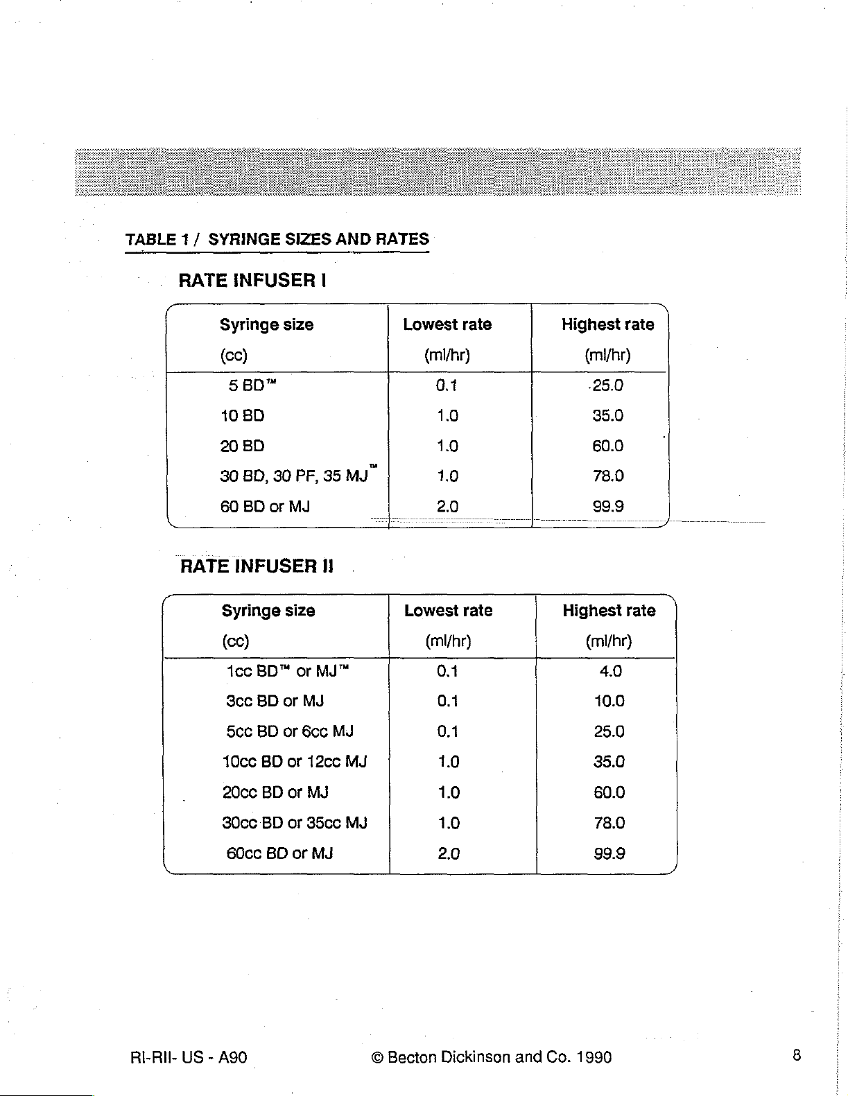
TABLE
1/
SYRINGE
SIZES
AND
RATES
RATE
RATE
INFUSER
Syringe
(cc)
5BD
10
BD
20
BD
BD,
30
60
BD
or
INFUSER
Syringe
(οο)
1ce
BD"
size
30
MJ
size
|
PF,
35
II
or
MJ"
MJ"
Lowest
(mi/hr)
0.1
1.0
1.0
10
2.0
Lowest
(ml/hr)
0.1
rate
rate
Highest
Highest
rate
(mhr)
.25.0
35.0
60.0
78.0
99.9
rate
(mi/hr)
4.0
ὴ
RI-RII-
US - A90
Scc
5cc
10cc
20cc
30cc
60cc
BD
BD
BD
BD
BD
BD
or
or
or
or
or
or
MJ
6cc
12cc
MJ
35cc
MJ
MJ
MJ
MJ
0.1
0.1
1.0
1.0
1.0
2.0
©
Becton
Dickinson
and
Co.
10.0
25.0
35.0
60.0
78.0
99.9
1990
ノ
NOTES
RI-RII-
US - A90
©
Becton
Dickinson
and
Co.
1990
|
9
SECTION
2
INSPECTION
The
following
the
unit's
case.
as a diagnostic
opened.
EQUIPMENT
Stopwatch
Pressure
Syringes : BECTON
BECTON
Three
UNIT
Record
REQUIRED
(the
meter
DICKINSON
way
stopcock
INITIALIZATION
PROCEDURE
inspection
This
procedure
procedure
all
data
longest
(0-50
DICKINSON,
with
TEST
procedure
at
for
test
psig
minimum
Cat.
luer
may
the
completion
this
section.
will
be
approx. 1 hour.
PLASTIPAK*
No
2804
fittings.
permits
be
range,
testing
used
0.1
extension
for
periodic
of
every
psig
3
set
of
the
RATE
inspection.
repair,
and
Resolution
resolution)
cc,
10
cc,
20
(60
inch
microbore
INFUSER
after
should
cc,
60
It
should
the
be
at
cc.
tubing
without
pump
opening
be
performed
has
been
least 1 second).
set).
1
install
2
Press
3
Press
Mİ
Beep
EE
The 4 indicator
* © Plastipak
RI-Ril-
US - A90
batteries.
the
POWER
POWER
is
is a TM
Do
not
place a syringe
OFF
button.
ON
button.
activated
Observe
once.
lights
of
Becton
Dickinson
the
flash
in
©
Becton
in
the
clamp.
following
sequence
seguence
and
Co.
Dickinson
and
of
events
Co.
:
1990
10
4
ME
The
lf
Display
M
Al
ος".
Press
INFUSE
Il
Observe
E
unit
unit
will
registers
legends
button
double
does
not
run a motor
all
"8",
except
with
"ML/HR*
no
syringe
beep.
infuse.
self-test
displays
turn
in
place.
for
"BD",
off
approximately
("PF")*,
and
the
40
"MJ",
upper
seconds.
"CC"
and
lower
and
"ML/HR"
segments
.
show
all
SYRINGE
1
Depress
Syringe
2
SWITCH
Depress
=
Upper
10’s
switch.
size
will
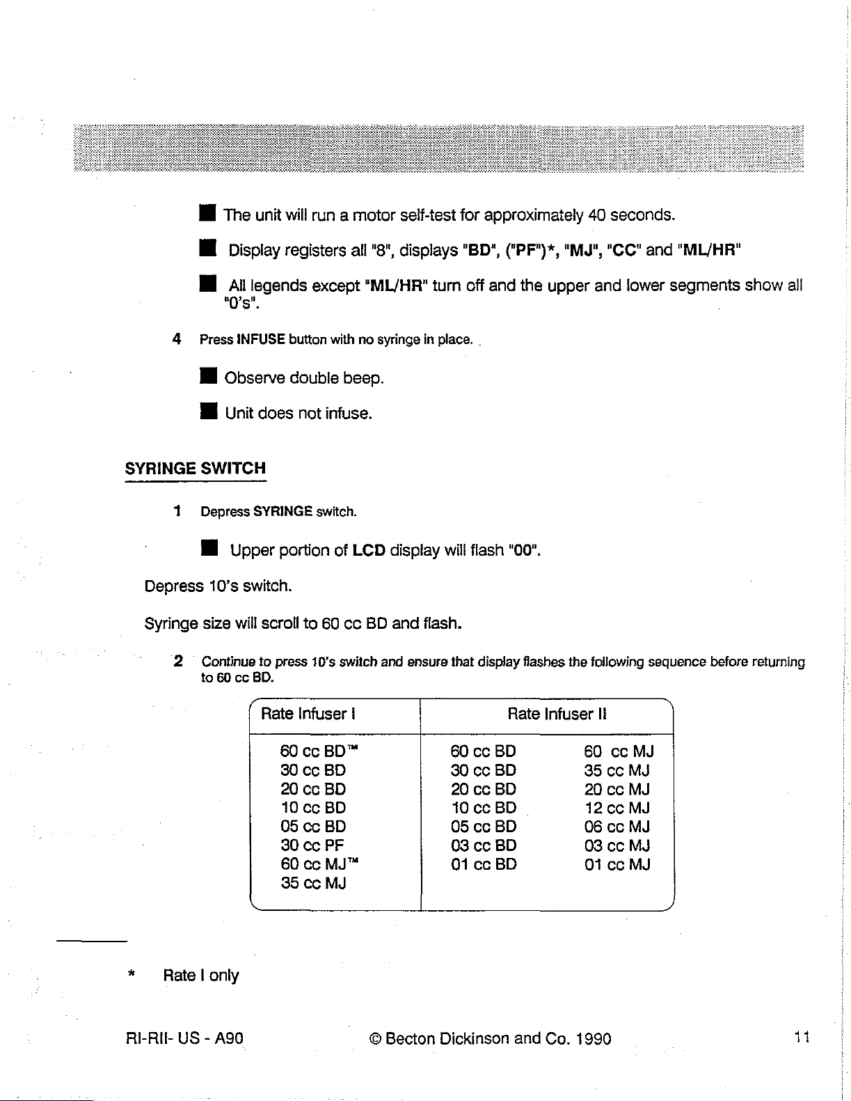
Continue
to
60
cc
SYRINGE
portion
scroll
to
press
BD.
(
Rate
60
30
20
10
05
80 cc
60
35
switch.
of
to
60
cc
10’s
switch
Infuser
cc
BD™
cc
BD
cc
BD
cc
BD
cc
BD
PF
cc
MJ™
cc
MJ
LCD
BD
|
display
and
and
ensure
will
flash.
that
60
30
20 cc
10
05
03 cc
01
flash
display
cc
BD
cc
BD
BD
cc
BD
cc
BD
BD
cc
BD
"00".
flashes
Rate
the
following
Infuser
60
35
20
12cc
06
03 cc
01
li
cc
cc
cc
ce
cc
sequence
MJ
MJ
MJ
MJ
MJ
MJ
MJ
)
before
returning
* — Rate | only
RI-RII-
US - A90
©
Becton
Dickinson
and
Co.
1990
11
3
Depress
Syringe
SYRINGE
size
will
switch
stop
flashing
RATE
LOW
SWITCH
1
Depress
Lower
2
Press
3
Ensure
4
Repeat
5
Set
6
Depress
VOLUME
1.
Placea
flange.
RATE
switch
portion
10's
rate
of
LCD
switch.
that digits 0 to 9 are
for 1's
CHECK
to
60.0
RATE
20
ce
switch
ml/hr.
switch.
/VOLUME
syringe
display
and
.1's
in
clamp.
will
flash.
displayed
switch.
DELIVERED
Set
syringe
for
tens
place.
plunger
CHECK
to 5 cc
.2
00.
Move
pusher
block
down
onto
syringe
2
3
RI-RII-
US - A90
With
syringe
Mİ
Press
milliliters
E
Low
Volume
II
After
seconds.
ll
Press
№
Press
Moving
the
size
set
and
hold
delivered.
the
Low
the
SYRINGE
STOP
pusher
infusion
up
to
"20 cc
VOL
Release
LED
will
Volume
to
top
BD"
and
rate
DEL
switch.
VOL
begin
switch.
switch.
position
©
Becton
LED
Beeping
will
to
begins
Motor
to
"60.0
ml/hr",
"mi/hr*
DEL
switch
flash
within 1 to 5 minutes.
to
flash, a double
will
will
stop
turn
off
LOW
Dickinson
press
will
stop.
and
VOLUME
and
Co.
INFUSE
change
beep
infusion
LED.
1990
switch.
to
"mi".
LED
will
be
will
LCD
heard
turn
will
display
every
off.
5
12
OCCLUSION
1
2
(1
NOTE:
TEST
Turn
on
pressure
Place
an
unused 5 cc
pusher
syringes
block.
with
meter.
syringe
Do
not
push
abnormally
down
filled
with
on
the
high
5.0
cc + .2
syringe
using
friction
should
cc
of
pusher
water
into
block; a loose
not
be
used.
position
mounting
in
the
clamp
is
desired.
block
and
Depress
3
4
Set
Depress
Depress
Set
Depress
Connect
2804)(See
10
With
the
11
12
SYRINGE
syringe
SYRINGE
RATE
rate
to
RATE
the
the
system
released
Depress
Blinking
before
vent
27.0
(all
valve.
INFUSE
ATTENTION
size
switch.
25.0
mi/hr.
switch
pressure
FIG.
2).
air
is
PSIG.
to 5 cc
BD
meter
vented,
out
of
switch.
LED,
Minimurn
to
advance
the
system)
and
trigger
the
the
"Occ"
pressure
syringe
pusher
and
zero
ste
25
e
will
display,
through a three-way
toward
relative
mijir
dc
should
the
the
pressure
alarm
be
9.9
clamp
aq
‘
beeps
PSIG.
valve
until
is
applied
-
and
Record
and a BD
two
or
to
BVO
the
unit
pressure
three
the
shuts
extension
drops
pressure
psi
down
reading
set
(NO.
of
water
are
meter.
automatically
and
Close
results.
13
14
15
Ri-RIL-
US - A90
Depress
Repeat
"60
beeps,
pressure
Depress
STOP
steps 3 through
cc
BD" and
and
should
POWER
INFUSION.
rate
unit
shut
be
OFF.
to
down)
5.5
Alarm
12
using a 60
"99.0
PSIG.
bå
©
will
mi/hr’.
The
should
Record
60
GI
ml
Becton
stop
and
ATTENTION
cc
syringe
occlusion
be
activated
pressure
<
reading
SS
Ar
Dickinson
filled
with
alarms
before
and
and
LED
will
60 cc + 0.5
(blinking
the
results.
-
Co.
ATTENTION
pressure
ро
1990
stop
flashing.
mi
reaches
of
water.
296
Set
LED,
12.0
syringe
multiple
PSIG.
Minimum
size
alarm
to
13
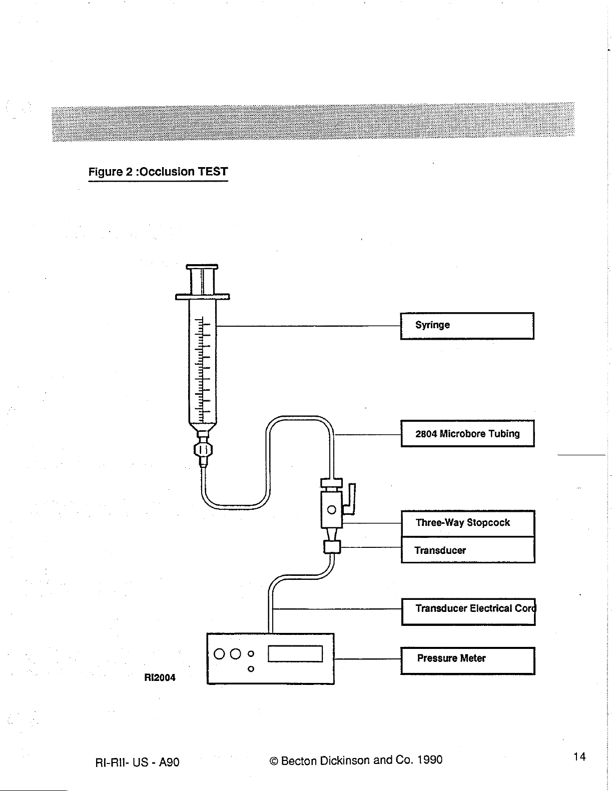
Figure 2 :Occlusion
TEST
Syringe
2804
Microbore
Tubing
RE-RII-
US
RI2004
Becton
A90
-
©
Dickinson
and
Three-Way
Transducer
Transducer
Pressure
1990
Co.
Stopcock
Electrical
Meter
14
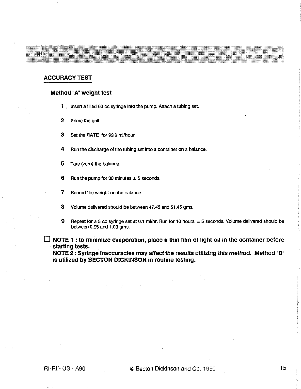
ACCURACY
TEST
Method
1
2
"A"
weight
Insert a filled
Prime
Set
the
Run
the
Tare
(zero)
Run
the
Record
Volume
Repeat
between
60 cc
the
unit.
RATE
discharge
the
pump
the
weight
delivered
for a 5
0.95
test
syringe
for
99.9
of
the
balance.
for
30
minutes + 5
on
should
cc
syringe
and
1.03
into
mi/hour
tubing
the
balance.
be
between
set
gms.
the
pump.
set
into a container
seconds.
47.45
at
0.1
mi/hr.
Attach a tubing
on a balance.
and
51.45
gms.
Run
for
10
hours + 5
set.
seconds.
Volume
delivered
should
be
[
NOTE
starting
NOTE
is
utilized
RI-Ril-
US - ASO
1:
to
tests.
2:
Syringe
by
minimize
inaccuracies
BECTON
evaporation,
may
DICKINSON
©
Becton
place a thin film
affect
in
the
results
routine
testing.
Dickinson
and
of
light
oil
utilizing
Co.
1990
in
this
the
container
method.
before
Method
"B"
15
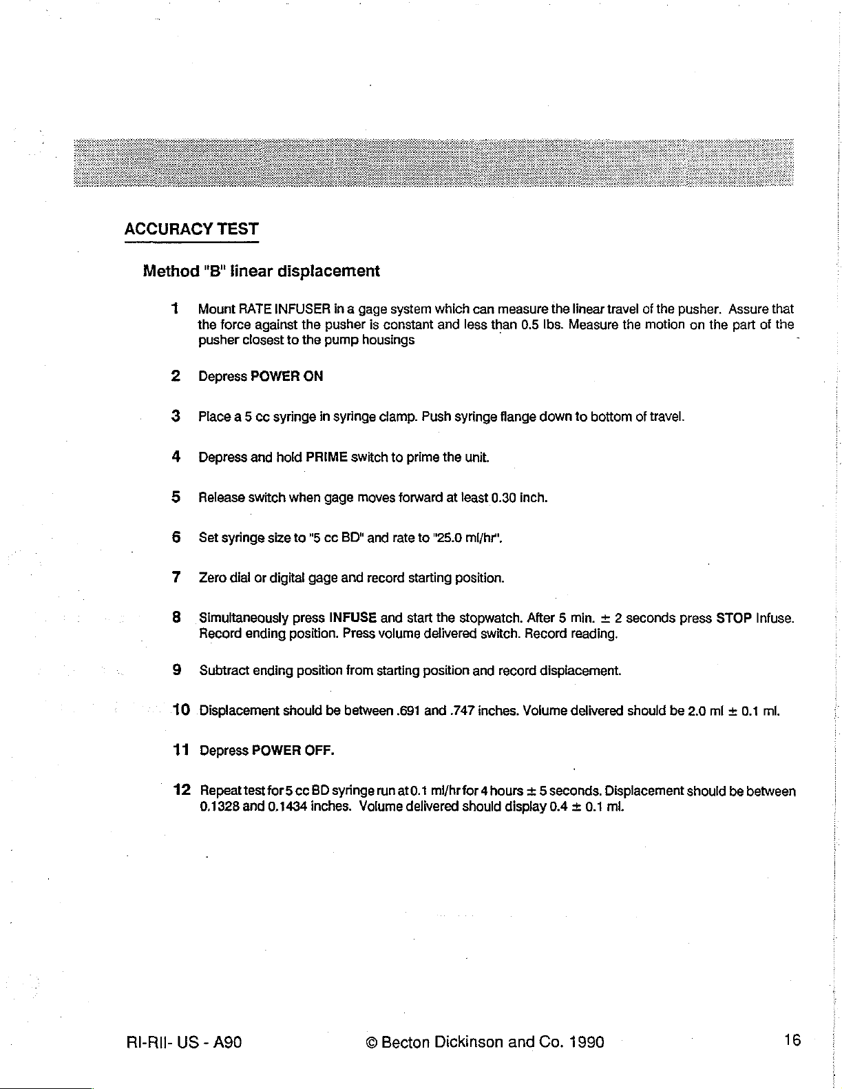
ACCURACY
Method
1
2
3
4
5
6
7
8
TEST
"B"
linear
Mount
the
force
pusher
Depress
Place
a5
Depress
Release
Set
syringe
Zero
dial
Simultaneously
Record
displacement
RATE
INFUSER
against
closest
POWER
ce
syringe
and
hold
switch
size
or
digital
ending
to
when
in a gage
the
pusher
the
pump
ON
in
syringe
PRIME
gage
to
"5
cc
BD"
gage
and
press
INFUSE
position.
Press
is
constant
housings
clamp.
switch
moves
and
record
and
volume
system
Push
to
prime
forward
rate
to
starting
start
which
can
and
less
syringe
the
unit.
at
least
"25.0
ml/hr",
position.
the
stopwatch.
delivered
switch.
measure
than
0.5
Ibs.
flange
down
0.30
inch.
After 5 min. + 2
Record
the
linear
Measure
to
reading.
travel
the
bottom
of
the
motion
of
travel.
seconds
pusher.
on
the
press
STOP
Assure
part
of
Infuse.
that
the
-
9
10
11°
12
RI-Ril-
Subtract
Displacement
Depress
Repeat
0.1328
US - A90
ending
POWER
test
and
position
should
for5
cc
0.1434
be
OFF.
BD
syringe
inches.
from
starting
between
run
Volume
©
Becton
position
.691
and
at0.1
mi/hr
delivered
Dickinson
and
record
.747
inches.
for 4 hours + 5
should
display
and
displacement.
Volume
delivered
seconds.
0.4 +
Co.
1990
should
Displacement
0.1
ml.
be
2.0
should
ml + 0.1 ml.
be
between
16
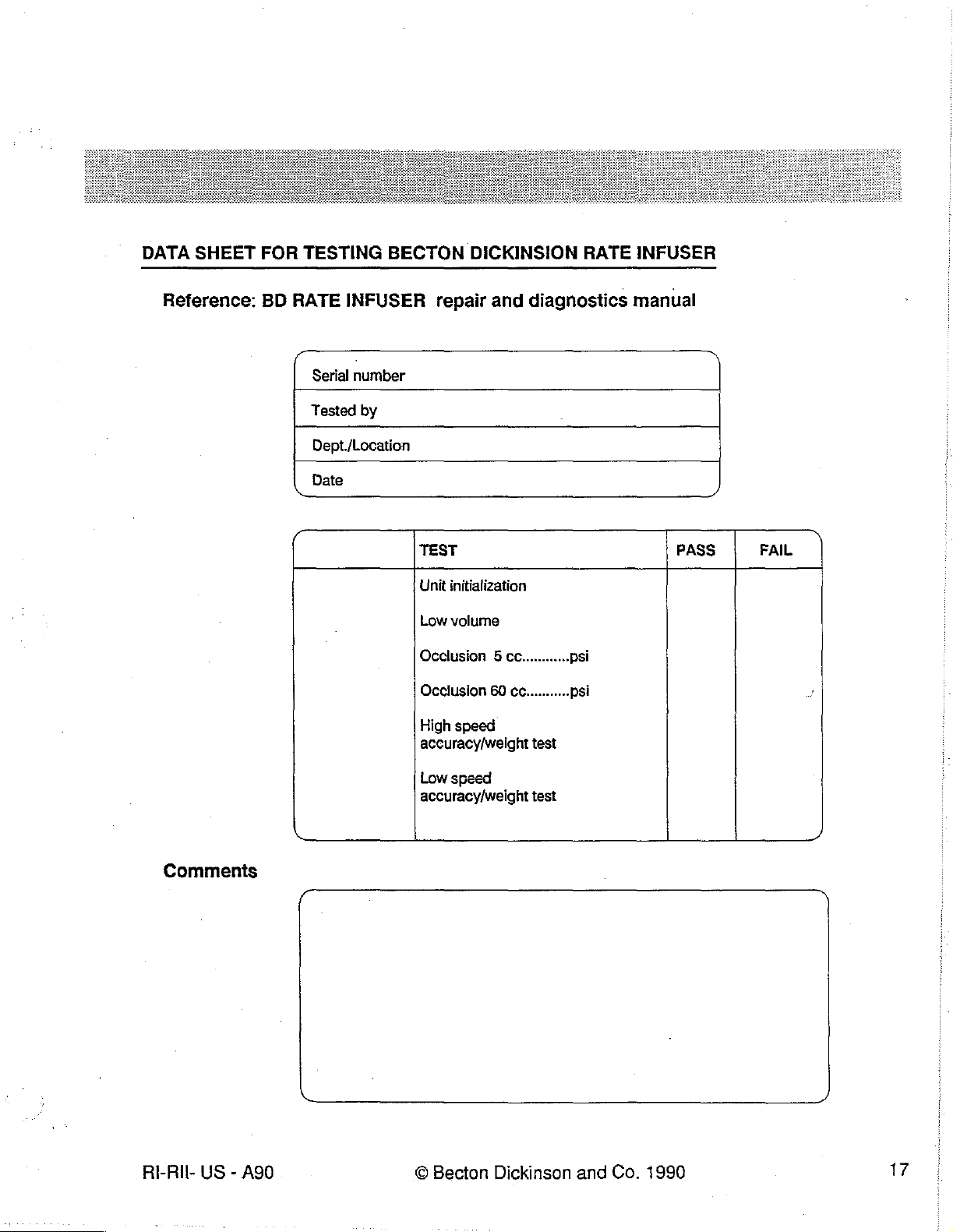
DATA
SHEET
FOR
TESTING
BECTON
DICKINSION
RATE
INFUSER
Reference:
BD
RATE
C
|
~
INFUSER
Date
.
Serial
number
Tested
Dept./Location
by
repair
TEST PASS
Unit
Low
Occlusion 5 cc............
Occlusion
High
accuracy/weight
and
diagnostics
initialization
volume
60
ce...........
speed
test
manual
N
psi
psi
)
FAIL
Commenis
RI-RIl-
US - A90
Low
speed
accuracy/weight
test
©
Becton
Dickinson
and
Co.
1990
NOTES
RI-Ril-
US - A90
©
Becton
Dickinson
and
Co.
1990
18
NOTES
RI-Ril-
US - A90
©
Becton
Dickinson
and
Co.
1990
19
SECTION
TROUBLESHOOTING
This
section
tion
of
aid
the
identified,
tion
on
provides
the
RATE
bioengineer
the
Assembly
ordering and
3
detailed
INFUSER . The
in
pinpointing
Replacement
procedures
information
regarding
troubleshooting
problems
section
for
replacement
and
of
this
the
guide
their
sources.
manual
and
repair.
mechanical
on
the
following
Once
(which
follows)
and
electrical
page
the
problem
provides
configura-
is
designed
has
informa-
to
been
RI-RII-
US - A90
©
Becton
Dickinson
and
Co.
1990
20
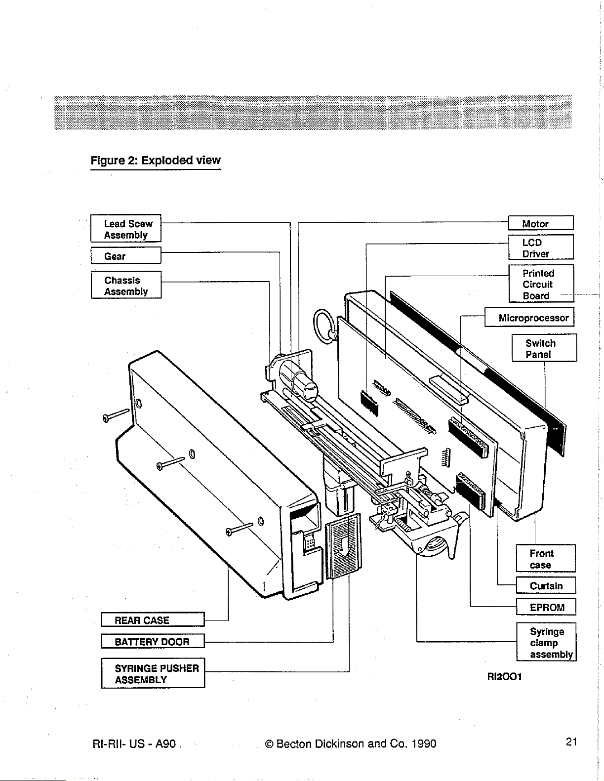
Figure
2:
Exploded
view
Lead
Scew
Assembiy
Ger
|
Chassis
Assembly
|
-
Motor
LCD
Driver
inted
Circuit
Board
Microprocessor
Switch
Panel
REAR
SYRINGE
ASSEMBLY
RI-RII-
US - A90
CASE
PUSHER
©
Becton
Dickinson
and
Co.
1990
RI2001
Syringe
clamp
assembly
21
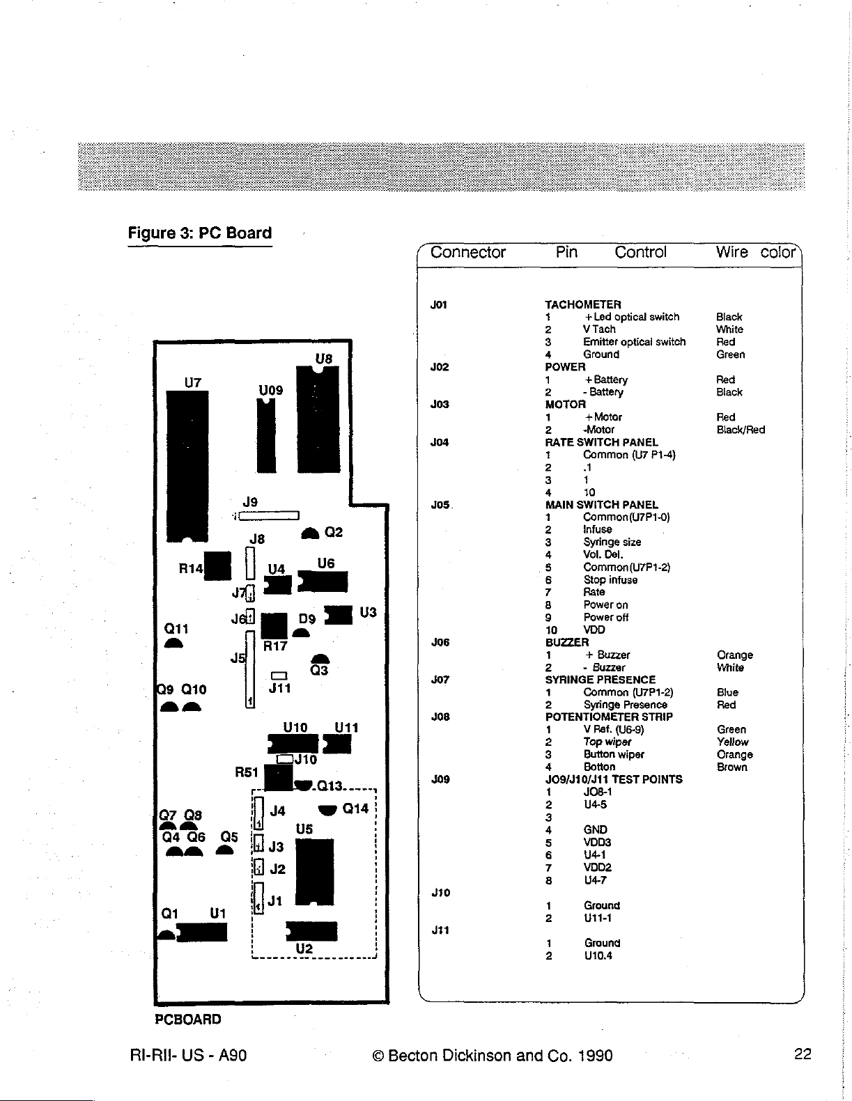
Figure
3:
PC
Board
(
Connector
Pin
Control
Wire
color)
J01
υ8
D9
a
o
a
=
3
Q13
2
U3
U11
7 1
J8
Ta
ma
圖
Q11
a
L
9
Q10
fa
U4
JA} р |
Jel]
R17
o
311
RSI
сто
ビ
a
U10
302
403
Jos
405
306
J07
Jos
409
TACHOMETER
1
+Led
2
V
3
4
РОМЕН
1
2
MOTOR
1
2
RATE
1
2
3
4
ΜΑΙΝ
2
3
4
5
6
7
8
9
10
BUZZER
1
2
SYRINGE
1
2
POTENTIOMETER
1
2
3
4
JO9/J10/J11
Tach
Emitter
Ground
+
Battery
-
Battery
+
Motor Red
„Motor
SWITCH
Common
A
1
10
SWITCH
Common(U7P1-0)
Infuse
Syringe
Vol. Del.
Common(U7P1-2)
Stop
Rate
Power
Power
VD
+
Buzzer
-
Buzzer
PRÉSENCE
Common
Syringe
V
Ref.
Top
Button
Botton
JO8-1
optical
optical
PANEL
(U7
PANEL
size
infuse
on
off
(U7P1-2)
Presence
(U6-9)
wiper
wiper
TEST
switch
switch
P1-4)
STRIP
POINTS
Black
White
Red
Green
Red
Black
Black/Red
Orange
White
Blue
Red
Green
Yellow
Orange
Brown
07
00
Gide
an
Qi
~
PCBOARD
RI-Ril-
US - A90
i]
! i
os
ls
a
| H
1
t 1
ἡ
9,131
U
| !
i !
|
nu
ya
A
U2
wa;
+
|
i
:
i
i
A
3 2
410
jn
©
Becton
Dickinson
and
3
6
7
8
1
2
1
Co.
us
NI
a
U4-1
von
U47
Ground
Ut
Ground
U10.4
1990
22
Figure
An
4:
electrical
Electrical
Schematic
schematic
has
been
enclosed
seperately
with
this
binder.
RI-RII-
US - A90
©
Becton
Dickinson
and
Co.
1990
23
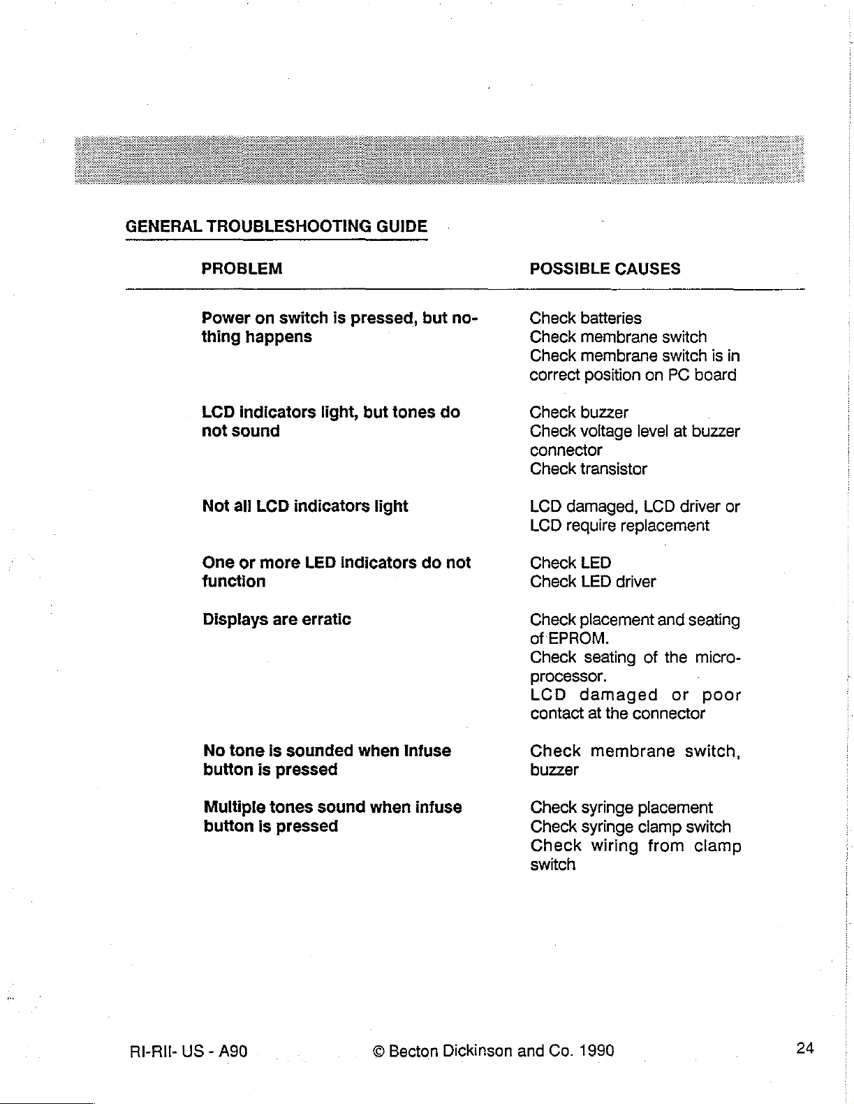
GENERAL
TROUBLESHOOTING
GUIDE
PROBLEM
Power
thing
LCD
not
Not
One
function
Displays
on
switch
happens
indicators
sound
all
LCD
indicators
or
more
are
is
pressed,
light,
LED
indicators
erratic
but
light
but
tones
do
no-
do
not
POSSIBLE
Check
Check
Check
correct
Check
Check
connector
Check
LCD
LCD
Check
Check
Check
of
Check
baiteries
membrane
membrane
position
buzzer
voltage
transistor
damaged,
require
LED
LED
placement
EPROM.
seating
CAUSES
switch
switch
on
PC
board
level
at
buzzer
LCD
driver
replacement
driver
and
seating
of
the
micro-
is
in
or
processor.
LCD
contact
damaged
at
the
connector
or
poor
RI-RII-
No
tone
button
Multiple
button
US - A90
is
sounded
is
pressed
tones
is
pressed
sound
when
when
©
Infuse
infuse
Becton
Dickinson
Check
buzzer
Check
Check
Check
switch
and
Co.
membrane
syringe
syringe
wiring
1990
switch,
placement
clamp
from
switch
clamp
24

PROBLEM
POSSIBLE
CAUSES
Attention
seconds
Infusion
mally
and
15
but
all
displays
minutes
alarm
of
starts
attention
sounds
starting
and
an
functions
alarm
flash,
within a few
infusion
nor-
sounds
after
approx.
Check
occlusion;
circuit
ger
with
just
Indicates
drive
perly.
train;
and
train.
syringe
and
driver
potentiometer
clamp
is
not
Check
Check
its
engagement
for
presence
Check
wiper;
wiper
occlusion
Check
and
strip;
assembly.
that
mechanical
functioning
motor
plunger
plun-
contact
and
drive
driver
with
drive
of
Ad-
pro-
RI-RII-
US - A90
.
©
Becton
Dickinson
and
Co.
1990
25


NOTES
RI-Ril-
US - A90
©
Becton
Dickinson
and
Co.
1990
26

SECTION
4
COMPONENTS
In
order
be
recommended
are
should
[)
NOTE:
when
SPARE
to
opened.
performed
be
itis
closing
PARTS
Descripion
Front
Pusher
AND
ASSEMBLY
replace
The
performed
very
any
batteries
that
the
on
every
important
the
unit.
LISTING
case
assembly
block
component
should
Alignment
unit
that
on
every
to
assembly
REPLACEMENT
or
assembly
be
removed
Test
Procedure
is
opened.
unit
after
it
avoid
pinching
Rate
Catalog
8880
8851
prior
In
has
been
infuser
(except
addition,
any
for
to
opening
and
the
ail
opened.
wires
!
N°
the
instruction
the
Occlusion
the
test
between
Rate
Catalog
8833
8837
label)
pump
procedures
the
Infuser
case.
Adjustment
studs
or
li
N°
the
unit
must
ft
is
strongly
Procedure
(Section
case
halves
5)
,
RI-Ril-
US - A90
LCD
display
Curtains
Rear
case
Chassis
motor,
and
optical
Motor
PC
with
board - revision 3 with
driver
(2)
assembly
assembly
encoder
switch
gear
gear,
EPROM
Optical
switch
with
LCD
©
Becton
8882
8853
8884
8885
8886
8887
8888
(rev.
8889
Dickinson
5)
and
Co.
8882
8853
8884
8838
8886
8887
8834
8889
1990
(rev.
1)
27

Descripion
Rate
infuser
|
Rate
Infuser
II
Encoder
Microprocessor
Wired
Battery
Split
Rear
Clamp
Buzzer
Crystal
Diagnostic
(this
LCD
gear
assembly
battery
door
ring
instruction
block
for
manual)
dispiay
terminals
with
retainer
assembly
PC
and
board
label
repair
manual
8890
8891
8863
8892
8865
8893
8894
8867
8872
8896
8881
(rev.
1)
8890
8891
8863
8892
8865
8835
8836
8867
8872
8896
8881
(rev.
0)
See
the
following
different
RI-Ril-
versions
US - A90
pages
of
the
for
information
RATE
INFUSER.
©
Becton
on
how
Dickinson
to
order
and
the
Co.
correct
1990
parts
for
the
28

HOW
TO
ORDER
DESCRIPTION
8833
8834
8835
8836
8837
8838
Front
(Rate
EPROM-
(Rate
Rear
Revision 0 (Rate
Clamp
(Rate
Pusher
(Rate
Chassis
encoder
case
assembly
Infuser
Infuser
Instruction
block
il
Only)
Revision
ll
Only}
Label-
assembly)
1
Infuser
Infuser l Only)
block
Infuser
assembly
I!
Only)
assembly
gear,
and
Il
with
motor,
optical
Only)
REQUIRED
Comes
door,
with
Does
label
Does
label.
tion
tion
screws.
instruction
not
not
Does
Does
not
label
not
label
INFORMATION
with
curtains,
Does
include
include
come
come
battery
not
label
instruction
instruction
with
instruc-
with
instruc-
come
switch
(Rate
Infuser
II
Only)
RI-RI
8851
US - A90
Pusher
(Rate
Infuser | Only)
block
assembly
©
Becton
Dickinson
Does
tion
and
label
Co.
not
1990
come
with
instruc-
29

DESCRIPTION
REQUIRED
INFORMATION
8853
8863
8865
8867
Curtains
Wired
Split
Buzzer
battery
ring
(2)
with
terminals
Retainer
Does
tion
not
label
Does
label
Does
label.
Does
label
not
not
not
come
with
include
include
include
instruc-
instruction
instruction
instruction
RI-RII-
US - A90
©
Becton
Dickinson
and
Co.
1990
30

DESCRIPTION
REQUIRED
INFORMATION
8880
8881
8882
8884
8885
8886
Front
(Rate
case
infuser I Only)
LCD
LCD
display
Rear
case
Chassis
encoder
switch
(Rate
Motor
Infuser | Only)
with
assembly
driver
assembly
assembly
gear,
and
encoder
with
optical
gear
motor,
Comes
door,
with
Does
tion
Does
tion
Comes
come
Does
label
screws.
instruction
not
label.
not
label
with
Comes
screw
clude
instruction
with
curtains,
come
come
with
screws.
instruction
not
include
with
motor
for
gear.
Does
not
label.
with
with
Does
instruction
mounting
Does
label.
battery
come
instruc-
instruc-
not
label
not
in-
RI-RII-
US - A90
8887
8888
PC
board - revision
EPROM
(Rate
-
Revision
Infuser I Only)
©
Becton
3
5
Dickinson
Does
label.
and
Co.
not
1990
include
instruction
31

DESCRIPTION
REQUIRED
INFORMATION
8889
8890
8891
8892
8893
8894
8895
Optical
Encoder
Microprocessor
Battery
Rear
revision
(Rate
Clamp
(Rate
Crystal
switch
gear
door
instruction
1
Infuser | Only)
block
Infuser | Only)
for
assembly
label
assembly)
PC
board
Does
label
Does
label.
Does
label.
Includes
strip.Does
tion
Replace
Does
label.
wire
Does
label
not
include
not
include
not
include
not
label.
all
not
include
Comes
and
wiper.
not
include
copper
previous
instruction
instruction
instruction
contact
include
instruc-
revisions.
instruction
with
separate
instruction
Lİ
TO
ORDER
Call
Lİ
For
INFUSION
RI-RII-
US - A90
SPARE
your
local
technical
SYSTEMS
PARTS
authorized
information
TECHNICAL
FOR
YOUR
BECTON
regarding
Service
©
Becton
RATE
DICKINSON
spare
parts
at
Dickinson
INFUSER:
INFUSION
and
repair,
SYSTEMS
1-800-232-8666
and
Co.
1990
dealer.
call
BECTON
or
1-201-633-5500
DICKINSON
32

FRONT
1
Front
2
Curtains
1
Battery
3
Gase
CASE
ASSEMBLY : CATALOG
Materials
case
assembly
door
with
screws
Procedure
positive
battery
N°
8880
terminal
(Rate
Infuser 1 Only)
Remove
in
procedure. A heat
With
Remove
Remove
Replace
Remove
optical
Unscrew
front
Attach
Reinstall
order
the
switch
case.
the
the
instruction
to
prepare
pump
lying
the
back
the
buzzer
the
curtain
the
chassis
connector,and
the 3 screws
curtain
the
PC
the
gun
on
case.
connector
on
by
that
to
the
board
label
from
the
case
for
the
is
useful
in
removing
its
front
face,
and
the
the
back
case
disconnecting
the
resistor
hold
the
PC
new
front
case.
into
the
front
back
case.
replacement
the
remove
and
power
set
the
motor,
the
connector.
the
strip
board
in
case.
The
label
label
that
label.
Remove
three
back
back
case
the
switch
connector.
place
and
should
be
will
be
batteries.
case screws.
aside.
panel
connectors , the
Set the
set
the
chassis
PC
removed
applied
aside.
board
cleanly
at
the
aside.
and
completion
clamp
Discard
completely
of
connectors
the
damaged
this
,
10
11
12
13
RI-RII-
US - A90
Reinstall
Reconnect
the
connector,
Proceed
Reconnect
to
chassis.
the
motor
connector,
and
the
resistor
section 5 for
the
buzzer
connector
the
strip
connector
alignment
and
©
Becton
switch
and
occlusion
the
power
Dickinson
panel
.
connector
connector,
adjustment
.
and
Co.
the
clamp
test
procedures.
1990
connector,
the
optical
switch
33

14
Attach
(1
CAUTION : when
care
not
to
15
Test
16
Attach a new
the
back
bend
in
or
accordance
instruction
case
while
holding
reattaching
crimp
the
with
inspection
label*
the
battery
the
back
switch
and replace
panel
procedure
door
in
case
use
ribbon
in
Section
batteries.
its
channel
the
cables
2.
for
three
or
positioning.
screws
any
provided
other
wires.
and
take
*
Order
RI-RII-
US
separately
-
A90
©
Becton
Dickinson
and
Co.
1990
34

Split
1
Spiit
ring
and
Materials
ring
Procedure
retainer : Catalog
with
ring
retainer
i
N°
8865
O
1 | Remove
2 | With
3
4
5 | Attach
CAUTION
panel
6
7
the
instruction
in
order
to
prepare
procedure. A heat
the
pump
lying
Remove
Place
ribbon
Testin
Attach a new
the
the
ring
the
back
:
When
cables
accordance
back
retainer
reattaching
instruction
the
gun
on
case.
case
while
or
any other
with
label
from
case
is
useful
its
front
Remove
between
holding
inspection
label*
the
back
for
the
replacement
in
removing
face,
remove
any
broken
the
two
the
the
back
wires.
procedure
and repiace
case.
the
the
pieces
case
halves.
battery
door
case,
batteries.
The
label
label.
three
take
in
Section
label
Remove
back
of
the
in
its
care
should
that
will
batteries.
case
ring
retainer
channel
not
2.
be
removed
be
applied
screws.
from
inside
for
positionning.
to
bend
cleanly
at
the
the
or
crimp
and
completely
completion
pump.
the
of
this
switch
*
Order
RI-Ril-
US - A90
separately
©
Becton
Dickinson
and
Co.
1990
35

Curtains : Catalog
Materials
2
Curtains
Procedure
1°
Remove
in
procedure. A heat
2
Remove
3
With
4
Replace
5
Replace
order
the
the
to
the
pump
the
the
N°
8853
instruction
prepare
three
curtain on
curtain
the
gun
back
lying
on
on
label
case
is
useful
case
its
front
the
back
the
front
from
the
for
the
in
removing
screws.
face,
case
case.
back
case.
The
replacement
the
label.
remove
and
set
the
the
back
back
label
should
label that
Remove
case.
case
aside.
be
removed
will
be
applied
batteries.
cleanly
at
the
and
completely
completion
of
this
6 | Attach
CI
CAUTION : When
panel
ribbon
7
Testin
8
Attach a new
the
case
halves
reattaching
cables
accordance
instruction
or
with
any
while
holding
the
other
inspection
label*
and
the
battery
back
case, take
wires.
procedure
replace
door
in
Section
batteries.
in
its
care
2.
channel
not
for
positionning.
to
bend
or
crimp
the
switch
RI-RIf-
US - A90
©
Becton
Dickinson
and
Co.
1990
36

Rear
1
2
3
case
assembly : Catalog
Materials
Rear case
Curtains
Nº 6 Case
Procedure
1
Remove
in
order
procedure. A heat
2
With
3
Remove
assembly
screws
the
instruction
to
prepare
the
pump
and discard
gun
lying
the
is
on
the
N°
8884
label
from
case
for
useful
its
front face,
damaged
the
back
the
replacement
in
removing
remove
back
case.
the
case.
The
label.
the
three
label
label
Remove
back
should
that
will
case
be
removed
be
applied
batteries.
screws.
cleanly
at
the
and
completely
completion
of
this
(1
*
4 | Replace
5
6
CAUTION
pane!
7
8
Order
the
Connect
Attach
ribbon
Testin
Attach a new
the
the
:
When
cables
accordance
separately
curtain
case
on
buzzer
halves
reattaching
or
with
instruction
the
new
connector
while
holding
any
other
inspection
label*
back
case
and
power
the
the
back
wires.
procedure
and replace
and
on
connector
battery
door
case,
in
batteries.
the
front
to
the
in
its
take
care
Section
case.
PC
channel
not
2.
board.
for
to
bend
positioning.
or
crimp
the
switch
RI-Ril-
US
-
A90
©
Becton
Dickinson
and
Co.
1990
37

Fig
5:Rear
Case
RI2005
RI-RII-
US - A90
©
Becton
Dickinson
and
Co.
1990
38
_

Battery
Materials
1
Battery
Procedure
door : Catalog
door
with
positive
N°
8892
battery
terminal
1 . Remove
in
procedure. A heat
2
With
3
Remove
4
Altach
[I
CAUTION : When
panel
5
6
ribbon
Test
Attach
the
order
to
the
pump
the
the
cables
in
accordance
the
instruction
prepare
back
case
the
gun
lying
case.
halves
on
reattaching
or
with
new
instruction
label
fram
case
is
useful
its
front
while
holding
any
other
inspection
label*
for
in
face,
the
the
and
the
back
replacement
removing
remove
the
new
back
case, take
wires.
procedure
replace
case.
The
label that
the
label.
the
three
battery
in
Section
batteries.
label
Remove
back
door
care
2.
should
will
batteries.
case
in
its
channel
not
be
removed
be
applied
screws.
for
to
bend
cleanly
at
positioning.
or
the
completion
crimp
and
completely
of
the
switch
this
*
Order
RI-Ril-
separately
US - A90
©
Becton
Dickinson
and
Co.
1990
39

Wired
1
Wired
battery
terminal : Catalog
Materials
battery
Procedure
terminal
N°
8863
Remove
in
procedure. A heat
With
Remove
Remove
Remove
if
and
Slide
the
the
Pinch
the
the
order
to
the
pump
the
the
the
necessary,
the
back
the
positive
end
clip
two
case
the
metal
battery
instruction
prepare
lying
back
buzzer
damaged
trim
case.
up
and
halves.
contact
compartment
the
gun
on
case.
connector
battery
the
back
Do
end
of
over
label
case
is
useful
its
front
case
not
crimp
the
the
shoulder
on
the
spring.
from
the
for
the
in
removing
face,
and
the
terminal
so that
the
battery
terminal
at
negative
back
case.
replacement
the
remove
terminai’s
power
and
there
the
connector
discard.
is
clearance
onto
the
far
side
end
of
The
label
label.
three
metal
its
of
the
the
battery
label
should
that
will
Remove
back
case
.
between
contact.
mounting
mounting
terminal
be
removed
be
applied
batteries.
screws.
the
positive
location
as
this
and
of
will
slide
cleanly
at
the
end
the
back
cause
it
onto
of
and
completely
completion
the
battery
case.
interference
the
Do
post
terminal
not
between
portion
of
this
slide
of
9
Proceed
10
Reconnect
11
Attach
El]
CAUTION : When
panel
RI-RII-
ribbon
12
Test
US - A90
to
section 5 for
the
the
back
cables
in
accordance
alignment
buzzer
case
connector
while
holding
reattaching
or
any
other
with
inspection
and
the
wires.
©
Becton
and
occlusion
the
power
the
battery
back
case,
procedure
Dickinson
adjustment
connector
door
in
take
in
Section
and
.
its
channel
care
2.
Co.
test
procedures.
for
not
to
1990
positioning.
bend
or
crimp
the
switch
40

13
Attach a new
instruction
label*
and
replace
batteries.
RI-RII-
US - A90
*
Order
separately
©
Becton
Dickinson
and
Co.
1990
41

Instruction
Materials
1
Instruction
Procedure
1
Remove
in
procedure. A heat
2
Aïttachthe
label
label
order
revision
the
instruction
to
prepare
new
instruction
0:
the
gun
Catalog
label
from
case
for
is
useful
label*.
N°
the
the
replacement
in
removing
8893
back
(Rate
case.
the
label.
infuser
The
label
label
Remove
should
that
will
Il
Only)
be
removed
be
applied
batteries.
cleanly
at
the
and
completely
completion
of
this
*
Order
RI-RII-
separately
US - A90
©
Becton
Dickinson
and
Co.
1990
42

PC
board
Materials
1
PC
Procedure
revision 3 :
board
Catalog
N°
8887
Remove
in
procedure. A heat
With
Remove
Remove
Remove
switch
Unscrew
Remove
EPROM's
Discard
Install
the
the
order
to
the
pump
the
the
the
connector,
the
the
the
screws.
instruction
prepare
lying
back
buzzer
chassis
the 3 screws
EPROM
pins.
Check
damaged
new
PC
label
from
the
the
case
for
the
gun
is
useful
in
removing
on
its
front
face,
case.
connector
by
the
clamp connectors , and
that
from
the
PC
board
and
the
disconnecting
hold
the
PC
the
damaged
EPROM
board.
into
orientation.
the
front
back
case.
replacement
the
label.
remove
power
the
the
connector
motor
the
board
in
PC
board
case.
Do
not
The
label
should
label
that
will
Remove
three
back
case
.
connector , the
resistor
place
and
and
install
forget
strip
set
the
to
use
be
removed
be
applied
batteries,
at
screws.
switch
panels
connector . Set
front
case
aside.
it
in a new
insulating
PC
washers
cleanly
the
connectors , the
the
board.
and
completely
completion
chassis
Do
under
aside.
not
the
bend
of
this
optical
heads
the
of
10
11
12
13
14
RI-RII-
US - A90
Reinstall
Reconnect
the
chassis.
the
connector , and
Proceed
Reconnect
Attach
to
section 5 for
the
the
back
motor
connector , the
the
resistor
buzzer
case
connector
while
strip
connector
alignment
and
holding
©
Becton
switch
and
occlusion
the
power
the
battery
Dickinson
panels
.
connector
door
connectors , the
adjustment
test
.
in
its
channel
and
Co.
1990
clamp
connector
procedures.
for
positioning.
,the
optical
switch
43

LJ
CAUTION:
-
panel
ribbons
15
Test
16
Attach a new
When
cables
in
accordance
reattaching
or
any
with
inspection
instruction
label*
the
back
other
wires.
procedure
and replace
case,
take care
in
section
batteries.
2.
not
to
bend
or
crimp
the
switch
* — Order
RI-RII-
US - A90
separately
©
Becton
Dickinson
and
Co.
1990
44

EPROM
1
Programmed
revision 5 :
Materials
Procedure
1
Remove
in
order
procedure. À heat
2
With
the
3
Remove
4
Remove
5
Remove
switch
connector,
Catalog
EPROM
the
instruction
to
prepare
pump
lying
the
back
the
buzzer
the
chassis
N°
label
the
case
gun
is
useful
on
its
front face,
case.
connector
by
disconnecting
the
clamp
8888
(Rate
from
the
for
the
in
removing
and
the
connector,
Infuser I Only)
back
case.
The
replacement
the
label.
remove
power
the
motor
and
the
three
connector
the
resistor
label
should
label
that
will
Remove
back case screws.
.
connector,
the
strip
connector.
be
removed
be
applied
batteries.
switch
panels
cleanly and
at
connectors,
Set the
the
completion
chassis
completely
the
optical
aside.
of
this
6
Pry
7
install
orientation
8
Reinstall
9
Reconnect
connector,
10
Proceed
11
Reconnect
12
Attach
U
CAUTION : When
panei
ribbon cables
13
Test
up
the
damaged
the
new
indicator
the
chassis.
the
and
to
section 5 for
the
the
back
in
accordance
EPROM
EPROM
making
marking
motor
connector,
the
resistor
buzzer
case
strip
alignment
connector
while
holding
reattaching
or
any
other
with
inspection
and
discard.
sure
on
the
the
connector
and
the
back
the
orientation
PC
board).
switch
and
the
panels
.
occlusion
the
power
battery
case,
wires.
procedure
is
correct
Do
not
bend
connectors,
adjustment
connector.
door
in
its
take
care
in
section
(note
the
the
test
channel
not
2.
the
notch
EPROM’s
clamp
connector,
procedures.
for
positioning.
to
bend
on
pins.
or
the
EPROM
the
crimp
and
optical
the
switch
switch
the
RI-RII-
US - A90
©
Becton
Dickinson
and
Co.
1990
45

14
Attach a new
instruction
label*
and
replace
batteries.
*
RI-RII-
Order
US - A90
separately
©
Becton
Dickinson
and
Co.
1990
46

Microprocessor : Catalog
Materials
1
Microprocessor
Procedure
1
Remove
in
procedure. A heat
2
With
3
Remove
4
Remove
5
Pry
order
the
up
the
to
pump
the
the
the
prepare
damaged
instruction
lying
back
case.
buzzer
N°
8891
fabel
from
the
case
for
gun
is
useful
on
its
front
connector
microprocessor
the
the
in
removing
face,
and
back
replacement
remove
the
power
and
discard.
case.
The
the
label.
the
three
connector
label
label
Remove
back
should
that
case
.
be
will
be
applied
batteries.
screws.
removed
cleanly
at
the
and
completely
completion
ot
this
6 Install
cessor
7.
Proceed
8
Reconnect
9
Attach
CJ
CAUTION : When
panel
*
ribbon
10
Test
31
Attach a new
Order
separately
the
new
and
the
to
section 5 for
the
the
back
cables
in
accordance
microprocessor,
orientation
buzzer
case
indicator
alignment
connector
while
holding
reattaching
or
any
other
with
inspection
instruction
label*
making
the
and
sure
making
and
occlusion
and
the
the
battery
back
wires.
procedure
replace
the
orientation
on
the
adjustment
power
connector
door
case,
take
in
Section
batteries.
PC
board).
in
its
is
.
channel
care
2
correct
Do
not
test
procedures.
for
not
to
(note
the
notch
bend
the
microprocessor's
positioning.
bend
or
crimp
on
the
micropro-
the
pins.
switch
RI-RII-
US - A90
©
Becton
Dickinson
and
Co.
1990
47

LCD:
1
Catalog
Materials
LCD
display
Procedure
N°
8881
Remove
in
order
the
instruction
to
prepare
procedure. A heat
With
the
pump
lying
Remove
Remove
Remove
switch
Unscrew
Unsolder
Install
Reinstall
the
back
the
buzzer
the
chassis
connector,
the 3 screws
the
damaged
the
new
LCD
the
PC
board.
tabel
the
case
gun
is
useful
on
its
case.
connector
by
disconnecting
the
clamp
that
LCD
being
Do
from
the
for
the
in
removing
front
face,
and
connector,
hold
the
out
of
carreful
not
not
forget
back
case.
replacement
the
remove
the
power
the
motor
and
PC
board
its
socket
to
heat
the
insulating
The
label
label.
the
three
connector
connector,
the
resistor
in
place
and
discard.
up
the
washers.
label
that
Remove
back
.
strip
and
PC
board.
shauld
will
be
be
applied
removed
batteries.
case screws.
the
switch
connector . Set
set
the
front
panels
case
cleanly
at
the
completion
connectors,
the
chassis
aside
and
completely
the
aside.
of
this
optical
10
11
12
13
14
RI-RII-
Reinstall
Reconnect
connector
Proceed
Reconnect
Attach
US - A90
the
chassis.
the
and
to
Section 5 for
the
the
back case
motor
connector , the
the
resistor
buzzer
connector
while
strip
connector
alignment
and
holding
©
Becton
switch
and
occlusion
the
the
battery
Dickinson
panels
.
power
connectors , the
adjustment
connector
door
in
and
.
its
channel
Co.
clamp
test
procedures.
for
1990
connector , the
positioning.
optical
switch
48

(1
CAUTION : When
panel
ribbon
15
Test
16
Attach a new
cables
in
accordance
instruction
reattaching
any other
with
inspection
fabel*
the
back
wires.
and
case,
procedures
replace
batteries.
take care
in
Section
2.
not
to
bend
or
crimp
the
É
switch
*
Order
RI-RII-
US - A90
separately
©
Becton
Dickinson
and
Co.
1990
49

LCD
1
dispiay
Materials
LCD
display
Procedure
driver : Catalog
driver
N°
8882
Remove
in
procedure. A heat
With
Remove
Remove
Remove
switch
Unscrew
Desolder
Install
orientation
Clean
order
the
connector,
the
the
the
instruction
to
prepare
pump
lying
the
back
the
buzzer
the
chassis
the 3 screws
the
LCD
new
display
indicator
PC
board.
label
the
case
gun
is
on
its
case.
connector
by
disconnecting
the
clamp
that
driver
straight
driver,
marking
Install
from
for
useful
in
front
face,
and
connectors,
hold
making
on
the
new
the
the
removing
remove
the
the
PC
back
the
PC
LCD
back
case.
replacement
the
label.
the
power
connector
the
motor
and
the
board
in
out
of
its
socket
sure
the
orientation
board).
Take
driver.
The
label
label that
Remove
three
back
.
connector,
resistor
place
and
and
care
should
will
be
batteries.
case
screws.
the
switch
strip
connector . Set
set
the
front
set
it
aside.
is
correct
not
to
solder
be
removed
applied
case
(note
at
panels
the
aside.
the
notch
adjacent
cleanly
connectors,
the
completion
chassis
on
legs
or
and
the
pads
completely
of
this
the
optical
aside.
chip
and
together.
the
10
11
12
13
14
RI-Rit-
US - ASO
Reinstall
Reinstail
Reconnect
clamp
Proceed
Reconnect
the
the
connector , and
to
PC board
into
chassis.
the
motor
connector , the
the
section 5 for
the
buzzer
connector
the
front
resistor
alignment
and
©
Becton
case.
Do
switch
strip
connector
and
occlusion
the
power
Dickinson
not
forget
panels
.
adjustment
connector
and
the
insulating
connectors , the
test
procedures.
.
Co.
1990
washers
optical
switch
connectors , the
50.

15
Attach
C]
CAUTION : When
pannel
ribbon cables
16
Test
17
Attach a new
the
back
reattaching
in
accordance
instruction
case
or
with
while
holding
the
any
other
inspection
label*
the
back
wires.
procedure
and
replace
battery
door
case,
in
batteries.
in
its
take
care
Section
2.
channel
for
not
positioning.
to
bend
or
crimp
the
switch
* > Order
RI-RII-
US - A90
separately
O
Becton
Dickinson
and
Co.
1990
-
51

Crystal:
Catalog
Materials
1
Quartz
Procedure
N°
crystal
8872
Remove
in
procedure. A heat
With
Remove
Remove
Remove
switch
Unscrew
Remove
Install
area
board
Reinstall
order
the
connector,
the
marked
and
the
instruction
to
prepare
pump
lying
the
back
the
buzzer
the
chassis
the 3 screws
the
damaged
new
crystal
on
the
the
support
the
PC board
label
the
case
gun
is
useful
on
its
case.
connector
by
disconnecting
the
clamp
that
crystal
with
PC
board.
wire
into
from
the
for
the
in
removing
front
face,
and
connectors,
hold
the
and
discard.
the
foam
The
facing
the
the
frant
back
case.
replacement
the
remove
the
power
the
motor
and
PC
board
Clean
towards
crystal
the
should
outside
case.
Do
The
label
label.
the
three
connector
connector,
the
resistor
in
place
all
contact
PC Board
lay
of
the
PC
not
forget
label
should
that
Remove
back
.
strip
and
set
and
flat
with
board.
the
be
removed
will
be
applied
batteries.
case
screws.
the
switchpanels
connector . Set
the
front
case
holes
by
desoldering.
the
body
the
terminals
Solder
insulating
in
washers.
at
aside.
of
the
facing
place.
cleanly
the
and
completion
connectors,
the
chassis
crystal
aligned
the
inside
completely
of
this
the
optical
aside.
within
of
the
the
PC
10
11
12
13
14
RI-Ril-
US - A90
Reinstall
Reconnect
connector , and
Proceed
Reconnect
Attach
the
chassis.
the
to
section 5 for
the
the
back
motor
connector , the
the
resistor
buzzer
case
connector
while
strip
connector
alignment
and
holding
©
Becton
switch
and
occlusion
the
power
the
battery
Dickinson
panels
.
adjustment
connector
door
connectors
test
.
in
its
channel
and
Co.
,the
optical
procedures.
for
positioning.
1990
switch
connector,
the
clamp
52

©]
CAUTION : When
panel
ribbon cables
15
Test
16
Attach a new
in
accordance
reattaching
or
any
other
with
inspection
instruction
label*
the
back
wires.
procedure
and replace
case,
take care
in
Section
batteries.
2.
not
to
bend
or
crimp
the
switch
*
Order
RI-RII-
US - A90
separately
©
©
Becton
Dickinson
and
Co.
1990
:
53

Buzzer : Catalog
Materials
1
Buzzer
Procedure
N°
8867
Remove
in
order
procedure. A heat
With
Remove
Remove
Pry up
Install
allows
slightly
Reconnect
7
Attach
(]
CAUTION : When
panel
ribbon
the
the
the
wires
melt
the
the
instruction
to
prepare
pump
lying
the
back
the
buzzer
old
buzzer
new
buzzer
to
be
the
mounting
the
buzzer
back
case
reattaching
cables
label
the
case
gun
is
useful
on
its
case.
connector
and
in
the
connected
connector
while
or
any
from
for
the
in
front
face,
and
discard.
alternate
to
PC board
posts
and
and
holding
the
other
the
back
replacement
removing
remove
the
power
mounting
secure
the
power
the
battery
back
case,
wires.
case.
The
label
the
label.
the
three
connector
located
properly.
the
buzzer.
connector
door
take
label
should
that
Remove
back
.
on
the
Use a flat-tipped
.
in
its
channel
care
be
will
be
batteries.
case
screws.
back
case.
for
not
to
removed
applied
Make
soldering
positioning.
bend
cleanly
at
the
sure
or
crimp
and
completely
completion
orientation
tool
or
equivalent
of
the
of
this
buzzer
to
switch
9
10
*
Order
RI-RII-
US - A90
Test
in
accordance
Attach a new
separately
with
inspection
instruction
label*
and
©
Becton
procedure
replace
batteries.
p
Dickinson
in
Section
2.
and
Co.
1990
54

Chassis
assembly
Materials
with
motor : Catalog
N°
8885
(Rate
Infuser
II
only)
Chassis
Procedure
[I
CAUTION : Do
spring
assembly
Remove
in
order
procedure. A heat
With
the
Remove
Remove
Remove
connectors,
chassis
Position
screw
should
with
the
instruction
to
prepare
pump
the
back
the
buzzer
the
damaged
the
aside
.
the
clamp
located
not
not
lying
clamp
on
compress
lie
motor,
label
the
case
gun
is
on
its
case.
connector
chassis
connector,
on
the
the
collar.
loose.
encoder
from
for
useful
in
front
face,
and
and
new
chassis
(See
the
gear,
the
back
the
replacement
removing
remove
the
power
motor
the
optical
so that
figure
8)
spring
and
optical
case.
The
label
label
the
label.
Remove
the
three
back
connector
by
disconnecting
switch
connector,
it
is
flush
when
tightening
switch.
should
that
case
.
with
the
be
removed
will
be
applied
batteries.
screws.
the
motor
and
the
chassis
the
cleanly
at
the
connector,
resistor
end
set
strip
bracket
screw;
and
completely
completion
the
switch
connector.
and
tighten
however,
of
this
panels
Set
the
the
set
the
7
8
9
10
11
RI-RII-
US - A90
Reinstall
Reconnect
connector , and
TheAlignmentand
5.
Reconnect
Attach
the
the
chassis.
the
motor
the
the
buzzer
back
case
connector , the
resistor
Occlusion
strip
Adjustment
connector
while
holding
©
switch
connector
and
the
the
Becton
panels
connectors , the
.
test
procedures
power
connector.
battery
door
Dickinson
in
its
and
should
be
channel
Co.
1990
clamp
connector , the
conducted
for
positioning.
at
this
point.
optical
switch
See
Section
55

[1
CAUTION:
panel
ribbon
12
Testin
13
Attach a new
When
reattaching
cables
accordance
instruction
or
with
any
the
back
other
inspection
label*
wires
and
case,
procedure
replace
batteries.
take
in
Section
care
2.
not
to
bend
or
crimp
the
switch
*
Order
RI-RII-
separately
US - A90
©
Becton
Dickinson
and
Co.
1990
56

Motor
1
Motor
1
Motor
3
Motor
with
gear : Catalog
Materials
gear
and
screws
Procedure
1
Remove
in
order
procedure. A heat
2
With
the
3
Remove
4
Remove
5
Remove
connector,
set
the
instruction
to
prepare
pump
lying
the
back
the
buzzer
the
chassis
the
optical
N°
screw
the
gun
on
case.
connector
by
switch
8886
label
from
the
case
for
the
is
useful
in
removing
its
front
face,
and
the
disconnecting
connector , and
back
case.
replacement
the
remove
power
the
motor
the
connector
the
The
label
should
label
that
will
label.
Remove
three
back
case
.
connector , the
resistor
strip
be
removed
be
applied
batteries.
screws.
switch
panels
connector.
ーー
cleanly
at
the
completion
connectors , the
Set
the
chassis
and
completely
aside.
of
this
clamp
6
7 | Remove
8
9
10
11
12
13
RI-RII-
US - A90
Remove
Install
gear onto
mating
Reinstall
Reconnect
the
the
the
gear.
the
old
three
new
the
shaft so
Tighten
chassis.
the
connector , and
Proceed
Reconnect
Attach
to
section 5 for
the
the
back
motor
gear
motor
motor
gear.
that
the
motor
connector , the
the
resistor
buzzer
case
connector
while
and
discard.
screws
set
and
Place a drop
the
set
screw
screw.
strip
connector
alignment
and
holding
©
Becton
discard
of
lines
switch
and
occlusion
the
power
the
battery
Dickinson
the
thread
up
with
panels
.
door
damaged
locking
connectors , the
adjustment
connector
the
in
its
and
motor.
compound
flat
on
test
.
channel
Co.
on
the
the
shaft
and
clamp
procedures.
for
positioning.
1990
set
screw.
the
gear
connector,
Slide
is
aligned
the
optical
the
motor
with
its
switch
57

CAUTION:
CT
panel
ribbons
14
Test
15
Attach a new
When
reattaching
cables
in
accordance
instruction
any
or
with
inspection
label*
back
the
other
and
case,
wires.
procedure
replace
batteries.
take
in
Section
care
2
not
to
bend
crimp
or
the
switch
* — Order
RI-RH-
US - A90
separately
©
Becton
Dickinson
and
Co.
1990
58

Clamp
1
Clamp
1
block : Catalog
Materials
block
Clamp
biock wiper
N°
assembly
with
8894
wire
(Rate
Infuser | Only)
Procedure ( See
Remove
in
procedure. A heat
With
Remove
Remove
Remove
switch
Loosen
Remove
Remove
order
the
connector,
the
instruction
to
prepare
pump
lying
the
back
the
buzzer
the
chassis
the
set
screw
the
collar,
any
grease
gun
case.
the
Figure 6 for
label
from
the
the
case
for
the
is
useful
in
removing
on
its
front
face,
connector
by
clamp
on
spring,
remaining
and
disconnecting
connector,
the
clamp
and
washer,
on
the
additional
back
case.
replacement
the
remove
the
power
the
motor
and
the
collar.
along
clamp
end
The
label
label
label.
Remove
the
three
connector
connector,
resistor
with
the
clamp.
of
the
information
should
that
back
.
strip
chassis
be
will
be
applied
batteries.
case
screws.
the
switch
connector.
Discard
rods.
removed
the
).
at
panels
Set
the
damaged
cleanly
the
connectors , the
and
completion
chassis
clamp.
completely
aside.
of
this
optical
10
11
(1
CAUTION
the
spring
RI-Ril-
US - A90
Check
the
a
flat
file.
Stide
the
and
the
Position
the
collar.
:
Do
will
bottom
Clean
new
collar
the
clamp
Locate
not
affect
rod
for
and
lightly
clamp
onto
(in
that
order).
so
that
collar
compress
the
burrs
by
sliding
relubricate
the
rods.
See
figure
it
is
flush
to
remove
the
occlusion
©
Becton
the
the
rods
The
clamp
8.
with
the
all
spring
spring
pressure
Dickinson
collar
along
after
filing.
should
chassis
looseness.
when
end
tightening
readings.
and
the
rod.
slide
on
bracket and
Co.
Very
carefuly
easily.
Slide
tighten
the
set
1990
remove
on
the
the
set
screw.
any
burrs
washer,
screw
the
located
Compressing
using
spring,
on
59

12
Attach
iron
13
Reinstall
14
Reconnect
the
15
The
16
Reconnect
17
Attach
Lİ
CAUTION : When
panel
ribbon
18
Test
19
Attach a new
the
wiper
on a low
the
chassis.
the
optical
switch
Alignment
the
the
back
cables
in
accordance
to
the
clamp
setting
is
motor
connector , the
connector,
Test
Procedure
buzzer
case
connector
while
recommended.
reattaching
or
any
other
with
inspection
instruction
label*
by
melting
and
the
should
and
holding
the
the
back
wires.
procedure
and replace
the plastic
Care
should
switch
panels
resistor
be
the
strip
conducted
power
battery
case,
batteries.
nibs
be
taken
connectors , the
connector.
at
this
connector.
door
in
its
take
care
in
Section
located
so
as
point.
channel
not
2.
on
the
clamp. A flat-tipped
not
to
melt
clamp
connector , the
See
Section 5 .
for
positioning.
to
bend
these
or
crimp
nibs
completely.
wiper
the
soldering
wire,
switch
*
Order
RI-RII-
separately
US - A90
©
Becton
Dickinson
and
Co.
1990
60

Fig
6:
Clamp
Block
Wiper
COMPRESSION
|
SPRING
RI-RII-
RI2002
US - A90
©
Becton
Dickinson
and
Co.
1990
Syringe
Assembly
Clamp

Pusher
1
Pusher
1
Wiper
Block
Catalog
Materials:
block
Procedure:
1°
Remove
in
order
procedure. A heat
2
With
the
3
Remove
4
Remove
5
Remove
switch
connector,
N°
assembly
the
instruction
to
prepare
gun
pump
lying
the
back
case.
the
buzzer
the
chassis
the
8851(Rate
label
from
the
case
for
is
useful
on
its
front face,
connector
by
disconnecting
clamp
connector,
Infuser 1 Only)
the
back
case.
the
replacement
in
removing
and
the
remove
power
the
motor
and
the
the
The
label
label.
the
three
connector
connector,
resistor
label
should
that
Remove
back
.
strip
be
removed
will
be
applied
batteries.
case screws.
the
switch
connector . Set
panels
cleanly
at
connectors,
the
the
completion
front
and
case
completely
of
this
the
optical
aside.
6
7
8
9
10
11.
12
RI-RII-
US - A90
Loosen
Remove
Set
Loosen
Removethe
Hook
Replace
on
not
Carefully
the
the
set
the
collar,
the
clamp
aside.
the
two
damaged
the
new
pusher
the
pusher
the
pusher. A flat-tipped
to
melt
these
slide
the
collar
(in
that
screw
on
the
spring,
set
screws
pusher
under
wiper
nibs
completely.
clamp ( being
order)
onto
clamp
and
washer,
that
hold
and
the
top
(facing
the
soldering
careful
the rods.
©
Becton
collar.
along
the
bottom
discard.
rod.
Replace
clamp
direction).
iron
on a low
not
to
See
Figure
Dickinson
with
the
rod
the
setting
damage
8.
clamp.
in
place
bottom
Attach
is
the
and
Co.
and
remove
rod
and
the
wiper
recommended.
clamp
tighten
by
wiper
the
melting
),
1990
bottom
the
Care
the
washer,
rod..
set
screws..
the
plastic
should
、
nibs
be
the
located
taken
so
spring,
as
and
62

Lİ
Caution:
Lİ
Caution:
panel
13
Position
the
collar.
Do
14
Reinstall
15
Reconnect
connector , and
16
The
Alignment
17
Reconnect
18
Attach
When
ribbon
19
Test
in
the
clamp
Locate
not
compress
the
chassis.
the
motor
the
Test
the
buzzer
the
back
case
reattaching
cables
accordance
so
that
the
collar
connector
resistor
Procedure
connector
while
or
any
with
inspection
it
is
flush
to
remove
the
spring
strip
should
holding
the
other
with
the
all
spring
when
the
switch
connector
be
conducted
and
the
power
the
battery
back
case,
wires.
procedure
chassis
looseness.
tightening
panels
connectors,
.
connector.
door
in
take care
in
Section
end
at
its
this
bracket
the
the
point.
channel
not
2.
and
tighten
set
screw.
clamp
connector , the
See
Section
for
positioning.
to
bend
the
5.
or
set
screw
crimp
located
switch
the
switch
on
panel
*
20
Attach a new
Order
instruction
separately
label*
and replace
batteries.
RI-RII-
US - A90
©
Becton
Dickinson
and
Co.
1990
63

Pusher
1
Pusher
1
Wiper
block
assembly:
Materials
block
assembly
Procedure:
Catalog
Nº:
8837
(Rate
Infuser
II)
Utilize
Chassis
Chassis
Utilize
Clamp
1
Clamp
1
Clamp
the
procedure
assembly:
Materials
assembly
Procedure
the
procedure
block
assembly:
Materials
block
block
indicated
Catalog
with
motor,
indicated
Catalog
assembly
wiper
for
Nº:
8838
encoder
for
Catalog
(Rate
gear,
Catalog
N°
8836 ( Rate
Nº
8851
Intuser
and
optical
Nº
8885
Infuser
Il
only)
switch.
II
only).
Utilize
RI-RII-
Procedure
the
procedure
US - A90
indicated
for
Catalog
©
Becton
N°
8894.
Dickinson
and
Co.
1990
64

Rear
instruction
label-
Materials
Revision
0:
Catalog
N*8835
(Rate
Infuser
il
only).
Instruction
label
Procedure:
Utilize
EPROM-Revision
the
procedure
Materials
1
Program
EPROM
Procedure
Utilize
Front
the
procedure
case
assembly : Catalog
indicated
1:
Catalog
indicated
for
N°
8834
for
N°8833
Catalog
(Rate
Catalog
(Rate
N°
8893.
Infuser
N°
8888
Infuser
Il
only).
II
only)
1
Front
2
Curtains
1
Battery
3
Case
Utilize
RI-RII-
Materials
Case
assembly
door
screw.
Procedure
the
procedure
US - A90
with
positive
battery
indicated
terminal
for
Catalog
©
Becton
N°
8880
Dickinson
and
Co.
1990
65

NOTES
RI-Ril-
US - A90
©
Becton
Dickinson
and
Co.
1990
66

SECTION
The
test
procedures
ensure
the
safety
5
detailed
and
efficacy
in
of
this
the
Rate
section
Infuser.
should
be
performed
on
every
o
opened
unit
to
ALIGNMENT
To
align
Oscilloscope
Power
0
0.365
4.0
See
INITIAL
supply,
to
50
Amp
inch
lb.
weight
Figure 3 PC
SET
1
2
3
TEST
and
test
the
PROCEDURE
Rate
5.5+/-.050VDC,.
Digital
spacer
Unit
must
UP
Determine
Connect a jumper
Connect
Voltmeter, 0 to
Board
be
that
all
the
power
Infuser , you
Layout
opened.
connectors
between
supply
(in
10.000
for
location
except
the
collector
Off
will
need
VDC
of
the
battery
and
position)
to
the
following
range
test
points.
connector
the
emitter
connector
.001
are
of
Q2.
JO2
equipment:
volts
resolution
correctly
noting
orientation.
connected.
4
HOME
RI-RII-
POSITION
1
2
US - A90
Turn
the
power
ALIGNMENT
Расе а .365
against
Adjust
the
power
supply
inch
spacer
spacer.
supply
on,
to
adjust
to
5.50 + 0.05
between
5.50
the
Volts + .05Volts.
©
Becton
Volts.
lower
bracket
Depress
Dickinson
and
POWER
and
the
Co.
pusher.
ON
1990
Advance
switch.
the
pusher
until
it
rests
67

Check
voltage
Refer
to
value
for
Voltage
the
"Home
the
particular
that
the
between
Position
unit
will
(+)
J08-1
J08-1
be
adjusting
and
Voltage
voltage
(-)
J2-2
and
Adjustment"
that
was
measured
to
during
the
record
table
(following)
next
step.
value.
in
the
and
step
select
above.
Home
This
Pasition
is
the
Home
Voltage
Position
Connect
equal
6
(EXAMPLE:
+
to
.003
the
voltmeter
the
Home
VDC.)
Fora
between
Position
voltage
at
U4-1
value
J08-1
and
J2-2
selected
OF
3.00
in
the
VDC,
and
table.
R14
adjust
Record
should
R14
until
the
reading.
be
adjusted
reading
at
for a reading
the
digital
Voltmeter
at
U4-1
of
0.621
is
RI-RII-
US
-
A90
Becton
©
Dickinson
and
Co.
1990
68

HOME
POSITION
[一
J08-1
2.91
.|
2.92
2.93
2.94
2.95
2.96
2.97
2.98
2.99
3.00
3.01
3.02
3.03
3.04
3.05
3.06
3.07
3.08
3.09
(3.10
VOLTAGE
Voltage
ADJUSTMENT
Home
Position
TABLE
一
.602+
605
607
609
611"
613
615
617
619
621
623"
625"
827
.629
.631
.633
635
.637
.640
.642
Voltage
0.003
"
"
"
"
*
"
"
"
"
"
"
"
"
"
"
"
y
TACHOMETER
1
Depress
2
Move
3
Piaceasyringe
4
Depress
When
5
Depress
Depress
6
Depress
RI-RII-
US - A90
ADJUSTMENT
POWER
pusher
SYRINGE
05 cc
RATE
RATE
INFUSE
ON.
toward
in
BD
appears
switch.
switch
switch.
the
the
syringe
switch.
Program
again;
top
of
Depress
on
the
©
the
unit.
clamp.
10
upper
rate
Becton
switch
LCD
display,
to
25.0
mi/hr.
Dickinson
repeatedly.
depress
and
Co.
SYRINGE
1990
switch
again;
69

TACHOMETER
1
Using
(waveform
CHEK
oscilloscope,
(Cont.)
clipped
measure
top
and
waveform
bottom).
at
U11-1
Waveform
and
another channel
should
appear
as
follows:
at
R52.
Adjust
R51
for
saturation
2
3
OCCLUSION
Recheck
Make
Record
waveform
sure
completion.
ADJUSTMENT
TA
UPPER
7
THRESHOLD
LOWER
THRESHOLD
-
a
- -
PERMISSIBLE
CANNOT
threshold
BE
ACHIEVED
for
saturation
levels
IF
FULL
SATURATION
are
as
=
at
6.4
Volts + 0.05 V and
indicated
above.
-
ETS
|
Lo
(MIN
2ν
)
.
4.4
Volts + 0.05
|
1_
O.2V
(MIN.)
ーー の V
LO.2V
(MAX.)
V.
Readjust
3 V (MIN)
R51
if
necessary.
1
2
3
4
5
6
RI-Ril-
US - A90
With
the
unit
()
J2-2
with
Multiply
Adjust
above,
Check
J8-4
Release
Repeat
the
R17
-0,
again
should
the
two
open
the
voltmeter
reading
for
the
+.020
the
voltage
be
between
weight
steps
and
the
by 6 and
voltage
VDC.
Record
at
.010
and
voltage
above
three
clamp
and
record
record
between
actual
J8-4
and
and
at
times.
Becton
©
lubricated,
value.
value.
(+)
U4-7
value.
hang a 4.0
.015
VDC
J8-4
should
Readings
Dickinson
measure
and
(-)
pound
return
should
the
J2-2
weight
to
the
repeat
and
voltage
to
be
equal
to
the
original
within + .001
1990
Co.
between
to
the
unit
value
(+)
J8-4
value
clamp.
+ .001
VDC.
(or
U4 - Pin
calculated
Change
VDC.
Record
in
value.
5)
and
in
the
step
voltage
at
70

6
Repeattwo
7
Twist
volts
8
Test
Minimum
9
Depress
steps
clamp
on
DC.
occlusion
pressure
the
POWER
above
rods
with
to
60
is
the
cc
7.0
OFF
three
limits
BD
Syringe
psi,
maximum
switch.
times.
of
its
free
at
Record
Readings
play.
99
ml/hr.
is
12.0
psi.
completion.
should
Reading
Repeat
repeat
within + .001
at
J08-4
should
adjustments
not
change
above
VDC.
if
out
Record
by
more
of
range.
value.
than
.002
RI-RII-
US - A90
©
Becton
Dickinson
and
Co.
1990
71

SAFETY
CHECKS
RESISTOR
1.
2
3
4
Q4
TRANSISTOR
1
2
3
4
STRIP
With
Alarm
Depress
Record
CHECK ( Reset
unit
infusing
tone
and
ATTENTION
POWER
completion.
CHECK
Short
J2-1
to
Q4-C/C11
DepressiNFUSE,
Alarm
tone
and
ATTENTION
Depress
POWER
(green
OFF
and
junction.
OFF
and
Power
"INFUSE"
LED
remove
LED
remove
LED
should
short.
Turn
power
should
short.
Supply
flashing)
be
be
short
activated
ON.
activated
to
5.50 V +
J8-1/D8
within 5 seconds
Set
any
rate
after
several
.05
V)
cathode
and syringe
to
and
seconds
J8-2.
until
size.
and
will
stop
until
will
infusing.
display
"EE".
RUN-AWAY
1
2
3
4
ΒΙ-ΒΙΙ-
US - A90
TEST
Turn
power
Alarm
tone
Depress
Record
POWER
completion.
ON.
Short
and
ATTENTION
OFF
J2-1
and
to
J3-1.
LED
should
remove
©
Becton
be
short.
Dickinson
activated
within 5 seconds
and
Co.
1990
and
unit
will
display
"EE"
72

NOTES
RI-RII-
US - A90
©
Becton
Dickinson
and
Co.
1990
73

For
technical
service,
please
contact:
BECTON
2
Bridgewater
Lincoln
1-800-BECTON
201-633-5500
DICKINSON
Lane
Park
NJ
07035
6
©This
manual
Co.
BD
is a trademark
RI-RII-
US - A90
may
not
of
be
reproduced
BECTON
in
whole
DICKINSON
©
Becton
or
in
part
and
Co.
Dickinson
without
and
the
written
Co.
1990
consent
of
Becton
Dickinsonand
74

RI-RII-
US - A90
©
Becton
Dickinson
and
Co.
1990
75:

RI-RII-
US - A90
©
Becton
Dickinson
and
Co.
1990
76

 Loading...