


BECSys5
Operation and Maintenance Manual


Operation and Maintenance Manual
Rev: L13
TABLE OF CONTENTS
Warnings......................................................................... 1
General Guidelines ......................................................... 2
Firmware Version ........................................................... 2
Environmental Conditions .............................................. 2
Electrical Specifications ................................................. 2
NSF Suggested Operation Ranges .................................. 3
Applicable Sensor Operation Ranges ............................. 3
Section A: Programming the Controller ........................ 4
A – 1: Adjusting the Display Contrast ....................... 4
A – 2: Security Settings ............................................. 4
A – 2.1: Access Codes and levels .......................... 4
A – 2.2: Setting Access Codes ............................... 4
A – 3: Navigating the menus ..................................... 4
A – 3.1: Common status messages ........................ 4
A – 3.2: The Menu Screens ................................... 5
A – 3.3: The Lock Screen Key .............................. 6
A – 4: Inputs .............................................................. 6
A – 4.1: pH Setup .................................................. 6
A – 4.2: ORP Setup ............................................... 6
A – 4.3: Cl Inputs Setup ........................................ 7
A – 4.3.1: Free Cl Setup ..................................... 7
A – 4.3.2: Total Cl Setup .................................... 7
A – 4.3.3: Combined Cl ...................................... 7
A – 4.4: Temperature Setup ................................... 7
A – 4.5: Conductivity/TDS Setup .......................... 8
A – 4.6: Flow Rate Setup ....................................... 8
A – 4.7: pH & Chlorine Inventory Setups ............. 8
A – 4.8: Turbidity .................................................. 8
A – 4.9: Surge Pit Level ........................................ 8
A – 4.10: Pressure & Vacuum Setup ..................... 8
A – 4.10.1: Filter Influent Pressure .................... 8
A – 4.10.2: Filter Effluent Pressure ................... 8
A – 4.10.3: Filter Differential Pressure .............. 9
A – 4.10.4: Pump Effluent Pressure................... 9
A – 4.10.5: Strainer Vacuum ............................. 9
A – 4.10.6: Total Dynamic Head ....................... 9
A – 5: Control Outputs ............................................ 10
A – 5.1: pH Control ............................................. 10
A – 5.2: Chlorine Control .................................... 11
A – 5.3: Chlorine Booster Control ....................... 13
A – 5.4: Super Chlorination ................................. 13
A – 5.5: Dechlorination ....................................... 14
A – 5.6: Ozone Control ........................................ 14
A – 5.7: Heater ..................................................... 14
A – 5.8: Autofill ................................................... 15
A – 5.9: TDS Control ........................................... 15
A – 5.10: Sensor Wash ........................................ 15
A – 5.11: Enzyme ................................................ 15
A – 5.12: UV Turndown ...................................... 15
A – 5.13: Polymer ................................................ 16
A – 5.14: Recirculation Pump.............................. 16
A – 5.9.1: VFD Control: ................................... 16
A – 5.15: Alarm Relay ......................................... 16
A – 6: Control Options ............................................. 17
A – 6.1: Flow Restored Feed Delay ..................... 17
A – 6.2: Power Saver ............................................ 17
A – 6.3: pH Lockout ............................................. 17
A – 7: Calculations ................................................... 18
A – 7.1: Enter Parameters ..................................... 18
A – 7.2: LSI Setup ................................................ 18
A – 8: System Configuration .................................... 18
A – 8.1: System Info ............................................. 18
A – 8.2: Communication ...................................... 18
A – 8.2.1: Direct Baud Rate ............................. 18
A – 8.2.2: Ethernet Setup ................................. 18
C – 8.2.3: Call Out Setup.................................. 18
A – 8.2.4: Installed Options .............................. 19
A – 8.3: Datalog Frequency .................................. 19
A – 8.4: Date, Time & Units ................................ 20
A – 8.5: User Setup .............................................. 20
A – 8.6: Display Options ...................................... 20
A – 9: VFD Turndowns ............................................ 20
A – 10: 4-20mA Outs ............................................... 20
A – 11: Access Menu ............................................... 21
Section B: The Normal Display ................................... 22
B – 1: Inputs and Feeds ............................................ 22
B – 2: Alarms & Status messages ............................. 22
Section C: Using the Face Panel Quick Keys ............... 23
C – 1: The Set Points Key ........................................ 23
C – 2: The Relay Mode Key ..................................... 23
C – 3: The Cal Key (calibration) .............................. 24
C – 4: The Reset Fail / Safe Key .............................. 24
C – 5: The Emergency Off Key ................................ 24
Section D: Maintenance ............................................... 25
D – 1: Potentiometric Sensors (pH and ORP) .......... 25
D – 2: Free Chlorine Sensor ..................................... 25
D – 3: Total Chlorine Sensor .................................... 26
D – 4: Conductivity Sensor ...................................... 27
Section E: Feed Charts ................................................. 28
E – 1: Spa Feed Charts ............................................. 28
E – 2: Pool Feed Charts ............................................ 29
Section F: Replacement Parts ....................................... 30
Section G: Warranty ..................................................... 32
9487 Dielman Rock Island Ind Dr, St. Louis, MO 63132 www.becs.com

Operation and Maintenance Manual
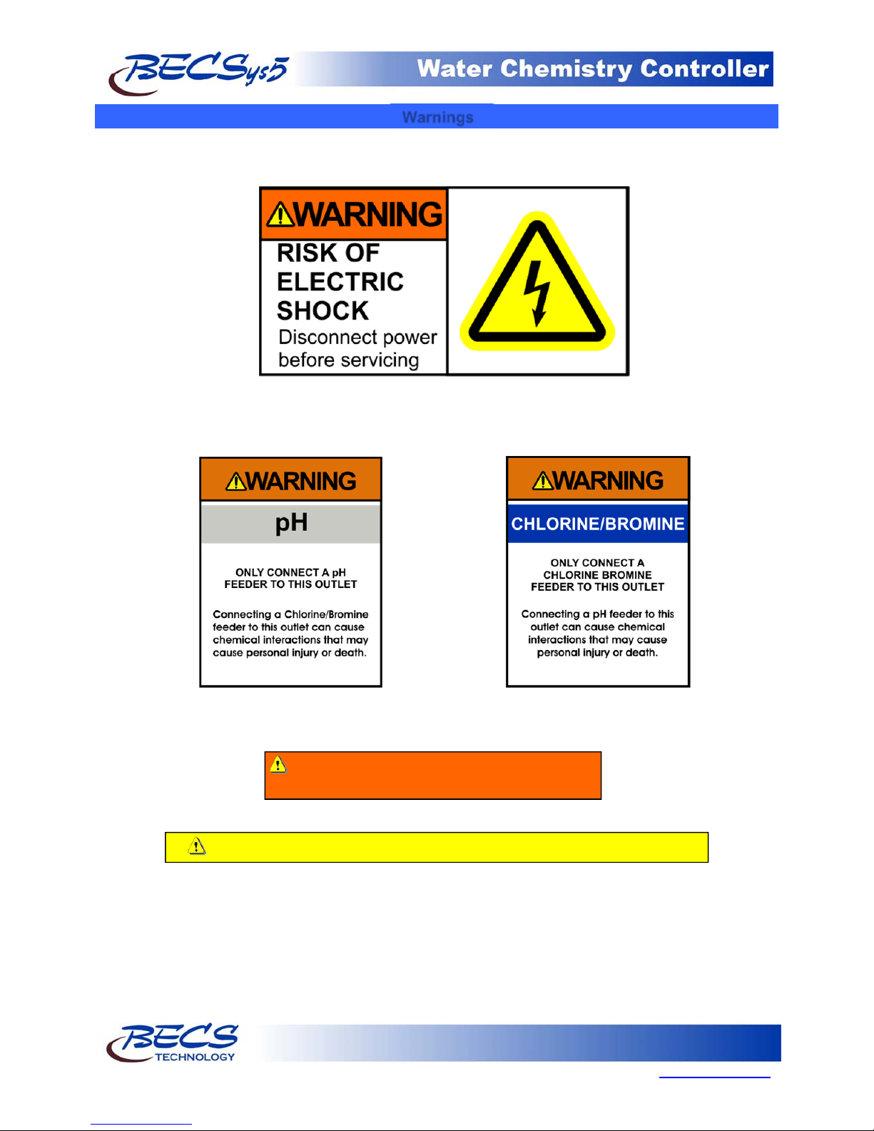
Warnings
Pay particular attention to the following warnings encountered while utilizing your
BECSys5 Water Chemistry Controller:
Rev: L13
Warning: Various other warning boxes may be
found throughout the manual text.
Caution: Various caution boxes may be found throughout the manual text.
Page 1
9487 Dielman Rock Island Ind Dr, St. Louis, MO 63132 www.becs.com
Operation and Maintenance Manual
g
A
A
l
V
(
(12A
l
Rev: L13
General Guidelines
Proper installation and use of the BECSys controller depends on the specific needs of the application. Read the manual
completely before starting the installation and ensure all guidelines and recommendations are followed. All components
should be mounted and the flow cell plumbing installed and pressure tested before wiring the controller. Ensure
compliance with all applicable plumbing and electrical codes during the installation as well.
Caution: The BECSys controller should be sealed while under operation. All IO, power cables, and unused
ports must be sealed using hardware rated NEMA4 or better. Damage to the controller caused by improper
Caution: The BECSys controller should not be installed where it is accessible to the public.
sealing of the enclosure is not covered under warranty.
Firmware Version
This manual was written for firmware v1.54. If you received newer firmware but did not receive a copy of the manual
covering that version of firmware, please contact your distributor.
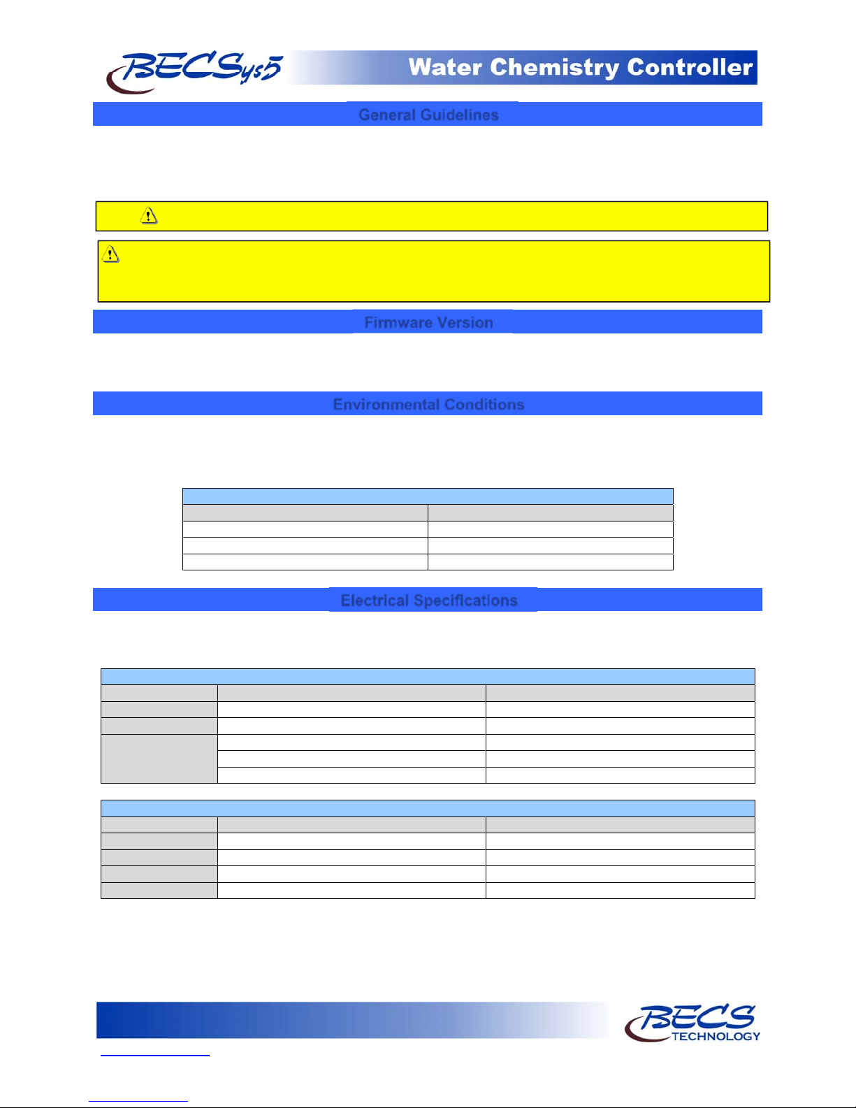
Environmental Conditions
The BECSys5 is housed in a NEMA 4X (IP65) enclosure. It should not be used in explosive environments. The
BECSys5 should be mounted so that adequate ventilation is provided around the enclosure, preventing general
environmental specifications from being exceeded (see table below).
Environmental Specifications
Specification Ratin
Storage Temperature -40 to 85 Deg C
mbient Operating Temperature -18 to 50 Deg C
mbient Humidity 95% non condensing maximum humidity
Electrical Specifications
The BECSys5 may be ordered in either an 115VAC model or a 230VAC model. Following are the electrical
specifications for each model:
Controller Ratings
115VAC Model 230VAC Mode
oltage: 115VAC 60Hz 230VAC 50Hz
Phase: Single Single
Current: 12.25 Amps Full Load 12.125 Amps Full Load
(¼ Amp – Controller)
(12 Amps – Relay Outputs: 3A X 4)
Relay Output Ratings
115VAC Model 230VAC Mode
Relay 1 (K1) 250VAC (max) – 3 Amps 250VAC (max) –3Amps
Relay 2 (K2) 250VAC (max) – 3 Amps 250VAC (max) –3Amps
Relay 3 (K3) 250VAC (max) – 3 Amps 250VAC (max) –3Amps
Relay 4 (K4) 250VAC (max) – 3 Amps 250VAC (max) –3Amps
⅛ Amp –Controller)
mps –Relay Outputs: 3A X 4)
Page 2
www.becs.com 9487 Dielman Rock Island Ind Dr, St. Louis, MO 63132
Operation and Maintenance Manual
V
V
T
A
T
V
V
T
–
–
Rev: L13
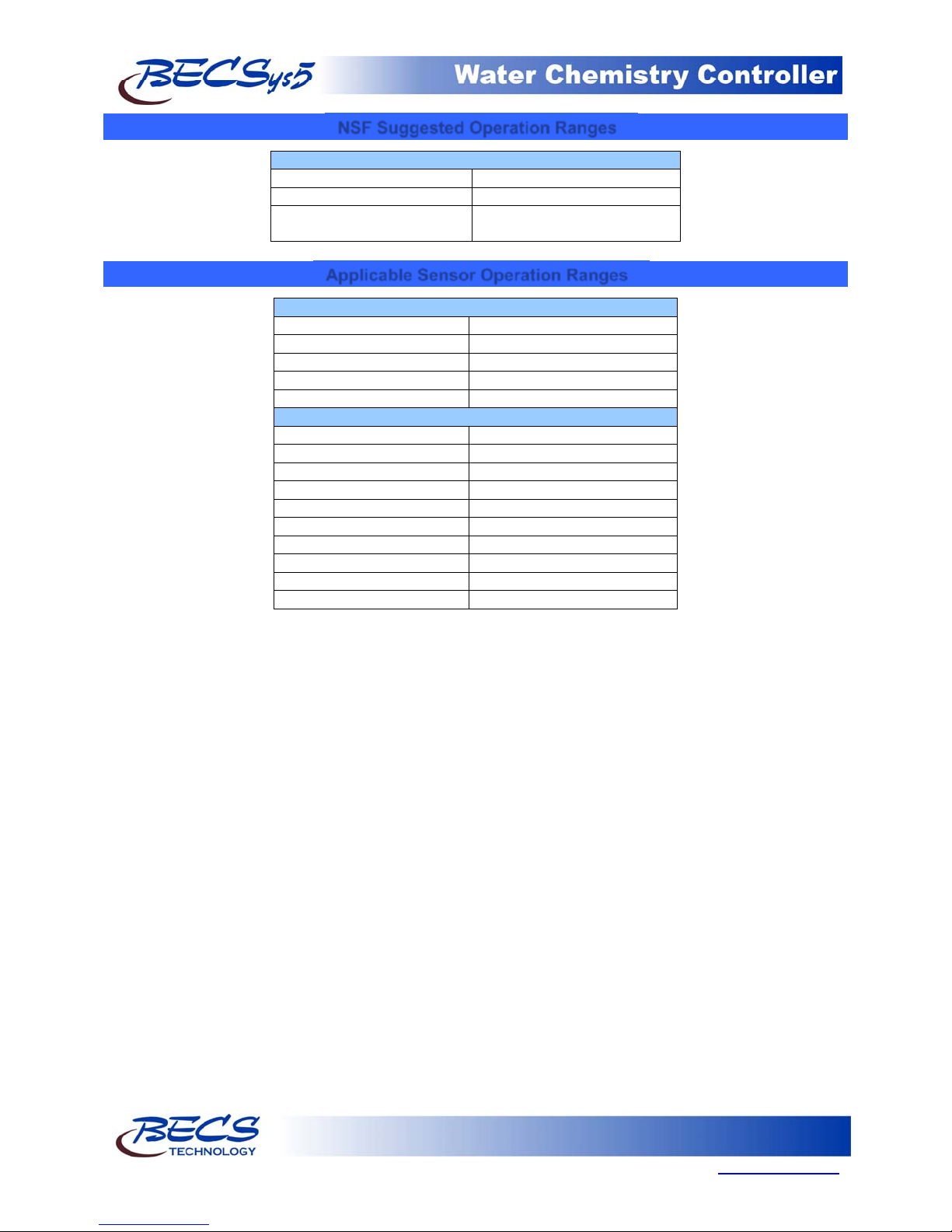
NSF Suggested Operation Ranges
ORP 650mV to 850m
pH 6.8 to 8.2
Free Available 0 to 10 ppm
Chlorine
Applicable Sensor Operation Ranges
Standard Sensors
pH 0.0 to 14.0 pH
ORP -1500mV to 1500m
emperature 32°F to 212°F (0°C to 100°C)
Reed Flow Switch Switch Point (On): 2.0 gpm
Rotary Flow Switch Switch Point (On): 1.5 gpm
Optional Sensors
mperometric ppm 0 ppm to 20 ppm
otal Chlorine 0 ppm to 20 ppm
Pressure Transducer 0 to 100 PSI
acuum Transducer -14.7 to 85 PSI
acuum Swichgage 0 –30 in. HG
Pressure Swichgage 0 –50 PSI
Differential Swichgage 0 –50 PSI
Conductivity Sensor 0 –20,000 micromho
urbidimeter 0
Flowmeter 0
20.0 NTU
655.35 Kgpm
Page 3
9487 Dielman Rock Island Ind Dr, St. Louis, MO 63132 www.becs.com
Operation and Maintenance Manual
Section A: Programming the Controller
Rev: L13
A – 1: Adjusting the Display Contrast
You can adjust the display contrast by holding down
either the up or down arrow keys for two seconds,
then after the controller beeps three times, use the
up and down keys to adjust the contrast.
A – 2: Security Settings
A – 2.1: Access Codes and levels
To view what access level you were given, press
the lock screen button while in any menu.
The Main Menu will also display who is logged on
along with the version of firmware.
You do not need to set all the access codes for
each level if you do not wish to. Also, a disabled
access code is not equivalent to 000, so entering
000 when it prompts for an access code will only
work if you have specifically assigned an access
code to be 000.
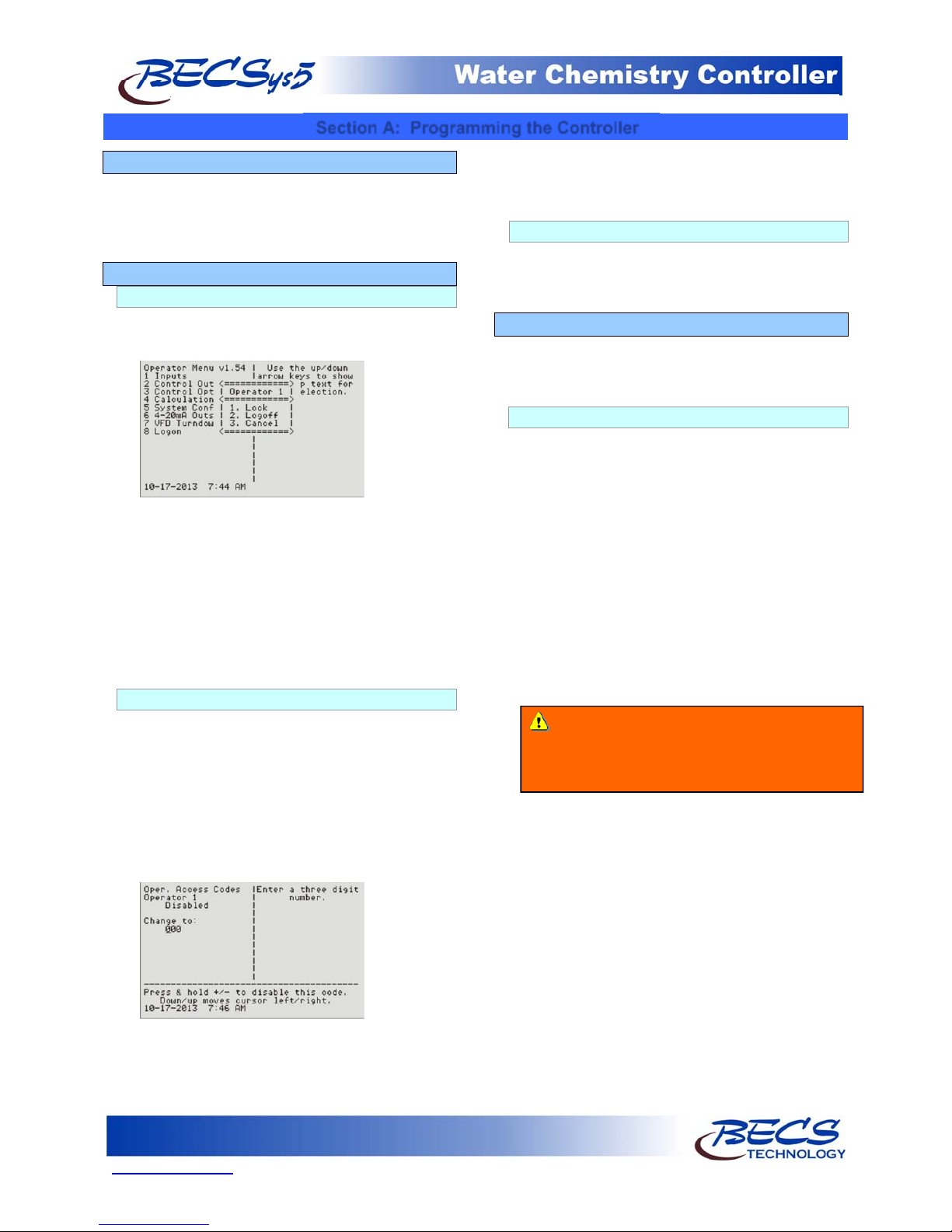
A – 2.2: Setting Access Codes
To set an access code, press the menu button,
then:
Select System Config
Choose User Setup
Then select the access level you want to set an
access code for.
To set Operator 1's access code, you would select
Oper. Access Codes, then select Operator 1.
Pressing and holding the +/- button disables the
access code, while pressing enter will enable and
set the access code to the value on the screen.
Operators may only change their own access code.
Managers may change their access code and any of
the Operators.
A – 2.3: Controller Options
Depending on how a particular controller is
configured, not all of the options listed in this
manual may be available.
A – 3: Navigating the menus
The controller's menus incorporate built in help text
to aid in understanding the function of each
parameter, item, and option.
A – 3.1: Common status messages
The very bottom line of the display contains the
time and date on the left while the right is reserved
for a number of status messages; the most
common are as follows:
"Busy..." - Indicates the controller is busy doing
something critical and it cannot stop until it
finishes. Until this message disappears, the
controller will not respond to your key presses
(although it does record them any will process
them when done). Normally this message is only
seen briefly after changing a setting, but it is also
used for lengthier operations such as factory
defaults and in the extremely rare case where the
internal diagnostics detect a memory problem and
attempts to correct it.
Warning: Interrupting the controller by
turning the power off while it displays the busy
message could result in the complete loss of all
"(1 of 2) (More )" - and the like indicate there
are more options for you to choose from than the
controller could show at one time. Press the right
arrow key (Next) to view them. The left number
indicates the current page, while the right number
indicates the total number of pages.
"Bad Value, Retry..." - Accompanied by an error
beep, this indicates the value you just entered was
not within the allowable range of values and was
not stored.
of its settings.
Page 4
www.becs.com 9487 Dielman Rock Island Ind Dr, St. Louis, MO 63132
Operation and Maintenance Manual
A – 3.2: The Menu Screens
Most of the features of the controller are
configured via the Menu button's menus. The
menu screens can be broken up into two types:
entry screens and lists.
A – 3.2.1: Entry Screens
An entry screen is used to enter a value using
the keypad.
Rev: L13
A – 3.2.2: List Screens
The list screens are mainly composed of lists of
menu items that you can choose from by either
pressing an item's number or by using the up
and down arrow keys to select it (indicated by
the arrow) and then pressing enter to choose it.
Using the up and down arrow keys also allows
you to view each item's help text. And if the
item leads to an entry screen or a list screen that
sets a setting (see below), the current value is
displayed in the lower right side.
Lists can also be used to change a setting:
The current value is usually displayed at the top
while the cursor will be positioned under the
current digit or character of the value you are
entering in. The up and down arrows allow you
to move the cursor right or left so you do not
have to retype the existing digits if you only wish
to change one.
Most numerical values will display the minimum
and maximum values you can enter in at the
bottom of the display in the format "< ### to
###>". These ranges many times will be
dependant on other values you have set, such as
alarm points or set points, while others are
simply fixed to stay within a reasonable range.
Entering a value that is not within the acceptable
range will result in an error beep and the
message "Bad Value, Retry..." being displayed in
the status area.
For some values, certain keys may take on
special functions that are explained in the lower
lines of the screen. The Down/up message in
the example above is one of them.
When a list is used this way, it will display the
current setting followed by the words "Change
to:". Because it is a list, you can select an item
with the up/down buttons to see help
information about that particular selection.
There are a few list screens that use the entire
width of the display for displaying values
associated with each item and therefore do
not have help. See Section C: Using the
Quick Set Face Panel Keys for examples of
these types of screens.
Page 5
9487 Dielman Rock Island Ind Dr, St. Louis, MO 63132 www.becs.com
Operation and Maintenance Manual
A – 3.3: The Lock Screen Key
When not in a menu (i.e. viewing the normal
display), pressing the lock screen key will prevent
the controller from paging the screen to show
more inputs, alarms, and other status information.
See Section B: The Normal Display for more info
about using the lock screen key in the normal
display.
While within any menu, if the user does not press
a key within sixty seconds of the last key press, the
current user is logged out and the screen is
returned to the normal display. To prevent the
controller from timing out, you may lock the
screen.
While within a menu, pressing the Lock Screen key
will bring up a popup menu:
The first option on the popup will be either to
lock or unlock the screen depending on the
current lock state. While the screen is locked, key
presses normally are ignored. However, in some
instances certain keys are given special functions
while the screen is locked, such as using the up
and down arrows to scroll the help text if all of the
help text cannot be displayed at once.
You can also lock/unlock the screen without
bringing up the popup menu by holding down
the lock button for one second. The
controller will acknowledge this action with a
triple beep and the yellow Lock Screen light
will turn on.
The Lock button popup menu also identifies who
is currently logged on, and provides an option for
the user to log off. You can also select cancel if
you pressed the lock button in error.
Rev: L13
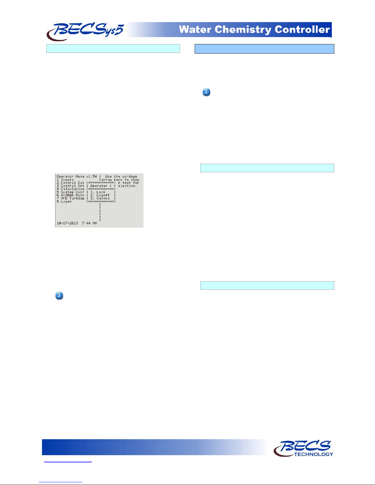
A – 4: Inputs
To enter the program menu, press the Menu button
on the front face panel of your controller. This will
allow the viewing of the Main Menu where the
programming options are displayed.
The Cl inputs, Cl Inventory Input, Chlorine
Control, and Chlorine booster control are all
displayed as either Chlorine and Cl or Bromine
and Br depending on the chemical selected in the
Cl feed menu. This manual is written using the
Chlorine setting. If you select Bromine as the
sanitizing chemical, the controller will display
Bromine and Br instead of Chlorine and Cl, but
the menus and functions are otherwise exactly the
same as shown.
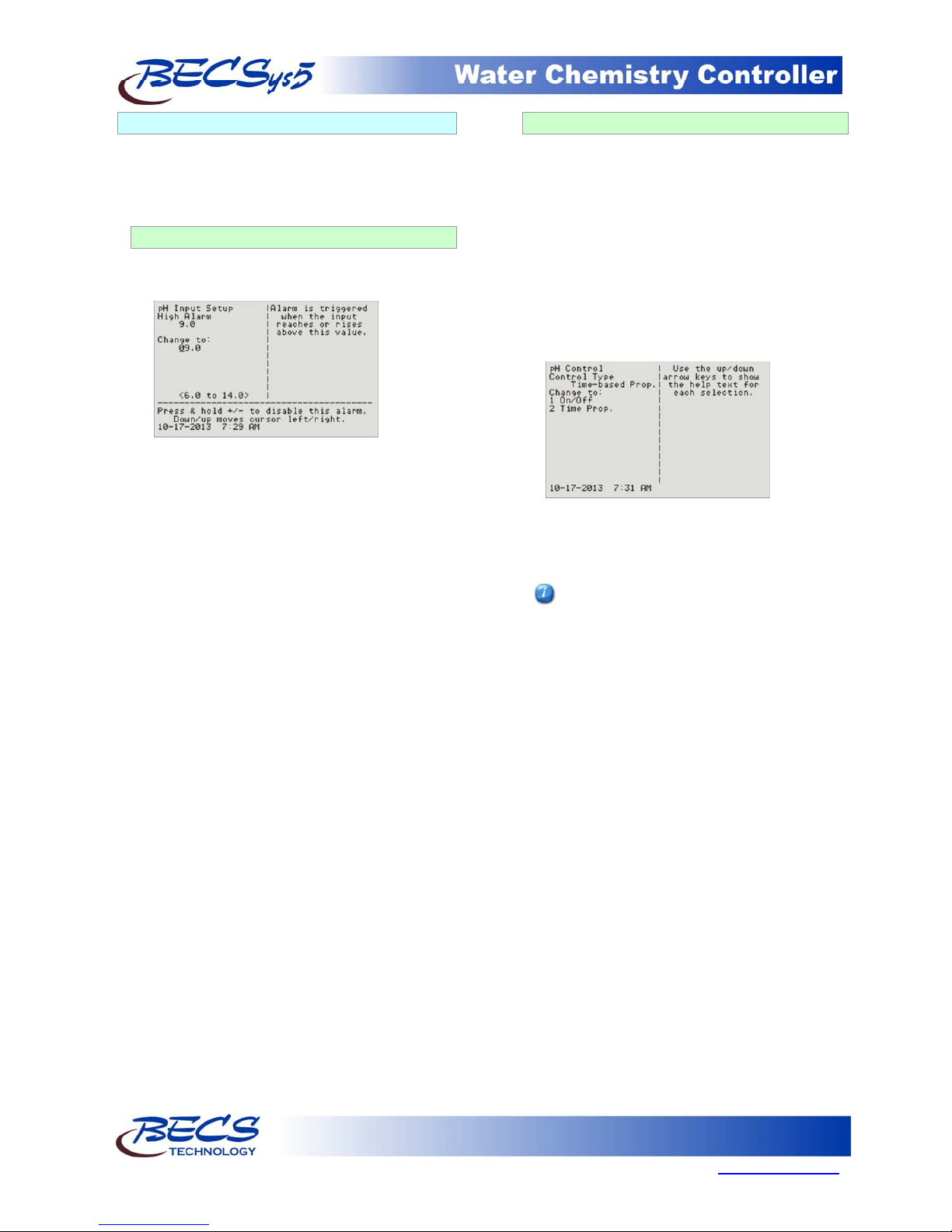
A – 4.1: pH Setup
If your controller is configured to monitor pH,
you will have the following options:
High Alarm (Op): The high alarm will activate
when the pH reaches or rises above this setting.
You may disable this alarm by holding down the
+/- key for 1 second.
Low Alarm (Op): The low alarm will activate
when the pH reaches or falls below this setting.
You may disable this alarm by holding down the
+/- key for 1 second.
Alarm Hysteresis (Mgr): This value sets the
amount that the pH reading has to rise above the
high alarm or fall below the low alarm before the
alarm will shut off.
A – 4.2: ORP Setup
If your controller is configured to monitor ORP,
you will have the following options:
High Alarm (Op): The high alarm will activate
when the ORP reaches or rises above this setting.
You may disable this alarm by holding down the
+/- key for 1 second.
Low Alarm (Op): The low alarm will activate
when the ORP reaches or falls below this setting.
You may disable this alarm by holding down the
+/- key for 1 second.
Alarm Hysteresis (Mgr): This value sets the
amount that the ORP reading has to rise above the
high alarm or fall below the low alarm before the
alarm will shut off.
Page 6
www.becs.com 9487 Dielman Rock Island Ind Dr, St. Louis, MO 63132
Operation and Maintenance Manual
A – 4.3: Cl Inputs Setup
A – 4.3.1: Free Cl Setup
If your controller is configured to monitor Free
Cl, it may be either calculated or a probe may be
attached.
Caution: Amperometric chlorine sensors
require the use of a temperature sensor and
a properly calibrated pH sensor. Refer to
the instruction pamphlet included with the
sensor at the time of installation.
A – 4.3.1.1: Input Source: Calculated
High Alarm (Op): The high alarm will
activate when the free Cl reaches or rises
above this setting. You may disable this
alarm by holding down the +/- key for 1
second.
Low Alarm (Op): The low alarm will
activate when the free Cl reaches or falls
below this setting. You may disable this
alarm by holding down the +/- key for 1
second.
Alarm Hysteresis (Mgr): This value sets
the amount that the Cl input readings have
to rise above their high alarm or fall below
their low alarm before the alarm will shut
off.
A – 4.3.1.2: Input Source: Probe
High Alarm (Op): The high alarm will
activate when the free Cl reaches or rises
above this setting. You may disable this
alarm by holding down the +/- key for 1
second.
Low Alarm (Op): The low alarm will
activate when the free Cl reaches or falls
below this setting. You may disable this
alarm by holding down the +/- key for 1
second.
Alarm Hysteresis (Mgr): This value sets
the amount that the Cl input readings have
to rise above their high alarm or fall below
their low alarm before the alarm will shut
off. Note this value is used for free, total,
and combined Cl alarms.
Calibrate (Op): This selection allows you
to do a single point calibration of free Cl,
enter the reading from you test kit, and press
enter. The value entered must be 0.5 ppm
or greater.
Reset Calibration (Op): Resets the
calibration to the original factory setting.
A – 4.3.2: Total Cl Setup
If your controller is configured to monitor Total
Cl, you will have the following options:
High Alarm (Op): The high alarm will activate
when the total Cl reaches or rises above this
setting. You may disable this alarm by holding
down the +/- key for 1 second.
Low Alarm (Op): The low alarm will activate
when the total Cl reaches or falls below this
setting. You may disable this alarm by holding
down the +/- key for 1 second.
Alarm Hysteresis (Mgr): This value sets the
amount that the Cl input readings have to rise
above their high alarm or fall below their low
alarm before the alarm will shut off. Note this
value is used for free, total, and combined Cl
alarms.
A – 4.3.3: Combined Cl
If your controller is configured to monitor
Combined Cl, you will have the following
options:
High Alarm (Op): The high alarm will
activate when the combined Cl reaches or rises
above this setting. You may disable this alarm
by holding down the +/- key for 1 second.
Alarm Hysteresis (Mgr): This value sets the
amount that the Cl input readings have to rise
above their high alarm or fall below their low
alarm before the alarm will shut off. Note this
value is used for free, total, and combined Cl
alarms.
A – 4.4: Temperature Setup
If your controller is configured to monitor
temperature, you will have the following options:
High Alarm (Op): The high alarm will activate
when the temperature reaches or rises above this
setting. You may disable this alarm by holding
down the +/- key for 1 second.
Low Alarm (Op): The low alarm will activate
when the temperature reaches or falls below this
setting. You may disable this alarm by holding
down the +/- key for 1 second.
Alarm Hysteresis (Mgr): This value sets the
amount that the temperature reading has to rise
above the high alarm or fall below the low alarm
before the alarm will shut off.
Rev: L13
Page 7
9487 Dielman Rock Island Ind Dr, St. Louis, MO 63132 www.becs.com
Operation and Maintenance Manual
A – 4.5: Conductivity/TDS Setup
If your controller is configured to monitor
Conductivity/TDS, you will have the following
options:
High Alarm (Op): The high alarm will activate
when the input reaches or rises above this setting.
You may disable this alarm by holding down the
+/- key for 1 second.
Low Alarm (Op): The low alarm will activate
when the input reaches or falls below this setting.
You may disable this alarm by holding down the
+/- key for 1 second.
Alarm Hysteresis (Mgr): This value sets the
amount that the Conductivity/TDS reading has to
rise above the high alarm or fall below the low
alarm before the alarm will shut off.
A – 4.6: Flow Rate Setup
If your controller is configured to monitor Flow
Rate, you will have the following options:
Low Alarm (Op): The low alarm will activate
when the flow rate reaches or falls below this
setting. You may disable this alarm by holding
down the +/- key for 1 second.
Alarm Hysteresis (Mgr): This value sets the
reading that the flow rate must rise above the low
alarm before the alarm will shut off.
A – 4.7: pH & Chlorine Inventory Setups
If your controller is configured to monitor
chemical inventories, a sensor may be used or a
contact switch. If a sensor is used, you will have
the following options:
Low Alarm (Op): This value sets at what level or
weight the inventory low alarm will be activated.
You may disable this alarm by holding down the
+/- key for 1 second.
Alarm Hysteresis (Mgr): This value sets at what
level the inventory level or weight has to rise
above the low level or weight alarm setting before
the alarm will shut off.
A – 4.8: Turbidity
If your controller is configured to monitor
Turbidity, you will have the following options:
High Alarm (Op): The high alarm will activate
when the input reaches or rises above this setting.
You may disable this alarm by holding down the
+/- key for 1 second.
Alarm Hysteresis (Mgr): This value sets the
level that the turbidity reading has to rise above
the high alarm setting before the alarm will shut
off.
Rev: L13
A – 4.9: Surge Pit Level
If your controller is configured to monitor the
Surge Pit Level, a sensor may be used or a contact
switch. If a sensor is used, you will have the
following options:
High Alarm (Op): The high alarm will
activate when the input reaches or rises above
this setting. You may disable this alarm by
holding down the +/- key for 1 second.
Low Alarm (Op): The low alarm will activate
when the input reaches or falls below this
setting. You may disable this alarm by holding
down the +/- key for 1 second.
Alarm Hysteresis (Mgr): This value sets the
amount that the surge pit level has to rise above
the high alarm or fall below the low alarm
before the alarm will shut off.
A – 4.10: Pressure & Vacuum Setup
A – 4.10.1: Filter Influent Pressure
If your controller is configured to monitor the
Filter Influent Pressure, either a PSI transducer,
Vacuum transducer, or a gauge may be used. If
a transducer is used, you will have the following
options:
High Alarm (Op): The high alarm will activate
when the pressure reaches or rises above this
setting. You may disable this alarm by holding
down the +/- key for 1 second.
Low Alarm (Op): The low alarm will activate
when the pressure falls below this setting. You
may disable this alarm by holding down the +/key for 1 second.
Alarm Hysteresis: (Mgr) This value sets the
amount that the pressure reading has to rise
above the high alarm or fall below the low
alarm before the alarm will shut off.
Display Input (Op): This option
enables/disables displaying the influent pressure
on the normal display.
A – 4.10.2: Filter Effluent Pressure
If your controller is configured to monitor the
Filter Effluent Pressure, either a PSI transducer,
or a pressure gauge may be used. If a transducer
is used, you will have the following options:
High Alarm (Op): The high alarm will
activate when the pressure reaches or rises
above this setting. You may disable this alarm
by holding down the +/- key for 1 second.
Low Alarm (Op): The low alarm will activate
when the pressure reaches or falls below this
setting. You may disable this alarm by holding
down the +/- key for 1 second.
Page 8
www.becs.com 9487 Dielman Rock Island Ind Dr, St. Louis, MO 63132
 Loading...