


BECSys3
Operation and Maintenance Manual

Operation and Maintenance Manual
Rev: K12
TTAABBLLEE OOFF CCOONNTTEENNTTSS
Warnings ............................................................................. 1
General Guidelines ............................................................. 2
Firmware Version ............................................................... 2
Environmental Conditions .................................................. 2
Electrical Specifications ...................................................... 2
NSF Suggested Operation Ranges ...................................... 3
Applicable Sensor Operation Ranges ................................. 3
Section A: Programming the Controller ............................ 4
A – 1: Controller Options .............................................. 4
A – 2: The Program Menu ............................................. 4
A – 2.1: Entering the Program Menu ......................... 4
A – 2.2: Selecting Language ...................................... 4
A – 2.3: pH High Alarm Point ................................... 4
A – 2.4: pH Low Alarm Point .................................... 4
A – 2.5: ORP High Alarm Point ................................ 4
A – 2.6: ORP Low Alarm Point ................................. 5
A – 2.7: Temperature High Alarm Point .................... 5
A – 2.8: Temperature Low Alarm Point .................... 5
A – 2.9: ORP/ppm Set point ...................................... 5
A – 2.10: ppm High Alarm ........................................ 5
A – 2.11: ppm Low Alarm ......................................... 5
A – 2.12: Exiting the Menu ........................................ 5
Section B: Normal Operation ............................................. 6
B – 1: Set points ............................................................. 6
B – 1.1: Displaying the Set points .............................. 6
B – 1.2: Modifying the Set points .............................. 6
B – 1.2.1: pH Set Point .......................................... 6
B – 1.2.2: Chlorine Set Point ................................. 6
B – 1.2.2.1: ORP Control ................................... 6
B – 1.2.2.2: ppm Control (Calculated) ............... 6
B – 1.2.2.3: ppm Control (Probe) ....................... 6
B – 1.2.3: Booster Trigger Point ............................ 6
B – 1.2.4: Booster End Point .................................. 6
B – 2: Single Point Calibration ...................................... 7
B – 2.1: Single Point Calibration - pH ....................... 7
B – 2.2: Single Point Calibration - Temp ................... 7
B – 2.3: Single Point Calibration – ppm .................... 7
B – 2.3.1: Calculated ppm ...................................... 7
B – 2.3.2: ppm Probe ............................................. 7
B – 2.4: Probe Error ................................................... 7
B – 3: Alarms ................................................................. 7
B – 3.1: pH High/Low alarms .................................... 7
B – 3.2: ORP High/Low alarms ................................. 7
B – 3.3: ppm High/Low alarms .................................. 7
B – 3.4: Temperature High/Low alarms .................... 7
B – 3.5: No Flow Alarm............................................. 8
B – 3.6: Flow Restored Delay .................................... 8
B – 3.7: Cl/Br Lockout ............................................... 8
B – 3.8: pH Failsafe ................................................... 8
B – 3.9: Cl/Br Failsafe ............................................... 8
B – 3.10: Booster FAILSAFE .................................... 8
B – 4: Resetting a Failsafe Alarm .................................. 8
Section C: Using the BECSysRCM3 ................................. 9
C – 1: Monitoring a Controller ....................................... 9
C – 2: Downloading Data Logs ...................................... 9
C – 2.1: Using a Flash Drive .................................... 10
C – 2.1.1: Importing Data Logs ............................ 11
C – 3: Viewing Data Logs ............................................ 11
Section D: Troubleshooting .............................................. 12
D – 1: BECSys3 ........................................................... 12
D – 1.1: Probe Error ................................................. 12
D – 2: BECSysRCM3................................................... 12
D – 2.1: Problems Using A Flash Drive ................... 12
D – 2.2: Text Message Call-Out Test ....................... 12
Section E: Maintenance .................................................... 13
E – 1: Potentiometric Sensors (pH and ORP) ............... 13
E – 1.1: Electrode Cleaning: ..................................... 13
E – 1.2: Long-Term Storage: .................................... 13
E – 2: CCS140 Free Chlorine Sensor ........................... 13
E – 2.1: Cleaning ...................................................... 13
E – 2.2: Long-Term Storage ..................................... 13
E – 2.3: Filling electrolyte ........................................ 13
Section F: Feed Charts ..................................................... 14
F – 1: Spa Feed Charts ................................................. 14
F – 2: Pool Feed Charts ................................................ 15
Section G: Installation Diagrams ...................................... 16
G – 1: Pressure Filter Installation ................................. 16
G – 2: Vacuum Filter Installation ................................. 16
Section H: Replacement Parts .......................................... 17
Section I: Warranty .......................................................... 18
9487 Dielman Rock Island Ind Dr, St. Louis, MO 63132 www.becs.com

Operation and Maintenance Manual
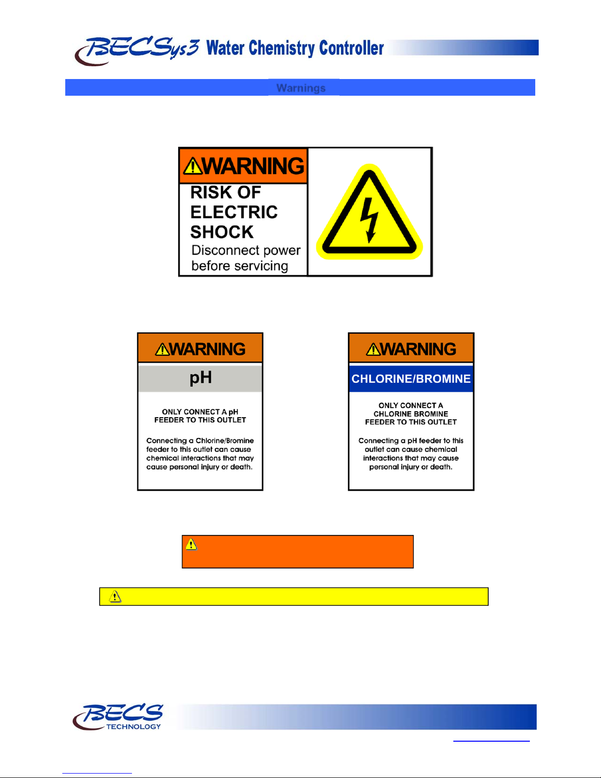
Warnings
Pay particular attention to the following warnings encountered in the pages of the
BECSys3 Operation and Maintenance Manual:
Rev: K12
Warning: Various other warning boxes may be
found throughout the manual text.
Caution: Various other caution boxes may be found throughout the manual text.
Page 1
9487 Dielman Rock Island Ind Dr, St. Louis, MO 63132 www.becs.com
Operation and Maintenance Manual
g
A
A
l
V
(
(
l
Rev: K12
General Guidelines
Proper installation and use of the BECSys controller depends on the specific needs of the application. Read the manual
completely before starting the installation and ensure all guidelines and recommendations are followed. All components
should be mounted and the flow cell plumbing installed and pressure tested before wiring the controller. Ensure
compliance with all applicable plumbing and electrical codes during the installation as well.
Caution: The BECSys controller should be sealed while under operation. All IO, power cables, and unused
ports must be sealed using hardware rated NEMA4 or better. Damage to the controller caused by improper
Caution: The BECSys controller should not be installed where it is accessible to the public.
sealing of the enclosure is not covered under warranty.
Firmware Version
This manual was written for firmware v2.08 & v2.09. If you received newer firmware but did not receive a copy of the
manual covering that version of firmware, please contact your distributor.
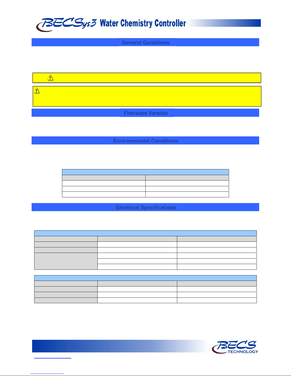
Environmental Conditions
The BECSys3 is housed in a NEMA 4X (IP65) enclosure. It should not be used in explosive environments. The
BECSys3 should be mounted so that adequate ventilation is provided around the enclosure, preventing general
environmental specifications from being exceeded (see table below).
Environmental Specifications
Specification Ratin
Storage Temperature -30 to 60 Deg C
mbient Operating Temperature -18 to 40 Deg C
mbient Humidity 95% non condensing maximum humidity
Electrical Specifications
The BECSys3 may be ordered in either an 115VAC model or a 230VAC model. Following are the electrical
specifications for each model:
Controller Ratings
115VAC Mode
oltage: 115VAC 60Hz 230VAC 50Hz
Phase: Single Single
Current: 9.25 Amps Full Load 4.625 Amps Full Load
(¼ Amp –Controller)
(9 Amps –Relay Outputs, 3A X 3)
Relay Output Ratings
115VAC Mode
Relay 1 (K1) 115VAC (max) –3 Amps 250VAC (max) – 1.5 Amps
Relay 2 (K2) 115VAC (max) –3 Amps 250VAC (max) – 1.5 Amps
Relay 3 (K3) 115VAC (max) –3 Amps 250VAC (max) – 1.5 Amps
230VAC Model
⅛ Amp –Controller)
4.5Amps –Relay Outputs, 1.5A X 3)
230VAC Model
Page 2
www.becs.com 9487 Dielman Rock Island Ind Dr, St. Louis, MO 63132
Operation and Maintenance Manual
V
T
V
A
Rev: K12
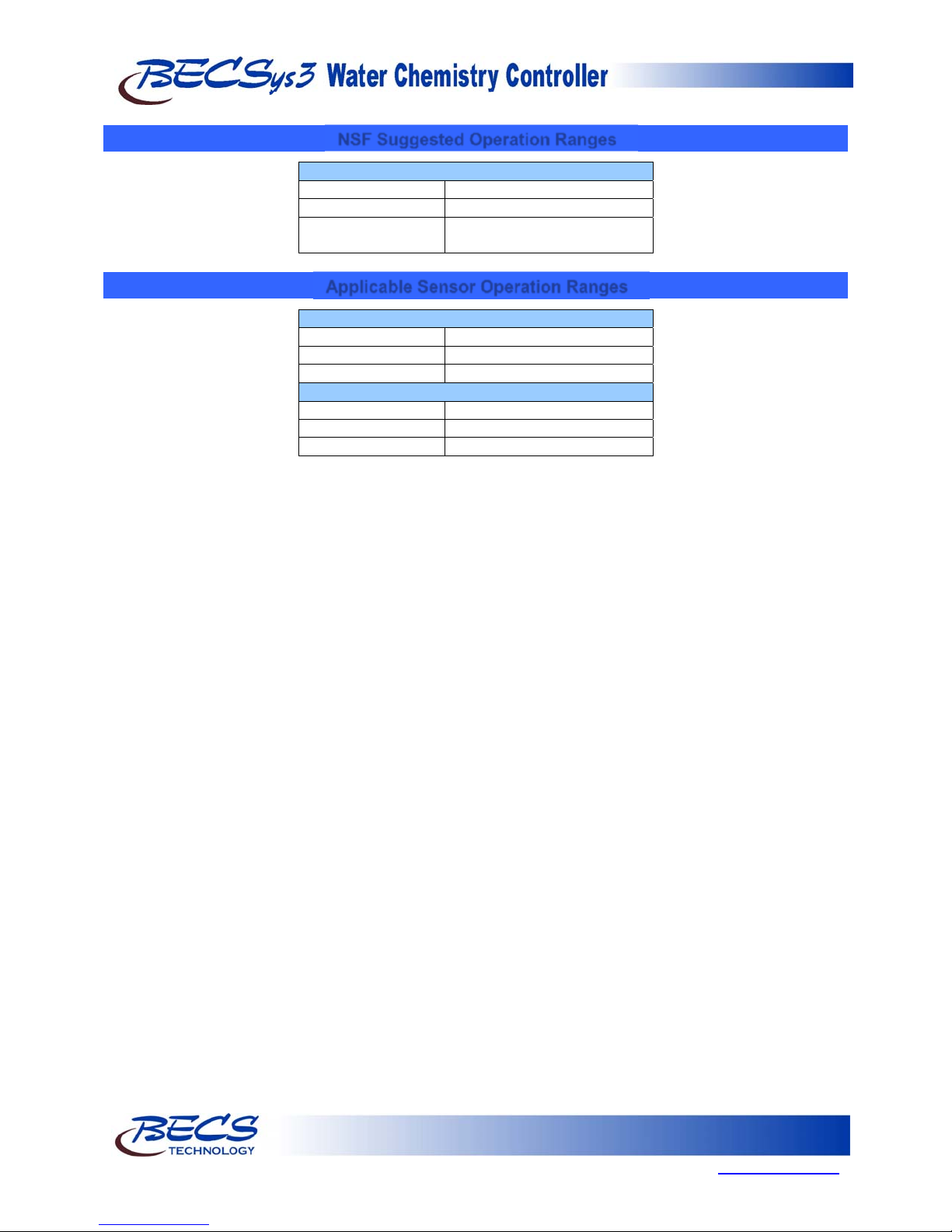
NSF Suggested Operation Ranges
ORP 650mV to 850m
pH 6.8 to 8.2
Free Available 0 to 10 ppm
Chlorine
Applicable Sensor Operation Ranges
Standard Sensors
pH 0.0 to 14.0 pH
Reed Flow Switch Switch Point (On): 2.0 gpm
Rotary Flow Switch Switch Point (On): 1.5 gpm
Optional Sensors
emperature 32°F to 212°F (0°C to 100°C)
ORP -1500mV to 1500m
mperometric ppm 0 ppm to 20 ppm
Page 3
9487 Dielman Rock Island Ind Dr, St. Louis, MO 63132 www.becs.com
 Loading...