

Page 1
Operator’s Manual
TECHNOLOGY
9487 Dielman Rock Island Industrial Dr. St. Louis, MO 63132 Tel:(314) 567-0088
Page 2
Operator’s Manual
TABLE OF CONTENTS
Section A: Programming the Controller......................................................................................................................................... 1
A - 1: Entering the Program Menu............................................................................................................................................. 1
A - 1.1: Selecting Language...................................................................................................................................................... 1
A - 1.2: Setting the pH High Alarm Point............................................................................................................................. 1
A - 1.3: Setting the pH Low Alarm Point.............................................................................................................................. 1
A - 1.4: Setting the ORP High Alarm Point.......................................................................................................................... 1
A - 1.5: Setting the ORP Low Alarm Point........................................................................................................................... 1
A - 1.6: ORP/ppm..................................................................................................................................................................... 1
A - 1.7: Exiting the Menu ........................................................................................................................................................ 1
Section B: Normal Operation .......................................................................................................................................................... 2
B - 1: Displaying the Set Points................................................................................................................................................... 2
B - 2: Modifying the Set Points ................................................................................................................................................... 2
B - 2.1: Modifying the pH Set Point....................................................................................................................................... 2
B - 2.2: Modifying the ORP Set Point.................................................................................................................................... 2
B - 2.3: Modifying the ppm Set point..................................................................................................................................... 2
B - 2.4: Modifying the Booster Trigger Point ....................................................................................................................... 2
B - 2.5: Modifying the Booster End Point............................................................................................................................. 2
B - 3: Single Point Calibration ..................................................................................................................................................... 2
B - 3.1: Single Point Calibration - pH .................................................................................................................................... 2
B - 3.2: Single Point Calibration - ppm.................................................................................................................................. 2
B - 4: Alarms .................................................................................................................................................................................. 3
B - 4.1: pH High/Low alarms.................................................................................................................................................. 3
B - 4.2: ORP High/Low alarms............................................................................................................................................... 3
B - 4.3: No Flow alarm.............................................................................................................................................................. 3
B - 4.4: (x) min Feed Delay....................................................................................................................................................... 3
B - 4.5: Cl/Br Lockout.............................................................................................................................................................. 3
B - 4.6: pH FAILSAFE ALM................................................................................................................................................... 3
B - 4.7: Cl/Br FAILSAFE ........................................................................................................................................................ 3
B - 4.8: Booster FAILSAFE..................................................................................................................................................... 3
B - 5: Resetting a Failsafe Alarm................................................................................................................................................. 3
Section C: Maintenance...................................................................................................................................................................... 4
C - 1: Potentiometric Sensors (pH and ORP) ........................................................................................................................... 4
C - 1.1: Electrode Cleaning:..................................................................................................................................................... 4
C - 1.2: Long-Term Storage:.................................................................................................................................................... 4
Section D: Feed Charts ...................................................................................................................................................................... 5
D - 1: Spa Feed Charts................................................................................................................................................................... 5
D - 2: Pool Feed Charts................................................................................................................................................................. 6
Section E: Installation Diagrams....................................................................................................................................................... 7
E - 1: Pressure Filter Installation.................................................................................................................................................. 7
E - 2: Vacuum Filter Installation.................................................................................................................................................. 7
Section F: Warranty ............................................................................................................................................................................ 8
FIRMWARE VERSION NOTE
This manual was written for firmware v1.02. If you received newer firmware but did not receive an electronic copy of
the manual covering that version of firmware, please contact your distributor.
TECHNOLOGY
9487 Dielman Rock Island Industrial Dr. St. Louis, MO 63132 Tel:(314) 567-0088
Page 3
Operator’s Manual
Section A: Programming the Controller
A - 1: Entering the Program Menu
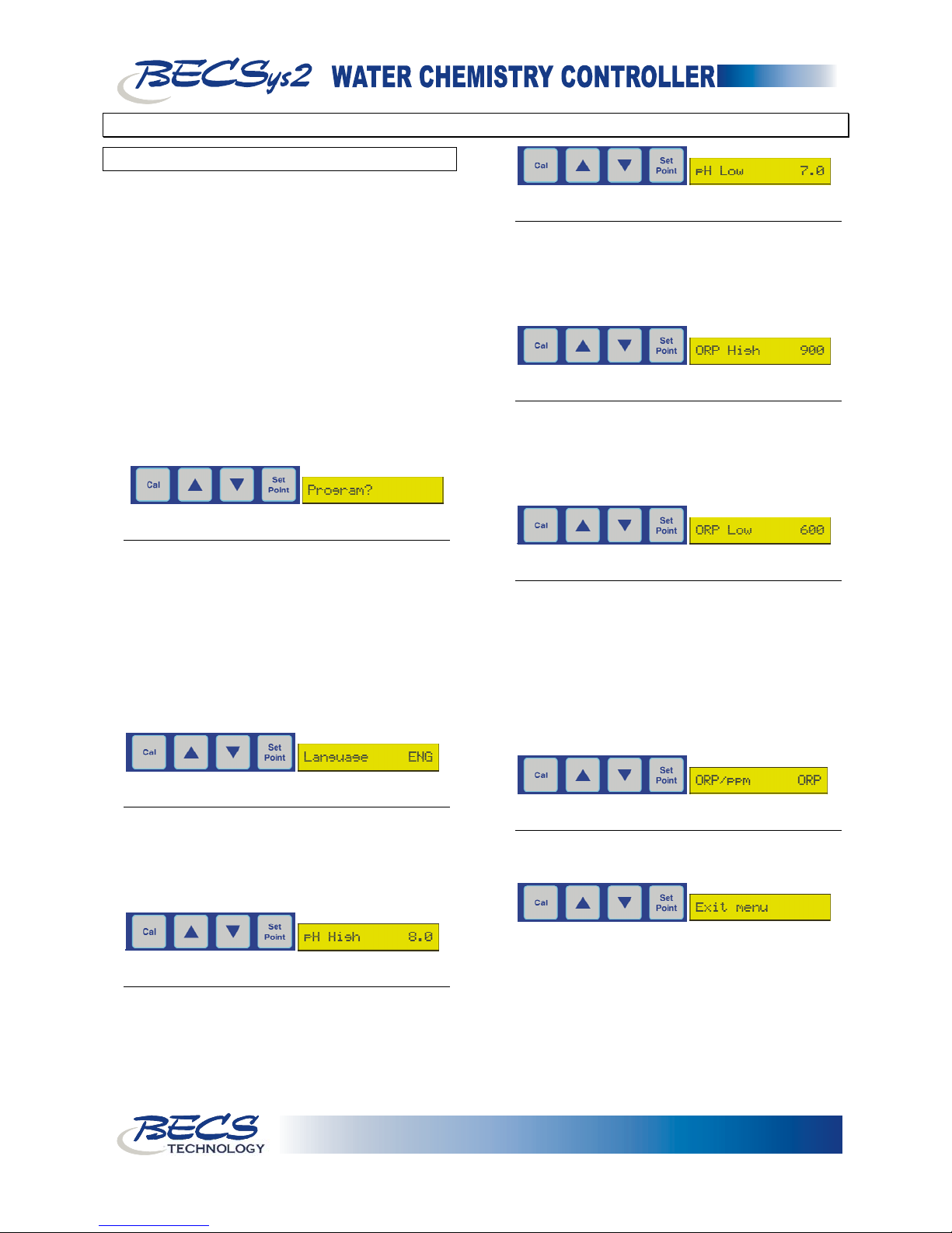
To enter the program menu, press and hold both the
Cal and Up key for 3 seconds. When the LCD
screen clears, release the keys and “Program” should
appear on the display. Press the Up key to enter the
menu and press the Down key to exit. Use the Up
or Down Arrows to scroll to the setting you wish to
change. Press the Cal key to select the setting, then
use the Up or Down Arrows to modify the value.
Press the Cal key again to enter the new value and
return to the menu. To exit the program menu,
scroll to the “Exit menu” option and depress the Cal
key.
NOTE: After five minutes of no programming
activity, the Time-Out feature will automatically
exit the programming menu.
A - 1.1: Selecting Language
The controller can be programmed to display in
three different languages. Once you have entered
the program menu the screen will display
Language ENG, signifying that the display is
currently set to English. Pressing the Cal will
display the question mark (?) before the language.
Use the up and down buttons to select between
ENG (English), ESP (Spanish), and FRA (French),
and press the Cal key to select the language you
would like to use for the display.
A - 1.2: Setting the pH High Alarm Point
Pressing the down arrow displays pH High
followed by the current pH high alarm point. To
change this setting, press the Cal key, use the up or
down arrows to input the value you would like,
then press the Cal key again to save the new value.
A - 1.4: Setting the ORP High Alarm Point
Pressing the down arrow displays ORP High
followed by the current ORP high alarm point. To
change this setting, press the Cal key, use the up or
down arrows to input the value you would like,
then press the Cal key again to save the new value.
A - 1.5: Setting the ORP Low Alarm Point
Pressing the down arrow displays ORP Low
followed by the current ORP low alarm point. To
change this setting, press the Cal key, use the up or
down arrows to input the value you would like,
then press the Cal key again to save the new value.
A - 1.6: ORP/ppm
Pressing the down arrow displays ORP/ppm
selection. This option selects whether to use an
ORP set point or a ppm set point for the main
Cl/Br feed control. It is set to ORP by default.
To change this setting, press the Cal key, use the
up and down arrows to change between ORP and
ppm, then press the Cal key again to save the new
value. This option is only available if configured
to allow ppm control.
A - 1.7: Exiting the Menu
Pressing the Down Arrow displays Exit menu.
Pressing the Cal key exits the programming menu.
A - 1.3: Setting the pH Low Alarm Point
Pressing the down arrow displays pH Low
followed by the current pH low alarm point. To
change this setting, press the Cal key, use the up or
down arrows to input the value you would like,
then press the Cal key again to save the new value.
Page 1
TECHNOLOGY
9487 Dielman Rock Island Industrial Dr. St. Louis, MO 63132 Tel:(314) 567-0088
Page 4
Operator’s Manual
Section B: Normal Operation
B - 1: Displaying the Set Points
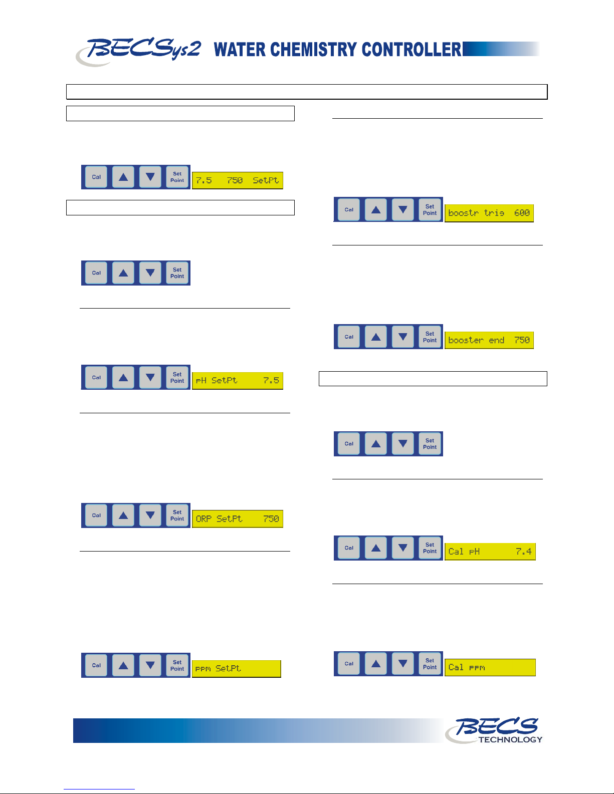
To display the Set Points, press the Set Point key
briefly. The set points will be displayed for three
seconds.
B - 2: Modifying the Set Points
To modify the set points press the Set Point key for
three seconds. The display will change to pH SetPt
followed by the current pH Set Point.
B - 2.1: Modifying the pH Set Point
To change this setting, use the Up or Down
Arrows to input the new value, then press the Set
point key again to save it. To skip entering a new
value, press the Set Point key.
B - 2.2: Modifying the ORP Set Point
If the system is configured to control using an
ORP set point, the screen will display ORP SetPt
followed by the current ORP Set point. To
change this setting, use the Up or Down Arrows
to input the new value, then press the Set point
key again to save it. To skip entering a new value,
press the Set Point key.
B - 2.3: Modifying the ppm Set point
If the system is configured to control using a ppm
set point, the screen will display ppm SetPt and the
current ppm set point on the LED bar graph will
be flashing. To change this setting, use the UP or
Down Arrows to adjust this value shown on the
LED bar graph and press the Set point key again
to save the new value. To skip entering a new
value, press the Set Point key.
B - 2.4: Modifying the Booster Trigger Point
If relay 3 is configured for Cl/Br Booster control,
the screen will display boostr trig followed by the
current trigger point. To change this setting, use
the Up or Down Arrows to input the new value,
then press the Set point key again to save it. To
skip entering a new value, press the Set Point key.
B - 2.5: Modifying the Booster End Point
If relay 3 is configured for Cl/Br Booster control,
the screen will display booster end followed by the
current end set point. To change this setting, use
the Up or Down Arrows to input the new value,
then press the Set point key again to save it. To
skip entering a new value, press the Set Point key.
B - 3: Single Point Calibration
To enter the calibration menu, press and hold the Cal
key for three seconds. After the display clears,
release the Cal key.
B - 3.1: Single Point Calibration - pH
The display should now read Cal pH followed by
the current pH reading. Use the arrow keys to
adjust the displayed value to match your test kit
reading, then press the Cal key to save it.
B - 3.2: Single Point Calibration - ppm
If ppm is available on your unit, the display should
read Cal ppm and the ppm LED's will be flashing.
Use the arrow keys to adjust the LED bar graph to
match your test kit reading, then press the Cal key
to save it.
Page 2
9487 Dielman Rock Island Industrial Dr. St. Louis, MO 63132 Tel:(314) 567-0088
TECHNOLOGY
Page 5
Operator’s Manual
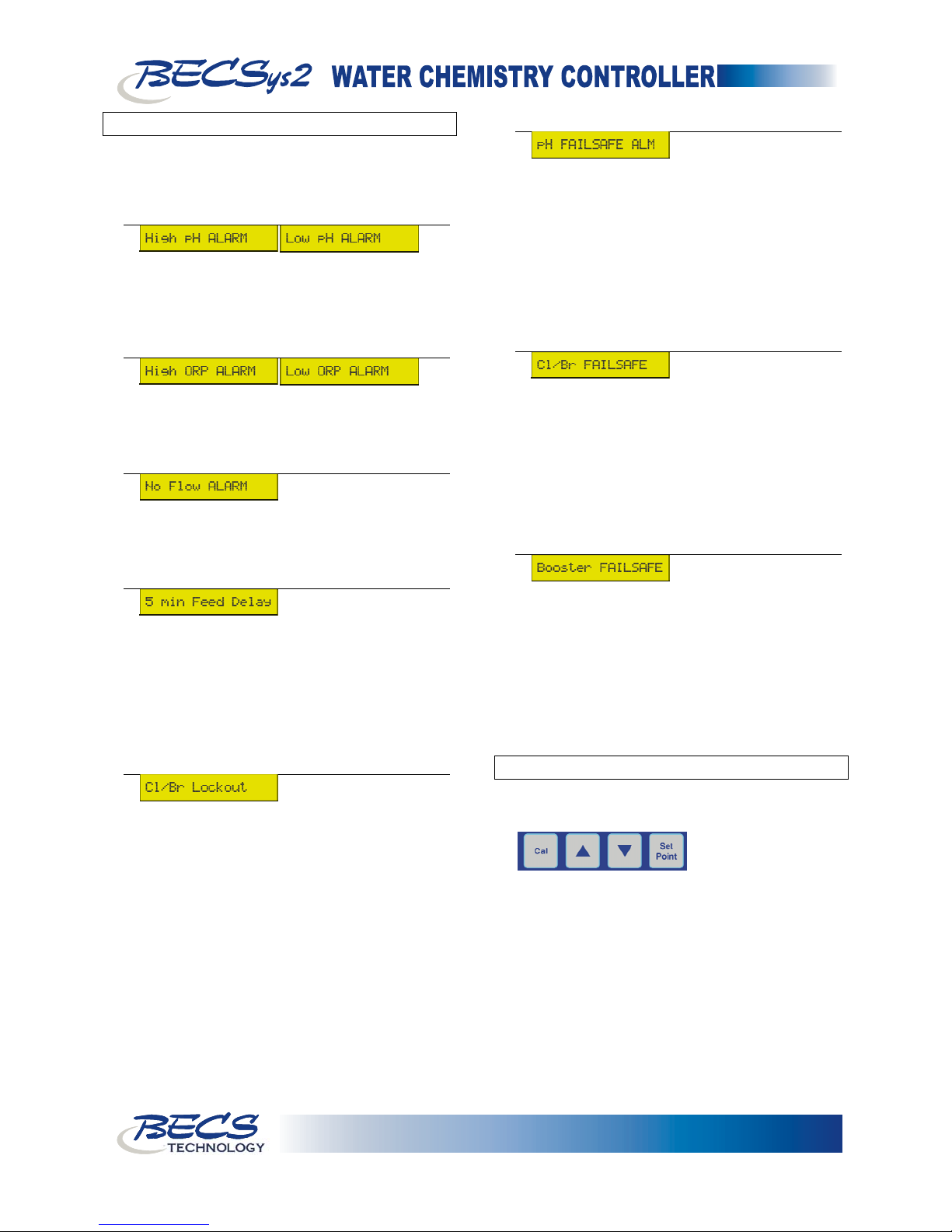
B - 4: Alarms
During normal operation, the following alarms may
be displayed. Some alarms will not be available
depending on the system's configuration.
B - 4.1: pH High/Low alarms
Displayed when the pH input has risen
above/fallen below the pH high/low alarm point.
These alarms will also trigger the Cl/Br Lockout
alarm.
B - 4.2: ORP High/Low alarms
Displayed when the ORP input has risen
above/fallen below the ORP high/low alarm
point.
B - 4.3: No Flow alarm
Displayed when the flow input indicates the flow
has stopped. This alarm disables all chemical
feeds.
B - 4.4: (x) min Feed Delay
When flow is disrupted and then restored, the
controller will delay restarting feeds for a
programmed duration in order to prevent
operating feeds based on readings from stagnant
water. (x) = the number of minutes remaining
before feeds are allowed to start (e.g. 5 min Feed
Delay).
B - 4.5: Cl/Br Lockout
Triggered whenever there is a pH high or low
alarm, this message indicates that the Cl/Br feed
(relay 2) and the optional Cl/Br Booster (relay 3)
are disabled in order to prevent the Cl/Br feeds
from driving the pH even further out of range.
B - 4.6: pH FAILSAFE ALM
Displayed when the active pH feed (feed up or
feed down) attempted to feed continuously for the
selected failsafe duration. The active pH feed is
disabled until one of the following conditions
occurs:
1) The pH input reaches the programmed set
point.
2) Disruption of flow
3) User manually resets the failsafe.
B - 4.7: Cl/Br FAILSAFE
Displayed when the Cl/Br feed attempted to feed
continuously for the selected failsafe duration.
The Cl/Br feed is disabled until one of the
following conditions occurs:
1) The ORP/ppm input reaches the
programmed set point.
2) Disruption of flow
3) User manually resets the failsafe.
B - 4.8: Booster FAILSAFE
Displayed when the optional Cl/Br Booster feed
attempted to feed continuously for the selected
failsafe duration. The Cl/Br Booster feed is
disabled until one of the following conditions
occurs:
1) The ORP input reaches the Cl/Br Booster set
point.
2) Disruption of flow
3) User manually resets the failsafe.
B - 5: Resetting a Failsafe Alarm
To reset a failsafe alarm, press and hold the Up and
Down Arrow keys for two seconds.
Page 3
TECHNOLOGY
9487 Dielman Rock Island Industrial Dr. St. Louis, MO 63132 Tel:(314) 567-0088
Page 6
Operator’s Manual
Section C: Maintenance
The BECSys2 requires no maintenance other than a periodic calibration check and sensor cleaning.
C - 1: Potentiometric Sensors (pH and ORP)
C - 1.1: Electrode Cleaning:
Slow response time and large offsets may indicate the
electrode has become coated. The nature of the
coating will dictate the type of cleaning technique
that should be used.
You may lightly blot the water on a pH sensor
tip on a paper towel, but never vigorously rub
or wipe the pH bulb because this may scratch
the delicate outer layer on the pH glass
impairing its response.
Soft coatings, like bacterial films, are best removed
using a squirt bottle or the water jet from a faucet.
If this is not successful, then gently wipe with a
soft wet cloth.
For a more severe coating, first try a strong
detergent (something similar to Dawn liquid
detergent) and warm water, using a soft brush (like
a toothbrush). Isopropyl alcohol on a Q-tip is
another good choice. Rinse the measuring end in
distilled water before reinstallation.
Greasy and oily coatings are best removed with a
detergent solution or a solvent that will not attack
the sensor body. Methanol and isopropyl alcohol
are good choices for solvents. Acetone, MEK,
THF, or trichloroethane will irreparably harm the
electrode.
Hard coatings, like calcium or lime scale, are best
removed with a solvent appropriate for the
particular coating. A 5% solution of hydrochloric
acid (HCl) would be a good choice for calcium
scale. If unsure of the proper solvent to remove a
hard mineral coating, then alternate between a 5%
hydrochloric acid and a 4% sodium hydroxide
(NaOH) for 10 minutes each. After treating the
electrode with these strong acids or bases, rinse the
electrode with water and soak it in a pH 4 buffer
for at least 1/2 hour.
The platinum tip of an ORP sensor can be cleaned
with an abrasive as a last resort. Gently scour the
platinum with a 600 grit wet emery cloth, or
preferably, a 1-3 micron alumina polishing powder.
C - 1.2: Long-Term Storage:
Save the wetting cap that came with the sensor for
long-term storage. After removing the sensor
from the flow-cell, clean it as in routine
maintenance, then store it in the wetting cap using
a pH 4 buffer saturated with potassium chloride
(KCl). The potassium chloride will prevent
electrolyte from leaching out of the sensors
reference cell. The wetting cap only needs to be
half full. If a number of sites are going to be
serviced, for example, at the end of a season, then
it might be a good idea to carry a pint of 4.0/KCl
storage solution.
Page 4
9487 Dielman Rock Island Industrial Dr. St. Louis, MO 63132 Tel:(314) 567-0088
TECHNOLOGY
Page 7
Operator’s Manual
Section D: Feed Charts
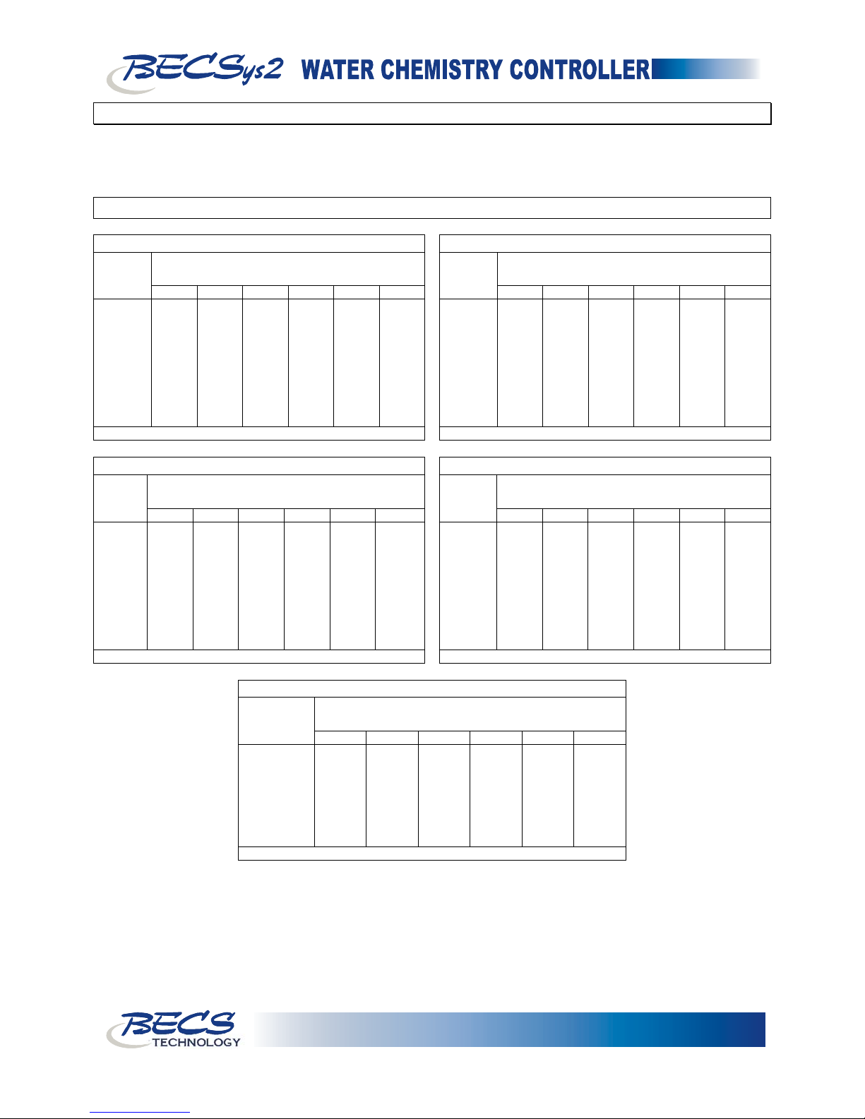
Use the charts on the following pages to determine the correct amount of chemical to add to spa or pool water to
achieve desired conditions. Choose which chart to use by the chemical indicated and the number of gallons to be
treated.
D - 1: Spa Feed Charts
Quantity of Muriatic Acid Needed to Lower Total Alkalinity
Desired
Decrease
In ppm
10 1.25 ts 2.00 ts 1.00 tb 2.00 tb 3.00 tp 0.25 cp
20 2.50 ts 4.00 ts 2.00 tb 0.25 cp 0.33 cp 0.50 cp
30 1.25 tb 2.00 tb 3.00 tb 0.33 cp 0.67 cp 0.75 cp
40 5.00 ts 2.50 tb 0.25 cp 0.50 cp 0.75 cp 1.00 cp
50 2.00 tb 3.00 tb 5.00 tb 0.67 cp 1.00 cp 1.33 cp
60 2.50 tb 0.25 cp 0.33 cp 0.75 cp 1.00 cp 1.50 cp
70 3.00 tb 0.25 cp 0.50 cp 1.00 cp 1.33 cp 1.75 cp
80 3.50 tb 0.33 cp 0.50 cp 1.00 cp 1.50 cp 2.00 cp
90 0.25 cp 0.33 cp 0.67 cp 1.00 cp 1.67 cp 2.33 cp
100 0.25 cp 0.50 cp 0.67 cp 1.33 cp 2.00 cp 2.50 cp
100 150 250 500 750 1000
ts = teaspoon tb = tablespoon cp = one cup (8 fl oz)
Gallons in Spa
Quantity of Bicarbonate of Soda Needed to Raise Total Alkalinity
Desired
Increase
In ppm
10 1.25 ts 2.00 ts 4.00 ts 2.50 tb 0.25 cp 0.33 cp
20 1.00 tb 1.50 tb 2.50 tb 5.00 tb 0.50 cp 0.50 cp
30 1.50 tb 2.00 tb 3.50 tb 0.50 cp 0.67 cp 1.00 cp
40 2.00 tb 3.00 tb 0.33 cp 0.50 cp 1.00 cp 1.00 cp
50 2.50 tb 3.50 tb 6.00 tb 0.75 cp 1.00 cp 1.50 cp
60 3.00 tb 0.25 tb 0.50 cp 1.00 cp 1.33 cp 1.75 cp
70 3.50 tp 0.35 cp 0.50 cp 1.00 cp 1.50 cp 2.00 cp
80 0.25 cp 0.33 cp 0.50 cp 1.25 cp 1.75 cp 2.50 cp
90 0.33 cp 0.50 cp 0.67 cp 1.33 cp 2.05 cp 2.75 cp
100 0.33 cp 0.50 cp 0.75 cp 1.50 cp 2.25 cp 3.00 cp
100 150 250 500 750 1000
ts = teaspoon tb = tablespoon cp = one cup (8 fl oz)
Gallons in Spa
Quantity of Chlorine Compound Needed to Increase 1 ppm
Percent
Chlorine In
Product
5 0.50 tb 2.00 ts 1.25 tb 2.50 tb 0.25 cp 0.33 cp
10 0.25 tb 1.00 ts 2.00 ts 1.25 tb 2.00 tb 2.50 tb
12 0.25 tb 1.00 ts 0.50 tb 1.00 tb 1.50 tb 2.00 tb
30 0.25 tb 0.33 ts 0.75 ts 1.25 ts 2.00 ts 2.50 ts
40 0.167 ts 0.25 ts 0.500 ts 1.00 ts 1.50 ts 2.00 ts
50 0.167 ts 0.25 ts 0.375 ts 0.75 ts 1.25 ts 1.50 ts
60 0.167 tb 0.200 ts 0.375 ts 0.50 ts 1.00 ts 1.25 ts
65 0.100 ts 0.167 ts 0.250 ts 0.50 ts 0.75 ts 1.00 ts
100 150 250 500 750 1000
ts = teaspoon tb = tablespoon cp = one cup (8 fl oz)
Quantity of Sodium Bisulfate Needed to Lower Total Alkalinity
Desired
Decrease
In ppm
10 1.50 ts 2.50 ts 1.00 tb 2.50 tb 0.25 cp 0.33 cp
20 1.00 tb 1.50 tb 2.50 tb 0.33 cp 0.50 cp 0.67 cp
30 1.50 tb 2.50 tb 0.25 cp 0.50 cp 0.75 cp 1.00 cp
40 2.00 tb 3.00 tb 0.33 cp 0.67 cp 1.00 cp 1.25 cp
50 2.50 tb 0.25 cp 0.50 cp 0.75 cp 1.25 cp 1.50 cp
60 3.00 tb 4.50 tb 0.50 cp 1.00 cp 1.50 cp 2.00 cp
70 0.25 cp 0.33 cp 0.50 cp 1.00 cp 1.67 cp 2.25 cp
80 0.25 cp 0.33 cp 0.67 cp 1.25 cp 2.00 cp 2.50 cp
90 0.33 cp 0.50 cp 0.75 cp 1.50 cp 2.25 cp 3.00 cp
100 0.33 cp 0.50 cp 0.75 cp 1.67 cp 2.50 cp 3.25 cp
Quantity of Calcium Chloride Needed to Increase Calcium Hardness
Desired
Increase
In ppm
10 1.25 ts 2.00 ts 1.00 tb 2.00 tb 3.00 tb 0.25 cp
20 2.50 ts 4.00 ts 2.00 tb 0.25 cp 0.33 cp 0.50 cp
30 1.25 tb 2.00 tb 3.00 tb 0.33 cp 0.67 cp 0.75 cp
40 4.00 ts 2.50 tb 0.25 cp 0.50 cp 0.75 cp 1.00 cp
50 2.00 tb 3.00 tb 5.00 tb 0.67 cp 1.00 cp 1.33 cp
60 2.50 tb 0.25 cp 0.33 cp 0.75 cp 1.00 cp 1.50 cp
70 3.00 tp 0.25 cp 0.50 cp 1.00 cp 1.33 cp 1.75 cp
80 3.50 tp 0.25 cp 0.50 cp 1.00 cp 1.50 cp 2.00 cp
90 0.25 cp 0.33 cp 0.33 cp 1.00 cp 1.67 cp 2.33 cp
100 0.25 cp 0.50 cp 0.67 cp 1.33 cp 2.00 cp 2.50 cp
Gallons in Spa
100 150 250 500 750 1000
ts = teaspoon tb = tablespoon cp = one cup (8 fl oz)
100 150 250 500 750 1000
ts = teaspoon tb = tablespoon cp = one cup (8 fl oz)
Gallons in Spa
Gallons in Spa
Page 5
TECHNOLOGY
9487 Dielman Rock Island Industrial Dr. St. Louis, MO 63132 Tel:(314) 567-0088
Page 8
Operator’s Manual
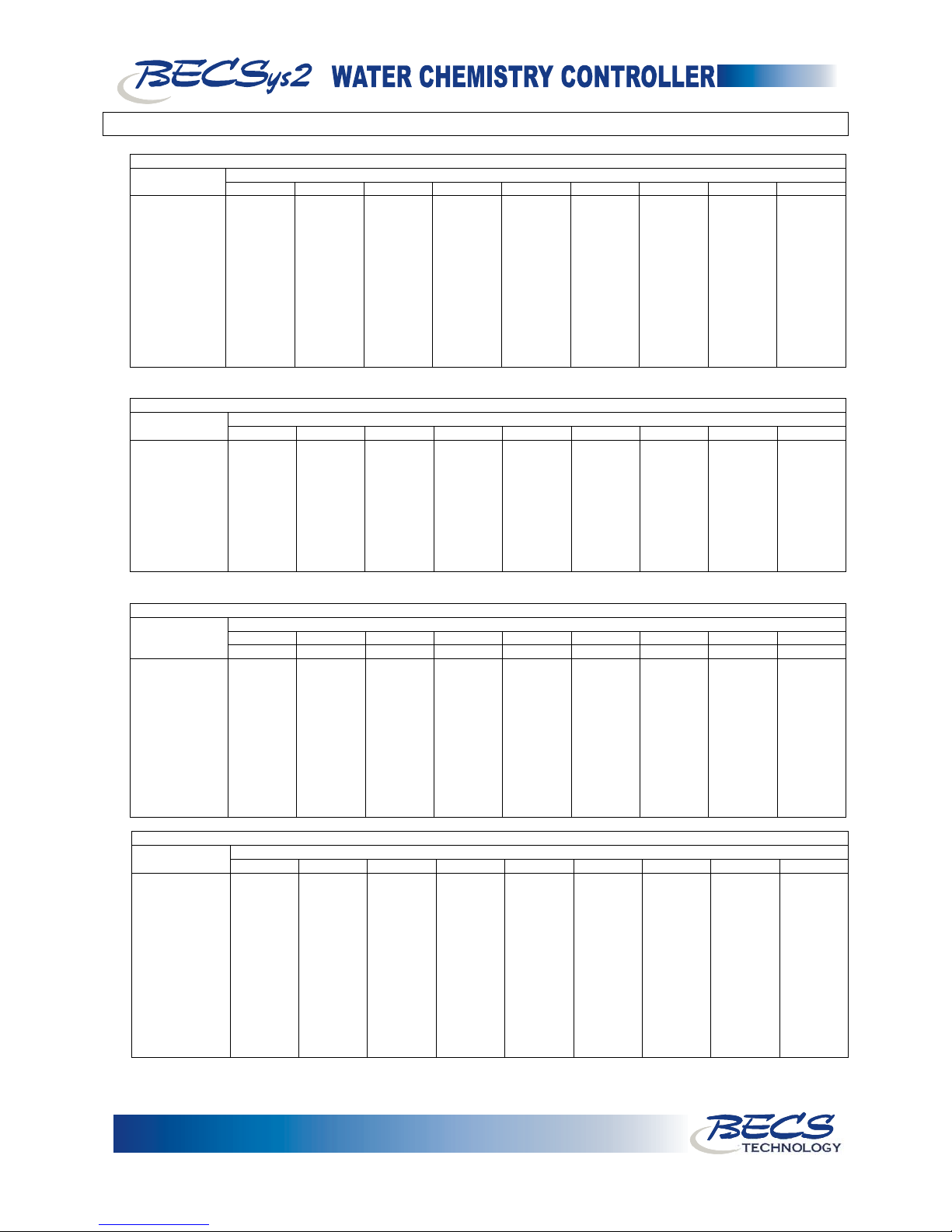
D - 2: Pool Feed Charts
In ppm
10 1.30 pt 1.62 qt 3.25 qt 1.22 gl 1.62 gl 3.25 gl 8.13 gl 12.20 gl 16.25 gl
20 1.30 pt 3.25 qt 1.62 gl 2.43 gl 3.25 gl 7.50 gl 16.20 gl 24.30 gl 32.50 gl
30 1.95 qt 1.22 gl 2.44 gl 3.86 gl 4.98 gl 9.76 gl 24.40 gl 36.60 gl 48.80 gl
40 2.80 qt 1.63 gl 3.25 gl 4.87 gl 6.50 gl 13.00 gl 32.50 gl 48.80 gl 65.00 gl
50 3.25 qt 2.03 gl 4.07 gl 6.10 gl 8.14 gl 16.28 gl 40.70 gl 61.00 gl 81.40 gl
60 3.90 qt 2.44 gl 4.88 gl 7.32 gl 9.76 gl 19.52 gl 48.80 gl 73.20 gl 97.80 gl
70 1.14 gl 2.84 gl 5.69 gl 8.54 gl 11.38 gl 22.76 gl 56.90 gl 85.45 gl 113.80 gl
80 1.30 gl 3.25 gl 6.50 gl 9.75 gl 13.00 gl 26.00 gl 65.00 gl 97.50 gl 138.00 gl
90 1.48 gl 3.66 gl 7.31 gl 10.96 gl 14.82 gl 29.24 gl 73.10 gl 109.60 gl 146.20 gl
100 1.63 gl 4.06 gl 8.12 gl 12.18 gl 16.24 gl 32.48 gl 81.20 gl 121.80 gl 162.40 gl
120 1.96 gl 4.88 gl 9.76 gl 14.64 gl 19.52 gl 39.00 gl 97.80 gl 148.40 gl 196.20 gl
150 2.44 gl 6.09 gl 12.18 gl 18.27 gl 24.40 gl 48.80 gl 121.80 gl 182.70 gl 244.00 gl
200 3.25 gl 8.12 gl 18.24 gl 24.36 gl 32.50 gl 65.00 gl 162.40 gl 243.80 gl 325.00 gl
In ppm
10 1.50 lb 3.75 lb 7.50 lb 11.25 lb 15.00 lb 30.00 lb 75.00 lb 112.50 lb 150.00 lb
20 3.00 lb 7.50 lb 15.00 lb 22.50 lb 30.00 lb 60.00 lb 150.00 lb 225.00 lb 300.00 lb
30 4.50 lb 11.25 lb 22.50 lb 33.75 lb 45.00 lb 90.00 lb 225.00 lb 337.50 lb 450.00 lb
40 6.00 lb 15.00 lb 30.00 lb 45.00 lb 60.00 lb 120.00 lb 300.00 lb 450.00 lb 600.00 lb
50 7.50 lb 18.75 lb 37.50 lb 56.25 lb 75.00 lb 150.00 lb 375.00 lb 562.50 lb 750.00 lb
60 9.00 lb 22.50 lb 45.00 lb 67.50 lb 90.00 lb 180.00 lb 450.00 lb 675.00 lb 900.00 lb
70 10.50 lb 26.25 lb 52.50 lb 78.75 lb 105.00 lb 210.00 lb 525.00 lb 787.50 lb 1050.00 lb
80 12.00 lb 30.00 lb 60.00 lb 90.00 lb 120.00 lb 240.00 lb 600.00 lb 900.00 lb 1200.00 lb
90 13.50 lb 33.75 lb 67.50 lb 101.25 lb 135.00 lb 270.00 lb 675.00 lb 1012.50 lb 1350.00 lb
100 15.00 lb 37.50 lb 75.00 lb 112.50 lb 150.00 lb 300.00 lb 750.00 lb 1125.00 lb 1500.00 lb
Desired Increase
In ppm
10 1 4 3 2 6 4 9 6 12 8 25 62 8 93 12 125
20 2 8 6 4 12 8 18 12 25 0 50 125 0 197 8 250
30 3 12 9 6 18 12 28 2 37 8 75 187 8 281 4 375
40 5 0 12 8 25 0 37 8 50 0 100 250 0 375 0 500
50 6 4 15 10 31 4 46 14 62 8 125 312 8 468 12 625
60 7 8 18 12 37 8 56 4 75 0 150 375 0 562 8 750
70 8 12 21 14 43 12 65 10 87 8 175 437 8 658 4 875
80 10 0 25 0 50 0 75 0 100 0 200 500 0 750 0 1,000
90 11 4 28 2 56 4 84 6 112 8 225 562 8 843 12 1,125
100 12 8 31 4 62 8 93 12 125 0 250 625 0 937 8 1,250
150 18 12 46 14 93 12 104 10 187 8 375 937 8 1,406 4 1,875
200 25 0 62 8 125 0 187 8 250 0 500 1,250 0 1,875 0 2,500
In Product
5 3.2 cp 2 qt 1 gl 1.5 gl 2 gl 4 gl 10 gl 15 gl 20 gl
10 1.6 cp 1 qt 2 qt 3 qt 1 gl 2 gl 5 gl 7.5 gl 10 gl
12 1.33 cp 1.67 pt 1.517 qt 2.276 pt 3.33 qt 1.665 gl 4.163 gl 6.245 gl 8.326 gl
30 0.278 lb 0.665 lb 1.390 lb 2.085 lb 2.780 lb 5.580 lb 13.900 lb 20.850 lb 27.800 lb
40 0.209 lb 0.521 lb 1.043 lb 1.565 lb 2.086 lb 4.172lb 10.430 lb 15.645 lb 20.860 lb
50 0.167 lb 0.417 lb 0.834 lb 1.251 lb 1.668 lb 3.336lb 8.340lb 12.511 lb 16.680 lb
60 0.139 lb 0.348 lb 0.695 lb 1.043 lb 1.390 lb 2.780lb 6.950 lb 10.425 lb 13.900 lb
65 0.128 lb 0.321 lb 0.642 lb 0.963 lb 1.284 lb 2.568lb 6.420 lb 9.630lb 12.840 lb
70 0.119 lb 0.298 lb 0.596 lb 0.894 lb 1.192 lb 2.384lb 5.960lb 8.940 lb 11.920 lb
75 0.111 lb 0.278 lb 0.556 lb 0.834 lb 1.112 lb 2.224 lb 5.560 lb 8.340 lb 11.120 lb
80 0.104 lb 0.261 lb 0.521 lb 0.782 lb 1.042 lb 2.064 lb 5.210 lb 7.815 lb 10.420 lb
85 0.096 lb 0.417 lb 0.491 lb 0.737 lb 0.982 lb 1.964 lb 4.910 lb 7.365 lb 9.829 lb
90 0.093 lb 0.232 lb 0.463 lb 0.695 lb 0.926 lb 1.852 lb 4.630 lb 6.945 lb 9.260 lb
100 0.083 lb 0.209 lb 0.417 lb 0.626 lb 0.634 lb 1..668 lb 4.170 lb 6.225lb 8.340 lb
10,000 25,000 50,000 75,000 100,000 200,000 500,000 750,000 1,000,000
10,000 25,000 50,000 75,000 100,000 200,000 500,000 750,000 1,000,000
10,000 25,000 50,000 75,000 100,000 200,000 500,000 750,000 1,000,000
lb oz lb oz lb oz lb oz lb oz lb lb oz lb oz lb
10,000 25,000 50,000 75,000 100,000 200,000 500,000 750,000 1,000,000
Quantity of Muriatic Acid Needed to Lower Total Alkalinity
Gallons in Pool Desired Decrease
pt = one pt (16 fl oz) qt = one quart (32 fl oz) gl = one gallon (128 fl oz)
Quantity of Bicarbonate of Soda Needed to Raise Total Alkalinity
Gallons in Pool Desired Increase
lb =pounds of dry chemical
Quantity of Calcium Chloride Needed to Increase Calcium Hardness
Gallons in Pool
Quantity of Chlorine Compound Needed to Increase 1 ppm
Gallons in Pool Percent Chlorine
cp = one cup (8 fl oz) pt = one pt (16 fl oz) qt = one quart (32 fl oz)
gl = one gallon (128 fl oz) lb =pounds of dry chemical
Page 6
9487 Dielman Rock Island Industrial Dr. St. Louis, MO 63132 Tel:(314) 567-0088
TECHNOLOGY
Page 9
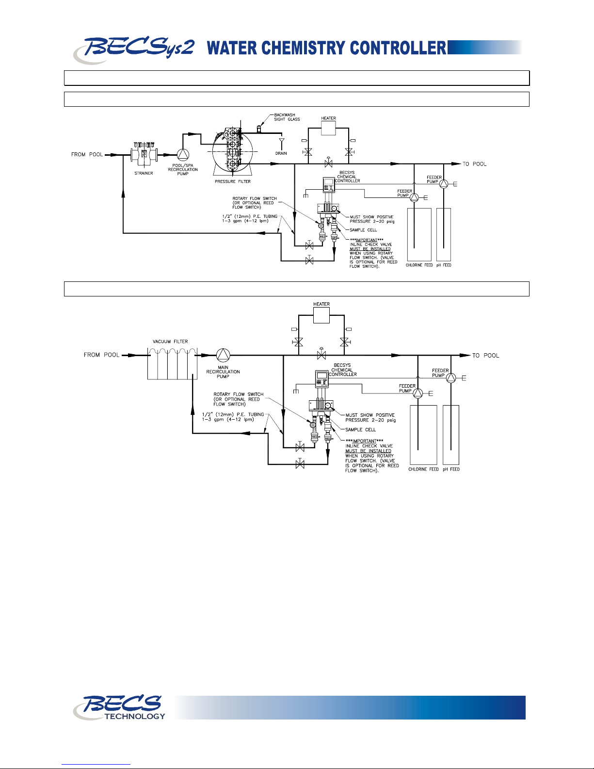
Operator’s Manual
E - 1: Pressure Filter Installation
E - 2: Vacuum Filter Installation
Section E: Installation Diagrams
Page 7
TECHNOLOGY
9487 Dielman Rock Island Industrial Dr. St. Louis, MO 63132 Tel:(314) 567-0088
Page 10

Operator’s Manual
Section F: Warranty
LIMITED WARRANTY
BECS warrants the controller electronics and flow cell against any defect in workmanship or
materials for a period of two years from the date of shipment. BECS warrants the pH and ORP
sensors against any defect in workmanship or materials for a period of one year from the date of
shipment. In the event of a component failure due to any defect in workmanship or materials,
BECS will repair, or if repair is not possible, replace the defective part or parts of the BECSys
controller.
BECS will have the sole right to determine whether to repair or replace a product. BECS will not be
responsible for any expense associated with installation of repaired or replacement parts.
LIMITATIONS AND EXCLUSIONS
This is a LIMITED WARRANTY. BECS makes NO WARRANTIES other than those contained
herein. The LIMITED WARRANTY replaces and is in lieu of any WARRANTIES of
MERCHANTABILITY or of FITNESS FOR A PARTICULAR PURPOSE which are expressly
DISCLAIMED. All GENERAL, SPECIAL, INDIRECT, INCIDENTAL AND/OR
CONSEQUENTIAL DAMAGES ARE EXCLUDED AND DISCLAIMED.
This Limited Warranty is governed by Missouri Law and all disputes related to or arising from this
transaction or Limited Warranty shall be resolved in Circuit Court of St. Louis County, Missouri.
Any claims under this Limited Warranty must be brought within ONE YEAR after the cause of
action accrued.
Page 8
9487 Dielman Rock Island Industrial Dr. St. Louis, MO 63132 Tel:(314) 567-0088
TECHNOLOGY
Page 11

Operator’s Manual
.
BECS
TECHNOLOGY Inc
has been designing and manufacturing the industry’s
most reliable water chemistry controller for over 15 years. Our 24,000 ft2 facility in
Saint Louis, Missouri is home to an exceptional design team, and all manufacturing is
performed onsite at this facility where we can personally assure the quality of our
products. The BECS commitment to excellence drives the most innovative new
products and unparalleled customer service.
August 2006
TECHNOLOGY
9487 Dielman Rock Island Industrial Dr. St. Louis, MO 63132 Tel:(314) 567-0088
Document Part Number: 9620007-H06
 Loading...