

Page 1
b
MICRO BOOSTER ONBOARD PREAMP
FOR GUITAR & BASS
INSTALLATION MANUAL
SPECIFICATIONS
Input impedance: >1MΩ
Output Impedance: ~10KΩ
Battery Voltage: 9VDC ±10% up to 18VDC
Recommended Battery: Alkaline
Power Consumtion: 1mAh in use; 0.1mAh without input signal
Product Size: Lenght: 32.5mm, Depth: 25mm, Height: 25mm
Product Weight: 30 gr.
Packed Weight: 135 gr.
RoHS Compliance
ADVICE, WARNING & CAUTIONS
- USE WIRING DIAGRAMS FROM OUR WEBSITE AS STARTING
POINT!
- Read this manual before installation and keep it handy.
- Never pull up the push-push switch-pot by force.
- Remove the knob from the switch-pot only when switch is in UP
position.
- Do not exceed 19VDC when powering booster's circuit.
- We recommend using metal shielding where the preamp is to be
installed.
- When soldering and desoldering do not overheat the circuit boards
or any electronic component.
- If sharp tools are to be used in installation, handle with care and
never use force to have things done.
- Make sure the battery is properly attached to the battery snap-on
connector.
- Do not place the electronic circuit & battery in direct sunlight, in
extreme temperature and humidity conditions, or in dusty
environment.
- Do not make modifications to the circuit and do not install the
preamp in any other way except as described in this manual.
- This manual may be changed or modified without notice so we
advise you to download it from the website before installation.
INTRODUCTION
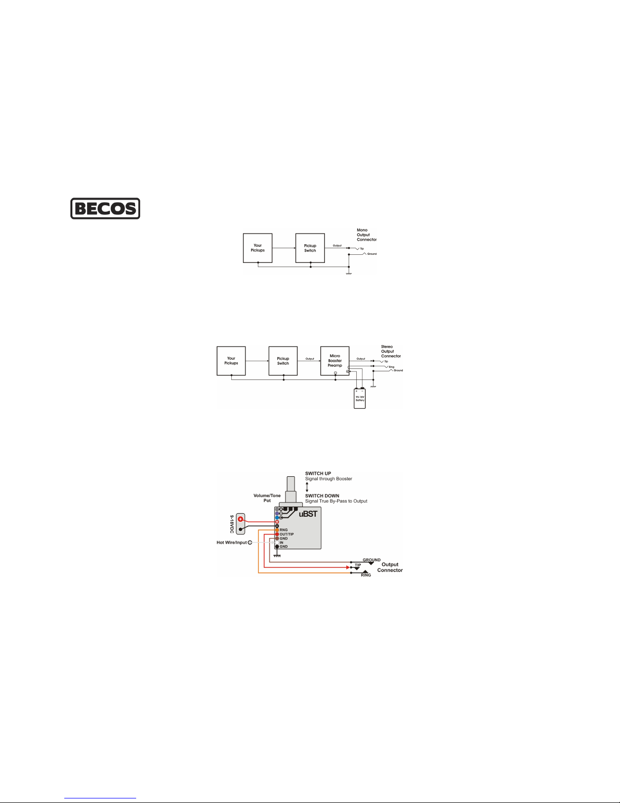
Usually, your guitar is wired like this:
The booster will come latest in the guitar signal path, after the
pickups, volume & tone controls and pickup switch. Its electronic
circuit board is soldered on a Push-Push switch-pot. Push once - the
signal goes through booster circuit (the knob will go a little higher, so
you will notice the booster is engaged); push again - the signal is in
TRUE BYPASS - when switch is off, signal is wire-routed straight to
the output jack.
The potentiometer side of the switch-pot IS NOT part of booster's
circuit, and is meant to replace volume or tone potentiometer in
your instrument for the convenience of having a routing switch and a
potentiometer i n one device. Potentiometer has to be rewired j ust
as it used to be - passive. If it is the tone control that is put in place
of, the tone capacitor has to be moved to the new pot as well.
A 10 pin header connector is available on booster's PCB. Starting
from top to bottom while watching the SMD side of the circuit
board, as shown above, these pins are:
A, B, C - corresponding to potentiometer lugs (which will replace
actual potentiometer in your guitar). This is where wires Gray, Purple
and Blue will be connected. These pins in the header connector are
doubled by soldering h
oles on the circuit board. They also help to
install the capacitor or hot wire, depending where you install the
booster in your guitar. A & C are swappable if installed as tone pot.
+ and - for connecting the battery. Red wire is positive, Black wire is
negative.
RNG (ring), OUT (tip), GND with corrsponding Orange, Red, Brown
wires connect the stereo output connector of the instrument. When
instrument cable is inserted, Ring to Ground powers booster circuit.
IN and GND are the points where White hot wire and Black ground
wire will be connected. This wire puts switch-potentiometer,
booster circuit and the negative side of the battery to guitar's main
ground.
All these colored wires are supplied and will be connected to the pinhead connector for a convenient and easy installation.
The mono output connector in the guitar will be replaced as well
with an already wired and included stereo connector. This stereo
connector sends power to booster's circuit as long as guitar cable is
inserted. The instrument's cable plug has to be mono TRS plug.
PREPARATION
We strongly recommend you to shield the electronics compartiment
in your instrument with sticky cooper shielding foil, if it's not done
from the factory already.
Be sure to connect this shielding to guitar's main ground point.
By now, you've probably chosen which control you are going to
replace: the tone or the volume pot of your instrument.
INSTALLATION
We provide a handful of Wiring Diagrams on product's web page.
Please consult them first! Most likely you will find your setup right
there.
We remind you that potentiometer side of the switch-pot is not
part of booster's circuit, and is going to remain passive in your
guitar circuit as before. The switch side of the switch-pot is used to
Page 2

route pickup signal through the booster or true by-pass to the
output connector of the instrument.
1. Draw your present wiring on a piece of paper.
2. Prepare a diagram for booster installation before doing any
unsolderings. Start with the provided wiring diagrams on product
web page.
3. Use the supplied colored wires and solder their ends to guitar's
circuit; the other end will be just attached to the pin header
connector on the booster's board.
4. Fix the output stereo connector to the metal plate at guitar's
output hole.
5. Place and secure the Micro Booster Preamp in place of the
original pot, leaving room for the 9V battery (or two batteries in
series, if you wish to increase headroom to 18V) and have the
preamp's gain knob leveled.
6. Use the battery fixing clip provided to secure the battery in
between the electronics. We recommend sticking this metal clip to
the plastic electronics cover.
7. Connect the battery to the snap-on connector and the Red and
Black wires to the pin header connector as indicated in the image in
this manual or the schematic downloaded from product web page.
Booster's circuit will be powered as long as guitar cable is inserted
into the output (stereo) connector. The plug on the instrument cable
has to be a mono TRS plug.
FINAL TOUCH
You may notice that booster's gain setting is made with a knob that
has a long sliding shaft, which may help get the knob through the
plastic cover or pickguard, for an easy setting. That can be very
useful when changing the sounds and amps on a regular basis, such
as when in studio or on the road. However, the Unity Gain trimmer
can only be set when you have full access to the circuit board and is
supposed to stay untouched. You may use it for attenuation as well.
If you want to take the Gain knob trough front pickguard, the hole
has to be 6 mm diameter and is to be at aproximately 11 mm from
the center of the potentiometer's shaft; it will be just near the
control knob (tone or volume). Try to align this hole on the same axis
that aligns all other controls of the guitar, for an aesthetically
pleasing result. Take out the knob through pickguard as much as
needed.
If the k nob is to be taken through the plastic cover on the back side
of your guitar, you may vertically align the top of the knob flush with
the cover, so the knob won't rub your clothes. Fix it to the desired
length with a small drop of glue.
SET UP
Booster's gain is is set from the Gain knob. It starts by default from
Unity Gain and goes up to +20dB of amplification. The variation is
logarithmic.
IN OPERATION
BECOS Micro Booster is configured for clean flat boost, even in all
audio spectrum. Each playing style or gear setup change may
require booster setting adjustments, because everything interacts
with each other.
When engaged, a modestly gained clean channel of an amp gets
louder, pushing t he break-up. Engaging t he Micro Boost in front of
an amp set on a cranked channel puts you in the spotlight instantly.
The higher the gain set on the amp, the more fat & saturated
distortion you get, with increased sustain and plenty of warm
harmonics.
On high gain, booster's effect is less obvious in volume, yet more
obvious in creamy saturation overdrive, due to amp's natural
compression. You will most likely feel that you can play faster and
easier.
YOUR FEEDBACK, PRODUCT REGISTRATION & SUPPORT
We will always appreciate any direct feedback from you. Please let
us know how you use our products, how satisfied you are and how
can we improve in making things better. Don't forget to register your
product to receive full e-mail support and updates when they are
available.
MICRO BOOSTER ONBOARD PREAMP
FOR GUITAR & BASS
INSTALLATION MANUAL
Version 2.1
Please check and download latest manual!
Use wiring diagrams published on product web page as
a starting point.
Thank you for using BECOS products!
Designed & Hand Made in Romania/EU
www.becos.ro
 Loading...