

Page 1
Application Guide
M-6200A B-2355 Series
Cooper Hardware Kit
Installation Instructions
Page 2
WARNING
DANGEROUS VOLTAGES, capable of causing death or serious
injury, are present on the external terminals and inside the equipment. Use extreme caution and follow all safety rules when handling, testing or adjusting the equipment. However, these internal
voltage levels are no greater than the voltages applied to the external terminals.
DANGER! HIGH VOLTAGE
– This sign warns that the area is connected to a dangerous high voltage, and you
must never touch it.
PERSONNEL SAFETY PRECAUTIONS
The following general rules and other specific warnings throughout the manual must be followed during application,
test or repair of this equipment. Failure to do so will violate standards for safety in the design, manufacture, and intended
use of the product. Qualified personnel should be the only ones who operate and maintain this equipment. Beckwith
Electric Co., Inc. assumes no liability for the customer’s failure to comply with these requirements.
– This sign means that you should refer to the corresponding section of the operation
manual for important information before proceeding.
Always Ground the Equipment
To avoid possible shock hazard, the chassis must be connected to an electrical ground. When servicing
equipment in a test area, the Protective Earth Terminal must be attached to a separate ground securely
by use of a tool, since it is not grounded by external connectors.
Do NOT operate in an explosive environment
Do not operate this equipment in the presence of flammable or explosive gases or fumes. To do so would
risk a possible fire or explosion.
Keep away from live circuits
Operating personnel must not remove the cover or expose the printed circuit board while power is applied. In no case may components be replaced with power applied. In some instances, dangerous voltages may exist even when power is disconnected. To avoid electrical shock, always disconnect power and
discharge circuits before working on the unit.
Exercise care during installation, operation, & maintenance procedures
The equipment described in this manual contains voltages high enough to cause serious injury or death.
Only qualified personnel should install, operate, test, and maintain this equipment. Be sure that all personnel safety procedures are carefully followed. Exercise due care when operating or servicing alone.
Do not modify equipment
Do not perform any unauthorized modifications on this instrument. Return of the unit to a Beckwith
Electric repair facility is preferred. If authorized modifications are to be attempted, be sure to follow
replacement procedures carefully to assure that safety features are maintained.
Page 3

PRODUCT CAUTIONS
Before attempting any test, calibration, or maintenance procedure, personnel must be completely familiar
with the particular circuitry of this unit, and have an adequate understanding of field effect devices. If a
component is found to be defective, always follow replacement procedures carefully to that assure safety
features are maintained. Always replace components with those of equal or better quality as shown in the
Parts List of the Instruction Book.
Avoid static charge
This unit contains MOS circuitry, which can be damaged by improper test or rework procedures. Care
should be taken to avoid static charge on work surfaces and service personnel.
Use caution when measuring resistances
Any attempt to measure resistances between points on the printed circuit board, unless otherwise noted
in the Instruction Book, is likely to cause damage to the unit.
Page 4

B-2355 Cooper – Table of Contents
TABLE OF CONTENTS
M‑6200A Application Guide
B‑2355 Series Cooper Hardware Kit
Installation Instructions
1.0 Introduction ..................................................................................................................................1
2.0 Mechanical/Physical Information ...............................................................................................1
Figure 1 M-6200A Outline Dimensions ...................................................................................2
Figure 2 M-6200A Rear Layout ..............................................................................................3
3.0 External Connections ..................................................................................................................4
Terminal Block Assignments
Typical Connections
Grounding
Unit Isolation
Torque Requirements
Control Power Backup Input Connection
Backup Power Requirements
Figure 3 Typical Connections for Cooper CL-2, CL-2A,
CL-4A, CL-4B, CL-4C, CL-5 and CL-6 Regulator Controls
Terminal Block Assignments (TB1)
Non-Sequential Operation
Auto Tapchange Inhibit
Auxiliary Input (Aux 2)
Table 1 Multi-Step Voltage Reduction External Connections ..................................................7
Auxiliary Input (Aux 1)
Terminal Block Assignments (TB2)
Figure 4 Typical Control Power Backup Connection for M-6200A
Utilizing M-2026 or M-2027 Supply
Figure 5 B-0920 Control Power Backup Input 3-Wire Harness ............................................10
.....................................................................................................................................4
.......................................................................................................................4
..................................................................................................................................4
..........................................................................................................4
.....................................................................................................................4
......................................................................................4
.........................................................................................................5
.......................................................6
...............................................................................................7
.............................................................................................................7
...................................................................................................................7
....................................................................................................................7
....................................................................................................................7
...............................................................................................9
.........................................................................................10
4.0 Cooper CL-2, CL-2A, CL-4A, CL-4B, CL-4C, CL-5 and CL-6 Regulator Controls
Replacement ...............................................................................................................................11
Application
Typical Connections
External Connections
Lightning Protection
Non-Sequential Operation/ Counter Input
Multi-Step Voltage Reduction
Removal of the Cooper Control....................................................................................................12
Figure 6 Cooper Control in Cabinet ......................................................................................13
Installing the M-6200A in a Cooper Regulator
B-2355-C1/B-2355-C2 Hardware Kit Configuration
Table 2 B-2355-C1 and B-2355-C2 Hardware Kit .................................................................14
Figure 7 B-2355-C1/B-2355-C2, B-2355-C3/B-2355-C4 Hardware Kit Orientation .............15
Figure 8 M-6200A (B-1128) Cooper Wiring Harness (Fanning Strip) for CL-2 through
CL-5 Regulators ......................................................................................................................16
Figure 9 M-6200A (B-1157) Cooper Wiring Harness (Gray Plug) for CL-6 Regulators ........17
...................................................................................................................................11
.....................................................................................................................11
...................................................................................................................11
.....................................................................................................................11
....................................................................................11
......................................................................................................12
.............................................................................13
.....................................................................14
i
Page 5

M-6200A Application Guide
B-2355-C3/B-2355-C4 Hardware Kit Configuration .....................................................................18
Table 3 B-2355-C3 and B-2355-C4 Hardware Kit .................................................................18
Figure 10 B-2355-C3 (B-1255 and B-1259) Cooper Wiring Harness ...................................19
Figure 11 B-2355-C4 (B-1255 and B-1260) Cooper Wiring Harness ...................................20
5.0 TapTalk S-6200 Communications Software Installation .........................................................21
Starting TapTalk
...........................................................................................................................21
Figure 12 S-6200 TapTalk Program-Item Icon ......................................................................21
6.0 Activating Initial Local Communications .................................................................................21
Figure 13 USB Port Connection Dialog Screen ....................................................................22
Figure 14 Failed to Connect Error Screen ............................................................................22
Figure 15 Failed to perform Access Code Verification Error Screen ....................................23
Figure 16 Successfully Connected Read-Only Access Screen ............................................23
Appendix
A HMI
A.1 HMI Menu Flow ........................................................................................................................ A–2
Figure A-1 Monitor Menu Flow .......................................................................................... A–2
Figure A-2 Setpoints Menu Flow ...................................................................................... A–3
Figure A-3 Configuration Menu Flow (1 of 2)..................................................................... A–4
Figure A-3 Configuration Menu Flow (2 of 2)..................................................................... A–5
Figure A-4 Communication Menu Flow ............................................................................. A–6
Figure A-5 Utilities Menu Flow ........................................................................................... A–7
A.2 HMI Screen Review ................................................................................................................. A–8
Monitor/Metering
Monitor/Present Demand
Monitor/Demand History
....................................................................................................................... A–8
.......................................................................................................... A–9
........................................................................................................... A–9
Monitor/Energy Metering......................................................................................................... A–10
Monitor/Status
Monitor/Motor Current
Monitor/Harmonics
Monitor/Tap Information
Setpoints/Profile Settings
Setpoints/Common Settings
Setpoints/Power Flow Forward
Setpoints/Power Flow Reverse
Setpoints/Voltage Reduction
Setpoints/Limits
......................................................................................................................... A–11
............................................................................................................. A–14
.................................................................................................................. A–14
.......................................................................................................... A–15
........................................................................................................ A–17
................................................................................................... A–17
............................................................................................... A–18
............................................................................................... A–18
................................................................................................... A–19
....................................................................................................................... A–20
ii
Page 6

B-2355 Cooper – Table of Contents
Setpoints/VAr Bias .................................................................................................................. A–20
VAr Bias (Step)
VAr Bias (Linear)
Configuration/Tapchanger Type
Configuration/Tap Settings
Configuration/Programmable Alarm
Configuration/System Clock
Configuration/Mtr Current Profile
Configuration/CBEMA Setup
Configuration/Harmonics Setup
Configuration/Data Logging
Configuration/Run Through Neutral
Configuration/Nameplate
Communication/Comm Settings
Communication/Memory Card
Communication/Ethernet
Communication/HMI
Communication/Bluetooth
Communication/RS232
Utilities/Calibration-Test
Utilities/About
....................................................................................................................... A–20
..................................................................................................................... A–21
.............................................................................................. A–22
...................................................................................................... A–22
........................................................................................ A–24
.................................................................................................... A–24
............................................................................................ A–24
.................................................................................................. A–25
.............................................................................................. A–25
.................................................................................................... A–26
........................................................................................ A–27
........................................................................................................ A–27
............................................................................................. A–30
................................................................................................ A–31
........................................................................................................ A–32
............................................................................................................... A–34
....................................................................................................... A–34
........................................................................................................... A–35
.......................................................................................................... A–36
.......................................................................................................................... A–38
iii
Page 7

M-6200A Application Guide
© 2010 Beckwith Electric Co. All Rights Reserved.
Printed in U.S.A. (07.30.01)
iv
800-B-2355-AG-05 04/17
Page 8

1.0 Introduction
This Application Guide is intended for those personnel that are responsible for the installation
of the M-6200A Digital Regulator Control. It provides the mechanical orientation of inputs
and outputs as well as physical dimensions of the control. External connections to the
control are detailed to assist installation personnel with various applications of the control.
The M-6200A through the use of hinge brackets, a latch bracket where required and a unit
specific wiring harness allow the unit to directly replace Cooper CL-2, CL-2A, CL-4A, CL-4B,
CL-4C, CL-5 and CL-6 regulator controls.
Detailed instructions are provided for those specific applications where the M-6200A is
directly replacing Cooper controls.
Also provided are instructions for the installation of TapTalk S-6200 Communications
Software and establishing initial local communications with the target control.
2.0 Mechanical/Physical Information
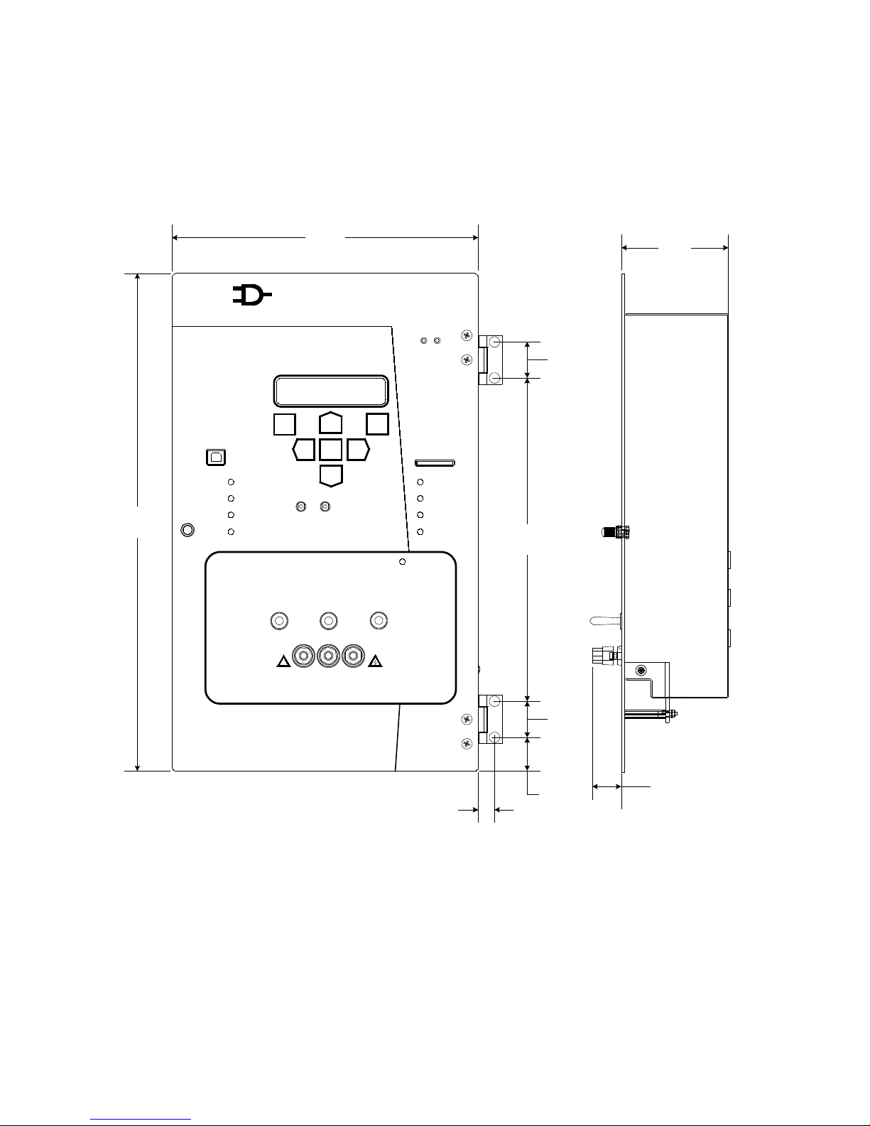
The M-6200A Regulator Control physical dimensions are illustrated in Figure 1. General
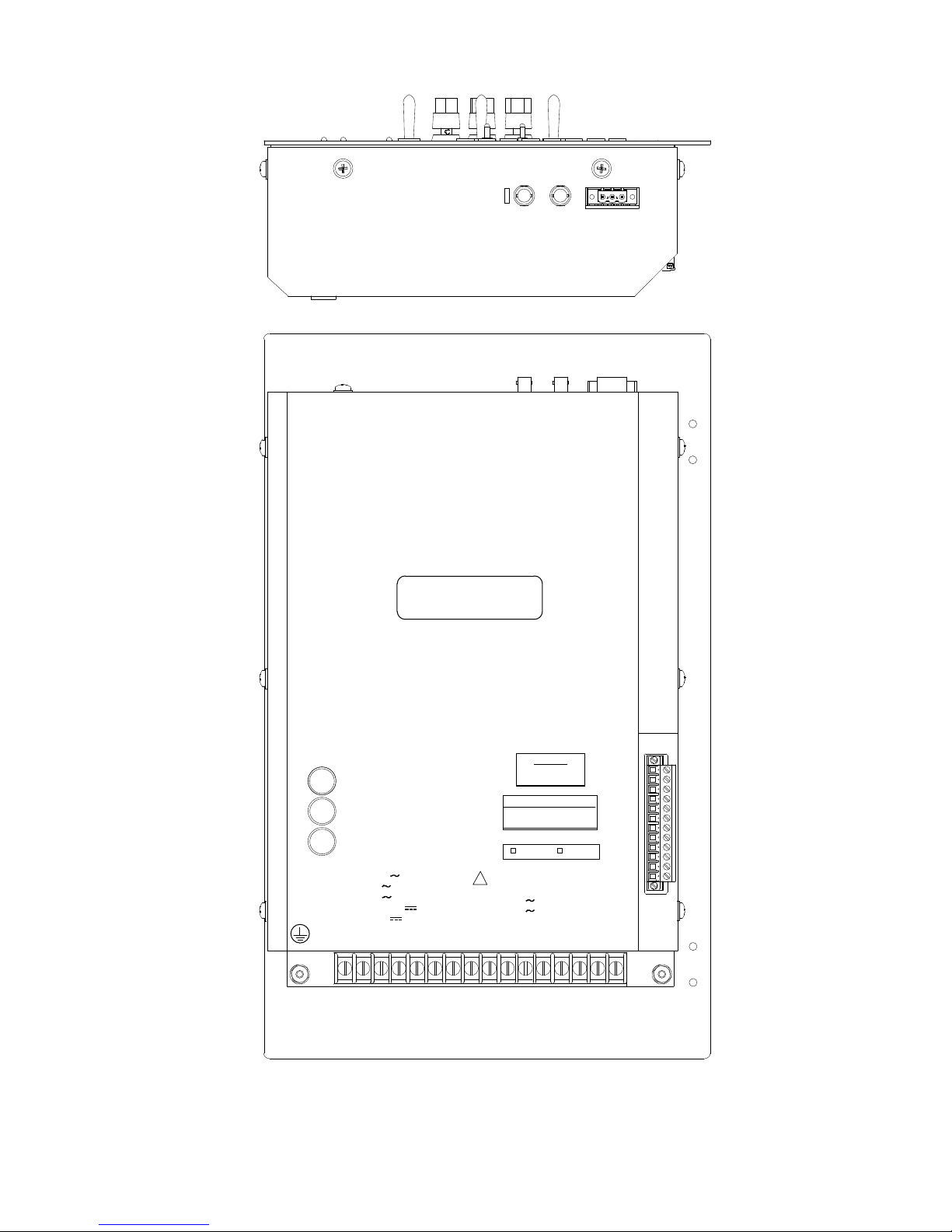
Layout of the M-6200A components are illustrated in Figure 2.
Do not position the M-6200A in a way that will make it difficult to operate the power disconnect
device.
The following is a brief summary of specifications that may be required for installation.
Voltage Withstand: 140 V continuous
240 V for one second
480 V for one cycle
Voltage measurement linear to 140 V
Current Withstand: Load Current:
0.48 amps continuous
4.0 amps for one second
Output Raise and Lower circuits:
6 amps AC
Alarm Contacts: Programmable Alarm/Selftest (Deadman)
6.0 amps AC, 125 V
0.2 amps DC, 125 V
B‑2355 Cooper
–1–
Page 9
M-6200A Application Guide
15.00
[12.5]
Smart Flash SD Card
S OU RC E
VO LTA G E
IN T
EX T
O FF
USB
RX
TX
9.18
[23.32]
0.65
[0.17]
1.10
[2.8]
1.0
[2.54]
9.77
[24.82]
1.0
[2.54]
3.22
[8.18]
0.88
[2.24]
OK
LOWER ALARM
EXTERNAL
POWER
METER
OUT
MANUAL
LOCAL
RAISE
REMOTE
LOCAL
SCADA
CUTOUT
DRAG HANDS
RESET
VOLTAGE
REDUCTION
REVERSE
POWER
COM
!
Made in U.S.A.
Digital Voltage Regulator Control
M-6200A
HTIWKCEB
CIRTCELE
.CNI.OC
EXIT
WAKE
VOLT
RED
ENT
UTIL
SETP
COMMMNTR
CNFG
MANUAL
AUTO
OFF
LOWER
RAISE
NEUTRAL
LIGHT
Figure 1 M-6200A Outline Dimensions
–2–
Page 10
TB1-8,10 90 -140 8 VA
TB1-5,6,9 240 6 A
TB2-6,7,8 120 6 A
TB1-1,2,4,7,11,16 12 0.100 A
TB2-11,12 10-16 5 W
TB2
RX
TX SH B A
1
TB1
1 16
2
3
4
5
6
7
8
9
10 11
12
13
14
15
FIBER
OPTIC
RS485
TB2
TB1-14, 15
+12
-11
BECKWITH ELECTRIC CO., INC.
6190-118th Avenue North - Largo,
Florida 33773-3724 U.S.A.
PHONE (727)544-2326 FAX (727)546-0121
www.beckwithelectric.com
OFF
ON
FIBER
REPEAT
MODEL: M-6200A-XXXXXXXXX
FIRMWARE: _______________
SERIAL # XXXXXX
VOLTAGE
TEST
MOTOR
POWER
0.5A 250V 3AG
GE, SIEMENS, HOWARD
CONNECT
TB2-2 TO TB2
-5
COOPER
CONNECT
TB2-1 TO TB2-2
50 Hz
60 Hz
0.48A CONTINUOUS
4.0A 1 SECOND
!
FIBER
REPEAT
SWITCH
3A 250V 3AG
6A 250V 3AG
B‑2355 Cooper
Figure 2 M-6200A Rear Layout
–3–
Page 11

M-6200A Application Guide
3.0 External Connections
Terminal Block Assignments
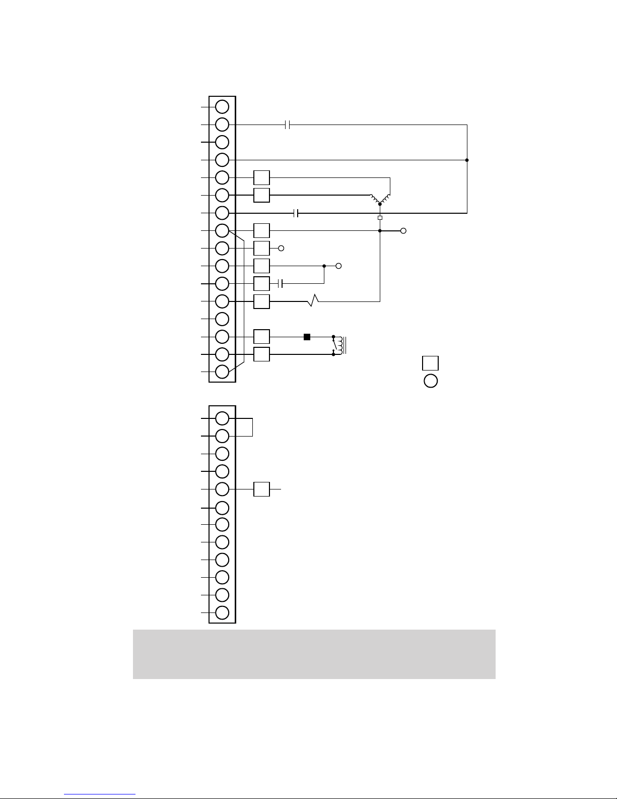
The external connections to the control are made to the two terminal blocks located on the
rear of the control, see Figure 3. See "Terminal Block Assignments" later in this section for
a description of each terminal assignment. For example, if external dry contacts are being
used to control the Voltage Reduction Step #1 function, connections for these contacts
may be made between TB1-4 and TB1-7 as shown in Figure 3. The dry contact inputs for
non-sequential input, voltage reduction must be "wetted" by connecting to terminal TB1-4.
See Table 1.
Typical Connections
Figure 3 illustrates typical connections for a regulator control. Motor Power and sensing
voltage can be obtained from a common source or from an independent source having a
nominal 120 Vac output. Normally, this is line-to-neutral voltage, although line-to-line voltage
can be used if recognition is made of any phase shift between the voltage and current signals
when using line drop compensation.
CAUTION:▲ The current input to the M-6200A is rated at 0.48 A continuous, and
4.0 A for 1 second.
Load current must be reduced by an appropriate auxiliary transformer to 0.2 A "full scale"
before connecting to the regulator current inputs.
Grounding
WARNING:8 The protective earth grounding terminal must be connected to
the installation earth ground anytime external connections have
been made to the unit.
Ground the control by connecting a 14 AWG, 300 V min., 105° C green insulated wire inserted
in an Amp 51864-8 or equivalent ring connector wire to the marked protective earth terminal
located adjacent to either side of TB1. Connect to the installation ground.
Unit Isolation
Sensing inputs should be equipped with test switches and shorting devices where necessary
to isolate the unit from external potential or current sources.
A switch or circuit breaker for the M-6200A's power shall be included in the building
installation, and shall be in close proximity to the control and within easy reach of the
operator, and shall be plainly marked as being the power disconnect device for the control.
Torque Requirements
Terminals TB1-1-16 & TB2-1-12: 7.5 in-lbs, minimum and 8.0 in-lbs, maximum.
Control Power Backup Input Connection
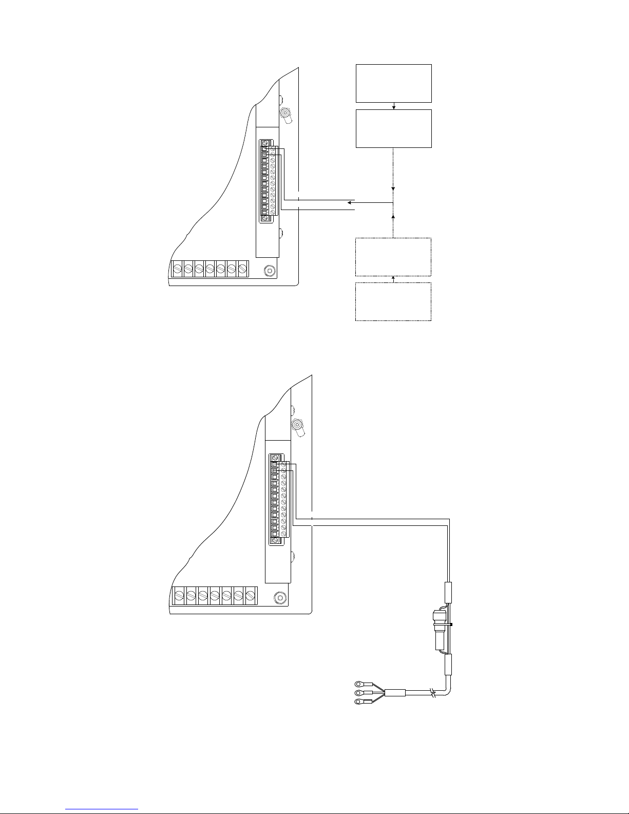
The Control Power Backup Input (Figure 4) is designed to sustain communication port
operation in the event of the loss of AC control power. In the event of a loss of AC input
power to the control, this feature permits uninterrupted operation of the control by supplying
+12 Vdc to the control. In addition, the control retains functionality with the exception of the
actual operation of the tapchanger mechanism.
When the AC input voltage drops below approximately 85 Vrms, the Control Power Backup
Input will activate and all automatic tapchange operations will then be suspended. If Motor
Power is available, manual tapchanges may be initiated.
When the control is being powered only by the backup DC input the Auto /Manual switch
status and the Local/Remote switch status are functional. When a control is being supplied
by both AC and DC via the backup power input and the backup DC input is lost the unit will
report it via DNP.
–4–
Page 12

B‑2355 Cooper
When the control is being powered from the Control Power Backup Input, it will continue to
read any input voltage present.
The control retains full functionality, and if the control's Motor Power remains energized
then Raise and Lower commands from SCADA are possible. Fiber-Optic port operation is
maintained. All communication ports, data-logging, status monitoring, configuration, and
setpoint capability are also maintained.
Beckwith Electric offers two Control Power Backup supplies for use with the M-6200A.
The M-2026 AC-DC Control Power Backup Supply is a fused, surge protected and reverse
polarity protected AC-DC Control Power Supply that accepts an AC or DC input (21 to 32,
42 to 60 and 105 to 145 V) and outputs regulated +12 Vdc at up to 1.5 Amp.
The M-2027 Control Power Backup Supply - AC Only is a fused and surge protected Control
Power Backup Supply that will accept an AC input range of 105 to 140 Vac, 50/60 Hz and
output +12 Vdc to 1 A.
Both the M-2026 and M-2027 are housed in non-weathertight enclosures and are equipped
with screw terminal blocks for both input and output connections.
Backup Power Requirements
The Control Power Backup Input that does not utilize the M-2026 or M-2027 should only be
used with the optional (B-0920) 3-Wire Harness. The harness (Figure 5), includes a 3 Amp
fast-blow fuse, and connects to TB2-11 (–) and TB2-12 (+) of the control.
CAUTION:▲ Use of Non-Beckwith Electric converters to provide +12 V to the
Control Power Backup Input may compromise system integrity due
to a lack of adequate protection of the power converter. For reliability
of the M-6200A, the power converter must meet the following
requirements:
Temperature: Operational from -40° C to + 85° C.
IEC 60068-2-1 Cold, -40° C
IEC 60068-2-2 Dry Heat, +80° C
IEC 60068-2-78 Damp Heat, +40° C @ 95%
IEC 60068-2-30 Damp Heat Condensing cycle 25° C, +55° C @ 95%
RH
RH
Surge Withstand Capability:
IEEE C37.90.1-2002 2,500 V pk Oscillatory
4,000 V pk Fast Transient Burst
IEEE C37.90.1-1989 2,500 V pk Oscillatory
5,000 V pk Fast Transient
Radiated Electromagnetic Withstand Capability:
All units are protected against electromagnetic radiated interference from portable
communications transceivers.
Electrostatic Discharge:
IEC 60255-22-2 (8 Kv) – Point Contact Discharge
IEC 60255-22-2 (15 Kv) – Air Discharge
Fast Transient/Burst Immunity:
IEC 60255-22-4-2008
Class A (4 Kv, 5 kHz)
–5–
Page 13
Position
Indicator Reset
Voltage In
(Reg 120 V)
Neutral
(Grd Stud)
(Motor Return)
Motor
L R
Voltage Reduction
Step #1 Contact
Voltage Reduction
Step #2 Contact
1
2
3
4
5
6
7
8
9
10
11
12
TB2
1
2
3
4
5
6
7
8
9
10
11
12
13
14
15
TB1
16
+12 Vdc Wetting Supply
Source Voltage
Load Current (+)
Load Voltage Input
Regulator Raise Output
Motor Power Input
Voltage Reduction Step #2 Input
Neutral Tap Position Input
Neutral
Regulator Lower Output
Non-Sequenti al Operatio n/Auto
Tapchange Inhibit Input
Voltage Reduction Step #1 Input
No Connection
Drag Hands Reset Output
Operations Counter Input(+)
Load Current (-)
Neutral Tap Position Input
Control Backup Power (-)
Control Backup Power (+)
Motor Seal-In
Alarm (NC)
Alarm Common
Alarm (NO)
No Connection
No Connection
No Connection
Neutral Light
Switch
CT
Line
Current
CT Shorting
Switch
M-6200A
VS
G
L3
R3
NL
DHR
C1
C3
Motor Power In
(Unregulated 120 V)
VM
HS
Motor Seal-In Inp ut
NOTE: Jumper wi re from TB1-8 to
TB1-16 is supplied with harness.
YY
M-6200A
Terminals
xx
Cooper Termi nals
Cooper
Configuration
Jumper
M-6200A Application Guide
WARNING:8 In no case should the line current circuit be interrupted with
the regulator or transformer energized. Do not remove auxiliary
current transformers without shorting the current inputs. Death
or severe electrical shock can occur.
Figure 3 Typical Connections for Cooper CL-2, CL-2A,
CL-4A, CL-4B, CL-4C, CL-5 and CL-6 Regulator Controls
–6–
Page 14
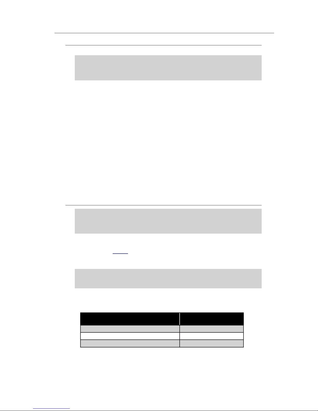
TERMINAL BLOCK ASSIGNMENTS (TB1)
TB1‑1 Non-Sequential Operation/Auto Tapchange Inhibit (or Aux 2)
Non-Sequential Operation
CAUTION:▲ Voltage applied through dry contacts to actuate non-sequential input
and voltage reduction inputs must be nominal +12 Vdc obtained from
TB1-4 of the M-6200A Regulator Control. The use of 120 Vac will
result in damage to the control.
The operation of the control can be interrupted during tapchanger operation by applying the
"wetting" voltage of TB1-4 to TB1-1 (timer reset for non-sequential operation input) on the
control through an external contact. This causes the output to de-energize and reinitialize
the time delay circuit when the reset signal is removed. This function can be used to cause
the Regulator, if so equipped, to wait for the unit to time out between tapchanges.
Non-sequential operation is invoked by momentarily connecting this input to the nominal
+12 Vdc wetting source (TB1-4) through an external Form "a" dry contact. When this function
is enabled, the tapchanger control times out with the Time Delay setting between every
tapchange.
Auto Tapchange Inhibit
Auto tapchange inhibit is invoked by closing and maintaining a Form "a" dry contact connected
to this input and to the nominal +12 Vdc wetting source (TB1-4). As long as this contact is
closed, the tapchanger will not time out, thereby prohibiting raise and lower commands.
Auxiliary Input (Aux 2)
To monitor the Battery Alarm Status, the optional Battery Pack sense line must be connected
to TB1-1 and the Non-Sequential input must be configured as "Aux 2".
B‑2355 Cooper
TB1‑2 Voltage Reduction Step #2 (or Aux)
TB1‑7 Voltage Reduction Step #1 (or Aux 1)
CAUTION:▲ Voltage applied through dry contacts to actuate non-sequential input
and voltage reduction inputs must be nominal +12 Vdc obtained from
TB1-4 of the M-6200A Regulator Control. The use of 120 Vac will
result in damage to the control.
On the M-6200A Digital Regulator Control, TB1-2 and TB1-7 are used together to provide
up to three levels of voltage reduction. The external connections to achieve these steps
are shown in this Table 1. Voltage reduction amounts are set within the M-6200A Digital
Regulator Control software. If these voltage reduction steps are instituted by communications,
the contacts are not being used simultaneously.
NOTE:Q Enabling both voltage reduction Step #1 and Step #2 inputs simultaneously
will result in the level of voltage reduction as specified on the voltage
reduction Step #3 screen of the control.
These digital inputs are typically enabled by connecting it to the nominal +12 Vdc wetting
source (TB1-4), through an external Form "a" dry contact. The amount of voltage reduction
implemented is determined by the setting.
Voltage Reduction Setpoint:
Multiplier Range
Voltage Reduction Setpoint #1: 0 to 10% TB1-7
Voltage Reduction Setpoint #2: 0 to 10% TB1-2
Voltage Reduction Setpoint #3: 0 to 10% TB1-7 and TB1-2
Apply "Wetting Voltage"
From TB1-4 to TB #
Table 1 Multi-Step Voltage Reduction External Connections
Auxiliary Input (Aux 1)
To monitor Intrusion Detection Status, the optional Intrusion Detection sense line must
be connected to TB1-7 and the Voltage Reduction 1 input must be configured as "Aux 1".
–7–
Page 15

M-6200A Application Guide
TB1‑3 No Connection or Source Voltage
TB1‑ 4 +12 Vdc Wetting Voltage
This is the output of an unregulated dc power supply internal to the control. It is referenced to
neutral and can supply up to 100 mA. It is used for powering the digital inputs of the control
through external dry contacts. Depending on the voltage supplied to TB1-10 and loading,
its output can vary from +10 to +18 Vdc. The output is current limited with a 1 ohm resister.
TB1‑5 Regulator Raise Output
This switched output connects the tapchanger raise winding to the source of motor power.
When the control calls for a raise, it is capable of switching up to 6 A at 120/240 Vac.
TB1‑ 6 Regulator Lower Output
This switched output connects the tapchanger lower winding to the source of motor power.
When the control calls for a lower, it is capable of switching up to 6 A at 120/240 Vac.
TB1‑ 8 Neutral
This is the return for the nominal +12 Vdc “wetting” voltage (TB1-4) and the voltage input
(TB1-10 ).
TB1‑9 Motor Power Input
The source for powering the tapchanger motor is connected here. It may have a maximum
voltage of 240 Vac.
TB1‑10 Load Voltage Input
This input accepts nominal 120 Vac, 60 Hz (or 50, Hz as ordered) to operate the control's
power supply and voltage sensing input. The acceptable voltage range for proper control
operation is from 90–140 Vac.
Power consumption is less than 8 VA. The input voltage is referenced to line neutral (TB1-8).
TB1‑11, TB1‑16 Neutral Tap Position Inputs
This digital input registers neutral position switch closures on regulators. The pins are
isolated from neutral to permit connection of the input based on regulator configuration.
TB1‑12 Drag Hands Reset
The drag hand reset output (TB1-12) connection is commonly used to reset the drag hand
on the regulator. When the Drag hand switch on the M-6200A is activated, this will cause
the unit to output 120 V to TB1-12. This voltage can be used to energize the drag hand
circuitry on the regulator.
TB1‑13 Operations Counter Input
This digital input registers the counter contact closure. The operations counter will increment
when TB1-13 is grounded by way of the regulator dry operation count switch. This contact is
needed for using the intertap time delay. Once a valid counter input is detected, the intertap
time delay will begin counting down.
–8–
Page 16

TB1‑14 Load Current (+)
CAUTION:▲ The current input to the M-6200A is rated at 0.48 A continuous, and
4.0 A for 1 second.
The line current input range is 0–640 mA (480 mA continuous) with 200 mA representing
the 1.0 per-unit value. The measured current value is used for line drop compensation and
metering calculation.
TB1‑15 Load Current (-)
This is the non-polarity input to the load current measuring transformer. The companion
polarity input is TB1-14. The line current transformer input is isolated from other pins.
TERMINAL BLOCK ASSIGNMENTS (TB2)
TB2‑1 Jumper TB2-1 to TB2-2 for Cooper regulators
TB2‑2 Jumper TB2-2 to TB2-5 for all regulators except Cooper
TB2‑3 Neutral Light Source
B‑2355 Cooper
TB2‑4 No Connection
TB2‑5 Motor Seal-in
Receives an Input from the Cooper Regulator Motor Cam Switch. Hardware Jumper TB2-2
to TB2-5 for all other regulators except Cooper.
TB2‑6, TB2‑7, TB2‑8 User Programmable Alarm
This set of terminals is a Form "C" alarm relay contact rated for 6 A at 120 Vac, or 100 mA at
120 Vdc. This alarm indicates when any of the programmable alarm conditions are detected.
Refer to the M-6200A Instruction Book.
TB2‑9, TB2‑10 No Connection
TB2‑11, TB2‑12 Control Power Backup Input
This input allows connection of external 12 Vdc control power backup power. The control
retains functionality with the exception of the actual operation of the tapchanger mechanism.
–9–
Page 17
M-6200A Application Guide
Facility AC-DC Source
21 - 32 V
42 - 60 V
105-145 V
M-2026 AC-DC Control
Power Backup Supply
Facility AC Source
105-140 Vac
M-2027 Control Power
Backup Supply AC
Only
+12 V
B-1021 Backup
Power Harness
TB2
10 11 12 13 14 15 16
1
2
3
4
5
6
7
8
9
10
11
12
Backup Power (-)
Backup Power (+)
3 Amp
Fast Blow Fuse
+12 V (White)
GND (BLK)
GND CHASSIS (DRAIN)
TB2
10 11 12 13 14 15 16
1
2
3
4
5
6
7
8
9
10
11
12
Backup Power (-)
Backup Power (+)
Figure 4 Typical Control Power Backup Connection for M-6200A
Utilizing M-2026 or M-2027 Supply
Figure 5 B-0920 Control Power Backup Input 3-Wire Harness
–10–
Page 18

4.0 Cooper CL‑2, CL‑2A, CL‑4A, CL‑4B, CL‑4C, CL‑5 and CL‑6
Regulator Controls Replacement
The Beckwith Electric M-6200A Digital Regulator control directly replaces Cooper CL-2,
CL-2A, CL-4A, CL-4B, CL-4C, CL-5 and CL-6 Regulator Controls.
The M-6200A may be purchased with the factory installed hardware kits:
• B-2355-C1 CL-2 through CL-5
• B-2355-C2 CL-6
• B-2355-C3 CL-2 through CL-5
• B-2355-C4 CL-6
The contents of the hardware kits provide the means to install the M-6200A in the existing
Cooper Regulator Control cabinet. The B-2355-C1, B-2355-C2, B-2355-C3, B-2355-C4
are available separately from the factory for field installation.
The difference between the B-2355-C1/B-2355-C3 and B-2355-C2/B-2355-C4 hardware
kits is the B-2355-C1/B-2355-C3 contains the harnesses for CL-2 through CL-5 control
replacement and the B-2355-C2/B-2355-C4 contain the harnesses for CL-6 control
replacement. The remaining kit contents are the same.
Application
Typical Connections
In general, the tapchanger motor must be operated from a different transformer than the
VT used to measure regulated voltage. If this is not done, hunting at the upper band edge
may result. As soon as the motor starts, and before it is sealed in, the motor current can
drop the voltage within the band and reset the control. Some motor seal-in schemes are
fast enough to prevent this, but others are not.
Pulsed output can be used on the M-6200A (see Instruction Book, Section 4.2 System
Setup, Output Pulse).
B‑2355 Cooper
External Connections
Power and voltage sensing are obtained either from a common source or from independent
sources having a nominal 120 Vac output. Normally, this is line-to-neutral voltage, although
line-to-line voltage can also be used if recognition is made of any phase shift between the
voltage and current signals when using line drop compensation.
The external connections for the M-6200A are made to terminal blocks TB1 and TB2 on the
rear of the control panel. The wiring harness and external connections for the M-6200A are
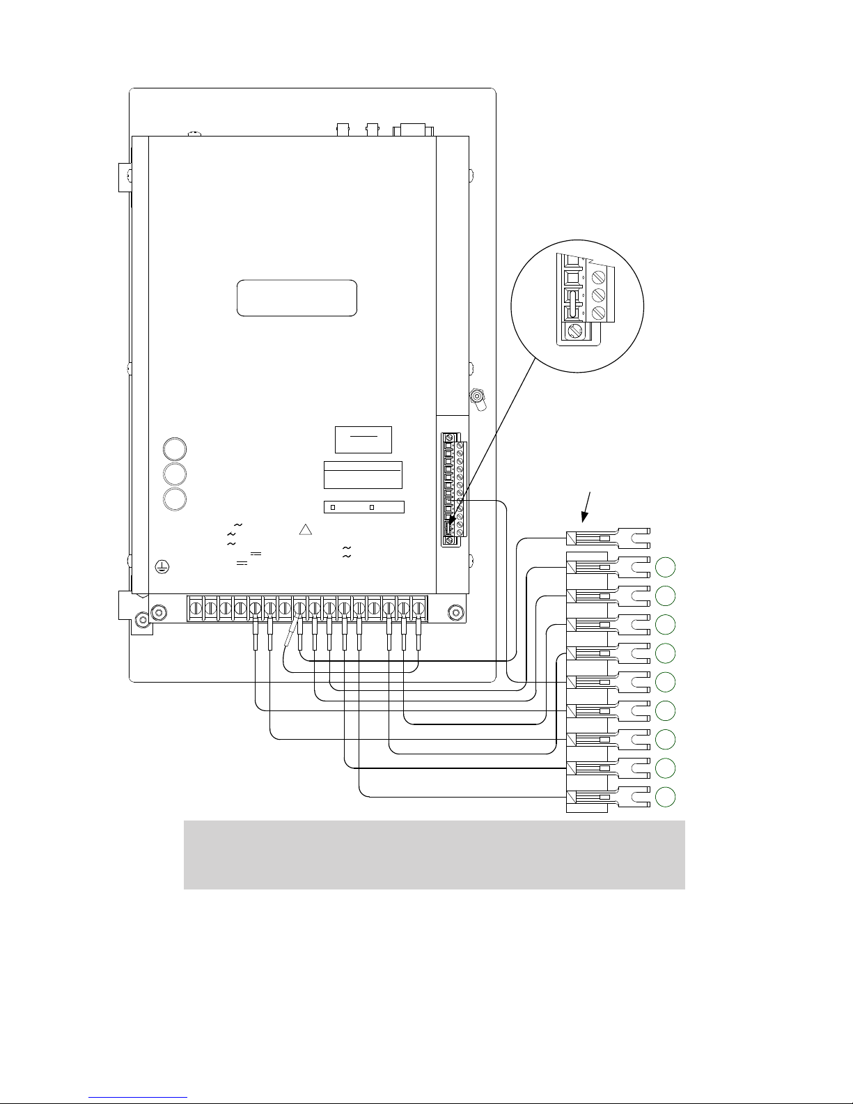
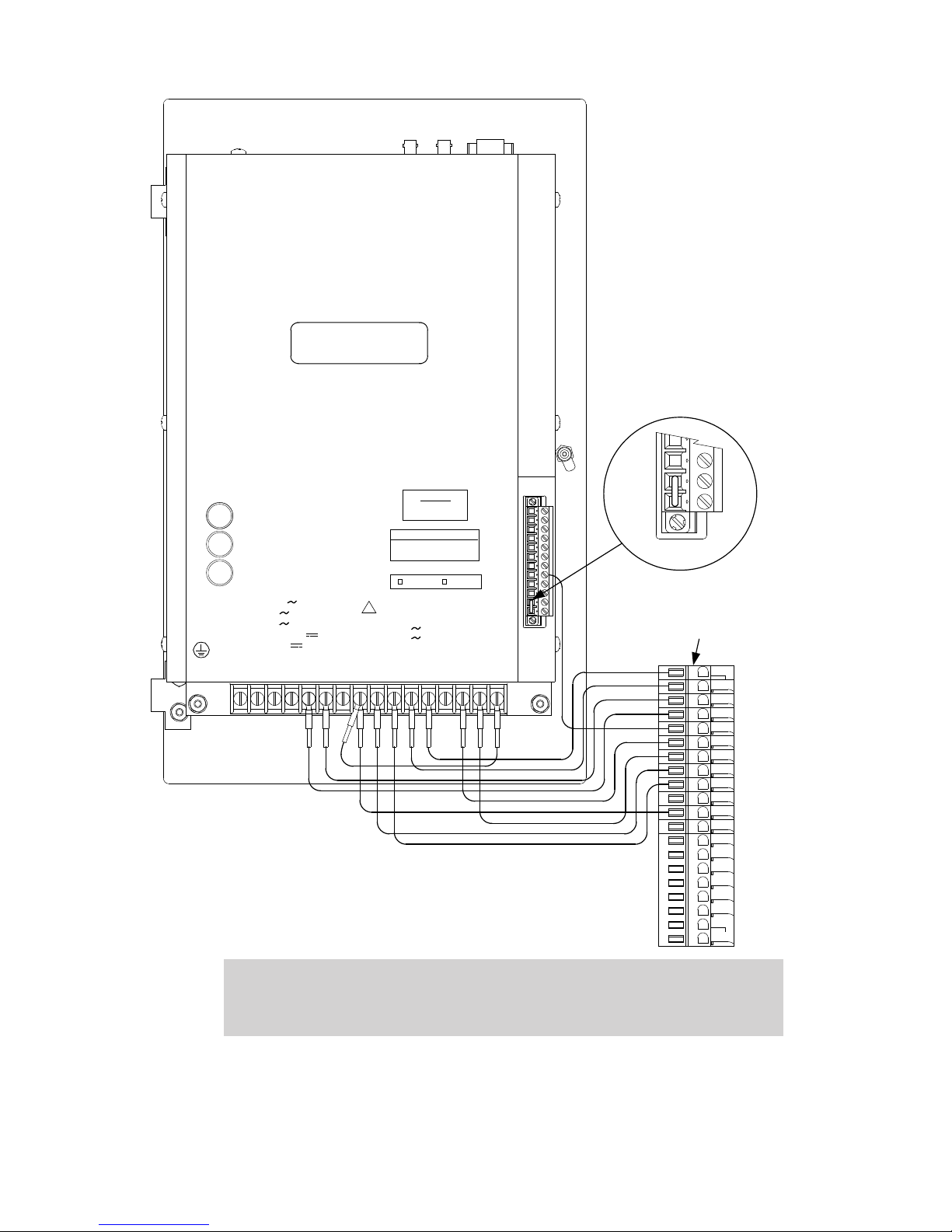
shown in Figure 8, Figure 9, Figure 10, and Figure 11.
Lightning Protection
CAUTION:▲ For proper protection against system surges, chassis ground must be
connected to earth ground.
It has been determined that transient voltages in excess of 1500 Vac RMS can exist on the
"ground" lead normally tied to TB1-8. In the regulator controls, these voltages are suppressed
by varistors which still permit the unit to pass a 1500 Vac hi-pot test for one minute, with a
leakage of approximately 15 mA, all terminals to ground.
Multiple VT grounds far apart must be avoided, since a varying difference in ground voltage
could add or subtract from the effective voltage, and cause variation in the tapchanger
control’s bandcenter voltage setpoint.
Non-Sequential Operation/ Counter Input
Not normally used with Cooper Regulators.
–11–
Page 19

M-6200A Application Guide
Multi-Step Voltage Reduction
CAUTION:▲ Voltage applied through dry contacts to actuate Voltage Reduction
The M-6200A uses terminals TB1-2 and TB1-7 together to provide up to three levels of
voltage reduction. The external connections to achieve these steps are shown in Table 1
and Figure 3. Voltage reduction amounts are set in the M-6200A Regulator Control software.
Removal of the Cooper Control
WARNING:8 In no case should the line current circuit be interrupted with
1. Verify that the regulator control wiring is in a safe condition that will allow removal
of the Cooper Regulator Control from the control cabinet.
• The control wiring is de-energized and isolated from any potential safety
hazards.
• All local Safety Tagging rules have been applied as necessary.
2. Open the cabinet door of Cooper control.
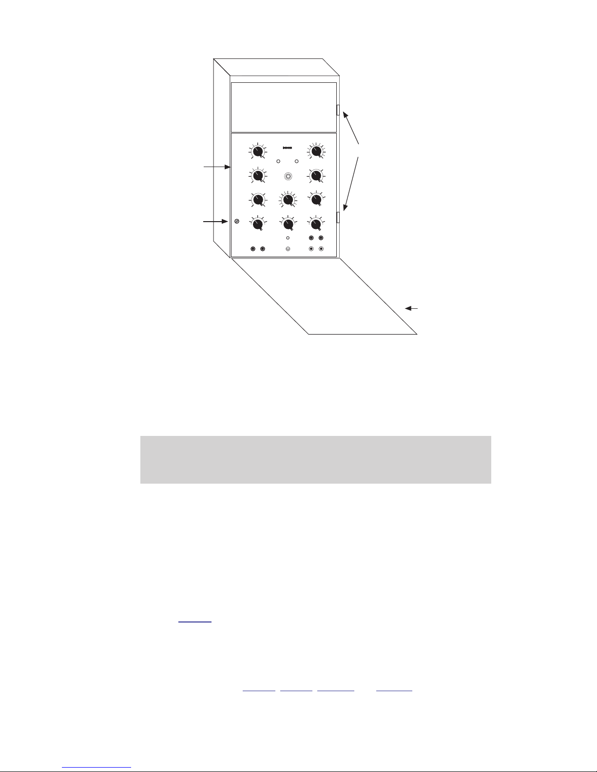
3. Loosen the thumb screws on the control panel (Figure 6), and swing the panel
outward.
WARNING:8 In no case should the line current circuit be interrupted with
Steps 1, 2, and 3 must be +12 Vdc obtained from terminal TB1-4 of
the M-6200A Regulator Control.
the regulator or transformer energized. Do not remove auxiliary
current transformers without shorting the current inputs. Death
or severe electrical shock can occur.
the regulator or transformer energized. Do not remove auxiliary
current transformers without shorting the current inputs. Death
or severe electrical shock can occur.
4. De-energize the control by opening the VT disconnect switch and placing the
CT switch in the shorting position. Ensure that the CT in the regulator has been
properly shorted.
5. Loosen the screws on the spreader bar terminal block at the bottom of the cabinet,
then pull down on the spreader bar to disconnect it.
NOTE:Q The two hinge pins must be saved from the original control.
6. Remove and save the two hinge pins, then lift the panel off of the hinges and
remove it from the cabinet.
–12–
Page 20
Control
Control
Panel
Knob
→
Hinge Pins
McGRAW-EDISON
Panel
➀
B‑2355 Cooper
Cabinet Door
Figure 6 Cooper Control in Cabinet
Installing the M-6200A in a Cooper Regulator
The hinge leaves and latch bracket mechanism are oriented to match the existing hinge
leaves and latch of the Cooper control cabinet.
If Bench Testing of the M-6200A is required, then refer to Instruction Book, Chapter 7,
Testing.
WARNING:8 In no case should the line current circuit be interrupted with
the regulator or transformer energized. Do not remove auxiliary
current transformers without shorting the current inputs. Death
or severe electrical shock can occur.
1. Verify that the applicable B-2355-C1, B-2355-C2, B-2355-C3 or B-2355-C4
hardware kit has been installed on the the control.
If the applicable hardware kit is not installed, then proceed to the appropriate
hardware kit configuration section to install the hardware kit.
2. Verify that the regulator control wiring is in a safe condition that will allow installation
of the M-6200A in the control cabinet.
• The control wiring is de-energized and isolated from any potential safety
hazards.
• All local Safety Tagging rules have been applied as necessary.
3. Mount the M-6200A Regulator Control onto the hinges in the control cabinet
(Figure 6), then install the two hinge pins saved from the original control. Leave
the panel in the open position so that the back of the panel is accessible.
4. If the frame that the latch bracket is mounted to requires the use of longer panel
thumbscrews, then replace the two panel thumbscrews with the longer versions
provided in the cloth bag.
5. Connect the M-6200A’s wiring harness to the terminal block at the bottom of the
cabinet. Refer to Figure 8, Figure 9, Figure 10, and Figure 11.
6. Set the toggle switch to the Manual position.
–13–
Page 21
M-6200A Application Guide
7. To re-energize the control perform the following:
a. Open the CT switch, removing the CT shorting circuit.
b. Close the VT disconnect switch.
c. Swing the adapter panel closed and turn thumbscrews to latch securely.
8. Set up the desired configuration. See Instruction Book, Chapter 4, System
Setup and Configuration.
9. Refer to Instruction Book, Chapter 7, Testing for testing requirements.
B-2355-C1/B-2355-C2 Hardware Kit Configuration
1. If the M-6200A to be configured has existing mounting hardware installed, then
perform the following:
a. Remove all hinges, latches, brackets, wiring harnesses and jumpers.
b. Save/capture all removed hardware for future use.
2. Verify the ontents of the B-2355-C1/B-2355-C2 Hardware Kit includes the items
in Table 2:
Qty Description Beco Part #
1 Top Hinge Half-Female P2393 440-40923
1 Bottom Hinge Half-Female P2373 440-40913
1 Bracket P-2372 Panel Adaptor 441-41323
6 Screw, Fillister, 8-32 x 7/16 470-00830
1 Wire Harness, B-2355 (B-2355-1) B-1128 (B-1157)
2 Fast Lead Screw 441-00385
2 Fastener, Screw, Retainer 440-00855
2 U-Clip 441-00386
Table 2 B-2355-C1 and B-2355-C2 Hardware Kit
3. Remove pre-cut label material from the four right side hinge mounting holes and
the first and fourth (from top) left side hinge mounting holes as viewed from the
front of the M-6200A panel.
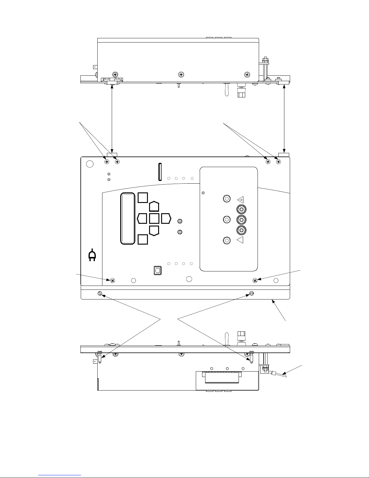
NOTE:Q Refer to Figure 7 for location and orientation of hardware kit items.
4. Mount the Bottom Hinge to the lower right side of the M-6200A, then secure (hand
tight) the hinge utilizing an 8-32 X 7/16 screw inserted into the captured fastener
in the top hole.
5. Complete the Bottom Hinge installation with an 8-32 X 7/16 screw inserted into the
captured fastener in the bottom hole, then tighten the top screw.
6. Mount the Top Hinge to the upper right side of the M-6200A panel utilizing 8-32 X 7/16
screws inserted into the captured fasteners.
7. Mount the Latch Bracket to the left side of the M-6200A panel utilizing 8-32 X 7/16
screws inserted into the captured fasteners in the first and fourth hinge holes from
the top.
8. Connect the applicable wiring harness B-1128 for B-2355-C1 or B-1157 for
B-2355-C2 to TB1 and TB2 Terminal Blocks as indicated in Figures 8 or 9. See
terminal block torque requirements in Section 3.0, External Connections.
Verify that a jumper is installed between TB2-1 and TB2-2.
9. Proceed to the M-6200A Installation procedure in this section.
–14–
Page 22
B‑2355 Cooper
POWER
EXTERNAL METER
M-6200A
SO URCE
VOLTAG E
INT
EX T
OFF
RAIS E
LOWE R
NEUT
RAL
BECKWITH
ELECTRIC
CO. INC.
OUT
COM
OFF
MANUA L
AUTO
RXTX
LIGHT
Ma de in U.S .A .
Digital Voltage Regulator Control
Top Hinge Half, P-2393,
Female, Part # 440-40923
Screw, Fillister, 8-32 X 7/16
Part # 470-00830
Fastener, Screw,
Retainer
Part # 440-00855
Screw, Fillister, 8-32 X 7/16
Part # 440-00830
Bottom Hinge Half, P-2373,
Female, Part # 440-40913
Wire Harness
Screw, Fillister, 8-32 X 7/16
Part # 470-00830
Screw, Fillister, 8-32 X 7/16
Part # 440-00830
Bracket, P-2372,
Panel Adap
Part # 441-41323
!
Smart Flash SD Card
USB
OK
LOWER ALARM
MANUAL
LOCAL
RAISE
REMO TE
LOCAL
SCADA
CUTOUT
DRAG
HANDS
RESET
VOLTAGE
REDUCTION
REVERSE
POWER
EXIT
WAKE
VOLT
RED
ENT
UTIL
SETP
COMM
MNTR
CNFG
Figure 7 B-2355-C1/B-2355-C2, B-2355-C3/B-2355-C4 Hardware Kit Orientation
–15–
Page 23
M-6200A Application Guide
Cooper Control Cabinet Terminals
TB1-8 G Ground
TB1-10 VS Voltage Sense (120 Vac) (Note 1)
TB1-9 VM Motor Supply 120 Vac (Note 2)
TB1-15 C1 Load Current Return
TB1-14 C3 Load Current Polarity
TB1-16 G Neutral Light Common
TB1-5 R3 Raise Limit Switch
TB1-6 L3 Lower Limit Switch
TB1-11 NL Neutral Light
TB1-12 DHR Drag Hands Reset
TB2-5 HS Motor Seal-In Input
Notes:
1. Regulated voltage for load-side sense without Reverse
Power Flow Option.
2. Regulated voltage for load-side sense with Reverse
Power Flow Option.
1 16234
5
6
7 8910 11 121314
15
TB2-1
TB2-2
TB2
Jumper TB2-1 to TB2-2.
Harness/Fanning Strip B-1128 for CL-2,
CL-2A, CL-4A, CL-4B, CL-4C and CL-5
Regulator Control Replacement.
8
6
5
4
2
3
7
8
6
5
4
2
3
7
9
1
E-1
VS
DHR
L3
C1
VM
C3
HS
R3
NL
TB1-8,10 90-140 8 VA
TB1-5,6,9 240 6A
TB2-6,7,8 120 6A
TB1-1,2,4,7,11,16 12 0 .100A
TB2-11,12 10-16 5 W
TB2
R
X
TX SH B A
1
TB1
FIBER
OPTIC
RS485
TB2
TB1-14, 15
+12
-11
BECKWITH ELECTR IC CO., INC.
6190-118th Avenue North - Largo, Florida 33773-3724 U.S.A.
PHON E (727)544-2326 FAX (727)546-0121
www.beckwithelectric.com
MODEL : M-6200A-XXXXXXXXX
FIRMWARE: _______________
SERIAL # XXXXXX
VOLT AGE
TEST
MOTOR
POWER
0.5A 250V 3AG
GE, SIEM ENS, HOWARD
CONNECT
TB2-2 TO TB2-5
COOPER
CONNECT
TB2-1 TO TB2-2
50 Hz 60 Hz
0.48A CONTINUOUS
4.0A 1 SECOND
!
FIBER
REPEAT
SWITC H
3A 250V 3AG
6A 250V 3AG
Figure 8 M-6200A (B-1128) Cooper Wiring Harness (Fanning Strip) for CL-2 through
WARNING:8 In no case should the line current circuit be interrupted with
the regulator or transformer energized. Do not remove auxiliary
current transformers without shorting the current inputs. Death
or severe electrical shock can occur.
CL-5Regulators
–16–
Page 24
B‑2355 Cooper
Cooper Control Cabinet Terminals
TB1-8 G Ground
TB1-10 VS Voltage Sense (120 Vac) (Note 1)
TB1-9 VM Motor Supply 120 Vac (Note 2)
TB1-15 C1 Load Current Return
TB1-14 C3 Load Current Polarity
TB1-16 G Neutral Light Common
TB1-5 R3 Raise Limit Switch
TB1-6 L3 Lower Limit Switch
TB1-11 NL Neutral Light
TB1-12 DHR Drag Hands Reset
TB2-5 HS Motor Seal-In Input
Notes:
1. Regulated voltage for load-side sense without Reverse
Power Flow Option.
2. Regulated voltage for load-side sense with Reverse
Power Flow Option.
1 162 3 4
5
6
7 8910 11 12 13 14
15
Jumper TB2-1 to TB2-2.
TB2-1
TB2-2
TB2
Neutral
Load Voltage
Drag Hands Reset
Lower
Raise
Seal-In
Neutral Light +
Load Current polarity
Load Current return
Motor Supply
P-1
Harness/Gray Plug B-1157 for CL-6
Regulator Control Replacement
1 2 3 4 5 6 7 8 9 10 11 12 13 14 15 16 17 18 19 20
TB1-8,10 90-140 8VA
TB1-5,6,9 240 6A
TB2-6,7,8 120 6A
TB1-1,2,4,7,11,16 12 0 .100A
TB2-11,12 10-16 5W
TB2
R
X
TX SH B A
1
TB1
FIB ER
OPTIC
RS485
TB2
TB1-14, 15
+12
-11
BECKWIT H ELECT RIC CO., INC.
6190-118th Avenue North - Largo, Florida 33773-3724 U.S.A.
PHONE (727)544-2326 FAX (727)546-0121
www.beckwithelectric.com
MODEL : M-6200A-XXXXXXXXX
FIR MWARE: _______________
SERIAL # XXXXX X
VOLTA GE
TEST
MOTOR
POWER
0.5A 250V 3AG
GE, SIEMEN S, HOWARD
CONNECT
TB2-2 TO TB 2-5
COOPER
CONNECT
TB2-1 TO TB 2-2
50 Hz 60 Hz
0.48A CONTINUOUS
4.0A 1 SECOND
!
FIBER
REPEAT
SWITCH
3A 250V 3AG
6A 250V 3AG
WARNING:8 In no case should the line current circuit be interrupted with
Figure 9 M-6200A (B-1157) Cooper Wiring Harness (Gray Plug) for CL-6 Regulators
the regulator or transformer energized. Do not remove auxiliary
current transformers without shorting the current inputs. Death
or severe electrical shock can occur.
–17–
Page 25
M-6200A Application Guide
B-2355-C3/B-2355-C4 Hardware Kit Configuration
1. If the M-6200A to be configured has existing mounting hardware installed, then
perform the following:
a. Remove all hinges, latches, brackets, wiring harnesses and jumpers.
b. Save/capture all removed hardware for future use.
2. Verify the contents of the B-2355-C3/B-2355-C4 Hardware Kit includes the items
in Table 3:
Qty Description Beco Part #
1 Top Hinge Half-Female P2393 440-40923
1 Bottom Hinge Half-Female P2373 440-40913
1 Bracket P-2372 Panel Adap 441-41323
6 Screw, Fillister, 8-32 x 7/16 470-00830
1 Wire Harness, B-2355 (B-2355-1) B-1259 (B-1260)
2 Fast Lead Screw 441-00385
2 Fastener, Screw, Retainer 440-00855
2 U-Clip 441-00386
Table 3 B-2355-C3 and B-2355-C4 Hardware Kit
3. Remove pre-cut label material from the four right side hinge mounting holes and
the first and fourth (from top) left side hinge mounting holes as viewed from the
front of the M-6200A panel.
NOTE:Q Refer to Figure 7 for location and orientation of hardware kit items.
4. Mount the Bottom Hinge to the lower right side of the M-6200A, then secure (hand
tight) the hinge utilizing an 8-32 X 7/16 screw inserted into the captured fastener
in the top hole.
5. Complete the Bottom Hinge installation with an 8-32 X 7/16 screw inserted into the
captured fastener in the bottom hole, then tighten the top screw.
6. Mount the Top Hinge to the upper right side of the M-6200A panel utilizing 8-32 X 7/16
screws inserted into the captured fasteners.
7. Mount the Latch Bracket to the left side of the M-6200A panel utilizing 8-32 X 7/16
screws inserted into the captured fasteners in the first and fourth hinge holes from
the top.
8. Determine if the control is equipped with a B-1255 Universal Wiring Harness and
proceed as follows:
a. If the control has a B-1255 Universal Wiring Harness installed on TB1 and
TB2, then go to Step 9.
b. If the control does not have a B-1255 Universal Wiring Harness installed on
TB1 and TB2, then connect the B-1255 harness to TB1 and TB2 as indicated
in Figures 10 or 11 (See terminal block torque requirements in Section 3.0,
External Connections). Go to Step 9.
9. Connect the applicable wiring harness B-1259 for B-2355-C3 or B-1260 for
B-2355-C4 to the P-5 and P-6 connectors.
Verify that a jumper is installed between TB2-1 and TB2-2.
10. Proceed to the M-6200A Installation procedure.
–18–
Page 26
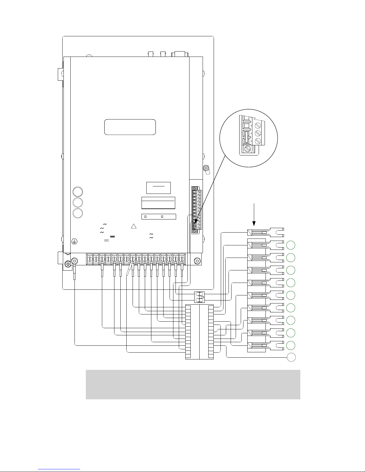
1 16
2 3
4
5
6
7 8910 11
12 13
14
15
Cooper Control Cabinet Terminals
TB1-8 G Ground
TB1-10 VS Voltage Sense (120 Vac) (Note 1)
TB1-9 VM Motor Supply 120 Vac (Note 2)
TB1-15 C1 Load Current Return
TB1-14 C3 Load Current Polarity
TB1-16 G Neutral Light Common
TB1-5 R3 Raise Limit Switch
TB1-6 L3 Lower Limit Switch
TB1-11 NL Neutral Light
TB1-12 DHR Drag Hands Reset
TB2-5 HS Moto r Seal-In Input
Notes:
1. Regulated voltage for load-side sense without Reverse
Power Flow Option.
2. Regulated voltage for load-side sense with Reverse
Power Flow Option.
Jumper TB2-1 to TB2-2.
TB2-1
TB2-2
TB2
P6
J6
P5
J5
2
2
1
1
3
3
4
4
5
5
6
6
7
7
8
8
9
9
10
10
11
11
12
12
13
13
14
14
15
15
2
2
1
1
Harness B-1255
Harness B-1259
Harness/Fanning Strip B-1259 for CL-2,
CL-2A, CL-4A, CL-4B, CL-4C and CL-5
Regulator Control Replacement.
8
6
5
4
2
3
7
8
6
5
4
2
3
7
9
1
E-1
VS
DHR
L3
C1
VM
C3
HS
R3
NL
GND
PANEL
GROUND
TB1-8,10 90-140 8VA
TB1-5,6,9 240 6A
TB2-6,7,8 120 6A
TB1-1,2,4,7,11,16 12 0.100A
TB2-11,12 10-16 5W
TB2
R
X
TX SH B A
1
TB1
FIB ER
OPTIC
RS485
TB2
TB1-14, 15
+12
-11
BECKWITH ELECTRIC CO., INC.
6190-118th Avenue North - Largo, Florid a 33773-3724 U.S.A.
PHONE (727)544-2326 FAX (727)546-0121
www.beckwithelectric.com
MODEL : M-6200A-XXXXXXXXX
FIRMWARE: __ _____________
SERIAL # XXXXXX
VOLT AGE
TEST
MOTOR
POWER
0.5A 250V 3AG
GE, SIEM ENS, HOWARD
CONNECT
TB2-2 TO TB 2-5
COOPER
CONNECT
TB2-1 TO TB 2-2
50 Hz
60 Hz
0.48A CONTINUOUS
4.0A 1 SECOND
!
FIB ER
REPEAT
SWIT CH
3A 250V 3AG
6A 250V 3AG
B‑2355 Cooper
WARNING:8 In no case should the line current circuit be interrupted with
Figure 10 B-2355-C3 (B-1255 and B-1259) Cooper Wiring Harness
the regulator or transformer energized. Do not remove auxiliary
current transformers without shorting the current inputs. Death
or severe electrical shock can occur.
–19–
Page 27
M-6200A Application Guide
1 16
2 3
4
5
6
7 8910
11
12 13
14
15
P6
J6
P5
J5
2 2
1 1
3 3
4 4
5 5
6 6
7 7
8 8
9 9
10 10
11 11
12 12
13
13
14
14
15
15
2 2
1 1
Harness B-1255
Harness B-1260
GND
Neutral
Load Voltage
Drag Hands Reset
Lower
Raise
Seal-In
Neutral Light +
Ground
Load Current polarity
Load Current return
Motor Supply
G
VS
VM
P-1
C1
C3
HS
R3
L3
NL
DHR
Cooper Control Cabinet Terminals
TB1-8 G Ground
TB1-10 VS Vol tage Sense (120 Vac) (Note 1)
TB1-9 VM Motor Supply 120 Vac (Note 2)
TB1-15 C1 Load Current Return
TB1-14 C3 Load Current Polarity
TB1-16 G Neutral Light Common
TB1-5 R 3 Raise Limit Switch
TB1-6 L3 Lower Limit Switch
TB1-11 NL Neutral Light
TB1-12 DHR Dr ag Hands Reset
TB2-5 HS Motor Seal-In Input
Notes:
1. Regulated voltage for load-side sense without Reverse
Power Flow Option.
2. Regulated voltage for load-side sense with Reverse
Power Flow Option.
Jumper TB2-1 to TB2-2.
TB2-1
TB2-2
TB2
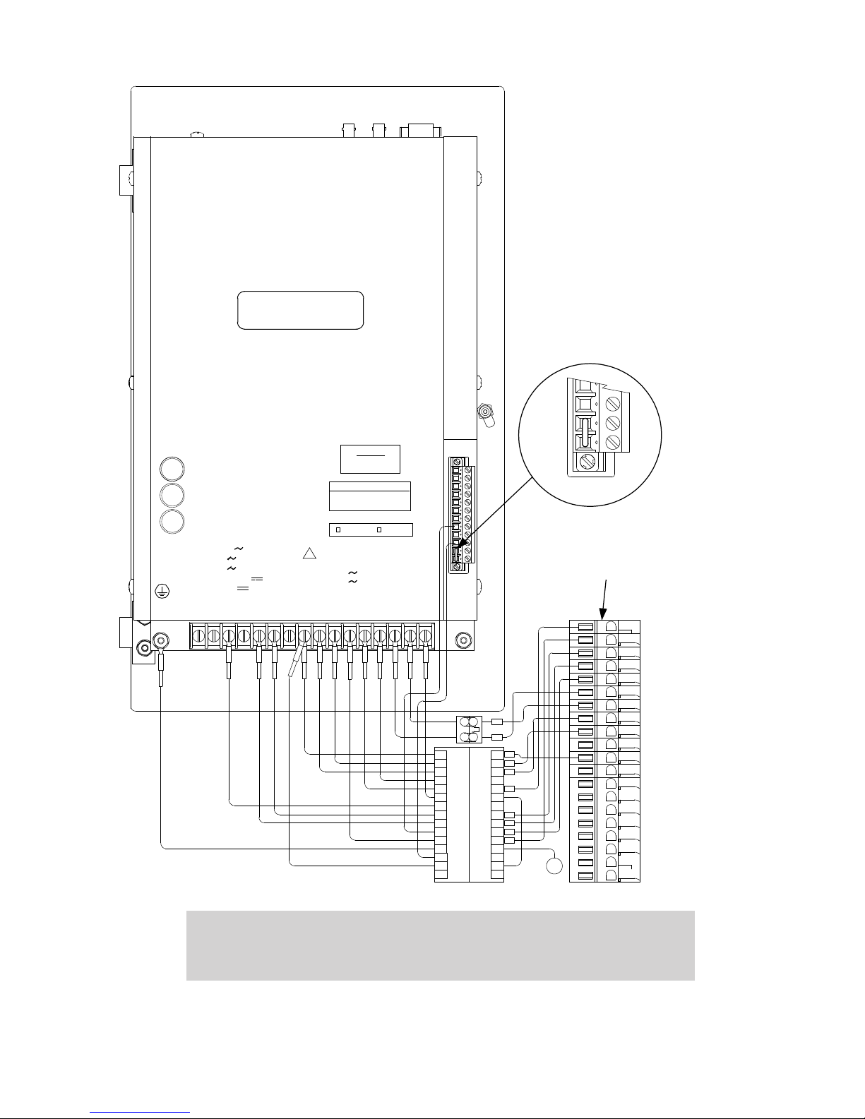
Harness/Gray Plug B-1260 for CL-6
Regulator Control Replacement
1 2 3 4 5 6 7 8 9 10 11 12 13 14 15 16 17 18 19 20
TB1-8,10 90-140 8VA
TB1-5,6,9 240 6A
TB2-6,7,8 120 6A
TB1-1,2,4,7,11,16 12 0.100A
TB2-11,12 10-16 5W
TB2
R
X
TX SH B A
1
TB1
FI
BER
OPTIC
RS485
TB2
TB1-14, 15
+12
-11
BECKWITH ELECTRIC CO., INC.
6190-118th Avenue North - Largo, F lor ida 33773-3724 U.S.A.
PHONE (727)544-2326 FAX (727)546-0121
www.beckwith electr ic.com
MODEL : M-6200A-XXXXXXXXX
FIRMWARE: _______________
SERIAL # XX XXXX
VOLTA GE
TEST
MOTOR
POWER
0.5A 250V 3AG
GE, SIEM ENS, HOW ARD
CONNECT
TB2-2 TO TB2-5
COOPER
CONNECT
TB2-1 TO TB2-2
50 Hz
60 Hz
0.48A CONTINUOUS
4.0A 1 SECON D
!
FIB ER
REPEAT
SWITC H
3A 250V 3AG
6A 250V 3AG
WARNING:8 In no case should the line current circuit be interrupted with
the regulator or transformer energized. Do not remove auxiliary
current transformers without shorting the current inputs. Death
or severe electrical shock can occur.
Figure 11 B-2355-C4 (B-1255 and B-1260) Cooper Wiring Harness
–20–
Page 28

5.0 TapTalk S‑6200 Communications Software Installation
The TapTalk S-6200 installation program has been written to overwrite previous versions
of TapTalk. However, considering variations in installed software, hardware and operating
systems, if you are upgrading from a previous version of TapTalk, it is recommended that
any older versions of the TapTalk program be removed before installing the new TapTalk.
TapTalk runs with the Microsoft Windows 2000, XP, Vista or Windows 7 operating system.
Familiarity with Windows is important in using TapTalk, as the conventions defined in the
Windows documentation are strictly followed.
TapTalk will be installed on the host PC’s hard disk. While it does not require special
installation procedures, an installation utility has been provided to make the process easier.
To install TapTalk:
1. Insert the TapTalk software into your CD-ROM drive.
2. Select Run from the Start Menu.
3. In the Run dialog box, initiate software installation by typing D:\Setup.exe (or
other drive designator:\Setup.exe, depending on the letter designation for the
CD-ROM drive).
4. The Installation Wizard will prompt the user through the installation process. After
installation, the TapTalk program icon (located in the Becoware folder) can be
placed on the desktop (Figure 12).
B‑2355 Cooper
Starting Ta pTa lk
1. Select the TapTalk program-item icon from the Becoware group in the Program
Manager, or select TapTalk from the program list using the Start Menu. The TapTalk
Main Screen will be displayed.
Figure 12 S-6200 TapTalk Program-Item Icon
6.0 Activating Initial Local Communications
The M-6200A and TapTalk S-6200 Communications Software are shipped from the factory
with the same default communication parameters. Therefore, it may not be necessary to
setup communication parameters.
To use TapTalk to interrogate, set, or monitor the M-6200A Digital Regulator Control using
a direct USB connection, the appropriate driver must be loaded. The driver that is required
to be resident in the "windows\inf" folder on the host PC is "beco_usb.inf". The driver is
automatically loaded by the TapTalk installation software.
When the control is connected to the PC utilizing a USB cable, Windows will enumerate the
control as a serial com device and will assign an unused COM Port to the control.
Refer to Appendix A, Figure A-4, Communication Menu Flow Screens and Instruction
Book, Secti o n 4.1, System Setup, for additional setup information.
Activating Initial Communication using USB (Serial) Connection and Default Communication
parameters is accomplished as follows:
1. Ensure the following conditions exist:
• TapTalk is installed on the host computer
• The control is energized
2. Plug the USB cable into the host PC USB port.
–21–
Page 29
M-6200A Application Guide
3. Plug the USB cable into the USB port on the control. The host PC will:
a. Interrogate the control to determine the type of hardware device it is.
NOTE:Q If the host PC cannot identify the proper driver for the M-6200A, the driver
can be found on the TapTalk software installation disk.
b. Load any required drivers.
c. Assign the next available COM port to the USB connection.
4. Start the TapTalk program, TapTalk will display the TapTalk Main dialog screen.
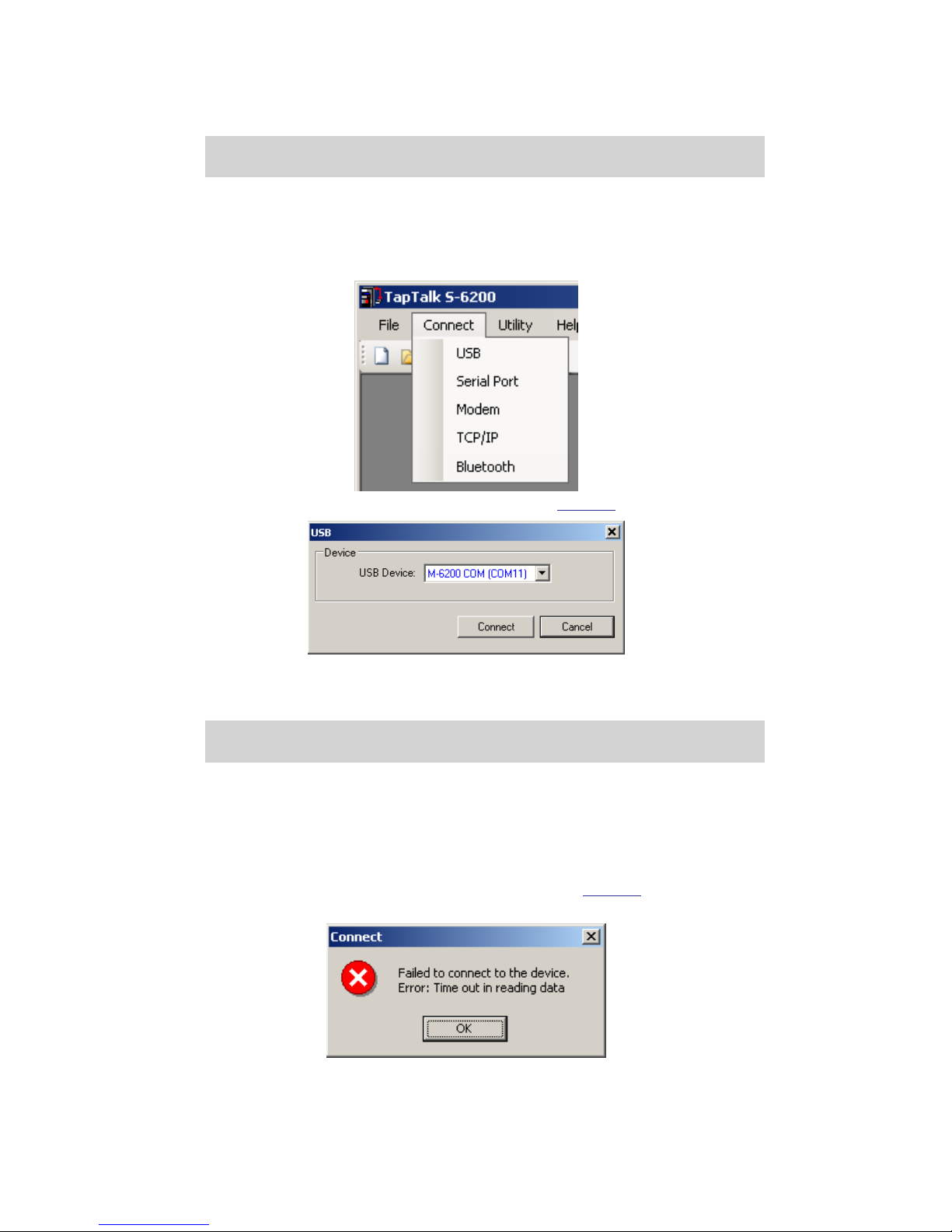
5. Select Connect/USB from the Connect drop-down menu.
TapTalk will display the USB Port dialog screen (Figure 13).
Figure 13 USB Port Connection Dialog Screen
6. Ensure that the correct COM port is displayed for the selected USB device.
NOTE:Q TapTalk will automatically choose the port for the control you just connected
to.
7. Enter "Access Level Code" and check "Save" if desired.
Default Values:
Level 1 000000 (Disabled)
Level 2 222222
8. Select Connect, TapTalk will attempt to connect to the target control.
9. If TapTalk returns a Failed to Connect Error screen (Figure 14), then repeat Steps
6, 7 and 8.
Figure 14 Failed to Connect Error Screen
–22–
Page 30
B‑2355 Cooper
10. If Level 1 Access is not active or the proper Level 1 or Level 2 access code was
entered, then TapTalk will briefly display a "Successfully Connected Level 1/Level
2" confirmation screen, then display the connected version of the TapTalk Main
Screen with the appropriate Access Level.
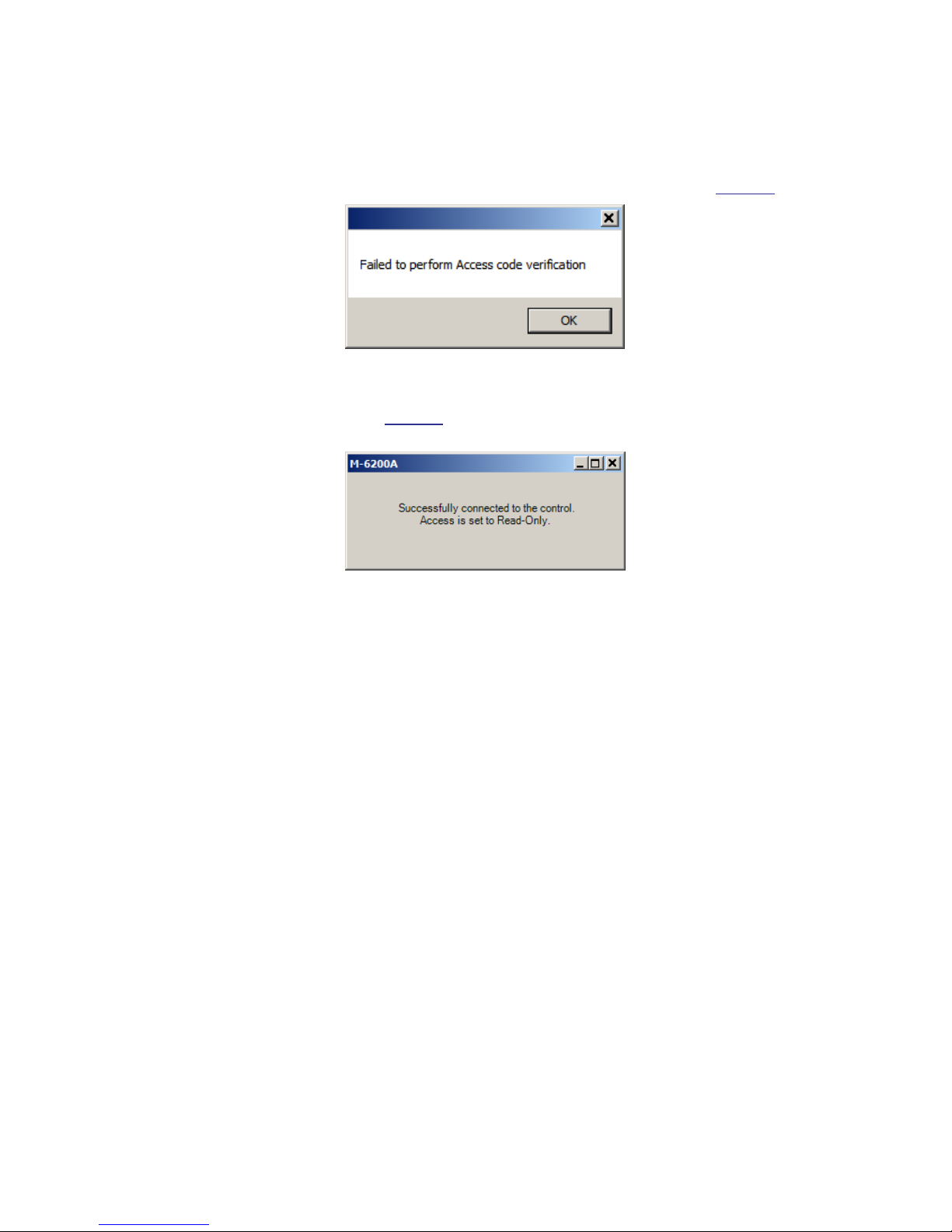
11. If Level 1 Access is active and an invalid access code was entered, then TapTalk will
display a "Failed to perform Access Code Verification" error message (Figure 13).
Figure 15 Failed to perform Access Code Verication Error Screen
12. Select OK. TapTalk will briefly display the "Successfully Connected Read-Only
Access" screen (Figure 14) and then display the connected version of the TapTalk
Main Screen with Read-Only permission.
Figure 16 Successfully Connected Read-Only Access Screen
–23–
Page 31

M-6200A Application Guide
This Page Left Intentionally Blank
–24–
Page 32

A HMI
A.1 HMI Menu Flow .............................................................. A–2
Figure A-1 Monitor Menu Flow .................................... A–2
Figure A-2 Setpoints Menu Flow ................................ A–3
Figure A-3 Configuration Menu Flow ........................... A–4
Figure A-4 Communication Menu Flow ........................ A–6
Figure A-5 Utilities Menu Flow ..................................... A–7
A.2 HMI Screen Review ....................................................... A–8
Monitor/Metering ............................................................ A–8
Monitor/Present Demand ............................................... A–9
Monitor/Demand History ................................................ A–9
Monitor/Energy Metering .............................................. A–10
Monitor/Status .............................................................. A–11
Monitor/Motor Current .................................................. A–14
Monitor/Harmonics ....................................................... A–14
Monitor/Tap Information ............................................... A–15
Setpoints/Profile Settings ............................................. A–17
Setpoints/Common Settings ......................................... A–17
Setpoints/Power Flow Forward ..................................... A–18
Setpoints/Power Flow Reverse ..................................... A–18
Setpoints/Voltage Reduction ........................................ A–19
Setpoints/Limits ............................................................ A–20
Setpoints/VAr Bias ....................................................... A–20
VAr Bias (Step) ............................................................ A–20
VAr Bias (Linear) .......................................................... A–21
Configuration/Tapchanger Type .................................... A–22
Configuration/Tap Settings ........................................... A–22
Configuration/Programmable Alarm ............................. A–24
Configuration/System Clock ......................................... A–24
Configuration/Mtr Current Profile .................................. A–24
Configuration/CBEMA Setup ........................................ A–25
Configuration/Harmonics Setup.................................... A–25
Configuration/Data Logging .......................................... A–26
Configuration/Run Through Neutral .............................. A–27
Configuration/Nameplate .............................................. A–27
Communication/Comm Settings ................................... A–30
Communication/Memory Card ...................................... A–31
Communication/Ethernet .............................................. A–32
Communication/HMI ..................................................... A–34
Communication/Bluetooth ............................................ A–34
Communication/RS232 ................................................. A–35
Utilities/Calibration-Test ................................................ A–36
Utilities/About ............................................................... A–38
Appendix – A
Q CYBER SECURITY NOTE:
When Cyber Security is enabled, access to any feature described in
this Chapter is subject to the Access Permissions Policy as designated
by the Security Policy Administrator.
A–1
Page 33
M-6200A Instruction Book
Status
ß à
Press ENT to view
Alarm Status
Press ENT to view
Input Status
Press ENT to view
Output Status
Press ENT to view
Regulator Status
Present Demand
ß à
Demand Interval
xx Min
Demand Load Voltage
xxx.x Volts
Demand Pri. Current
x.x Amps
Demand Pri. Watts
x.xx MW
Demand Pri. VArs
x.xx MVArs
Demand Pri. VA
x.xx MVA
MONITOR
ßUTIL SETPà
Energy Metering
ß à
Watt Hours Fwd E
x kWh
Lagging VAr Hours E
x kVArh
Watt Hours Rev E
x kWh
Leading VAr Hours E
x kVArh
Press ENT to reset
Energy Metering
Press ENT to perform
Master Reset
Demand History
ß à
Min Load Voltage E
xxx.x Volts
Max Load Voltage E
xxx.x Volts
Max Pri. Current E
x.x Amps
Max Primary Watts E
x.xx MW
Max Primary VArs E
x.xx MVAr
Max Primary VA E
x.xx MVA
PF @ Max VA
x.xxx PF
Press ENT to reset
Demand History
Press ENT to perform
Master Reset
Demand Interval
xx Min
Metering
ß à
Load Voltage
xxx.x Volts
Source Voltage
xxx.x V (Calculated)
Load Current
x.x mA Lag
Compensated Voltage
xxx.x Volts
Primary Voltage
x.xx kV
Primary Current
x.x Amps
Primary Watts
x.xx MW
Primary VArs
x.xx MVArs
Primary VA
x.xx MVA
Frequency
xx.x Hz
Power Factor
x.xxx Lead
Definite Timer
Raise= x Sec LO
Intertap Timer
xxx %
Tap Information
ß à
Tap Position/Cal
0
Operation Counter
0
Resettable Counter E
0
Drag Hands E
L= 0 N R= 0 N
Press ENT to view
specific Tap Stats
Press ENT to clear
Tap Statistics
Press ENT to view
Voltage Harmonics
Press ENT to view
Current Harmonic
Harmonics
ß à
Voltage % THD
x.x %
Profile Duration
xxxxx.x ms (xxxxx.x) T
Motor Current
ß à
Peak RMS Curr
x.x mA (x.x) T
Avg RMS Curr
x.x mA (x.x) T
Current % THD
x.x %
Neutral Sw Counter
x
Peak Motor Current E
x.x mA
Lower Counter
x
Raise Counter
xx
Primary Src Voltage
x.xx kV
Meter Out Voltage
xxx.x Volts
RTN Success Counter
xxxxx
Count to RTN Active
xxxxx
RTN Status
Disabled/Enabled/Counting
Battery Alarm Status
NOT ENABLED
A.1 HMI Menu Flow
A–2
Figure A-1 Monitor Menu Flow
At any menu screen:
Press EXIT to go to the Menu Header.
Press either to move sideways to the adjacent Menu
Header.
Page 34
LDC Selection*
RX
Timer Characteristic
DEFINITE
Timer Reset
INTEGRATING
Rev Power Operation
BLOCK
Power Direction Bias
NONE
Common Settings 1
ß à
Power Flow Fwd 1
ß
à
Bandcenter Fwd
xxx.x Volts
Bandwidth Fwd
x.x Volts
LDC R Fwd ßà
x Volts
LDC X Fwd
x Volts
Definite Delay Fwd
ßà
xx Sec
OR “Inverse
Delay Fwd”
OR “Inverse
Delay Rev”
Power Flow Rev 1
ß à
Bandcenter Rev
xxx.x Volts
Bandwidth Rev
x.x Volts
LDC R Rev ßà
x Volts
LDC X Rev
x Volts
Definite Delay Rev
ßà
xx Sec
SETPOINTS
ßMNTR CNFGà
Power Flow Reverse setting screens are only available when the
"Reverse Power Operation" selection under "Common Settings" is
selected to either REGULATE REVERSE, REG. R MEASURED SRC,
DISTRIBUTED GENERATION, AUTO DETERMINE or AUTO
DETERMINE MEASURED. If Distributed Generation is selected, then
only LDC values can be set.
Selecting BLOCK, IGNORE or RETURN TO NEUTRAL disables the
Power Flow Reverse setting screens.
VAr Bias Method
disable (Step, Linear)
Lead % Pickup
75
Lag % Pickup
75
VAr Bias Volt Step
1.0 Volts
Max VAR Bias Time
300 mins
VRed Turnoff Timer
0 Min
Smart VR
disable
Save VR at Power Off
DON"T SAVE
Standard VR
ENABLE
Voltage Reduction 1
ß à
VAr Bias 1
ß à
Limits 1
ß à
Block Raise Voltage
xxx.x Volts
Block Lower Voltage
xxx.x Volts
Dead Band
x.x Volts
Current Block Limit
xxx mA
VAr Bias Method
Step
Disable in Rev Pwr
disable
Fwd Max Cap Bnk Size
12000 KVAr
Rev Max Cap Bnk Size
12000 KVAr
*Selection is not
available when Linear
VAr Bias is enabled
Reduction Step 1 %
2.5
Reduction Step 2 %
5.0
Reduction Step 3 %
7.5
LDC Z Fwd ßà
x Volts
LDC Z Rev ßà
x Volts
Active Setpoint Profile or Setpoint
Profile Selected for Editing
Active Profile
Profile :1
Profile to Edit
Profile :1
Edit Profile 1 Name
xxxxx
Profile Settings
ß à
Repeats for
Profiles 2-4
VAr Bias Method
Linear
Disable in Rev Pwr
disable
Curr Mult Base Value
0
Linear V Bias -X
0 Volts
Linear V Bias -X Lmt
0.0 Volts
Normlzd Lin V Bias -X
x.x Volts
Linear V Bias +X Lmt
0.0 Volts
Linear V Bias +X
0 Volts
Normlzd Lin V Bias +X
x.x Volts
DG LDC R ßà
X Volts
DG LDC X
X Volts
AD Tap Limit Timer
60 Min
Appendix – A
At any menu screen:
Press EXIT to go to the Menu Header.
Press either to move sideways to the adjacent Menu Header.
Figure A-2 Setpoints Menu Flow
A–3
Page 35
M-6200A Instruction Book
Data Logging
ß à
Data Log Select
11111111111111
Data Log Interval
5 mins
Press ENT to clear
Data Log Records
Nameplate
ß à
CT Multiplier
6000 X
Load VT Multiplier
60.0 X
CT/Load VT Phasing
x Deg
Load VT Correction
x.x Volts
Regulator Type
TYPE A
Output Selection
CONTINUOUS
Output Pulse
X.X Sec
Tap Settings
ß à
Tap Information
INTERNAL KEEPTRACK
Tap Limits
disable
Op Counter Config
1 X
Tap Position/Cal
0
X Mode Delay
10 ms
Ntrl Counter Preset
XXXXXX
Prog Alarm Function
<0001100011100110
Pred. Maint. Alarm
0
System Clock
ß à
Set Date and Time
03/26/07 15:41:29
Daylight Savings
disable
CONFIGURATION
ßSETP COMMà
Source VT Multiplier
60.0 x
CT/Source VT Phasing
x Deg
Source VT Correction
x.x Volts
Input Selection 1
VOLTAGE RED 2
Motor Seal-In
disable
Harmonics Setup
ß à
V 17-31 Har. Alarm
000000001010101
V Alarm Threshold
x.x %
I
17-31 Har. Alarm
000000000010100
V 2-16 Har. Alarm
011111111111111
I
Alarm Threshold
x.x %
Harmonic Alarm Delay
x s
I
2-16 Har. Alarm
011111111111111
Op Counter Config
Count Window
Programmable Alarm
ß à
Counter Time Window
0.5 Sec
Op Counter Preset
XXXXXX
Raise Counter Preset
XXXXXX
Min
I
Thresh. ENABLE
ENABLE
Norm. VT. Multiplier
1.00 x
Min Fund I Threshold
xx mA
When Min I Threshold
is Enabled
Motor Seal-In Delay
10 ms
Clear Sealin Alarm
Ready Press Enter
Low Current Block
disable
Clr Low Current Blk
Ready Press Enter
Seal-In Fail Block
disable
When Motor Seal-in
is ENABLED
When Count Window
is Enabled
Max Allowed Taps
x
Taps Between Runs
xxxxx
Enable/Disable
disable
Max Load Current
xx mA
Max RTN Standby Ops
xxxxx
Run Through Neutral
ß à
Tapchanger Type
ß à
Tapchanger Type
REGULATOR TYPE A
Regulator Vendor
Default
Maximum Tap Wear
Clr Run T. Neu Alarm
Ready Press ENTER
Reset Success Cntr
Ready Press ENTER
MS Current Pickup
250 mA
MS Current Dropout
240 mA
MS Current Duration
35 ms
VAr/PF Alrm Time Dly
x Sec
Lagging PF Alarm
xxx PF
Min I for PF Alarms
xx mA
Leading VAr Alarm
xxxx kVAr
Lagging VAr Alarm
xxxx kVAr
Leading PF Alarm
xxx PF
Comm Block Auto
DON"T SAVE
Scamp Init Pwrup
AUTO
When SCAMP
Option purchased
Intertap Delay
x Sec
Input Selection 2
VOLTAGE RED 1
Input Selection 3
NON SEQUENTIAL
Clr Abnrml Tap Alarm
Ready Press ENTER
Tap Block Raise
xx
Tap Block Lower
xx
When Enabled
At any menu screen:
Press EXIT to go to the Menu Header.
Press either to move sideways to the adjacent Menu Header.
Figure A-3 Conguration Menu Flow (1 of 2)
A–4
Page 36
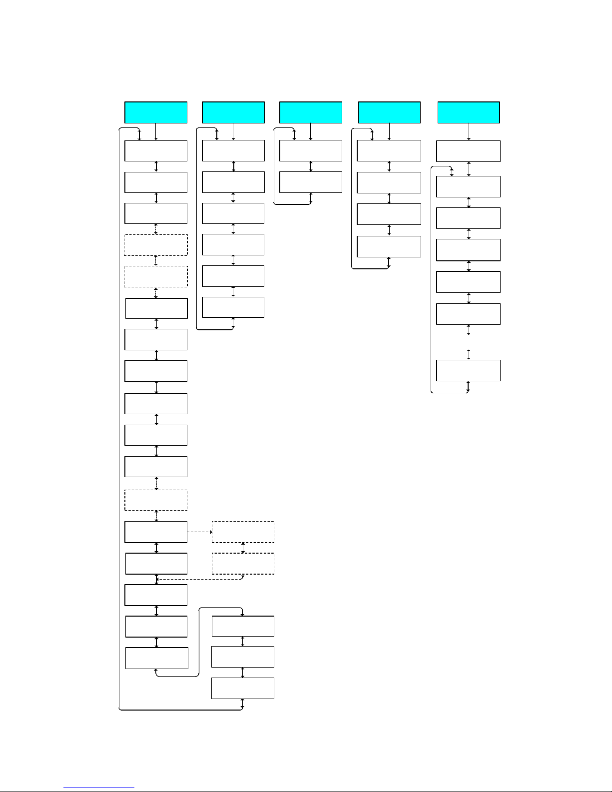
Appendix – A
Tap Settings
ß à
Tap Information
INTERNAL KEEPTRACK
Tap Limits
disable
Op Counter Config
1 X
Tap Position/Cal
0
X Mode Delay
10 ms
Ntrl Counter Preset
XXXXXX
Prog Alarm Function
<0001100011100110
Pred. Maint. Alarm
0
System Clock
ß à
Set Date and Time
03/26/07 15:41:29
Daylight Savings
disable
Peak RMS % Change
xxx
Average RMS % Change
xxx
Duration % Change
xxx
Init. Motor Current
Press ENT to reset.
Motor Seal-In
disable
Mtr Current Profile
ß à
Op Counter Config
Count Window
Programmable Alarm
ß à
Counter Time Window
0.5 Sec
Op Counter Preset
XXXXXX
Normal Voltage
xxx.x Volts
Event 1
ENABLE
Event1 Sag Pickup
xx %
Event1 Sag Dropout
xx %
CBEMA Setup
ß à
Event1 Sag Min Dur
x Cycles (xx ms)
Repeats for
Events 2 thru 4
Clear All Counters
Ready Press ENTER
Lower Counter Preset
XXXXXX
Raise Counter Preset
XXXXXX
Motor Seal-In Delay
10 ms
Clear Sealin Alarm
Ready Press Enter
Clr Low Current Blk
Ready Press Enter
Seal-In Fail Block
disable
When Motor Seal-in
is ENABLED
When Count Window
is Enabled
Maximum Tap Wear
065534
Indvdl Tap Wear Alrm
100%
Clr Run T. Neu Alarm
Ready Press ENTER
MS Current Pickup
250 mA
MS Current Dropout
240 mA
MS Current Duration
35 ms
Use Taptalk for
CBEMA in SOE or OSC
Intertap Delay
x Sec
Clr Abnrml Tap Alarm
Ready Press ENTER
Tap Block Raise
xx
Tap Block Lower
xx
When Enabled
At any menu screen:
Press EXIT to go to the Menu Header.
Press either to move sideways
to the adjacent Menu Header.
Figure A-3 Conguration Menu Flow (2 of 2)
A–5
Page 37
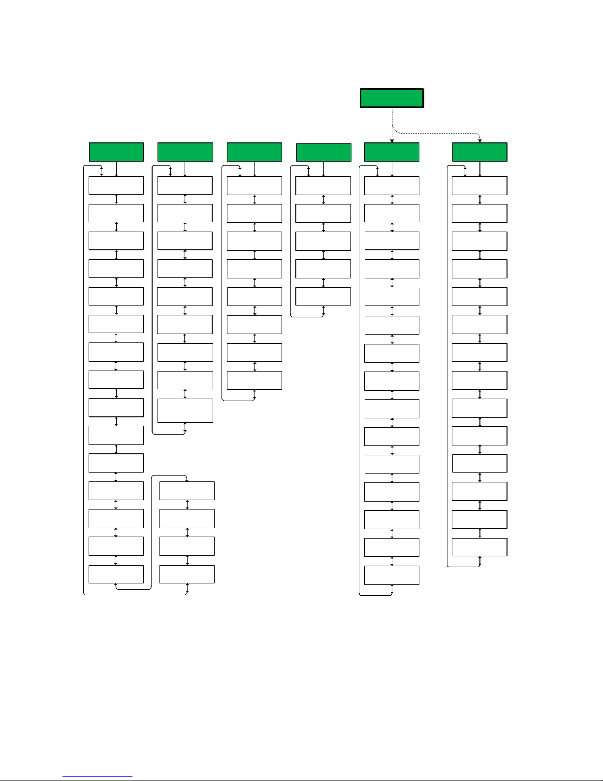
M-6200A Instruction Book
HMI
ß à
Set LCD Contrast: E
Level 1 Access Code
Press ENT to change
Oscillograph Message
ENABLE
User Line 1 E
Beckwith Electric
User Line 2 E
M-6200A
Enter DNP Port
20000
Ethernet
ß à
DHCP Enable
ENABLE
IP Address
0.0.0.0
Net Mask
0.0.0.0
Gateway
0.0.0.0
Enter Modbus Port
502
RS232
ß à
Protocol
MODBUS
Stop Bits
ONE STOPBIT
Sync Time
50 ms
Baud Rate
115200
Parity
NONE
Comm Settings
ß à
Comm Port Type
RS485
Comm Protocol
DNP3.0
Comm Address
DNP 1 Mdbus 1
Baud Rate
9600
Parity
NONE
Stop Bits
ONE STOPBIT
Sync Time
2 ms
DNP Configuration
M-6200A DNP DEFAULT
Bluetooth
ß à
Bluetooth Enable
ENABLE
Bluetooth Reset
Ready Press ENTER
Bluetooth Protocol
MODBUS
Authentication
disable
Bluetooth Pass Reset
Ready Press ENTER
Keepalive Time
120 sec
Auto Negotiation
ENABLE
Level 2 Access Code
Press ENT to change
Clear Osc Records
Ready Press ENTER
Friendly Name
M6200A
Src Addr Validation
disable
Substation Address
DNP 0 Mdbus 0
Feeder Address
DNP 0 Mdbus 0
If Memory Card is present, then the first menu
to be displayed under Communication is the
Memory Card menu, otherwise the Memory
Card menu is not displayed.
COMMUNICATION
ßCNFG UTILà
Firmware Update
Press ENT to begin
Memory Card
ß à
Load Setpoints
Press ENT to begin
Save Setpoints
Press ENT to begin
Save Datalog
Press ENT to begin
Load DNP Config
Press ENT to begin
Save DNP Config
Press ENT to begin
Save seq. of events
Press ENT to begin
Save oscillograph
Press ENT to begin
Clone save
Press ENT to begin
Clone load
Press ENT to begin
Comm Access Security
disable
Comm Access Timeout
60 sec
Output Pulse
1.5 Sec
Save Metering Data
Press ENT to begin
TX Delay
10 ms
SD Quick Capture
Press ENT to begin
Bluetooth Mode
MODE0
Control BT Device
xx:xx:xx:xx:xx:xx
Load User config
Press ENT to begin
Load IPsec config
Press ENT to begin
Radius Secret Code
Press ENT to change
IEEE 1686 Standard
not used/
Authen with Encryp*
*NOTE: Once IEEE 1686 Standard cyber security
is enabled, the user must enter a valid User Name
and Password to access any menus other than the
"Utilities/About" menu. This selection cannot be
changed to "not used" without entering a valid User
Name and Password.
Radius Server 1 IP
xx.xx.xx.xxx
Radius Server 2 IP
xx.xx.xx.xxx
Radius 1 Auth. Port
1812
Radius 1 Acc. Port
1813
Radius 2 Acc. Port
1815
Radius 2 Auth. Port
1814
Radius En./Dis.
disable
SNTP IP Address
xx.xx.xxx.xx
SNTP En./Dis.
disable
IPSEC En./Dis.
disable
Time Zone GMT
–5 Hr
At any menu screen:
Press EXIT to go to the Menu Header.
Press either to move sideways to the adjacent Menu Header.
A–6
Figure A-4 Communication Menu Flow
Page 38
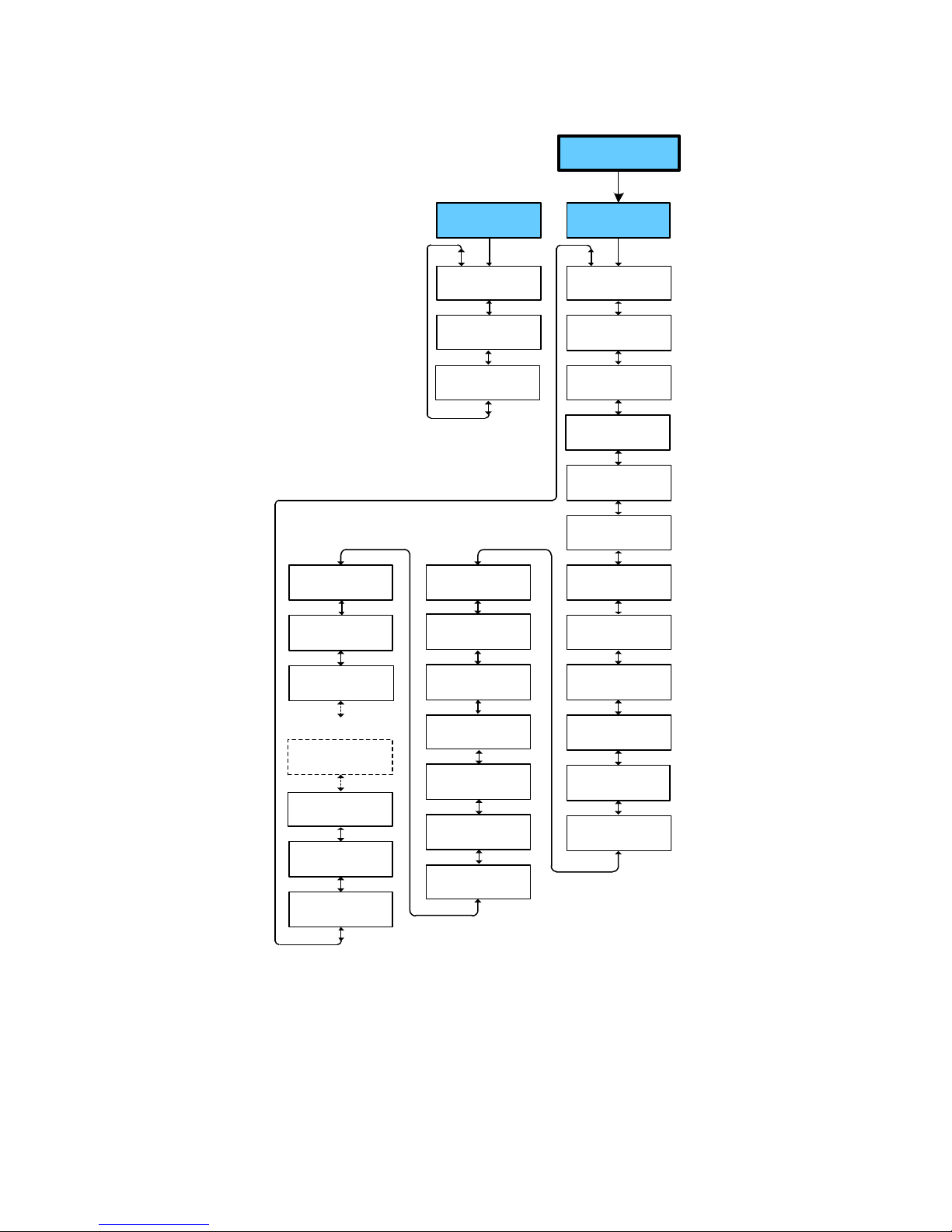
UTILITIES
ßCOMM MNTRà
About
ß à
Serial Number
xxxxx
Firmware Version
D-0228Vxx.xx.xx
Calibration/Test
ß à
Volt Cal Coefficient
32767 X
Load Voltage
XXX.X Volts
Bias Voltage
Status/Test Mode
Control Load I
x.x mA Lead
Curr Cal Coefficient
32767 X
Power Factor
x.xxx Lead
I
Sin Coefficient
0 X
Motor Current
xx.x mA
I
Cos Coefficient
8192 X
Mtr Cal. Coefficient
8192 X
Mtr Sin Coefficient
0 X
Volt Rms Coefficient
32767 X
EE Checksum
XXXXXX
LED Scroll Test
Press ENT to begin
Input Test
Press ENT to Begin
Output Test
Press ENT to test
Button Input Test
Press ENT to Begin
Change Src Input
press ENTER.
Mtr Cos Coefficient
8192 X
Mtr RMS Coefficient
8192 X
Watchdog resets: 0
Total resets: XX
Clear reset counters
Press ENT to begin
X1 Duration
x ms, Avg: x ms
Motor Sealin Pulse
x ms, Avg: x ms
When Motor Seal-in
ENABLED
Comm Options En/Dis
01111111111111
Init Setpoints
Press ENT to begin
Erase Flash Files
Press ENT to begin
Appendix – A
At any menu screen:
Press EXIT to go to the Menu Header.
Press either to move sideways to the adjacent Menu Header.
Figure A-5 Utilities Menu Flow
A–7
Page 39
M-6200A Instruction Book
A.2 HMI Screen Review
Monitor/ Metering
Load Voltage
xxx.x Volts
Meter Out Voltage
xxx.x Volts
Source Voltage
XXX.X V (Calculated)
Load Current
x.x mA Lag
Compensated Voltage
xxx.x Volts
Primary Voltage
x.xx kV
Displays the real-time measured value of voltage at the
regulator or the transformer, including the voltage reduction if
applicable and any corrections made using the user-selected
VT correction voltage.
Displays the measured voltage at the terminals of the M-6200A
without any software modifications. Used as the base for
normalizing voltage.
Displays the real-time calculated source voltage-only applicable
in regulator control applications and includes any corrections
made using the user-selected VT correction voltage.
Displays the real-time measured value of load current related to
the scaling factor Current Transformer of 200 mA.
Displays the calculated voltage at the "load center," based on
load current and the LDC settings.
Displays the calculated primary voltage based on the user-
selected voltage multiplier and measured secondary voltage.
Primary Src Voltage
x.xx kV
Primary Current
x.x Amps
Primary Watts
x.xx MW
Primary VArs
x.xx MVArs
Primary VA
x.xx MVA
Displays Primary Source Voltage based on the user-selected
Source VT Correction.
Displays the calculated primary current based on the user-
selected current multiplier and measured secondary current.
Displays the calculated primary quantity based on the user-
selected multipliers and measured secondary voltage and
current.
Displays the calculated primary quantity based on the user-
selected multipliers and measured secondary voltage and
current.
Displays the calculated primary quantity based on the user-
selected multipliers and measured secondary voltage and
current.
A–8
Figure A-6 Monitor Screens (page 1 of 9)
Page 40
Monitor/Metering (Cont'd)
Appendix – A
Power Factor
X.XXX Lead
Frequency
xx.x Hz
Monitor/Present Demand
Demand Interval
xx Min
Demand Load Voltage
xxx.x Volts
Demand Pri. Current
x.x Amps
Displays the real-time calculated value of power factor.
Displays the line frequency.
Toggles between 5, 10, 15, 30 and 60 minute interval with a
factory setting of 15 minutes. The time interval is the amount of
time it takes for a thermal meter to indicate 90% of a change of
load.
Displays the real-time measured value of voltage at the
regulator or transformer. This value continuously averaged over
consecutive 32-second intervals.
Displays the calculated primary demand current based on
the user-selected current multiplier and measured secondary
current.
Demand Pri. Watts
x.xx MW
Demand Pri. VArs
X.XX MVArs
Demand Pri. VA
x.xx Mva
Monitor/Demand History
Demand Interval
xx Min
Min Load Voltage E
xxx.x Volts
Max Load Voltage E
xxx.x Volts
Displays the demand value base on the user-selected voltage
and current multipliers or secondary voltage and current.
Displays the demand value based on the user-selected voltage
and current multipliers and measured secondary voltage and
current.
Displays the demand value based on the user-selected voltage
and current multipliers and measured secondary voltage and
current.
Toggles between 5, 10, 15, 30 and 60 minute interval with a
factory setting of 15 minutes. The time interval is the amount of
time it takes for a thermal meter to indicate 90% of a change of
load.
Displays minimum local voltage at the regulator or transformer.
Bottom line toggles between date/time/Volts.
Displays maximum local voltage at the regulator or transformer.
Bottom line toggles between date/time/Volts.
Figure A-6 Monitor Screens (page 2 of 9)
A–9
Page 41
M-6200A Instruction Book
Monitor/Demand History (Cont'd)
Max Pri. Current E
X.X Amps
Max Primary Watts E
x.xx MW
Max Primary VArs E
X.XX MVAr
Max Primary VA E
X.XX MVA
PF @ Max VA
x.xXX PF
Press ENT to reset
Demand History
Displays maximum primary current. Bottom line toggles
between date/time/Amps.
Displays maximum Watts. Bottom line toggles between date/
time/W.
Displays maximum VAr. Bottom line toggles between date/time/
VAr.
Displays maximum VA. Bottom line toggles between date/time/
VA.
Displays power factor at time of maximum VA. Resets
automatically when MAX VA screen, below, is reset.
Press ENT to perform
Master Reset
Monitor/Energy Metering
Watt Hours Fwd E
x kWh
Lagging VAr Hours E
x kVArh
Watt Hours Rev E
x kWh
Leading VAr Hours E
x kVArh
Press ENT to reset
Energy Metering
Displays total forward WHr. Bottom line toggles between date/
time/WHr.
Displays total forward VArHr. Bottom line toggles between date/
time/VArHr.
Displays total reverse WHr. Bottom line toggles between date/
time/WHr.
Displays total reverse VArHr. Bottom line toggles between date/
time/VArHr.
Press ENT to perform
Master Reset
A–10
Figure A-6 Monitor Screens (page 3 of 9)
Page 42
Monitor/Status
Press ENT to view
Regulator Status
Appendix – A
TAP BDS PWR BLK VRD
1 OK fwd blk Off
The following screens can be viewed for additional information by depressing the Down Arrow pushbutton,
TAP Tap Position*
BDS Band Status (Lo, Hi, In Band)
PWR Power Direction (Fwd, Rev, Auto Determination)
BLK Blocks in Effect
VRD Voltage Reduction (Off, 1, 2, 3)
*In order to verify Neutral Tap Position, when the tap
position is "0", but no neutral input is detected, the Tap
Position screen will display "- - -" instead of "0".
Tap Position
0
Band Status
In Band, High, Low
Power Direction
Forward, Reverse
Auto Determination
Forward
When Reverse Power mode is set to Auto Determination or
Auto Determination Measured, the displayed value is one of the
following:
• Dist Gen
• RegRev – Regulate in Reverse
• Forward – Forward Power mode
• Dist G en - Eval – DG Test mode
• RegRev - Eval – Regulate in Reverse Test Mode
• Forward - Eval – Forward Test Mode
– DG mode
Figure A-6 Monitor Screens (page 4 of 9)
A–11
Page 43
M-6200A Instruction Book
Monitor/Status (Cont'd)
Blocks in Effect
-- -- -- -- -- -- --
Blocks in Effect are indicated from left to right (Position 1 to
7). Multiple blocks may be in effect and therefore the display is
prioritized as follows:
NOTE:Q Blocks are listed in order of display priority from top
to bottom.
Position Block Display
1 Line Limit LL
2 Force Lower FL
2 Voltage Limit Block Lower BL
2 Voltage Limit Block Raise BR
3 Tap Limit Block Lower TL
3 Tap Limit Block Raise TR
4 Non-Sequential Block NS
4 Seal-in Failure Block Raise and Lower SB
4 Seal-in Failure Block Raise SR
4 Seal-in Failure Block Lower SL
4 Low Current Block IB
5 Comm Block CB
6 Reverse Power Block RP
7 SCADA Cutout Local SC
Voltage Reduction
Off, 1, 2, 3
Press ENT to view
Alarm Status
i
ABCDEFGHIJKLMNOP– >
0000––0––––00X––
< – Q R S T U V W
– – – – – – –
A = Block Raise Tap
B = Block Lower Tap
C = Block Raise Voltage
D = Block Lower Voltage
E = Voltage Reduction
F = Power Direction
G = Current Limit
H = Comm Block
I = LDC/LDZ
J = Selftest
K = Seal-in Failure
L = VAr Bias Lag
Alarm Status Key
1 Alarm Enabled/Condition Met
0 Alarm Enabled/Condition Not Met
X Alarm Disabled/Condition Met
– Alarm Disabled/Condition Not Met
M = VAr Bias Lead
N = Backup Fail
O = Abnormal Tap Position
P = Low Current Blk
Q = RTN Fail
R = Op Count Signal
S = Individual Tap Wear
T = Leading VAr
U = Lagging VAr
V = Leading PF
W = Lagging PF
A–12
Figure A-6 Monitor Screens (page 5 of 9)
Page 44
Monitor/Status (Cont'd)
Press ENT to view
Input Status
i
C NS V d KT N MS
0 0 -- 0 RL 0 0
Appendix – A
C = Counter Contact
NS = Non-Sequential Input
VR = Voltage Reduction Inputs 1 and 2
DH = Drag Hands Reset Input
KT = KeepTrack Lower and Raise Input
N = Neutral Input
MS = Motor Seal-In Input
Key
1 = True (on)
0 = False (off)
For VR
- - = No Voltage Reduction Steps in effect
1 - = Voltage Reduction Step 1 in effect
- 2 = Voltage ReductionStep 2 in effect
1 2 = Voltage Reduction Step 3 in effect
For KT
- - = No Raise or Lower inputs active
R - = Raise Input detected
- L = Lower Input detected
RL = Motor power is not connected or circuit failure.
Press ENT to view
Output Status
i
raise lower alarm
LOWER Lower Output Contact
1 0 0
ALARM Alarm Output Contact
Battery Alarm Status
NOT ENABLED
Figure A-6 Monitor Screens (page 6 of 9)
RAISE Raise Output Contact
Key
1 = True (on)
0 = False (off)
When the optional Battery Pack sense line is connected to
TB1-1 and Input Selection 3 (Non-Sequential) is configured as
"Aux 2", this screen will display the Battery Alarm Status as
"BATTERY OK!" or "BATTERY LOW!".
A–13
Page 45
M-6200A Instruction Book
Monitor/Motor Current
Peak RMS Curr
X.X mA (X.X) T
Avg RMS Curr
X.X mA (X.X) T
Profile Duration
XXXXX.X ms (XXXXX.X) T
Peak Motor Current E
X.X mA
Monitor/Harmonics
Voltage % THD
X.X %
Displays the Peak RMS Current of the last operation (profile).
Also displays the average Peak RMS Current from the Training
Mode ( ). If a "T" is present, the Training Mode is active.
Displays the Average RMS Current of the last operation (profile).
Also displays the average of the Average RMS Current from
the Training Mode ( ). If a "T" is present, the Training Mode is
active.
Displays the Profile Duration of the last operation (profile). Also
displays the average of the Profile Duration from the Training
Mode ( ). If a "T" is present, the Training Mode is active.
Displays the Peak Motor Current recorded. This parameter is
the highest Peak Motor Current recorded by the control. This
parameter is independent of the Peak RMS Current in the
Motor Current Profile.
Displays the percent of Voltage THD.
Current % THD
X.X %
Press ENT to view
Voltage Harmonics
Press ENT to view
Current Harmonic
Displays the percent of Current THD.
Allows the user to view individual Voltage Harmonic Values
(2-31).
Allows the user to view individual Current Harmonic Values
(2-31).
A–14
Figure A-6 Monitor Screens (page 7 of 9)
Page 46
Monitor/Tap Information
Appendix – A
Tap Position/Cal
0
Drag Hands E
L= 0 N R= 0 N
Definite Timer
Raise= X Sec LO
Intertap Timer
xxx %
Operation Counter
0
Displays the tap position of the tapchanger. Recognizes
tapchanges commanded via manual, automatic or external
(SCADA) means, if tap position is not disabled. The tap position
can be calibrated by selecting ENT, then setting the tap position
using the / pushbuttons and selecting ENT to confirm the
new tap position.
NOTE:Q In order to verify Neutral Tap Position, when the tap
position is "0", but no neutral input is detected, the
Tap Position screen will display "- - -" instead of "0".
Displays minimum and maximum values of tap position since
reset. (Section 2.2)
Displays the status of the raise and lower timers; inverse or
linear.
Displays the status of the intertap timer.
Records the total number of raise and lower operations. The
operation counter will advance by one or two counts, as set by
user, for each open-close-open contact operation. This counter
is not resettable, but can be preset to any value between 0 and
999,999.
Resettable Counter E
0
Neutral Sw Counter
x
Lower Counter
x
Raise Counter
xx
Records the total number of raise and lower operations as does
the total operations counter, discussed above. This counter is
reset by pressing ENT at this screen. This counter can be used
to monitor the number of tapchanges since the last time it was
checked.
The Neutral Switch Counter is updated each time the neutral
input is detected. Neutral Switch Counter can also preset to
any value. The Neutral Switch Counter is a software counter
that is stored in non-volatile memory and has a maximum value
of 999,999.
Records the number of Lower operations, can be Preset/Reset
in Configuration/Tap Settings.
Records the number of Raise operations, can be Preset/Reset
in Configuration/Tap Settings.
Figure A-6 Monitor Screens (page 8 of 9)
A–15
Page 47
M-6200A Instruction Book
Monitor/Tap Information (Cont'd)
Press ENT to view
specific Tap Stats
i
Tap Tap Number
TAP Number = The number of tapchanges and the Accumulated
X X X.X A
Press ENT to clear
TAP = Tap Position
Primary Current at this position.
Press ENT to confirm clearing tap statistics.
Tap Statistics
RTN Success Counter
xxxxx
RTN Status
Disabled/Enabled/Counting
Count To RTN Active
xxxxx
The RTN Success counter increments after each successful
operation of the Run Through Neutral feature.
Displays the status of the Run Through Neutral Feature.
Displays the number of counter operations since the operations
between runs setting was set, or since the feature was enabled.
The counter will reset to zero if the feature is enabled and
successfully runs through neutral.
A–16
Figure A-6 Monitor Screens (page 9 of 9)
Page 48
Setpoints/Profile Settings
Appendix – A
Active Profile
Profile: 1
Profile to Edit
Profile: 1
Edit Profile 1 Name
"Empty"
Setpoints/Common Settings
LDC Selection
RX
Timer Characteristic
DEFINITE
Provides the means to select the Active Profile (1, 2, 3 or 4).
Selects the Setpoint Profile to be edited (1, 2, 3 or 4).
Allows the user to assign a profile (1, 2, 3 or 4) name up to
20 standard alphanumeric characters. Alpha characters may be
either upper or lower case.
Allows the user to select between Line Drop Compensation
Resistance/Reactance or Z.
Allows setting control timer for Definite or Inverse time. There
are four setpoints associated with this selection: Time Delay
F/R, and Inverse Time F/R.
Timer Reset
INTEGRATING
Rev Power Operation
BLOCK
Power Direction Bias
NONE
Toggles between integrating timer and instantaneous reset
(INST_RESET) timer upon voltage return to in-band condition.
Toggles between eight modes of operation:
• BLOCK – to inhibit automatic tapchange operation
(Factory Setting)
• REGULATE REVERSE/REG. R MEASURED SRC – to
detect a reverse power condition and regulate according
to reverse power settings
• RETURN TO NEUTRAL – to drive the tap position to
Neutral
• IGNORE – to continue unit action as though Forward
Power Flow continued to exist
• DG Mode (Distributed Generation) – when distribution
systems have the possibility of power reversal to control
voltage
• AUTO DETERMINE/AUTO DETERMINE M – to allow
the control to intelligently choose which reverse power
mode applies at the time reverse power is sensed, either
Distributed Generation mode or Regulate In Reverse/
Regulate in Reverse Measured
Allows one of three methods to be used for the control to switch
between forward/reverse power operation. The three settings
are None, Forward Bias, and Reverse Bias.
Figure A-7 Setpoints Screens (page 1 of 5)
A–17
Page 49
M-6200A Instruction Book
Setpoints/Power Flow Forward
Bandcenter Fwd
xxx.x Volts
Bandwidth Fwd
x.x Volts
LDC R Fwd
x Volts
LDC X Fwd
x Volts
LDC-Z Fwd
x Volts
Definite Delay Fwd
xx Sec
Inverse Delay Fwd
xx Sec
Forward power bandcenter is adjustable from 100.0 V to 135.0
V in 0.1 V increments with a factory setting of 120.0 V.
Forward power bandwidth is adjustable from 1.0 V to 10.0 V in
0.1 V increments with a factory setting of 2.0 V.
Forward power Line Drop Compensation resistance is
adjustable from -72 V to +72 V in 1 V increments with a factory
setting of 0 V.
Forward power Line Drop Compensation reactance is adjustable
from -72 V to +72 V in 1 V increments with a factory setting of
0 V.
When Line Drop Compensation is set to Z, adjustable from 0 to
72 volts in 1 volt increments.
Forward power time delay for a tapchange is adjustable from
1 sec. to 360 sec. in 1 second increments with a factory setting
of 30 sec.
Forward power inverse delay for a tapchange is adjustable from
1 sec. to 360 sec. in 1 second increments with a factory setting
of 30 sec.
Setpoints/Power Flow Reverse
Bandcenter Rev
XXX.X Volts
Bandwidth Rev
X.X Volts
LDC R Rev
X Volts
LDC X Rev
X Volts
LDC-Z Rev
X Volts
Definite Delay Rev
xx Sec
Reverse power bandcenter is adjustable from 100.0 V to 135.0
V in 0.1 V increments with a factory setting of 120.0 V.
Reverse power bandwidth is adjustable from 1.0 V to 10.0 V in
0.1 V increments with a factory setting of 2.0 V.
Distributed Generation Line Drop Compensation resistance is
adjustable from -72 V to +72 V in 1 V increments with a factory
setting of 0 V.
Distributed Generation Line Drop Compensation reactance is
adjustable from -72 V to +72 V in 1 V increments with a factory
setting of 0 V.
When Line Drop Compensation is set to Z, the Distributed
Generation LDC is adjustable from 0 to 72 volts in 1 V
increments.
Reverse power time delay for a tapchange is adjustable from 1
sec. to 360 sec. in 1 second increments with a factory setting of
30 sec.
A–18
Figure A-7 Setpoints Screens (page 2 of 5)
Page 50
Setpoints/Power Flow Reverse (Cont'd)
Appendix – A
Inverse Delay Rev
xx Sec
DG LCR R
X Volts
DG LCR X
X Volts
DG LCR Z Rev
X Volts
AD Tap Limits Timer
XX Min
Setpoints/Voltage Reduction
Standard VR
ENABLE
Reverse power inverse delay for a tapchange is adjustable from
1 sec. to 360 sec. in 1 second increments with a factory setting
of 30 sec.
Distributed Generation Line Drop Compensation resistance is
adjustable from -72 V to +72 V in 1 V increments with a factory
setting of 0 V.
Distributed Generation Line Drop Compensation reactance is
adjustable from -72 V to +72 V in 1 V increments with a factory
setting of 0 V.
When Line Drop Compensation is set to Z, the Distributed
Generation LDC is adjustable from 0 to 72 volts in 1 V
increments.
The Auto Determination Tap Limits Timer setting is adjustable
from 1 min. to 1440 min. in 1 minute increments with a factory
setting of 60 min.
Allows the user to enable or disable the Standard Voltage
Reduction feature.
VRed Turnoff Timer
0 min
Smart VR
disable
Save VR at Power Off
DON'T SAVE
Reduction Step 1 %
2.5
Reduction Step 2 %
5.0
Reduction Step 3 %
7.5
The Voltage Reduction feature can be turned off after a time
period of 1 to 999 minutes. A setting of zero disables the Voltage
Reduction Turnoff Timer.
Allows the user to Enable or Disable Smart Voltage Reduction
on the Control. Smart Voltage Reduction, when enabled, lowers
voltage to between the Bandcenter setting and the lower
band edge instead of stopping at the upper band edge. It also
disablesVAr Bias if it is in effect.
Allows any Voltage Reduction command communicated to the
control to be saved or not saved at power down.
Voltage reduction can be achieved by contact or communication
methods. First of three independent steps of voltage reduction
adjustable from 0% to 10% in 0.1% increments of the bandcenter
setpoint. Factory setting is 2.5% .
Voltage reduction can be achieved by contact or communication
methods. Second voltage reduction step. Factory setting is 5.0%.
Voltage reduction can be achieved by contact or communication
methods. Third voltage reduction step. Factory setting is 7.5%.
Figure A-7 Setpoints Screens (page 3 of 5)
A–19
Page 51
M-6200A Instruction Book
Setpoints /Limits
Block Raise Voltage
xxx.x Volts
Block Lower Voltage
xxx.x Volts
Dead Band
x.x Volts
Current Block Limit
xxx mA
Overvoltage limit is adjustable form 95.0 V to 135.0 V in 0.1 V
increments with a factory setting of 128.0 V. The Block Raise
setpoint should always be set above the Block Lower setpoint
and above the upper band limit (the bandcenter plus one-half
of the bandwidth) for the control to operate. All automatic Raise/
Lower tap operations are blocked, when input voltage is less
than 85.0 Vdc.
Undervoltage limit is adjustable from 95.0 V to 135.0 V in 0.1 V
increments with a factory setting of 114.0 V. The Block Lower
setpoint should always be set below the Block Raise setpoint
and below the lower band limit (the bandcenter minus one-half
of the bandwidth) for the control to operate. All automatic Raise/
Lower tap operations are blocked, when input voltage is less
than 85.0 Vdc.
Dead band is adjustable from 1.0 V to 4.0 V in 0.1 V increments
with a factory setting of 2.0 V.
Current Block Limit is adjustable from 50 mA to 640 mA in 1 mA
increments with a factory setting of 400 mA with hysteresis of 5
mA. If the value of the current exceeds the Current Block Limit
setpoint, the unit will not permit automatic control.
Setpoints/VAr Bias
VAr Bias Method
disable
VAr Bias (Step)
Disable in Rev Pwr
disable
Fwd Max Cap Bank Size
12000 KVAr
Rev Max Cap Bank Size
12000 KVAr
Lead % Pickup
75
Lag % Pickup
75
Enables either "Step" or "Linear" VAr Bias method or disables
the VAr Bias feature.
Allows Step VAr Bias to be disabled in the reverse power mode.
When Step VAr Bias is enabled provides the user with the ability
to set the largest capacitor bank size in the forward mode from
4 to 12,000 KVAr.
When Step VAr Bias is enabled provides the user with the ability
to set the largest capacitor bank size in the reverse mode from
4 to 12,000 KVAr.
Defines a Lower negative VAr limit in percentage of the Max
Cap Bank size below which the control will increase the upper
band edge by the amount defined by VAr Bias Voltage Step.
Defines an Upper positive VAr limit in percentage of the Max
Cap Bank size above which the control will decrease the lower
band edge by the amount defined by VAr Bias Voltage Step.
A–20
Figure A-7 Setpoints Screens (page 4 of 5)
Page 52
VAr Bias (Step) (Cont'd)
Appendix – A
VAr Bias Volt Step
1.0 Volts
Max VAR Bias Time
300 mins
VAr Bias (Linear)
Disable in Rev Pwr
disable
Curr Mult Base Value
0
Linear V Bias -X
0 Volts
Normlzd Lin V Bias -X
x.x Volts
Amount by which the control will increase or decrease the
Upper or Lower band edges when there is a VAr Bias out of
band situation.
Maximum allowable time in minutes the control will bias the
voltage edge.
Allows Linear VAr Bias to be disabled in the reverse power
mode.
Allows the Current Multiplier Base Value to be set between 0
and 32600.
The "No Voltage Reduction" Linear Voltage Bias (-X) setting
defines the amount of voltage bias to be applied to the
Bandcenter when at 1 PU reactive current loading. Adjustable
from -72 to 0 Volts at 200mA Reactive Load.
The Normalized Linear VAr Bias -X Volts display allows the user
to observe the Normalized Linear VAr Bias -X setting as a result
of the Normalizing value entered in Configuration.
Linear V Bias -X Lmt
0.0 Volts
Linear V Bias +X
0 Volts
Normlzd Lin V Bias +X
x.x Volts
Linear V Bias +X Lmt
0.0 Volts
The "No Voltage Reduction" Linear Voltage Bias (-X) Limit, limits
the total voltage bias that can affect the control Bandcenter.
Adjustable from -5.0 to 0.0.
The "During Voltage Reduction" Linear Voltage Bias (+X)
setting defines the amount of voltage bias to be applied to the
Bandcenter when at 1 PU reactive current loading. Adjustable
from 0 to 72 Volts at 200mA Reactive Load.
The Normalized Linear VAr Bias +X Volts display allows the
user to observe the Normalized Linear VAr Bias +X setting as a
result of the Normalizing value entered in Configuration.
The "During Voltage Reduction" Linear Voltage Bias (+X)
Limit, limits the total voltage bias that can affect the control
Bandcenter. Adjustable from 0.0 to 5.0 Volts.
Figure A-7 Setpoints Screens (page 5 of 5)
A–21
Page 53
M-6200A Instruction Book
Configuration/ Tapchanger Type
Tapchanger Type
REGULATOR TYPE A
Regulator Vendor
Default
Configuration/ Tap Settings
Tap Position/Cal
0
Tap Information
INTERNAL KEEPTRACK
Tap Limits
disable
Tap Block Raise
xx
Displays the vendor specific regulator configuration selected in
TapTalk. See Section 4.4, TapChanger Type Selections.
Allows input of known tap position to calibrate the unit tap
position. This function is disabled when Tap Information is
disabled.
NOTE:Q In order to verify Neutral Tap Position, when the tap
position is "0", but no neutral input is detected, the
Tap Position screen will display "- - -" instead of "0".
Toggles between Motor Direct Drive KeepTrack and disable.
Allows the tap position limits to be enabled/disabled.
When enabled the Tap Block Raise Limit is adjustable from –12
to +16 which includes a neutral tap position. Default setting is
"0" neutral.
Tap Block Lower
xx
Intertap Delay
X Sec
Motor Seal-In
disable
Seal-in Fail Block
ENABLE
MS Current Pickup
250 mA
When enabled the Tap Block Lower Limit is adjustable from –16
to +12. Default setting is –16.
Adjustable from 0 to 60 Seconds in 1.0 second increments with
a factory setting of 0 seconds.
Motor Seal-In must be enabled for Cooper applications to
determine tap position. When enabled a Motor Seal-In Delay
setting in ms is available. When Motor Seal-in is enabled the
Motor Seal-in Failure Block and Alarm are also enabled by
default.
When enabled the operation of the regulator is blocked when
the control determines that a motor seal-in failure has occurred.
Motor Seal-in Current Pickup is adjustable from 100 to 300
mA. This setting determines what level the motor current must
exceed to trigger the control to turn off its output and allow the
Cooper Motor Seal-in circuit to complete the tap operation. This
setting works in conjunction with the Motor Seal-in Current
Pickup Minimum Duration setting.
Figure A-8 Conguration Screens (page 1 of 8)
A–22
Page 54
Configuration/ Tap Settings (Cont'd)
Appendix – A
MS Current Dropout
240 mA
MS Current Duration
35 ms
Op Counter Config
1 X
X Mode Delay
10 ms
(or Motor Seal-in Delay)
When the control is using 1X or X2 Mode counter contact
Motor Seal-in Current Dropout is adjustable from 50 to 280 mA.
This setting determines how low the motor current must drop
(after the Motor Seal-in Current Pickup Min Duration has been
exceeded) to trigger the control to increment the operations
counter and tap position.
Motor Seal-in Current Pickup Minimum Duration is adjustable
from 20 to 3000 ms. This setting determines how long the motor
current must be above the Motor Seal-in Current Pickup before
the control removes its output and looks for the Motor Seal-in
Current Dropout to occur.
Selects the contact operation sequence that will cause the
software counter to increment by one. Open/close/open (X1),
open/close or close/open contact operation (X2). The count
window mode registers any activity as a valid input within the
count window time setting.
This menu item is dependent upon weather Motor Seal-in is
enabled or disabled. If Motor Seal-in is enabled, then this menu
item will be "Motor Seal-in Delay". If Motor Seal-in is disabled,
then the menu item will be "X Mode Delay".
detection method, the X Mode Delay setting in milliseconds can
be used to delay the detection of the NEUTRAL position switch
or the minimum time duration for X1 counter contact signal.
Op Counter Preset
XXXXXX
Ntrl Counter Preset
XXXXXX
Lower Counter Preset
XXXXXX
Raise Counter Preset
XXXXXX
Maximum Tap Wear
065534
Indvdl Tap Wear Alrm
100 %
The counter cannot be reset, but can be preset to any value up
to 999,999 in the Configuration menu.
Provides the user with the capability to preset the Neutral
Counter to any value up to 999,999.
The Lower Counter Preset allows the user to either preset or
reset the lower counter.
The Raise Counter Preset allows the user to either preset or
reset the raise counter.
Allows the user to set a value from 1 to 65534 for the maximum
number of times the regulator has been on each tap before an
alarm occurs.
A percentage setting with a range from 1 to 200% which is used
in conjunction with the Maximum Tap Wear setting to determine
when the Individual Tap Wear Alarm is triggered. Default setting
is 100%.
Figure A-8 Conguration Screens (page 2 of 8)
A–23
Page 55
M-6200A Instruction Book
Configuration/ Programmable Alarm
Prog Alarm Function
–<0001100011100110
Pred. Maint. Alarm
0
Clear Sealin Alarm
Ready Press ENTER
Clr Low Current Blk
Ready Press ENTER
Provides alarm for one or more of the following user-selected
conditions: Communication Block, Block Raise (TAP) Limit
exceeded, Block Lower (TAP) Limit exceeded, Block Raise
Voltage Limit exceeded, Block Lower Voltage Limit exceeded,
Voltage Reduction (any step) invoked, Reverse Power Flow
condition detected, Line Limit Current exceeded, LDC/LDZ,
Abnormal Tap Position, Backup Power Fail, Self Test, Max VAr
Bias Duration Lead, Max VAr Bias Duration Lag in effect, Run
Through Neutral Fail, Operation Count Signal Limit exceeded,
Leading VAr limit exceeded, Lagging VAr limit exceeded,
Leading Power Factor limit exceeded and Lagging Power
Factor limit exceeded. See Figure 4-44.
When the resettable operations counter matches the Pred.
Maint. Alarm Setting, the control will display a message that the
Pred. Maint. Alarm Setting has been exceeded.
Allows the user to clear the Motor Seal-In Failure Block and
Alarm.
Allows the user to clear the Low Current Block Alarm and Block.
Alarm and Block occurs when the control determines that load
current is less than 4 mA and Tap Delta Voltage is less than
0.4 VAC.
Clr Run T. Neu Alarm
Ready Press ENTER
Clr Abnormal Tap Alarm
Ready Press ENTER
Configuration/ System Clock
Set Date and Time
03/26/07 15:41:29
Daylight Savings
disable
Configuration/ Mtr Current Profile
Peak RMS % Change
xxx
Allows the user to clear the Run Through Neutral Alarm.
Allows the user to clear the Abnormal Tap Alarm.
Displays and allows resetting of the time and date. Press ENT
to set date; change mode indicated by flashing C. Used in
conjunction with drag hands memories where the date/time
stamp will be recorded for each drag hand quantity.
Allows automatic Daylight Savings time adjustment to be
enabled or disabled.
Setting for Peak RMS current programmable from 10% to 200%
of the stored Peak RMS current to activate an alarm.
Average RMS % Change
xxx
Figure A-8 Conguration Screens (page 3 of 8)
A–24
Setting for Average RMS current programmable from 10% to
200% of the stored Average RMS current to activate an alarm.
Page 56
Configuration/ Mtr Current Profile (Cont'd)
Appendix – A
Duration % Change
xxx
Init. Motor Current
Press ENT to reset.
Configuration/CBEMA Setup
Normal Voltage
xxx.x Volts
Event 1 (2, 3, 4)
ENABLE
Event 1 Sag Pickup
xx %
Event 1 (2, 3, 4) Sag (Swell)
Setting for Duration current programmable from 10% to 200%
of the stored Duration current to activate an alarm.
Allows the user to reset all Motor Current Profiles and initiate
the "Training Mode".
This parameter establishes the target voltage around which the
Event settings determine "Sag" or "Swell" conditions.
Enables/Disables CBEMA Event 1, 2, 3 or 4.
When pickup is set to less than 100% it operates as a Sag
(undervoltage), greater than 100% it operates as a Swell
(overvoltage).
Event 1 Sag Dropout
xx %
Event 1 (2, 3, 4) Sag (Swell)
Event 1 Min Dur
x Cycles (xx ms)
Event 1 (2, 3, 4) Sag (Swell)
Clear All Counters
Ready Press ENTER
Configuration/ Harmonics Setup
V 2-16 Har. Alarm
011111111111111
V 17-31 Har. Alarm
000000001010101
Sag Dropout is always set greater than Sag Pickup. Swell
Dropout is fixed at 100%.
Establishes the minimum duration that Sag or Swell condition
exists before an Event is registered.
Clears all CBEMA Event Counters.
Provides the user with the means to select active harmonics for
voltage alarm 2-16.
Provides the user with the means to select active harmonics for
voltage alarm 17-31.
V Alarm Threshold
10.0 %
Allows the user to select the Harmonic Voltage Alarm Threshold
value.
Figure A-8 Conguration Screens (page 4 of 8)
A–25
Page 57
M-6200A Instruction Book
Configuration/ Harmonics Setup (Cont'd)
I 2-16 Har. Alarm
011111111111111
I 17-31 Har. Alarm
000000000010100
I Alarm Threshold
10 %
Min I Thresh. ENABLE
ENABLE
Min Fund I Threshold
20 mA
Harmonic Alarm Delay
10 s
Configuration/ Data Logging
Provides the user with the means to select active harmonics for
current alarm 2-16.
Provides the user with the means to select active harmonics for
current alarm 17-31.
Provides Current Alarm Threshold value input.
Enables/Disables Minimum Current Threshold feature.
Establishes minimum fundamental Current Threshold for
Current Harmonics 0 to 200 mA.
Allows Harmonic Alarm Delay setting which is applicable to
both Voltage and Current Threshold settings.
Data Log Select
11111111111111
Data Log Interval
5 mins
Press ENT to clear
Data Log Records
Position From Right
1. Load Voltage
2. Compensated Voltage
3. Primary Watts
4. Primary VA
5. Primary VAr
6. Load Current
7. Power Factor
Key
1 = Enabled for Logging
0 = Logging Disabled
8. Frequency
9. Tap Position
10. Source Voltage
11. Primary Current
12. Operation Counter
13. Meter Out Voltage
14. RTN Counter
Figure A-8 Conguration Screens (page 5 of 8)
A–26
Page 58
Configuration/ Run Through Neutral
Appendix – A
Enable/Disable
disable
Reset Success Counter
Ready Press ENTER
Max Allowed Taps
x
Taps Between Runs
xxxxx
Max Load Current
xx mA
Max RTN Standby Ops
xxxxx
Enables and Disables the Run Through Neutral Feature.
Resets the Run Through Neutral Success Counter.
The Maximum Allowed Taps Setting (3 to 7) determines the
maximum number of taps that can be taken to swipe the
reversing switch.
This setting (10 to 10000) establishes the number of taps that
must be taken before the Run Through Neutral Feature is
activated.
Establishes the Maximum Measured Load current value (1 to
200 mA) that Load Current must be less than to allow the Run
Through Neutral feature to activate.
The RTN Standby Ops setting (1 to 10000) is the number of
Tap Operations that when exceeded initiates the "RTN Fail to
Operate" alarm.
Configuration/ Nameplate
CT Multiplier
6000 X
CT/Load VT Phasing
x Deg
Load VT Multiplier
60.0 X
Load VT Correction
x.x Volts
CT/Source VT Phasing
x Deg
Source VT Multiplier
60.0 X
Adjustable from 1 to 32600 in 1 increments with a factory
setting of 6000. User selection must include knowledge of CT
ratio, from primary rating to 0.2 A rating of control.
CT/VT phasing correction is adjustable from 0° to 330° in 30°
increments with a factory setting of 0°. This setting will advance
the current phasor by the indicated value.
Adjustable from 0.1 to 3260.0 in 0.1 increments with a factory
setting of 60.0. User selection must include knowledge of VT ratio,
sensing VT ratio correction.
VT ratio correction is adjustable from –15 V to +15 V in 0.1 V
increments with a factory setting of 0 V.
CT/VT phasing correction is adjustable from 0° to 330° in 30° increments
with a factory setting of 0°. This setting will advance the current phasor
by the indicated value.
Adjustable from 0.1 to 3260.0 in 0.1 increments with a factory
setting of 60.0. User selection must include knowledge of
Source VT Ratio and sensing Source VT Ratio correction.
Figure A-8 Conguration Screens (page 6 of 8)
A–27
Page 59
M-6200A Instruction Book
Configuration/ Nameplate (Cont'd)
Source VT Correction
x.x Volts
Norm. VT. Multiplier
1.00 X
Regulator Type
TYPE A
Output Selection
CONTINUOUS
Output Pulse
x.x Sec
Low Current Block
disable
VT ratio correction is adjustable from -15 V to +15 V in 0.1 V
increments with a factory setting of 0 V.
Normalizing Voltage Multiplier 0.80 to 1.20 times the Compen-
sating Voltage.
Allows the regulator type to be selected as Type A or B for
correct source voltage calculation. Factory setting is Type A.
Allows choice of output at tapchanger Raise/Lower output
terminal. Choices are continuous or pulsed. For continuous, the
control must wait to be in band or counter input valid for output
to become disabled. For pulsed, an adjustable pulse width will
be applied to the output triacs of 0.2 to 12 seconds.
djustable from 0.2 to 12 seconds in 0.1 second increments.
Factory set at 1.5 seconds.
Enables and disables the Low Current Block and Alarm
feature. When enabled allows the control to determine when
load current is less than 4 mA and Tap Delta Voltage is less
than .4 VAC to block regulation and initiate the Low Current
Block alarm.
Input Selection 1
VOLTAGE RED 2
Input Selection 2
VOLTAGE RED 1
Input Selection 3
NON SEQUENTIAL
Comm Block Auto
DON'T SAVE
SCAMP Init Pwrup
AUTO
Leading VAr Alarm
xxxx kVAr
The Voltage Reduction 2 input can be configured to become
an auxiliary input that can be read as a DNP point. The default
configuration setting is Voltage Reduction 2.
The Voltage Reduction 1 input can be configured to become
an auxiliary input that can be read as a DNP point. The default
configuration setting is Voltage Reduction 1.
The Non-Sequential input can be configured to become an
auxiliary input that can be read as a DNP point. The default
configuration setting is Non-Sequential.
Allow the state of the "Block Auto Operation" communication
command to be saved or not saved when power has been lost.
When the SCAMP option is purchased, AUTO or LAST SAVE is
available. Allows the state of the SCAMP switch to be initialized
to the last saved state or Auto Mode when power has been lost.
Adjustable from 150 to 4800 kVAr in increments of 1 with a
factory setting of 300.
Figure A-8 Conguration Screens (page 7 of 8)
A–28
Page 60
Configuration/ Nameplate (Cont'd)
Appendix – A
Lagging VAr Alarm
xxxx kVAr
Leading PF Alarm
xxx PF
Lagging PF Alarm
xxx PF
VAr/PF Alrm Time Dly
x Sec
Min I for PF Alarms
xx mA
Adjustable from 150 to 4800 kVAr in increments of 1 with a
factory setting of 900.
Adjustable from 0.85 to 0.99 in 0.01 increments with a factory
setting of 0.99.
Adjustable from 0.80 to 0.98 in 0.01 increments with a factory
setting of 0.95.
Adjustable from 0 to 3600 seconds in 1 s increments with a
factory setting of 0 s.
Adjustable from 5 to 200 mA in increments of 1 mA with a factory
setting of 10. The measured Load Current must be above this
Minimum Current Threshold setting for the power factor alarms
to actuate. When the power factor exceeds the alarm settings
for Lead or Lag and the measured Load Current is below this
value, the alarm will be ignored.
Figure A-8 Conguration Screens (page 8 of 8)
A–29
Page 61
M-6200A Instruction Book
Communication/Comm Settings
Comm Port Type
RS485
Comm Protocol
DNP3.0
DNP Configuration
M6200A DNP DEFAULT
Src Addr Validation
disable
Substation Address
DNP 0 Mdbus 0
Feeder Address
DNP 0 Mdbus 0
M-6200A Comm Port can be selected for two different
configurations: RS-485 or Fiber Optics.
Allows selection between standard protocols, DNP3.0,
MODBUS or Cooper 2179.
Displays the current DNP configuration. If no DNP configuration
is present, then "File doesn't exist" will be displayed.
Enables or Disables Source Address Validation in the DNP3.0
protocol.
The Substation Address is utilized to set a specific
communication identification for network addressing. If set to
zero the address is not in effect. The address can be set from 1
to 65519.
The Feeder Address is utilized to set a specific communication
identification for network addressing. If set to zero the address
is not in effect. The address can be set from 1 to 65519.
Comm Address
DNP 1 Mdbus 1
Baud Rate
9600
Parity
NONE
Stop Bits
ONE STOPBIT
Sync Time
2 mS
Output Pulse
1.5 Sec
Configures a numerical address, from 1 to 65519, for remote
communications. The factory setting is 1.
Selects baud rate for COM1, located on the top of the control.
None, odd or even parity is available.
One or two stop bits are available.
This time delay improves robust operation when communication
lines are intermittent. Communication dead-sync time is the
time that the control will wait from the last received character
and continue without attempting to resynchronize. Factory
setting is 50 msec; range is 0-32000 msec.
Adjustable from 0.2 to 12 seconds in 0.1 second increments.
Factory set at 1.5 seconds.
Figure A-9 Communication Screens (page 1 of 6)
A–30
Page 62
Communication/Comm Settings (Cont'd)
Appendix – A
Comm Access Security
disable
Comm Access Timeout
60 sec
Tx Delay
10 ms
Communication/Memory Card
SD Quick Capture
Press ENT to begin
Load Setpoints
Press ENT to begin
The Comm Access Secu rity feature when enabled allows the user
to establish Level Access security for MODBUS communications
regardless of physical connection.
Establishes the duration at which time communications will
be closed with the control when no communication activity is
sensed.
Provides the means to delay transmission of a response on a
serial bus (RS-232, RS-485 or Fiber Optic).
The SD Card Quick Capture feature provides the means (in one
step) to initiate a save of the following data files to the inserted
SD Card (if they exist on the control).
• Control Clone
• Data Logging
• Oscillography
• Sequence of Events
Provides the user with the ability to load setpoint files (Unit or
Master) from a Smart Flash SD Card into the unit.
• DNP Map
• Multi-user Access Code
• Multi-user Access Code Log
Save Setpoints
Press ENT to begin
Save Datalog
Press ENT to begin
Save seq. of events
Press ENT to begin
Save oscillograph
Press ENT to begin
Clone save
Press ENT to begin
Clone load
Press ENT to begin
Provides the user with the ability to save setpoint files (Unit or
Master) to a Smart Flash SD Card from the unit.
Provides the user with the ability to save data log files to a
Smart Flash SD Card from the unit.
Provides the user with the ability to save Sequence of Events files
to a Smart Flash SD Card from the unit.
Provides the user with the ability to save Oscillograph files to a
Smart Flash SD Card from the unit.
Provides the user with the ability to save the entire control
settings to a Smart Flash SD Card with the exception of the
serial number.
Provides the user with the ability to load a clone file on to a
control to duplicate settings. Does not overwrite serial number
of the target control.
Figure A-9 Communication Screens (page 2 of 6)
A–31
Page 63
M-6200A Instruction Book
Communication/Memory Card (Cont'd)
Load DNP Config
Press ENT to begin
Save DNP Config
Press ENT to begin
DNP Config
File doesn't exist
Save Metering Data
Press ENT to begin
Firmware Update
Press ENT to begin
Load User config
Press ENT to begin
Provides the user with the ability to load DNP configuration files
from an Smart Flash SD Card into the unit.
Provides the user with the ability to save DNP configuration files from
the unit.
If a DNP Config file is not loaded on the Smart Flash SD Card
or the control this menu will display "file doesn't exist". If a file is
present it will display the file name.
Provides the user with the capability to save all metering data to
a Smart Flash SD Card.
Provides the user with the ability to update the unit firmware.
When performing intermediate firmware updates, be sure to
leave the SD Card in place until all intermediate versions have
been loaded and the final update is complete.
When Cyber Security is enabled, allows the user to load the
User Name/Password configuration file.
Load IPsec config
Press ENT to begin
Communication/Ethernet
DHCP Enable
ENABLE
IP Address
0.0.0.0
Net Mask
0.0.0.0
Gateway
0.0.0.0
Enter Modbus Port
502
When Internet Protocol Security (IPsec) is enabled, allows the
user to load the Internet Key Exchange (IKE) configuration file.
Allows DHCP Protocol to be enabled or disabled.
Either displays the assigned IP Address when DHCP is enabled
or allows the IP Address to be manually assigned.
Either displays the assigned Net Mask when DHCP is enabled
or allows the Net Mask to be manually assigned.
Either displays the assigned Gateway when DHCP is enabled
or allows the Gateway to be manually assigned.
Allows the MODBUS port ID to be set. Default value is "502".
Enter DNP Port
20000
Figure A-9 Communication Screens (page 3 of 6)
A–32
Allows the DNP port ID to be set. Default value is "20000".
Page 64
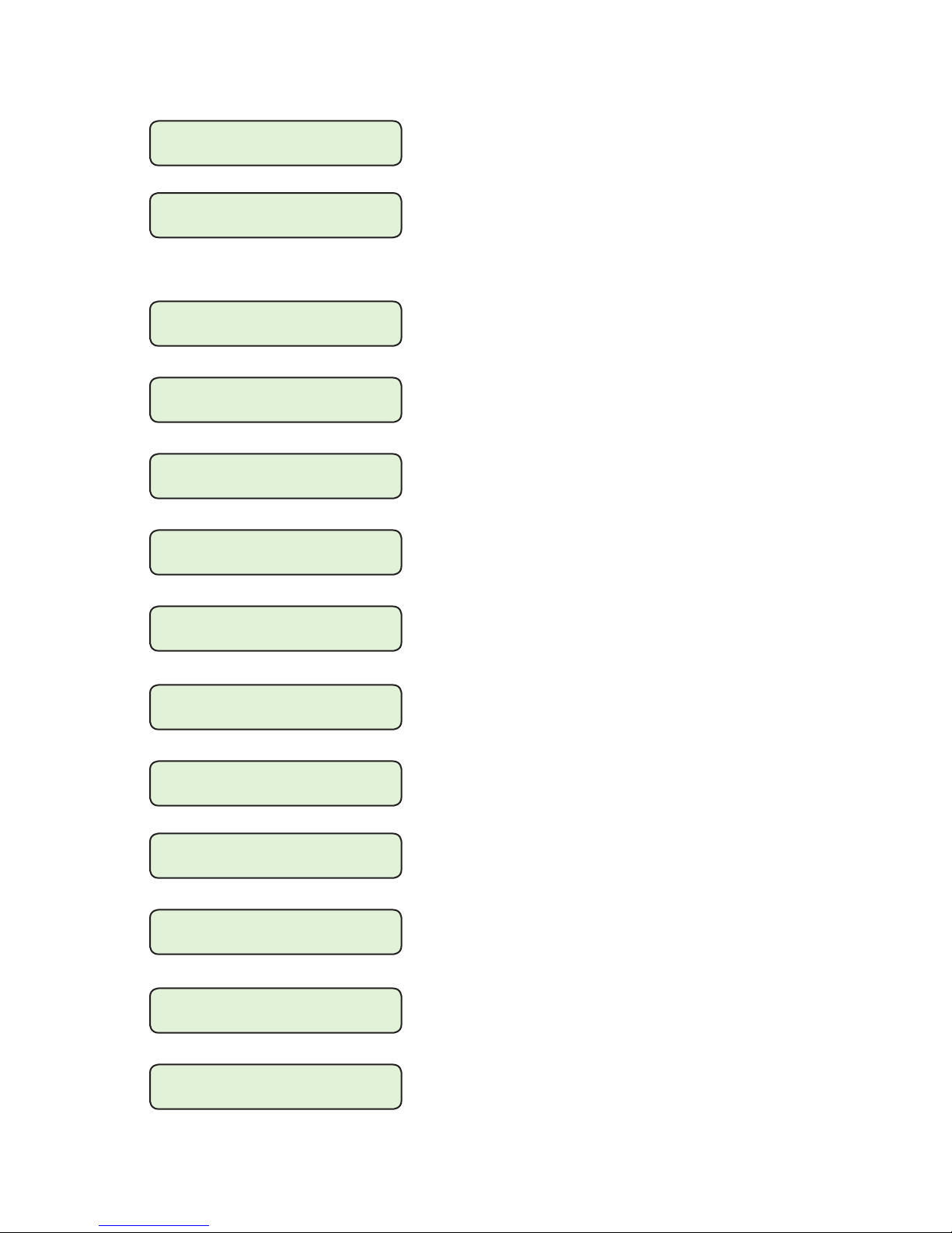
Communication/Ethernet (Cont.'d)
Appendix – A
Auto Negotiation
ENABLE
Keepalive Time
120 sec
Radius Server 1 IP
xx.xx.xx.xxx
Radius Server 2 IP
xx.xx.xx.xxx
Radius 1 Auth. Port
1812
Radius 2 Auth. Port
1814
When enabled allows the user to set the Ethernet Port to a fixed
speed of 100 mbps.
The Keepalive Time feature applies only to the Ethernet
connection. If no communication activity is detected on a
previously open Ethernet socket longer than the timeout setting
the control will close the socket and make it available for
connection. The setting range is from 1 to 50,000 seconds.
Allows the user to enter the IP Address of the Primary Radius
Server.
Allows the user to enter the IP Address of the Secondary
Radius Server.
Allows the primary Radius server Authentication Port ID to be
set.
Allows the secondary Radius server Authentication Port ID to
be set.
Radius 1 Acc. Port
1813
Radius 2 Acc. Port
1815
Radius En./Dis.
disable
IPSEC En./Dis.
diable
SNTP IP Address
xx.xx.xx.xx
SNTP En./Dis.
disable
Allows the primary Radius server Accounting Port ID to be set.
Allows the secondary Radius server Accounting Port ID to be
set.
Allows Radius Cyber Security to be enabled or disabled.
Allows Internet Protocol Security (IPsec) to be enabled or
disabled.
Allows the user to enter the IP Address of the network server.
Enables the SNTP (Simple Network Time protocol) to allow
Network Time Synchronization.
Time Zone GMT
-5 Hr
Figure A-9 Communication Screens (page 4 of 6)
Allows the user to select the Time Zone that the control resides
in.
A–33
Page 65
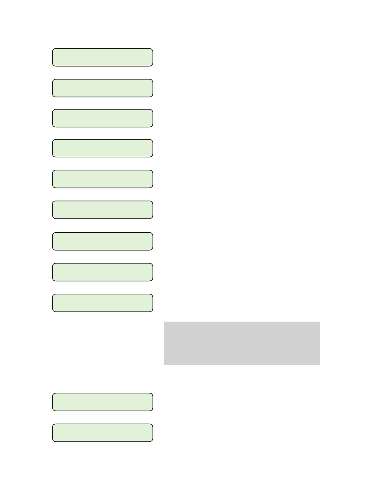
M-6200A Instruction Book
Communication/HMI
Set LCD Contrast: E
User Line 1 E
Beckwith Electric
User Line 2 E
M-6200A
Level 1 Access Code
Press ENT to change
Level 2 Access Code
Press ENT to change
Clear Osc Records
Ready Press ENTER
Allows contrast to be adjusted from +10 (lightest) to –10
(darkest). Factory setting is 0, which provides a neutral contrast.
Allows input of 20 ASCII characters to configure a unit locator or
description. If not configured, a row of 15 asterisks will appear
in top row of User Line #1 screen.
Allows input of 20 ASCII characters to configure a unit locator or
description. If not configured, a row of 15 asterisks will appear
in bottom row of User Line #2 screen.
Configures a six-digit alpha/numerical Access Code for Level 1.
Factory setting is 000000 (disabled).
Configures a six-digit alpha/numerical Access Code for Level 2.
Factory setting is 222222.
Allows the user to clear Oscillograph records from the HMI.
Oscillograph Message
ENABLE
Radius Secret Code
Press ENT to change
IEEE 1686 Standard
not used/Authen with Encryp
Communication/Bluetooth
Bluetooth Enable
ENABLE
Feature enables or disables the OSC Triggered Message to be
scrolled on the unit display when an OSC record is available.
Allows the user to change the Radius Configuration Secret
Code.
Allows the user to enable IEEE 1686 Standard Cyber Security.
This option MUST be enabled in the control to allow User
Name/Password Cyber Security to be implemented.
NOTE:Q Once IEEE 1686 Standard Cyber Security is
enabled, the user must enter a valid User Name
and Password to access any menus other than the
"Utilities/About" menu. This selection cannot be
changed to "not used" without entering a valid User
Name and Password.
Enables or disables the Bluetooth feature when installed on the
control.
Bluetooth Reset
Ready Press ENTER
Figure A-9 Communication Screens (page 5 of 6)
A–34
Allows the user to reset the Bluetooth Module to "Beckwith"
factory default settings.
Page 66
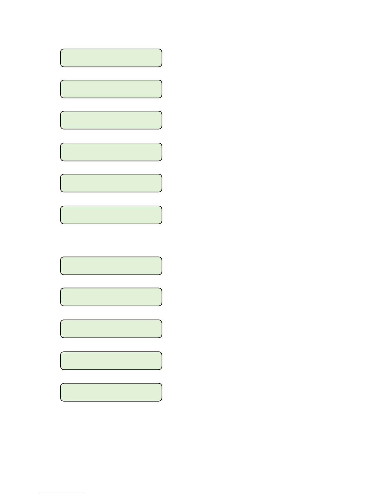
Communication/Bluetooth (Cont'd)
Appendix – A
Bluetooth Protocol
MODBUS
Authentication
disable
Friendly Name
M6200A
Bluetooth Pass Reset
Ready Press ENTER
Control BT Device
XX:XX:XX:XX:XX:XX
Bluetooth Mode
MODE0
Provides the ability to select either MODBUS or DNP3.0
protocol.
Enables or disables Authentication and provides the means to
enter a Pass Key when set (1 to 16 characters).
Allows the user to name the unit (maximum of 32 characters).
The Bluetooth Passkey can be reset to default conditions (no
Passkey and Authentication Disabled) if necessary.
Displays the Bluetooth MAC address of the control.
The Bluetooth mode can be set to Mode0 in which the control is
discoverable and connectable to any client station, or Mode1 in
which the control is non-discoverable but is connectable to any
client station that knows the control Bluetooth device address.
Communication/RS232
Protocol
MODBUS
Baud Rate
115200
Parity
NONE
Stop Bits
ONE STOPBIT
Sync Time
XX mS
Allows selection between standard protocols, DNP3.0,
MODBUS or Cooper 2179.
Selects Baud Rate for the RS232 port.
None, odd or even parity is available.
One or Two Stop Bits are available.
This time delay improves robust operation when communication
lines are intermittent. Communication dead-sync time is the
time that the control will wait from the last received character
and continue without attempting to resynchronize. Factory
setting is 50 msec; range is 0-32000 msec.
Figure A-9 Communication Screens (page 6 of 6)
A–35
Page 67
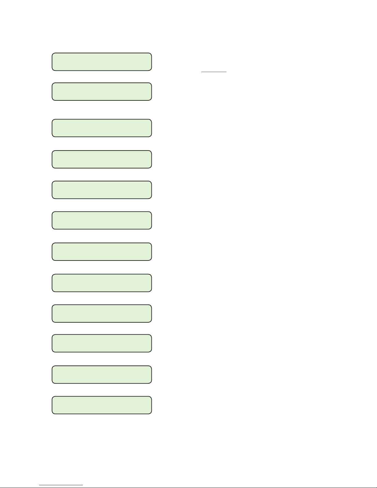
M-6200A Instruction Book
Utilities/Calibration-Test
Bias Voltage
Status/Test Mode
Load Voltage
xxx.x Volts
Volt Cal Coefficient
32767 X
Volt RMS Coefficient
32767 X
Control Load I
x.x mA Lead
Curr Cal Coefficient
32767 X
When ENT is pressed, the control status can be checked, and a
bias test voltage can be entered to test the control’s automatic
operation (see Figure 7-3).
Displays the real-time measured value of voltage at the
regulator or the transformer, including the voltage reduction if
applicable and any corrections made using the user-selected
VT correction voltage.
Voltage calibration factor. Requires Level 3 Access to change.
Voltage RMS calibration factor. Requires Level 3 Access to
change.
Displays the real-time measured value of load current related to
the scaling factor Current Transformer of 200 mA, 1 A or 5A.
Current calibration factor. Requires Level 3 Access to change.
Power Factor
x.xxx Lead
I Sin Coefficient
0 X
I Cos Coefficient
8192 X
Motor Current
x.xx mA
Mtr Cal. Coefficient
8192 X
Mtr Sin Coefficient
0 X
Provides the user with the real-time Power Factor value.
Current Sine Coefficient calibration factor. Requires Level 3
Access to change.
Displays the PF Factor Cosine correction factor as determined
by Autocal. Can also be manually set. However, Beckwith
Electric does not recommend manual setting of this parameter.
Displays the real-time measured value of motor current.
Motor Calibration Coefficient calibration factor. Requires Level
3 Access to change.
Motor Sine Coefficient calibration factor. Requires Level 3
Access to change.
A–36
Figure A-10 Utilities Screens (page 1 of 3)
Page 68
Utilities/Calibration-Test (Cont'd)
Appendix – A
Mtr Cos Coefficient
8192 X
Mtr RMS Coefficient
8192 X
LED Scroll Test
Press ENT to begin
Input Test
Press ENT to Begin
Output Test
Press ENT to test
Button Input Test
Press ENT to Begin
Motor Cosine Coefficient calibration factor. Requires Level 3
Access to change.
Motor RMS Coefficient calibration factor. Requires Level 3
Access to change.
Momentarily illuminates each LED on the control panel. Push
EXIT to stop.
Provides the means to test all external inputs to the control.
Provides the means to test all outputs from the control.
Provides the means to verify proper operation of each front
panel pushbutton from the HMI.
Change Src Input
press ENTER.
Watchdog resets: 0
Total resets: xx
Clear reset counters
Pressing Enter will cause the source side PT voltage to be
measured instead of being calculated. The second line on the
LCD screen will display Measured XXXXX V
Pressing Enter will toggle to the calculated source
side voltage and the second line on the LCD screen
will display Calculated XXXX V
This shows the total number of watchdog resets and total resets
which include Power down and watchdog resets.
This clears Watchdog Resets and Total Resets counters.
Press ENT to begin
X1 Duration
0 ms, Avg: 0 ms
(or Motor Seal-in Pulse)
When the Operation Counter is configured as Motor Seal-In,
When the Operation Counter is configured as X1, the X1 duration
is the instantaneous measure of the X1 pulse generated by the
counter contact switch. It also displays the average X1 pulse
duration over the last 8 tap operations. The user can use this
measurement to set the X mode Delay.
the LCD will then display "Motor Seal-In Pulse" and the values
indicate the instantaneous and the average (over the last 8 tap
operations) duration of the Motor Current Pulse.
Figure A-10 Utilities Screens (page 2 of 3)
A–37
Page 69
M-6200A Instruction Book
Utilities/Calibration-Test (Cont'd)
Comm Options En/Dis
01111111111111
Init Setpoints
Press ENT to begin
Erase Flash Files
Press ENT to begin
For additional Cyber Security, the user may disable specific
communication ports and/or protocols.
Position from Left:
1. http
2. TERMINAL
3. ICMP
4. FTP
5. SD CARD
6. COM2
7. COM1
Key
0 = disabled
1 = ENABLED
Allows a user with "Level 2" or "Manage Users" permission to
initialize setpoints.
Allows a user with "Level 2" or "Manage Users" permission to
erase Flash files when IEEE 1686 is disabled. If IEEE 1686 is
enabled, the control will display "Disable IEEE 1686!".
8. USB
9. RADIUS
10. FXFER
11. MODBUS
12. DNP UDP
13. DNP TCP
14. ETHERNET
Utilities/About
Serial Number
XXXXX
Firmware Version
D-0228Vxx.xx.xx
EE Checksum
XXXXXX
Displays the unit serial number.
Displays the firmware version that is loaded onto the control.
Displays EE Prom Checksum value.
A–38
Figure A-10 Utilities Screens (page 3 of 3)
Page 70

Legal Information
Patent
The units described in this manual are covered by
U.S. Patents, with other patents pending.
Buyer shall hold harmless and indemnify the Seller,
its directors, officers, agents, and employees from
any and all costs and expense, damage or loss,
resulting from any alleged infringementof United
States Letters Patent or rights accruing thereform or
trademarks, whether federal, state, or common law,
arising from the Seller’s compliance with Buyer’s
designs, specifications, or instructions.
Warranty
Seller hereby warrants that the goods which are the
subject matter of this contract will be manufactured
in a good workmanlike manner and all materials
used herein will be new and reasonably suitable for
the equipment. Seller warrants that if, during a
period of ten years from date of shipment of the
equipment, the equipment rendered shall be found
by the Buyer to be faulty or shall fail to peform in
accordance with Seller’s specifications of the
product, Seller shall at his expense correct the
same, provided, however, that Buyers shall ship the
equipment prepaid to Seller’s facility. The Seller’s
responsibility hereunder shall be limited to replacement value of the equipment furnished under this
contract.
Seller makes no warranties expressed or implied
other than those set out above. Seller specifically
excludes the implied warranties of merchantibility
and fitness for a particular purpose. There are no
warranties which extend beyond the description
contained herein. In no event shall Seller be liable for
consequential, exemplary, or punitive damages of
whatever nature.
Any equipment returned for repair must be sent
with transportation charges prepaid. The equipment
must remain the property of the Buyer. The aforementioned warranties are void if the value of the
unit is invoiced to the Seller at the time of return.
Indemnification
The Seller shall not be liable for any property
damages whatsoever or for any loss or damage
arising out of, connected with, or resulting from
this contract, or from the performance or breach
thereof, or from all services covered by or furnished
under this contract.
In no event shall the Seller be liable for special,
incidental, exemplary, or consequential damages,
including but not limited to, loss of profits or
revenue, loss of use of the equipment or any
associated equipment, cost of capital, cost of
purchased power, cost of substitute equipment,
facilities or services, downtime costs, or claims or
damages of customers or employees of the Buyer
for such damages, regardless of whether said claim
or damages is based on contract, warranty, tort
including negligence, or otherwise.
Under no circumstances shall the Seller be liable
for any personal injury whatsoever.
It is agreed that when the equipment furnished
hereunder are to be used or performed in connection with any nuclear installation, facility, or
activity, Seller shall have no liability for any
nuclear damage, personal injury, property damage,
or nuclear contamination to any property located at
or near the site of the nuclear facility. Buyer agrees
to indemnify and hold harmless the Seller against
any and all liability associated therewith whatsoever whether based on contract, tort, or otherwise.
Nuclear installation or facility means any nuclear
reactor and includes the site on which any of the
foregoing is located, all operations conducted on
such site, and all premises used for such operations.
Notice:
Any illustrations and descriptions by Beckwith
Electric Co., Inc. are for the sole purpose of
identification.
The drawings and/or specifications enclosed herein
are the proprietary property of Beckwith Electric
Co., Inc., and are issued in strict confidence;
therefore, shall not be used as a basis of reproduction of the apparatus described therein without
written permission of Beckwith Electric Co., Inc.
No illustration or description contained herein
shall be construed as an express warranty of
affirmation, promise, description, or sample, and
any and all such express warranties are specifically
excluded nor shall such illustration or description
imply a warranty that the product is merchantable
or fit for a particular purpose. There shall be no
warranties which extend beyond those contained in
the Beckwith Electric Co., Inc. terms of sale.
All rights reserved by Beckwith Electric Co., Inc. No reproduction may be made without prior written approval
of the Company.
Page 71

This Page Left Intentionally Blank
Page 72

BECKWITH ELECTRIC CO., INC.
6190 ‑ 118th Avenue North • Largo, Florida 33773‑3724 U.S.A.
PHONE (727) 544‑2326 • FAX (727) 546‑0121
www.beckwithelectric.com
ISO 9001:2008
© 2010 Beckwith Electric Co. All Rights Reserved.
Printed in USA
800‑B‑2355‑AG‑05 04
/17
 Loading...