

Page 1
Instruction Book
Part 1 of 2
M-3425A
Generator Protection
Page 2
PROTECTION
Generator Protection
M-3425A
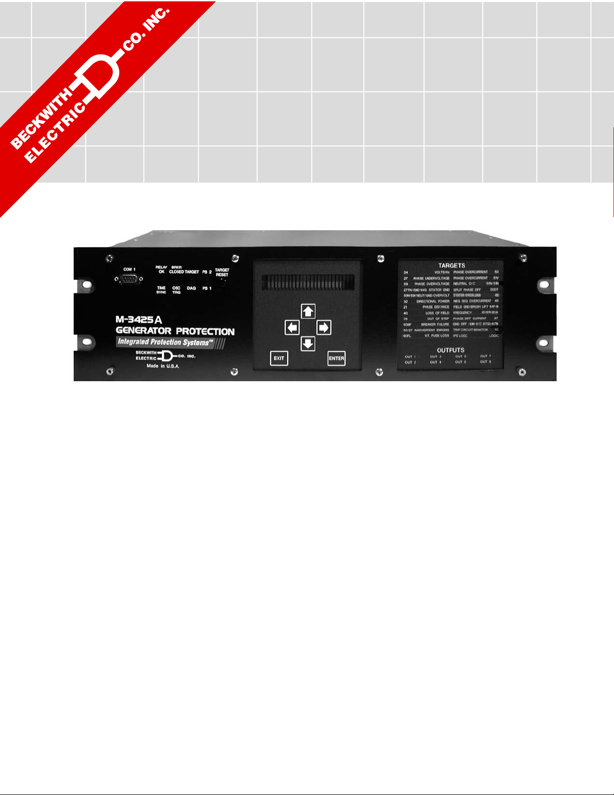
Integrated Protection System® for Generators of All Sizes
Unit shown with optional M-3925A Target Module and M-3931
HMI (Human-Machine Interface) Module.
• Exceeds IEEE C37.102 and Standard 242 requirements for generator
protection
• Protects generators of any prime mover, grounding and connection type
• Provides all major protective functions for generator protection including
Out-of-Step (78), Split-Phase Differential (50DT), Under Frequency Time
Accumulation (81A), Inadvertent Energizing (50/27) and Turn-to-Turn Fault
(59X)
®
• Expanded IPScom
setting and programming, including logic schemes
• Simple application with Base and Comprehensive protection packages
• Load encroachment blinders and power swing blocking for system backup
protection (21) to enchance security during system abnormal conditions
Communications Software provides simple and logical
• Options: Ethernet Connection, Field Ground/Brush Lift-Off Protection (64F/B),
Sync Check (25), 100% Stator Ground Fault Protection by low frequency
injection (64S) and Expanded I/O (15 additional Output Contacts and 8
additional Control/Status Inputs)
Page 3

M-3425A Generator Protection Relay
Protective Functions
Base Package
• Overexcitation (V/Hz) (24)
• Phase Undervoltage (27)
• Directional power sensitive triple-setpoint Reverse Power, Low Forward Power or Overpower detection, one of which can be used for
sequential tripping (32)
• Dual-zone, offset-mho Loss of Field (40), which
may be applied with undervoltage controlled
accelerated tripping
• Sensitive Negative Sequence Overcurrent protection and alarm (46)
• Instantaneous Phase Overcurrent (50)
• Inadvertent Energizing (50/27)
• Generator Breaker Failure (50BF)
• Instantaneous Neutral Overcurrent (50N)
• Inverse Time Neutral Overcurrent (51N)
• Three-phase Inverse Time Overcurrent
(51V) with voltage control and voltage restraint.
• Phase Overvoltage (59)
• Neutral Overvoltage (59N)
• Multi-purpose Overvoltage (59X)
• VT Fuse-Loss Detection and blocking
(60FL)
• Residual Directional Overcurrent (67N)
• Four-step Over/Underfrequency (81)
• Phase Differential Current (87)
• Ground (zero sequence) Differential Current
(87GD)
• IPSlogicTM takes the contact input status and
function status and generates outputs by
employing (OR, AND, and NOT) boolean
logic and a timer.
Protective Functions
Comprehensive Package
The Comprehensive Package includes all Base
Package functions, as well as the following:
• Three-zone Phase Distance protection for
phase fault backup protection (21). Zone three
can be used for Out-of-Step Blocking. Load
encroachment blinders can be applied.
• 100% Stator Ground Fault protection using Third
Harmonic Neutral Undervoltage (27TN) or (59D)
Third Harmonic Voltage Differential (ratio)
• Stator Overload (49) (Positive Sequence
Overcurrent)
• Definite Time Overcurrent (50DT) can be used
for split phase differential
• Out-of-Step (78)
• UnderFrequency Accumulation (81A)
• Rate of Change of Frequency (81R)
Optional Protective Functions
• Sync Check with Phase Angle, ΔV and ΔF
with dead line/dead bus options (25)
• Field Ground (64F) and Brush Lift Off (64B)
(Includes M-3921 Field Ground Coupler)
• 100% Stator Ground protection by low frequency injection (64S). The following equipment is supplied with the 64S option:
– 20 Hz signal generator (430-00426)
– Band-pass Filter (430-00429)
Standard Features
• Eight programmable outputs and six programmable inputs
• Oscillographic recording with COMTRADE
or BECO format
• Time-stamped target storage for 32 events
• Metering of all measured parameters and
calculated values
• Three communications ports (two RS-232
and one RS-485)
• M-3820D IPScom® Communications Software
• Includes MODBUS and BECO 2200
protocols
• Standard 19" rack-mount design (vertical
mounting available)
• Removable printed circuit board and power
supply
• 50 and 60 Hz models available
• Both 1A and 5 A rated CT inputs available
• Additional trip inputs for externally connected
devices
• IRIG-B time synchronization
• Operating Temperature: –20° C to +70° C
• Sequence of Events Log
• Trip Circuit Monitoring
• Breaker Monitoring
• Four Setpoint Groups
Optional Features
• Redundant power supply
• M-3925A Target Module
• M-3931 Human-Machine Interface (HMI)
Module
• RJ45 Ethernet port utilizing MODBUS over
TCP/IP and BECO2200 over TCP/IP protocols
• M-3801D IPSplot®
sis Software
• Expanded I/O (15 additional outputs and 8
additional inputs)
PLUS
Oscillograph Analy-
–2–
Page 4

PROTECTIVE FUNCTIONS
M-3425A Generator Protection Relay
Device Setpoint
Number Function Ranges Increment Accuracy
†
Phase Distance (three-zone mho characteristic)
Circle Diameter #1,#2,#3 0.1 to 100.0 Ω 0.1 Ω 0.1 Ω or 5%
(0.5 to 500.0 Ω)(0.5 Ω or 5%)
Offset #1,#2,#3 –100.0 to 100.0 Ω 0.1 Ω 0.1 Ω or 5%
21
(–500.0 to 500.0 Ω)(0.5 Ω or 5%)
Impedance Angle #1,#2,#3 0° to 90° 1° 1°
Load Encroachment Blinder #1,#2,#3
Angle 1° to 90° 1° 1°
R Reach 0.1 to 100 Ω
Time Delay #1,#2,#3 1 to 8160 Cycles 1 Cycle 1 Cycle or 1%
Out-of-Step Delay 1 to 8160 Cycles 1 Cycle 1 Cycle or 1%
Overcurrent Supervision 0.1 to 20 A 0.1 A 0.1 A or 2%
(0.02 to 4 A) 0.01 A 0.02 A or 2%
When out-of-step blocking on Zone 1 or Zone 2 is enabled, Zone 3 will not trip and it will be used to detect the
out-of-step condition for blocking Function 21 #1 and/or 21 #2.
Volts / Hz
Definite Time
Pickup #1, #2 100 to 200% 1% 1%
Time Delay #1, #2 30 to 8160 Cycles 1 Cycle 25 Cycles
24
Inverse Time
Pickup 100 to 200% 1% 1%
Characteristic Curves Inverse Time #1–#4 — —
Time Dial: Curve #1 1 to 100 1
Time Dial: Curves #2–#4 0.0 to 9.0 0.1
Reset Rate 1 to 999 Sec. 1 Sec. .02 Sec. or 1%
(from threshold of trip)
The percent pickup is based on nominal VT secondary voltage and nominal system frequency settings. The
pickup accuracy stated is only applicable from 10 to 80 Hz, 0 to 180 V, 100 to 150% V/Hz and a nominal voltage
setting of 120 V.
Phase Undervoltage
27
Pickup #1, #2, #3 5 to 180 V 1 V 0.5 V or 0.5%
Time Delay #1, #2, #3 1 to 8160 Cycles 1 Cycle 1 Cycle or 0.5%**
* When both RMS and Line-Ground to Line-Line VT connection is selected.
**When RMS (total waveform) is selected, timing accuracy is
†
Select the greater of these accuracy values.
Values in parentheses apply to 1 A CT secondary rating.
–3–
O
20 cycles or 1%.
0.8 V or 0.75%*
Page 5

M-3425A Generator Protection Relay
PROTECTIVE FUNCTIONS (
Device Setpoint
Number Function Ranges Increment Accuracy
cont
.)
Third-Harmonic Undervoltage, Neutral
Pickup #1, #2 0.10 to 14.00 V 0.01 V 0.1 V or 1%
Positive Sequence
Voltage Block 5 to 180 V 1 V 0.5 V or 0.5%
Forward Under Power Block 0.01 to 1.00 PU 0.01 PU 0.01 PU or 2%
Reverse Under Power Block –1.00 to –0.01 PU 0.01 PU 0.01 PU or 2%
27
TN
Lead Under var Block –1.00 to –0.01 PU 0.01 PU 0.01 PU or 2%
Lag Under var Block 0.01 to 1.00 PU 0.01 PU 0.01 PU or 2%
Lead Power Factor Block 0.01 to 1.00 0.01 0.03 PU or 3%
Lag Power Factor Block 0.01 to 1.00 0.01 0.03 PU or 3%
High Band Forward
Power Block 0.01 to 1.00 PU 0.01 PU 0.01 PU or 2%
Low Band Forward
Power Block 0.01 to 1.00 PU 0.01 PU 0.01 PU or 2%
Time Delay #1, #2 1 to 8160 Cycles 1 Cycle 1 Cycle or 1%
Directional Power
†
32
Pickup #1, #2, #3 –3.000 to +3.000 PU 0.001 PU 0.002 PU or 2%
Time Delay #1, #2, #3 1 to 8160 Cycles 1 Cycle +16 Cycles or 1%
The minimum Pickup limits are –.002 and +.002 respectively.
The per-unit pickup is based on nominal VT secondary voltage and nominal CT secondary current settings. This
function can be selected as either overpower or underpower in the forward direction (positive setting) or reverse
direction (negative setting). Element #3 can be set as real power or reactive power. This function includes a
programmable target LED that may be disabled.
Loss of Field (dual-zone offset-mho characteristic)
Circle Diameter #1, #2 0.1 to 100.0 Ω 0.1 Ω 0.1 Ω or 5%
Offset #1, #2 –50.0 to 50.0 Ω 0.1 Ω 0.1 Ω or 5%
40
Time Delay #1, #2 1 to 8160 Cycles 1 Cycle 1 Cycle or 1%
Time Delay with
Voltage Control #1, #2 1 to 8160 Cycles 1 Cycle 1 Cycle or 1%
Voltage Control 5 to 180 V 1 V 0.5 V or 0.5%
(positive sequence)
Directional Element 0° to 20° 1° —
(0.5 to 500.0 Ω)(0.5 Ω or 5%)
(–250.0 to 250.0 Ω)(0.5 Ω or 5%)
Time delay with voltage control for each zone can be individually enabled.
†
Select the greater of these accuracy values.
Values in parentheses apply to 1 A CT secondary rating.
–4–
Page 6

M-3425A Generator Protection Relay
PROTECTIVE FUNCTIONS (
Device Setpoint
Number Function Ranges Increment Accuracy
cont
.)
Negative Sequence Overcurrent
Definite Time
Pickup 3 to 100% 1% 0.5% of 5 A
(0.5% of 1 A)
Time Delay 1 to 8160 Cycles 1 Cycle 1 Cycle or 1%
Inverse Time
Pickup 3 to 100% 1% 0.5 % of 5 A
46
Time Dial Setting 1 to 95 1 3 Cycles or 3%
2
t)
(K= I
2
(0.5% of 1 A)
Definite Maximum
Time to Trip 600 to 65,500 Cycles 1 Cycle 1 Cycle or 1%
Definite Minimum Time 12 Cycles — fixed
Reset Time (Linear) 1 to 600 Seconds 1 Second —
(from threshold of trip)
Pickup is based on the generator nominal current setting.
Stator Overload Protection
Time Constant #1, #2 1.0 to 999.9 minutes 0.1 minutes
49
Maximum Overload Current 1.00 to 10.00 A 0.01 A 0.1 A or 2%
(0.20 to 2.00 A)
†
Instantaneous Phase Overcurrent
Pickup #1, #2 0.1 to 240.0 A 0.1 A 0.1 A or 3%
50
(0.1 to 48.0 A) (0.02 A or 3%)
Time Delay #1, #2 1 to 8160 Cycles 1 Cycle 1 Cycle or 1%
When frequency f is < (f
–5 ) Hz add an additional time of (1.5/f + 0.033) sec to the time delay accuracy.
nom
Breaker Failure
Pickup
50
Phase Current 0.10 to 10.00 A 0.01 A 0.1 A or 2%
50
BF
BF-Ph
50
Neutral Current 0.10 to 10.00 A 0.01 A 0.1 A or 2%
BF-N
(0.02 to 2.00 A) (0.02 A or 2%)
(0.02 to 2.00 A) (0.02 A or 2%)
Time Delay 1 to 8160 Cycles 1 Cycle 1 Cycle or 1%
50BF can be initiated from designated M-3425A output contacts or programmable control/status inputs.
Definite Time Overcurrent
Pickup Phase A #1, #2 0.20 A to 240.00 A 0.01 A 0.1 A or 3%
50
DT
Pickup Phase B #1, #2 (same as above)
(0.04 A to 48.00 A) (0.02 A or 3%)
Pickup Phase C #1, #2 (same as above)
Time Delay #1, #2 1 to 8160 Cycles 1 Cycle 1 Cycle or 1%
This function uses generator line-side currents.
When 50DT function is used for split-phase differential protection, 50BF, 87, and 87GD functions should not be
used, and the I
†
Select the greater of these accuracy values.
, IB and IC inputs must be connected to the split phase differential currents.
A
Values in parentheses apply to 1 A CT secondary rating.
–5–
Page 7

M-3425A Generator Protection Relay
PROTECTIVE FUNCTIONS (
Device Setpoint
Number Function Ranges Increment Accuracy
cont
.)
Instantaneous Neutral Overcurrent
Pickup 0.1 to 240.0 A 0.1 A 0.1 A or 3%
50N
(0.1 to 48.0 A) (0.02 A or 3%)
Time Delay 1 to 8160 Cycles 1 Cycle 1 Cycle or 1%
When the frequency f is < (f
–5) Hz add an additional time of (1.5/f + 0.033) sec to the time delay accuracy.
nom
Inadvertent Energizing
Overcurrent
50
Pickup 0.5 to 15.00 A 0.01 A 0.1 A or 2%
50/
(0.1 to 3.00 A) (0.02 A or 2%)
27
Undervoltage
27
Pickup 5 to 130 V 1 V 0.5 V
Pick-up Time Delay 1 to 8160 Cycles 1 Cycle 1 Cycle or 1%
Drop-out Time Delay 1 to 8160 Cycles 1 Cycle 1 Cycle or 1%
Inverse Time Neutral Overcurrent
Pickup 0.25 to 12.00 A 0.01 A 0.1 A or 1%
51N
Characteristic Curve Definite Time/Inverse/Very Inverse/Extremely Inverse/IEC Curves
Time Dial 0.5 to 11.0 0.1 3 Cycles or 3%*
* For IEC Curves the timing accuracy is 5%.
When the frequency f is < (f
–5 )Hz add an additional time of (1.5/f + 0.033) sec to the time delay accuracy.
nom
Inverse Time Phase Overcurrent, with Voltage Control or Voltage Restraint
(0.05 to 2.40 A) (0.02 A or 1%)
Moderately Inverse/Very Inverse/Extremely Inverse/IEEE Curves
0.05 to 1.10 (IEC curves) 0.01
0.85 to 1.15 (IEEE curves) 0.01
†
Pickup 0.50 to 12.00 A 0.01 A 0.1 A or 1%
(0.10 to 2.40 A) (0.02 A or 1%)
Characteristic Curve Definite Time/Inverse/Very Inverse/Extremely Inverse/IEC Curves
51V
Moderately Inverse/Very Inverse/Extremely Inverse/IEEE Curves
Time Dial 0.5 to 11.0 0.1 3 Cycles or 3%*
0.05 to 1.10 (IEC curves) 0.01
0.85 to 1.15 (IEEE curves) 0.01
Voltage Control (VC) 5 to 180 V 1 V 0.5 V or 0.5%
or
Voltage Restraint (VR) Linear Restraint ——
* For IEC Curves the timing accuracy is 5%.
†
Select the greater of these accuracy values.
Values in parentheses apply to 1 A CT secondary rating.
–6–
Page 8

M-3425A Generator Protection Relay
PROTECTIVE FUNCTIONS (
Device Setpoint
Number Function Ranges Increment Accuracy
cont
.)
†
Phase Overvoltage
59
Pickup #1, #2, #3 5 to 180 V 1 V 0.5 V or 0.5%
0.8 V or 0.75%*
Time Delay #1, #2, #3 1 to 8160 Cycles 1 Cycle 1 Cycle or 1%**
Input Voltage Select Phase or Positive Sequence***
* When both RMS and Line-Ground to Line-Line is selected.
** When RMS (total waveform) is selected, timing accuracy is +20 cycles or
1%.
*** When positive sequence voltage is selected, the 59 Function uses discrete Fourier transform (DFT) for
magnitude calculation, irrespective of the RMS/DFT selection, and timing accuracy is
1 Cycle or 1%.
Third-Harmonic Voltage Differential Ratio
Ratio (Vx/VN) 0.1 to 5.0 0.1
59D
Time Delay 1 to 8160 Cycles 1 Cycle 1 Cycle or 1%
Positive Seq Voltage Block 5 to 180 V 1 V 0.5 V or 0.5%
Line Side Voltage V
or 3V0 (calculated)
X
The 59D function with VX cannot be enabled if the 25 function is enabled. The line side voltage can be selected as
the third harmonic of 3V
3V
selection for line side voltage can only be used with line-ground VT configuration.
0
(equivalent to VA + VB + VC) or VX.
0
Neutral Overvoltage
Pickup #1, #2, #3 5.0 to 180.0 V 0.1 V 0.5 V or 0.5%
59N
Time Delay #1, #2, #3 1 to 8160 Cycles 1 Cycle 1 Cycle or 1%
When 64S is purchased, the 59N Time Delay Accuracy is –1 to +5 cycles.
Multi-purpose Overvoltage
Pickup #1, #2 5.0 to 180.0 V 0.1 V 0.5 V or 0.5%
59X
Time Delay #1, #2 1 to 8160 Cycles 1 Cycle 1 Cycle or 1%
Multi-purpose input that may be used for turn-to-turn stator ground protection, bus ground protection, or as an
extra Phase-Phase, or Phase-Ground voltage input.
VT Fuse-Loss Detection
A VT fuse-loss condition is detected by using the positive and negative sequence components
60
of the voltages and currents. VT fuse-loss output can be initiated from internally generated
logic, and/or from input contacts.
FL
Alarm Time Delay 1 to 8160 Cycles 1 Cycle 1 Cycle or 1%
Three Phase VT
Fuse Loss Detection Enable/Disable
†
Select the greater of these accuracy values.
Values in parentheses apply to 1 A CT secondary rating.
–7–
Page 9

M-3425A Generator Protection Relay
PROTECTIVE FUNCTIONS (
Device Setpoint
Number Function Ranges Increment Accuracy
cont
.)
Residual Directional Overcurrent
Definite Time*
Pickup 0.5 to 240.0 A 0.1 A 0.1 A or 3%
(0.1 to 48.0 A) (0.02 A or 3%)
Time Delay 1 to 8160 Cycles 1 Cycle –1 to +3 Cycles or 1%
Inverse Time*
67N
Pickup 0.25 to 12.00 A 0.01 A 0.1 A or 3%
(0.05 to 2.40 A) (0.02 A or 3%)
Characteristic Curve Definite Time/Inverse/Very Inverse/Extremely Inverse/IEC Curves
Moderately Inverse/Very Inverse/Extremely Inverse/IEEE Curves
Time Dial 0.5 to 11.0 0.1 3 Cycles or 5%
0.05 to 1.10 (IEC Curves) 0.01
0.5 to 11 (IEEE curves) 0.01
Directional Element
Max Sensitivity Angle (MSA) 0 to 359° 1°
Polarizing Quantity 3V
(calculated), VN or V
o
X
*Directional control for 67NDT or 67NIT may be disabled.
V
polarization cannot be used if 25 function is enabled.
X
3V
polarization can only be used with line-ground VT configuration.
o
Operating current for 67N can be selected as 3
I
If 87GD is enabled, 67N with
(Residual CT) operating current will not be available.
N
I
(calculated) or
o
I
(Residual CT).
N
Out of Step (mho characteristic)
†
Circle Diameter 0.1 to 100.0 Ω 0.1 Ω 0.1 Ω or 5%
(0.5 to 500.0 Ω)(0.5 Ω or 5%)
Offset –100.0 to 100.0 Ω 0.1 Ω 0.1 Ω or 5%
(–500.0 to 500.0 Ω)(0.5 Ω or 5%)
Impedance Angle 0° to 90° 1° 1°
78
Blinder 0.1 to 50.0 Ω 0.1 Ω 0.1 Ω or 5%
(0.5 to 250.0 Ω)(0.5 Ω or 5%)
Time Delay 1 to 8160 Cycles 1 Cycle 1 Cycle or 1%
Trip on mho Exit Enable/Disable
Pole Slip Counter 1 to 20 1
Pole Slip Reset 1 to 8160 Cycles 1 Cycle 1 Cycle or 1%
Frequency
Pickup #1,#2,#3,#4 50.00 to 67.00 Hz 0.01 Hz 0.02 Hz
40.00 to 57.00 Hz*
81
Time Delay #1–#4 3 to 65,500 Cycles 1 Cycle 2 Cycles or 1%
The pickup accuracy applies to 60 Hz models at a range of 57 to 63 Hz, and to 50 Hz models at a range of 47 to
53 Hz. Beyond these ranges, the accuracy is
0.1 Hz.
* This range applies to 50 Hz nominal frequency models.
†
Select the greater of these accuracy values.
Values in parentheses apply to 1 A CT secondary rating.
–8–
Page 10

M-3425A Generator Protection Relay
PROTECTIVE FUNCTIONS (
Device Setpoint
Number Function Ranges Increment Accuracy
Frequency AccumulationFrequency Accumulation
Frequency Accumulation
Frequency AccumulationFrequency Accumulation
cont
.)
†
Bands #1, #2, #3, #4, #5, #6
High Band #1 50.00 to 67.00 Hz 0.01 Hz 0.02 Hz
81A
40.00 to 57.00 Hz*
Low Band #1–#6 50.00 to 67.00 Hz 0.01 Hz 0.02 Hz
40.00 to 57.00 Hz*
Delay #1–#6 3 to 360,000 Cycles 1 Cycle 2 Cycles or 1%
When using multiple frequency bands, the lower limit of the previous band becomes the upper limit for the next band,
i.e., Low Band #2 is the upper limit for Band #3, and so forth. Frequency bands must be used in sequential order, 1 to 6.
Band #1 must be enabled to use Bands #2–#6. If any band is disabled, all following bands are disabled.
When frequency is within an enabled band limit, accumulation time starts (there is an internal ten cycle delay prior to
accumulation) and allows the underfrequency blade resonance to be established to avoid unnecessary accumulation of
time. When duration is greater than set delay, the alarm asserts and a target log entry is made.
The pickup accuracy applies to 60 Hz models at a range of 57 to 63 Hz, and 50 Hz models at a range of 47 to 53 Hz.
Beyond these ranges, the accuracy is
* This range applies to 50 Hz nominal frequency models.
0.1 Hz.
Rate of Change of Frequency
Pickup #1, #2 0.10 to 20.00 Hz/Sec. 0.01 Hz/Sec. 0.05 Hz/Sec. or 5%
81R
Time Delay #1, #2 3 to 8160 Cycles 1 Cycle + 20 Cycles
Negative Sequence
Voltage Inhibit 0 to 99% 1% 0.5%
Phase Differential Current
Pickup #1, #2 0.20 A to 3.00 A 0.01 A 0.1 A or 5%
(0.04 to 0.60 A) (0.02 A or 5%)
87
Percent Slope #1, #2 1 to 100% 1% 2%
Time Delay* #1, #2 1 to 8160 Cycles 1 Cycle 1 Cycle or 1%
CT Correction** 0.50 to 2.00 0.01
*When a time delay of 1 cycle is selected, the response time is less than 1–1/2 cycles.
**The CT Correction factor is multiplied by
I
,
I
,
I
A
B
C.
Ground (zero sequence) Differential Current
Pickup 0.20 to 10.00 A 0.01 A 0.1 A or 5%
87
GD
Time Delay 1 to 8160 Cycles 1 Cycle 1 Cycle or 1%
CT Ratio Correction (R
(0.04 to 2.00 A) (0.02 A or 5%)
) 0.10 to 7.99 0.01
C
The 87GD function is provided primarily for low-impedance grounded generator applications. This function
I
or
I
operates as a directional differential. If 3
becomes non-directional.
If 67N function with
split-phase differential, 87GD function will not be available.
I
(Residual) operating current is enabled, 87GD will not be available. Also, if 50DT is used for
N
is extremely small (less than 0.2 secondary Amps), the element
0
n
†
Select the greater of these accuracy values.
Values in parentheses apply to 1 A CT secondary rating.
–9–
Page 11

M-3425A Generator Protection Relay
PROTECTIVE FUNCTIONS (
Device Setpoint
Number Function Ranges Increment Accuracy
IPSlogic
TM
cont
.)
†
IPSlogic uses element pickups, element trip commands, control/status input state changes,
IPS
output contact close signals to develop 6 programmable logic schemes.
Time Delay #1–#6 1 to 8160 Cycles 1 Cycle 1 Cycle or 1%
Breaker Monitoring
BM
Pickup 0 to 50,000 kA Cycles 1 kA Cycles 1 kACycles
Time Delay 0.1 to 4095.9 Cycles 0.1 Cycles 1 Cycle or 1%
2
or kA
Cycles or kA2 Cycles or kA2 Cycles
Timing Method IT or I2T
Preset Accumulators 0 to 50,000 kA Cycles 1 kA Cycle
Phase A, B, C
The Breaker Monitor feature calculates an estimate of the per-phase wear on the breaker contacts by measuring and
integrating the current (or current squared) through the breaker contacts as an arc.
The per-phase values are added to an accumulated total for each phase, and then compared to a user-programmed
threshhold value. When the threshhold is exceeded in any phase, the relay can set a programmable output contact.
The accumulated value for each phase can be displayed.
The Breaker Monitoring feature requires an initiating contact to begin accumulation, and the accumulation begins after
the set time delay.
Trip Circuit Monitoring
TC
Time Delay 1 to 8160 Cycles 1 Cycle 1 Cycle or 1%
The AUX input is provided for monitoring the integrity of the trip circuit. This input can be used for nominal trip coil
voltages of 24 V dc, 48 V dc, 125 V dc and 250 V dc.
Nominal Settings
Nominal Voltage 50.0 to 140.0 V 0.1 V —
Nominal Current 0.50 to 6.00 A 0.01 A —
VT Configuration Line-Line/Line-Ground/
Line-Ground to Line-Line*
Delta/Wye Unit
Transformer Disable/Delta AB/Delta AC
Seal-In Delay 2 to 8160 Cycles 1 Cycle 1 Cycle or 1%
*When Line-Ground to Line-Line is selected, the relay internally calculates the line-line voltages from the line-ground
voltages for all voltage-sensitive functions. This Line-Ground to Line-Line selection should only be used for a VT
connected Line-Ground with a secondary voltage of 69 V (not 120 V).
†
Select the greater of these accuracy values.
Values in parentheses apply to 1 A CT secondary rating.
–10–
Page 12
M-3425A Generator Protection Relay
OPTIONAL PROTECTIVE FUNCTIONS
Device Setpoint
Number Function Ranges Increment Accuracy
Sync Check
25D
Dead Check
Dead Voltage Limit 0 to 60 V 1 V 0.5 V or ±0.5%
Dead Time Delay 1 to 8160 Cycles 1 Cycle –1 to +3 Cycles or 1%
25S
Sync Check
Phase Angle Window 0° to 90° 1° 1°
25
Upper Voltage Limit 60 to 140 V 1 V 0.5 V or ±0.5%
Lower Voltage Limit 40 to 120 V 1 V 0.5 V or ±0.5%
Delta Voltage Limit 1.0 to 50.0 V 0.1 V 0.5 V or ±0.5%
Delta Frequency Limit 0.001 to 0.500 Hz 0.001 Hz 0.0007 Hz or ±5%
Sync Check Time Delay 1 to 8160 Cycles 1 Cycle –1 to +3 Cycles or ±1%
Various combinations of input supervised hot/dead closing schemes may be selected. The 25 function cannot be
enabled if the 59D function with V
or 67N function with VX is enabled.
X
Field Ground Protection
Pickup #1, #2 5 to 100 KΩ 1 KΩ 10% or ±1KΩ
64F
Time Delay #1, #2 1 to 8160 Cycles 1 Cycle (
2
+1) Sec.
IF
Injection Frequency (IF) 0.10 to 1.00 Hz 0.01 Hz
64B
Brush Lift-Off Detection (measuring control circuit)
Pickup 0 to 5000 mV 1 mV
Time Delay 1 to 8160 Cycles 1 Cycle (
2
+1) Sec.
IF
When 64F is purchased, an external Coupler Module (M-3921) is provided for isolation from dc field voltages.
Figure 8, Field Ground Protection Block Diagram, illustrates a typical connection utilizing the M-3921 Field
Ground Coupler. Hardware dimensional and mounting information is shown in Figure 9, M-3921 Field Ground
Coupler Mounting Dimensions.
†
100% Stator Ground Protection by low frequency injection
Pickup 2 to 40 mA 1 mA 1 mA
64S
Time Delay 1 to 8160 Cycles 1 Cycle 1 Cycle* or 1%
Undervoltage Inhibit 5 to 30 V 1 V 0.5 V to 0.5%
External low frequency generator, band pass filter and current transformer are required for this function. 59D and
27TN function should be disabled when the 64S function is enabled. 59N may be applied when this function is
enabled.
* Time Delay accuracy in cycles is based on 20 Hz frequency.
†
Select the greater of these accuracy values.
Values in parentheses apply to 1 A CT secondary rating.
–11–
Page 13

M-3425A Generator Protection Relay
Description
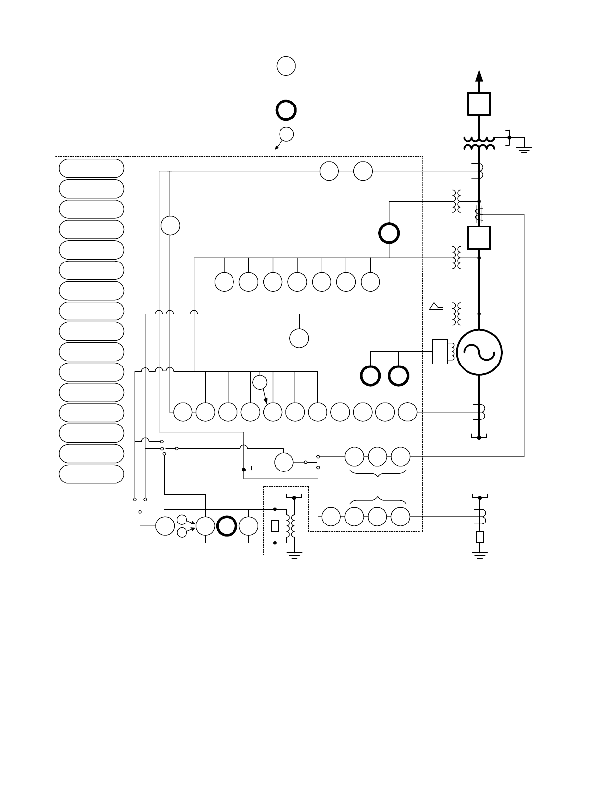
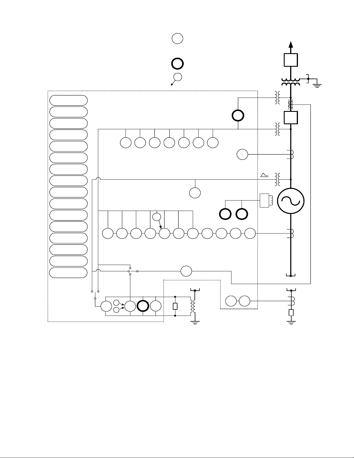
The M-3425A Generator Protection Relay is suitable for all generator ratings and prime movers. Typical
connection diagrams are illustrated in Figure 4, M-3425A One-Line Functional Diagram (configured for phase
differential), and Figure 5, One-Line Functional Diagram (configured for split-phase differential).
Configuration Options
The M-3425A Generator Protection Relay is available in either a Base or Comprehensive package of
protective functions. This provides the user with flexibility in selecting a protective system to best suit the
application. Additional Optional Protective Functions may be added at the time of purchase at per-function
pricing.
The Human-Machine Interface (HMI) Module, Target Module, or redundant power supply can be selected at
time of purchase.
When the Field Ground (64F) Premium Protective Function is purchased, an external coupler module
(M-3921) is provided for isolation from the dc field voltages.
When 100% Stator Ground (64S) protection using low-frequency injection is purchased, an external band
pass filter and frequency generator is provided.
Multiple Setpoint Profiles (Groups)
The relay supports four setpoint profiles. This feature allows multiple setpoint profiles to be defined for different
power system configurations or generator operating modes. Profiles can be switched either manually using
the Human-Machine Interface (HMI), by communications, programmable logic or by control/status inputs.
■■
■ NOTE: During profile switching, relay operation is disabled for approximately 1 second.
■■
Metering
The relay provides metering of voltages (phase, neutral and sequence quantities), currents (phase, neutral
and sequence quantities), real power, reactive power, power factor and impedance measurements.
Metering accuracies are:
Voltage: 0.5 V or 0.5%, whichever is greater
0.8 V or 0.75%, whichever is greater (when both RMS and Line-Ground to Line-Line are
selected)
Current: 5 A rating, 0.1 A or 3%, whichever is greater
1 A rating, 0.02 A or 3%, whichever is greater
Power: 0.01 PU or 2% of VA applied, whichever is greater
Frequency: 0.02 Hz (from 57 to 63 Hz for 60 Hz models; from 47 to 53 Hz for 50 Hz models)
0.1 Hz beyond 63 Hz for 60 Hz models, and beyond 53 Hz for 50 Hz models
Volts/Hz: 1%
Oscillographic Recorder
The oscillographic recorder provides comprehensive data recording of all monitored waveforms, storing up to
472 cycles of data. The total record length is user-configurable from 1 to 16 partitions. The sampling rate is 16
times the power system nominal frequency (50 or 60 Hz). The recorder may be triggered using either the
designated control/status inputs, trip outputs, or using serial communications. When untriggered, the recorder
continuously stores waveform data, thereby keeping the most recent data in memory. When triggered, the
recorder stores pre-trigger data, then continues to store data in memory for a user-defined, post-trigger delay
period. The data records can be stored in either Beckwith Electric format or COMTRADE format.
Target Storage
Information associated with the last 32 trips is stored. The information includes the function(s) operated, the
functions picked up, input/output status, time stamp, and phase and neutral currents at the time of trip.
–12–
Page 14

M-3425A Generator Protection Relay
Sequence of Events Log
The Sequence of Events Log records relay element status, I/O status, measured values and calculated values
time stamped with 1 ms resolution at user-defined events. The Sequence of Events Log includes 512 of the
most recently recorded relay events. The events and the associated data is available for viewing utilizing the
M-3820D IPScom Communications Software.
Calculations
Current and Voltage RMS Values
signals to extract fundamental frequency phasors for relay calculations. RMS calculation for the 50, 51N, 59
and 27 functions, and the 24 function are obtained using the time domain approach to obtain accuracy over a
wide frequency band. When the RMS option is selected, the magnitude calculation for 59 and 27 functions is
accurate over a wide frequency range (10 to 80 Hz). When the DFT option is selected, the magnitude
calculation is accurate near nominal frequency (50 Hz/60 Hz) but will degrade outside the nominal frequency.
For 50 and 51N functions the DFT is used when the frequency is 55 Hz to 65 Hz for 60 Hz (nominal) and 45 Hz
to 55Hz for 50 Hz (nominal), outside of this range RMS calculation is used.
: Uses Discrete Fourier Transform algorithm on sampled voltage and current
Power Input Options
Nominal 110/120/230/240 V ac, 50/60 Hz, or nominal 110/125/220/250 V dc. Operates properly from 85 V ac
to 265 V ac and from 80 V dc to 312.5 V dc. Withstands 300 V ac or 315 V dc for 1 second. Nominal burden 40
VA at 120 V ac/125 V dc.
Nominal 24/48 V dc, operates properly from 18 V dc to 56 V dc, withstands 65 V dc for 1 second. Burden 25 VA
at 24 V dc and 30 VA at 48 V dc.
An optional redundant power supply is available for units that are purchased without the expanded I/O.
For those units purchased with the expanded I/O, the unit includes two power supplies which are required to
power the relay. Burden (nominal) 46 VA @120 V ac.
Sensing Inputs
Five Voltage Inputs
V continuous voltage and 360 V for 10 seconds. Source voltages may be line-to-ground or line-to-line
connected. Phase sequence ABC or ACB is software selectable. Voltage transformer burden less than 0.2 VA
at 120 V ac.
Seven Current Inputs
continuous current and 100IR for 1 second. Current transformer burden is less than 0.5 VA at 5 A, or 0.3 VA
at 1 A.
: Rated for a nominal voltage of 50 V ac to 140 V ac at 60 Hz or 50 Hz. Will withstand 240
: Rated nominal current (IR) of 5.0 A or 1.0 A at 60 Hz or 50 Hz. Will withstand 3I
Control/Status Inputs
The control/status inputs, INPUT1 through INPUT6, can be programmed to block any relay protective function,
to trigger the oscillograph recorder, to operate one or more outputs or can be an input into IPSlogicTM. To
provide breaker status LED indication on the front panel, the INPUT1 control/status input contact must be
connected to the 52b breaker status contact.
The optional expanded I/O includes an additional 8 programmable control/status inputs (INPUT7 through
INPUT14).
▲ CAUTION: The control/status inputs should be connected to dry contacts only, and are internally connected
(wetted) with a 24 V dc power supply.
R
Output Contacts
Any of the functions can be individually programmed to activate any one or more of the eight programmable
output contacts OUTPUT1 through OUTPUT8. Any output contact can also be selected as pulsed or latched.
IPSlogic can also be used to activate an output contact.
The optional expanded I/O includes an additional 15 programmable output contacts (OUTPUT9 through
OUTPUT23). These contacts are configurable only using IPScom software.
The eight output contacts (six form ‘a’ and two form ‘c’), the power supply alarm output contact (form ‘b’), the
self-test alarm output contact (form ‘c’) and the optional 15 expanded I/O output contacts (form 'a') are all rated
per ANSI/IEEE C37.90-1989 for tripping. Make 30 A for 0.2 seconds, carry 8 A, break 6 A at 120 V ac, break
0.5 A at 48 V dc; 0.3 A, 125 V dc; 0.2 A, 250 V dc with L/R=40 mSec.
–13–
Page 15

M-3425A Generator Protection Relay
IPSlogic
This feature can be programmed utilizing the IPScom® Communications Software. IPSlogic takes the contact
input status and function status, and by employing (OR, AND, and NOT) boolean logic and a timer, can
activate an output or change setting profiles.
Target/Status Indicators and Controls
The RELAY OK LED reveals proper cycling of the microcomputer. The BRKR CLOSED LED will turn on when
the breaker is closed (when the 52b contact input is open). The OSC TRIG LED indicates that oscillographic
data has been recorded in the unit's memory. The TARGET LED will turn on when any of the relay functions
operate. Pressing and releasing the TARGET RESET button resets the target LED if the conditions causing
the operation have been removed. Holding the TARGET RESET button displays the present pickup status of
the relay functions. The PS1 and PS2 LEDs will remain on as long as power is applied to the unit and the power
supply is operating properly. TIME SYNC LED illuminates when valid IRIG-B signal is applied and time
synchronization has been established.
Communication
Communications ports include rear panel RS-232 and RS-485 ports, a front panel RS-232 port, a rear-panel
IRIG-B port and an Ethernet port (optional). The communications protocol implements serial, byte-oriented,
asynchronous communication, providing the following functions when used with the Windows™-compatible
M-3820D IPScom® Communications Software. MODBUS and BECO 2200 protocols are supported providing:
• Interrogation and modification of setpoints
• Time-stamped information for the 32 most recent trips
• Real-time metering of all quantities measured
• Downloading of recorded oscillographic data and Sequence of Events Recorder data.
When the optional Ethernet port is purchased it also provides MODBUS over TCP/IP and BECO2200 over
TCP/IP protocols.
IRIG-B
The M-3425A Generator Protection Relay can accept either modulated or demodulated IRIG-B time clock
synchronization signal. The IRIG-B time synchronization information is used to correct the hour, minutes,
seconds, and milliseconds information.
HMI Module (optional)
Local access to the relay is provided through an optional M-3931 HMI (Human-Machine Interface) Module,
allowing for easy-to-use, menu-driven access to all functions via six buttons and a 2-line by 24 character
alphanumeric vacuum florescent display. Features of the HMI Module include :
• User-definable access codes allow three levels of security
• Interrogation and modification of setpoints
• Time-stamped information for the 32 most recent trips
• Real-time metering of all quantities measured
Target Module (optional)
An optional M-3925A Target Module provides 24 target and 8 output LEDs. Appropriate target LEDs will light
when the corresponding function operates. The targets can be reset with the TARGET RESET pushbutton.
The OUTPUT LEDs indicate the status of the programmable output relays.
–14–
Page 16
M-3425A Generator Protection Relay
Temperature Controller Monitoring
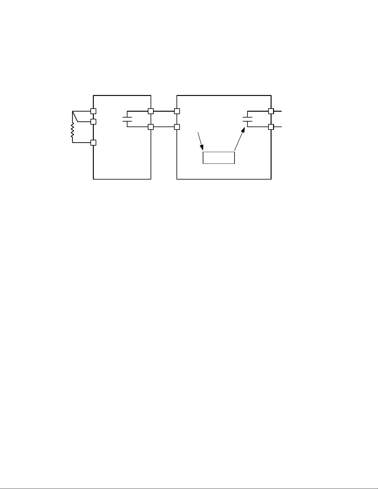
Any Temperature Controller equipped with a contact output may be connected to the M-3425A and controlled
by the relay's IPSlogic function. Figure 1 is an example of a typical Temperature Controller Monitoring
application.
Temperature
Controller
M-3425A
R1
C
IN X
Alarm/Trip
IN RTN
R2
Omron E5C2
IPSlogic
P.D. 750
or equivalent
Figure 1 Typical Temperature Controller Monitoring Application
I/O Expansion (optional)
Optional I/O Expansion provides an additional 15 form 'a' output contacts and an additional 8 control/status
inputs. Output LEDs indicate the status of the output relays.
Tests and Standards
The relay complies with the following type tests and standards:
Voltage Withstand
Dielectric Withstand
IEC 60255-5 3,500 V dc for 1 minute applied to each independent circuit to earth
3,500 V dc for 1 minute applied between each independent circuit
1,500 V dc for 1 minute applied to IRIG-B circuit to earth
1,500 V dc for 1 minute applied between IRIG-B to each independent circuit
1,500 V dc for 1 minute applied between RS-485 to each independent circuit
Impulse Voltage
IEC 60255-5 5,000 V pk, +/- polarity applied to each independent circuit to earth
5,000 V pk, +/- polarity applied between each independent circuit
1.2 by 50 μs, 500 ohms impedance, three surges at 1 every 5 seconds
Insulation Resistance
IEC 60255-5 > 40 Megaohms
–15–
Page 17

M-3425A Generator Protection Relay
Electrical Environment
Electrostatic Discharge Test
EN 60255-22-2 Class 4 (8 kV)—point contact discharge
EN 60255-22-2 Class 4 (15kV)–air discharge
Fast Transient Disturbance Test
EN 60255-22-4 Class A (4 kV, 2.5 kHz)
Surge Withstand Capability
ANSI/IEEE 2,500 V pk-pk oscillatory applied to each independent circuit to earth
C37.90.1- 2,500 V pk-pk oscillatory applied between each independent circuit
1989 5,000 V pk Fast Transient applied to each independent circuit to earth
5,000 V pk Fast Transient applied between each independent circuit
ANSI/IEEE 2,500 V pk-pk oscillatory applied to each independent circuit to earth
C37.90.1- 2,500 V pk-pk oscillatory applied between each independent circuit
2002 4,000 V pk Fast Transient burst applied to each independent circuit to earth
4,000 V pk Fast Transient burst applied between each independent circuit
■ NOTE: The signal is applied to the digital data circuits (RS-232, RS-485, IRIG-B, Ethernet communication
port and field ground coupling port) through capacitive coupling clamp.
Radiated Susceptibility
ANSI/IEEE 25-1000 Mhz @ 35 V/m
C37.90.2
Output Contacts
ANSI/IEEE Make 30 A for 0.2 seconds, off for 15 seconds for 2,000 operations, per Section 6.7.1, Tripping
C37.90.0 Output Performance Requirements
Atmospheric Environment
Temperature
IEC 60068-2-1 Cold, –20° C
IEC 60068-2-2 Dry Heat, +70° C
IEC 60068-2-3 Damp Heat, +40° C @ 93% RH
Mechanical Environment
Vibration
IEC 60255-21-1Vibration response Class 1, 0.5 g
Vibration endurance Class 1, 1.0 g
IEC 60255-21-2Shock Response Class 1, 5.0 g
Shock Withstand Class 1, 15.0 g
Bump Endurance Class 1, 10.0 g
–16–
Page 18

M-3425A Generator Protection Relay
Compliance
UL-Listed per 508 – Industrial Control Equipment
UL-Listed Component per 508A Table SA1.1 Industrial Control Panels
CSA-Certified per C22.2 No. 14-95 – Industrial Control Equipment
CE Safety Directive – EN61010-1:2001, CAT II, Pollution Degree 2 (Pending for expanded I/O option.)
Physical
Without Optional Expanded I/O
Size: 19.00" wide x 5.21" high x 10.20" deep (48.3 cm x 13.2 cm x 25.9 cm)
Mounting: The unit is a standard 19", semiflush, three-unit high, rack-mount panel design, conforming to
ANSI/EIA RS-310C and DIN 41494 Part 5 specifications. Vertical or horizontal panel-mount options are
available.
Approximate Weight: 17 lbs (7.7 kg)
Approximate Shipping Weight: 25 lbs (11.3 kg)
With Optional Expanded I/O
Size: 19.00" wide x 6.96" high x 10.2" deep (48.3 cm x 17.7 cm x 25.9 cm)
Mounting: The unit is a standard 19", semiflush, four-unit high, rack-mount panel design, conforming to ANSI/
EIA RS-310C and DIN 41494 Part 5 specifications. Vertical or horizontal panel-mount options are available.
Approximate Weight: 19 lbs (8.6 kg)
Approximate Shipping Weight: 26 lbs (11.8 kg)
Patent & Warranty
The M-3425A Generator Protection Relay is covered by U.S. Patents 5,592,393 and 5,224,011.
The M-3425A Generator Protection Relay is covered by a five year warranty from date of shipment.
Specification subject to change without notice.
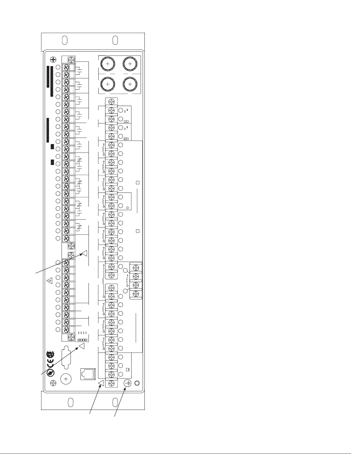
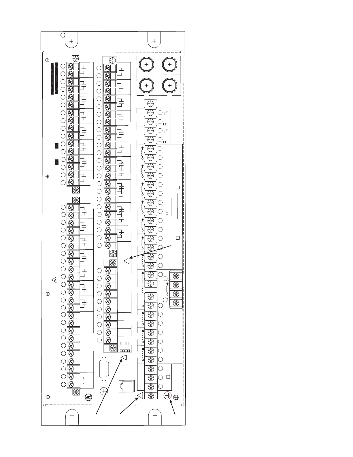
External Connections
M-3425A external connection points are illustrated in Figures 2 and 3.
–17–
Page 19
M-3425A Generator Protection Relay
3433
3130 32
29
28
27
26
25
23
22 24
50 Hz 60 Hz SERIA L NO .
MODEL: M-3425A FIRMWARE: D-0150
21
20
19
18
17
16
15
14
13
12
IN
10 11
FOR CONTACT RATINGS SEE INSTRUCTION MANUAL
9
3
WA RNING! C ONT AC T WITH TERMINAL S MAY CAUSE ELECT RIC SHOCK
8
7
6
5
4
727- 544 - 232 6
3
2
1
LARGO, FL 33773
6190 118th AVE NO.
BECKWITH ELECTRIC CO. INC.
R
NRTL/ C
LR 89464
R
83F4
2
LISTED
IND.CONT .EQ
RS2 32
COM 2
COM2
IRIG- B
IN
IN
IN
IN
IN
IN
+
+
-
4824250
ETHERNET
1
2
3
4
5
OUTPUTS
6
7
8
SELF-TEST
ALARMS
P/ S
RTN
!
1
(52b)
2
3
INPUTS
4
5
6
RS485
COM 3
AUX
125
!
PS1
F2
PS2
3AMP,250V(3AB)3AMP,250V(3AB)
F1
+
+
COUPLER
63
1-85
62
61
65-18 6
60
59
58
56
54 55 57
53
64S
52
51
50
49
48
47
46
4545
65
X
V
64
44444444
43434343
42424242
40404040 41414141
39393939
37373737 38383838
36363636
35353535
S
P1
2PS
c
b
II
a
I
N
I
C
I
B
I
A
I
N
V
A
C
C
V
V
C
B
B
V
V
BA
A
V
V
D
N
G
LDFI
E
!
5
685 2
55268
0.01A NOM
64F
F4
F3
RATED C URRENT
1A,NOM 5 A,NOM
Figure 2 External Connections (Without Optional Expanded I/O)
RATED VOLTAGE
60-140VAC,50/60Hz
88
88
88
for the information regarding setting Trip Circuit Monitoring input voltage. Connecting a voltage other than the voltage that the unit is configured
to may result in mis-operation or permanent damage to the unit.
1. See M-3425A Instruction Book Section 2.3, Setpoints and Time Settings, subsection for 64B/F Field Ground Protection.
2. Before making connections to the Trip Circuit Monitoring input, see M-3425A Instruction Book Section 5.5, Circuit Board Switches and Jumpers,
1
4
■■
■■
■ NOTES:
88
8 WARNING: ONLY DRY CONTACTS must be connected to inputs (terminals 5 through 10 with 11 common) because these contact
inputs are internally wetted. Application of external voltage on these inputs may result in damage to the units.
8 WARNING: The protective grounding terminal must be connected to an earthed ground any time external connections have been
made to the unit.
3.
4.
–18–
Page 20
M-3425A Generator Protection Relay
IN
RTN
IN IN IN IN INININ IN
8
7
9
10
11
12
14
13
INPUTS
RS2 32
COM 2
ETHERNET
COM 2
727- 544- 2326
6190 118th AVE NO.
LARGO, FL 33773
BECKWITH ELECTRIC CO. INC.
WA RNING! C ONT AC T WIT H T ERMINAL S MAY CA USE ELE CT RIC S HOC K
FOR CONTACT RATINGS SEE INSTRUCTION MANUAL
76
78
77
80
79
81
83
82
84
88
86
85
87
89
91
90
92
94
93
9695 97 9998
P/ S
36363636
35353535
44444444
40404040
3838383837373737
39393939
42424242
41414141
43434343
64
V
X
65
4545
46
47
48
49
COUPLER
D
E
IFL
IRIG- B
23
AUX
N
GD
A
V
V
AB
B
V
B
V
C
C
V
A
V
C
RS485
COM 3
+
--
6
+
IN
3
1
2
5
4
(52b)
V
N
3
IN
INPUTS
4
5
IN IN
1
2
IN IN
A
I
I
B
RTN
IN
8
7
6
10
9
22
21
12
11
20
19
3AMP,250V(3AB)3AMP,250V(3AB)
58
54
52
50
51
53
56
55
57
62
60
59
61
63
F3
F4
32
PS2
10
C
I
I
N
SELF- TEST
ALARMS
a
I
I
b
8
7
OUTPUTS
15
13
14
17
16
18
17
20
19
18
22
21
16
15
c
I
SP2
OUTPUTS
6
5
1SP
F1
3
4
2
27
24
23
25
26
14
13
29
28
31
30
12
11
PS1
F2
1
34
33
9
68
66
67
69
70
71
72
74
73
75
101
100
102
104
103
105
97
!
48
!
125
250
24
!
0.01A NOM
64S
8
8
1
6
-
25
5
856
8
1
5
26
5
56
++
--
RATED VOLTAGE
60-140VAC,50/60Hz
MODEL: M-3425A FIRMWARE: D-0150
50 Hz 6 0Hz SERIAL NO.
1A ,N O M
RATED C URRENT
5A,NOM
64F
4
3
1
2
.QE.TNOC.DNI
DETSIL
CUS
83F4
R
ay
hes and Jumpers,
he unit is configured
Figure 3 External Connections (With Optional Expaned I/O)
88
88
88
8 WARNING: ONLY DRY CONTACTS must be connected to inputs (terminals 5 through 10 with 11 common and terminals 68 through
to may result in mis-operation or permanent damage to the unit.
for the information regarding setting Trip Circuit Monitoring input voltage. Connecting a voltage other than the voltage that t
2. Before making connections to the Trip Circuit Monitoring input, see M-3425A Instruction Book Section 5.5, Circuit Board Switc
1. See M-3425A Instruction Book Section 2.3, Setpoints and Time Settings, subsection for 64B/F Field Ground Protection.
■■
■■
■ NOTES:
3.
88
made to the unit.
8 WARNING: The protective grounding terminal must be connected to an earthed ground any time external connections have been
result in damage to the units.
75 with 66 and 67 common) because these contact inputs are internally wetted. Application of external voltage on these inputs m
4.
–19–
Page 21
M-3425A Generator Protection Relay
M-3425A
Targets
(Optional)
Integral HMI
(Optional)
Metering
Waveform Capture
IRIG-B
Front RS232
Communication
Rear RS232
Communication
Rear Ethernet
Port (Optional)
Rear RS-485
Communication
Multiple Setting
Groups
Programmable I/O
Self Diagnostics
Dual Power Supply
(Optional)
Breaker
Monitoring
Trip Circuit
Monitoring
Event Log
3VO (Calculated)
59D Line Side
Voltage
(Software Select)
M-3425A Typical
Connection Diagram
87
60
FL
3VO (Calculated)
V
X
V
67N Po lari zati on
N
(Software Select)
V
X
27
59D
27
TN
32
These functions are available in
the Comprehensive Package. A
subset of these functions are also
available in a Base Package.
This function is available as a
optional protective function.
This function provides control for
the function to which it points.
50
BFPh
81R 81 27 59 24
81A
(Note 3)
59X
27
51V 50/27
67N Operating Current
(Software Select)
I
N
3I
O
87
GD
64S
59N
67N
R
50
BFN
50
BFN
50
DT
(Metering)
492132 504078
25
M
64F 64B
46
50N
51N
(Note 5)
50N
51N
M
(Metering)
Utility System
52
Unit
CT
VT (Note 1)
CT (Residual)
52
VT
Gen
VT (Note 1)
M-3921
+
-
CT
R
(Note 4)
CT (Neutral)
(Notes 2 & 5)
High-impedance Grounding with Third
Harmonic 100% Ground Fault Protection
Low-impedance Grounding with Ground Differential
and Overcurrent Stator Ground Fault Protection
■ NOTES:
1. When 25 function is enabled, 59X, 59D with VX and 67N with VX are not available, and vice versa.
2. When 67N function with IN (Residual) operating current is enabled, 87GD is not available, and vice
versa.
3. When VT source is used as a turn-to-turn fault protection device (See M-3425A Instruction Book,
Chapter 2, Application, for additional 59X applications.)
4. The current input IN can be connected either from neutral current or residual current.
5. The 50BFN, 50N, 51N, 59D, 67N (with IN or VN) and 87GD functions are unavailable when the 64S
function has been purchased. See the M-3425A Instruction Book for connection details.
Figure 4 One-Line Functional Diagram (Configured with Phase Differential)
–20–
Page 22
M-3425A Generator Protection Relay
M-3425A
Targets
(Optional)
Integral HMI
(Optional)
Metering
Waveform Capture
IRIG-B
Front RS232
Communication
Rear RS232
Communication
Rear Ethernet
Port (Optional)
Rear RS-485
Communication
Multiple Setting
Groups
Programmable I/O
M-3425A Typical
Connection Diagram
(Configured for Split-Phase Differentia l)
81R 81 59 27 24
81A
These functions are available in
the Comprehensive Package. A
subset of these functions are also
Utility System
available in a Base Package.
This function is available as a
optional protective function.
52
Unit
This function provides control for
the function to which it points.
VT (Note 1)
CT (Residual)
(Note 5)
25
M
(Metering)
(Note 2)
59X
27
64F 64B
50
DT
CT (Note 3)
M-3921
VT
VT (Note 1)
+
-
52
Gen
Self Diagnostics
Dual Po wer Supply
(Optional)
Breaker
Monitoring
Trip Circuit
Monitoring
Event Log
59D Line Side
Voltage
(Software Select)
3VO (Calculated)
V
X
V
67N Polarization
N
(Software Select)
V
3VO (Calculated)
X
27
27
59D
32
TN
64S 59N
High-impedance Grounding with Third
Harmonic 100% Ground Fault Protection
46492132 504078 60FL 51V 50/27
M
(Metering)
(Note 4)
67N
R
50N 51N
Low-impedance Grounding with
Overcurrent Stator Ground Fault Protection
CT
CT
R
■ NOTES:
1. When 25 function is enabled, 59X, 59D with VX and 67N with VX are not available, and vice versa.
2. When used as a turn-turn fault protection device.
3. CTs are connected for split-phase differential current.
4. 67N operating current can only be selected to IN (Residual) for this configuration.
5. The current input (IN) can be connected either from neutral current or residual current.
6. The 50BFN, 50N, 51N, 59D, 67N (with IN or VN) and 87GD functions are unavailable when the 64S
function has been purchased. See the M-3425A Instruction Book for connection details.
CT (Neutral)
(Note 5)
Figure 5 One-Line Functional Diagram (configured for split-phase diffential)
–21–
Page 23
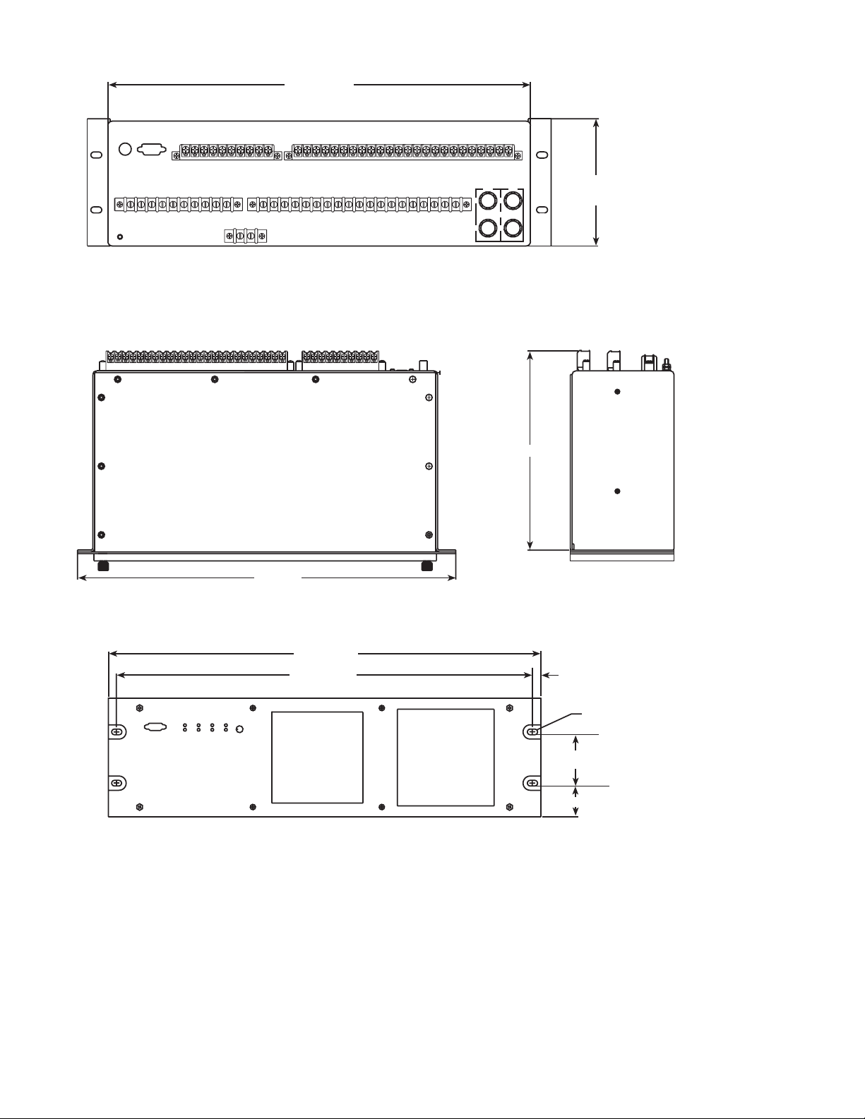
M-3425A Generator Protection Relay
Rear View
17.48 [44.4]
ACTUAL
5.21 [13.23]
ACTUAL
10.20 [25.91]
19.00
[48.26]
19.00 [48.26]
18.34 [46.58]
Standard 19" Horizontal Mount Chassis
n NOTE: Dimensions in brackets are in centimeters.
Figure 6 Horizontal Mounting Dimensions (Without Expanded I/O)
■ NOTE: Panels for vertical mounting are available (See Figure 8).
0.33
[0.84]
0.40 [1.02] x 0.27 [0.68] SLOT (4x)
2.35 [5.96]
1.35 [3.42]
–22–
Page 24
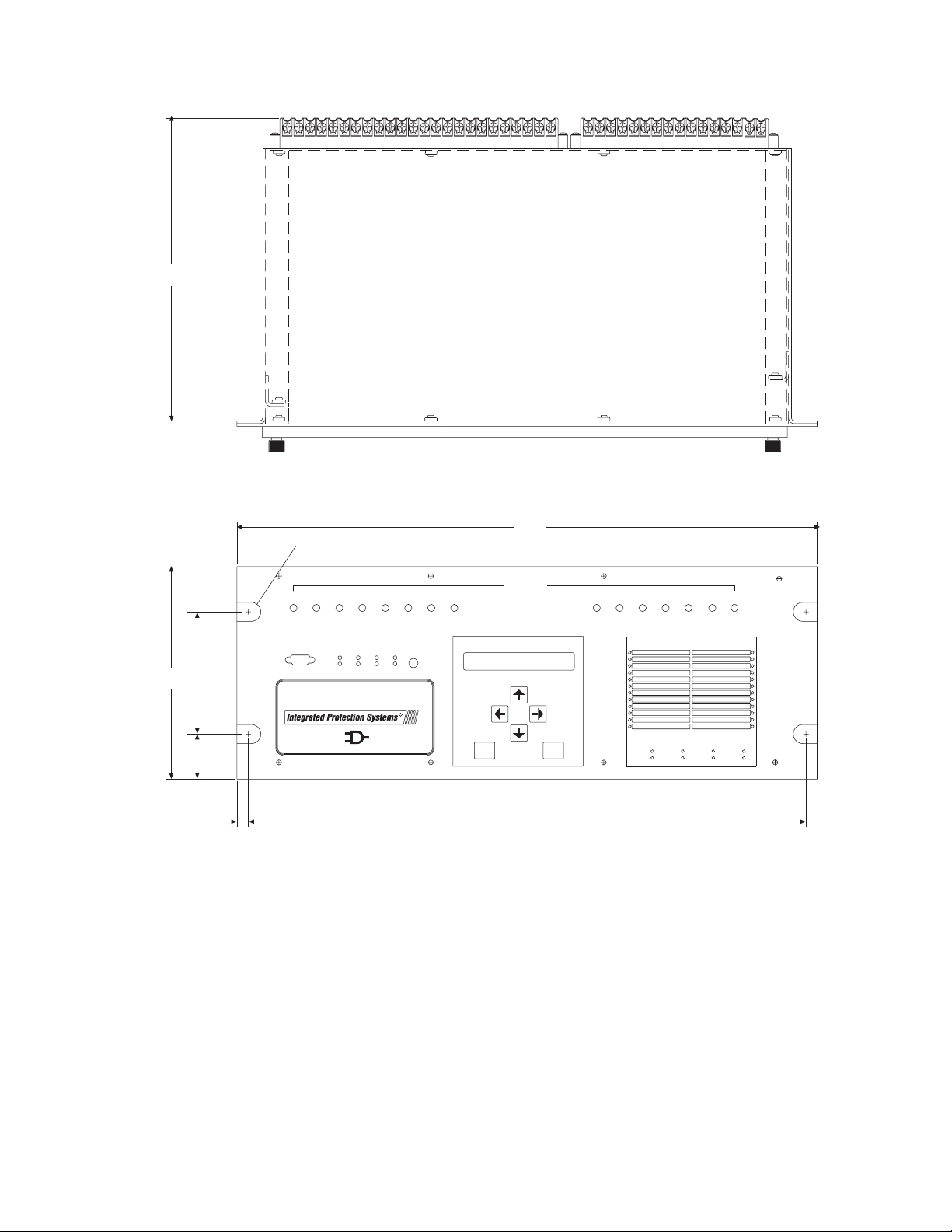
10.20
[25.9]
M-3425A Generator Protection Relay
6.96
[17.68]
4.00
[10.16]
1.48
3.76
0.33
[0.84]
19.00
.25 X .45 SLOT [.64 X 1.14]
4 PLACES
11910 121314
RELAY
COM 1
BRKR
OK
CLOSED
TIME
OSC.
SYNC
TRIG
TARGET
15
16
TARGET
PS 1
RESET
PS 2
[48.26]
OUTPUTS
17 1918 20 21 22 23
TARGET
M-3425A
GENERATOR PROTECTION
T
B
KCEWI
H
ECELT
R
IC
Made in U.S.A.
R
OINC..C
EXIT
18.34
[46.58]
ENTER
OUTPUTS
OUT 1
OUT 3
OUT 2
OUT 5
OUT 4
OUT 6
Figure 7 Horizontal Mounting Dimensions (With Expanded I/O)
OUT 7
OUT 8
–23–
Page 25
M-3425A Generator Protection Relay
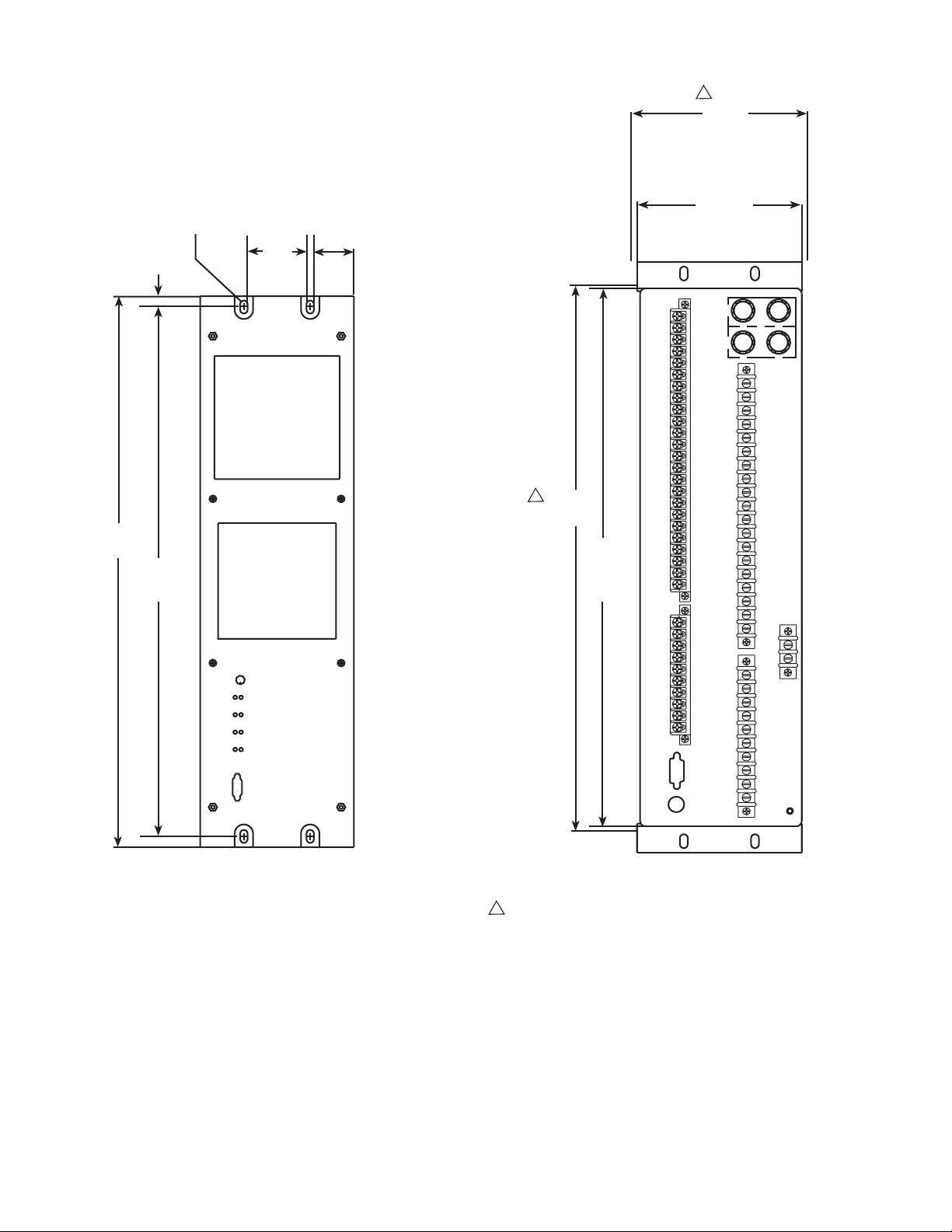
5.65
[13.41]
19.00
[48.26]
0.40 [1.02] x
0.27 [0.68]
SLOT (4x)
0.33
[0.84]
18.34
[46.58]
2.25
[5.72]
5.59
[14.20]
ACTUAL
1.71
[4.34]
17.5
[44.45]
17.31
[43.97]
Actual
n NOTE: Dimensions in brackets are
in centimeters.
RECOMMENDED CUTOUT WHEN
Rear View
RELAY IS A PANEL MOUNT
Optional Vertical Mount Chassis
■ NOTES:
1. When mounted vertically, the target module will be located at the top and all front-panel text will be
horizontally aligned. Consult Beckwith Electric Co. for details.
2. Expanded I/O not avilable on vertical mount chassis model.
Figure 8 Vertical Mounting Dimensions (Without Expanded I/O)
–24–
Page 26
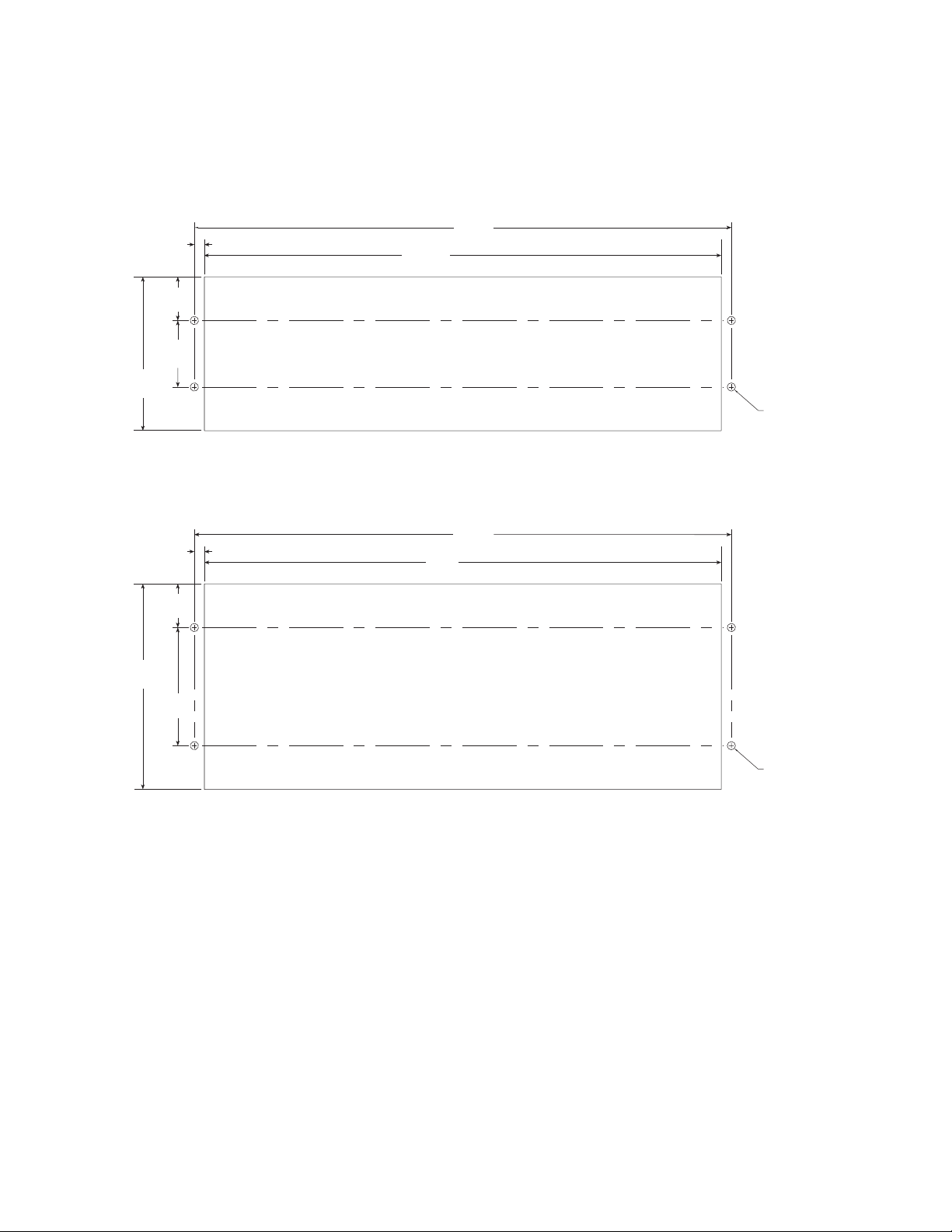
5.28
[13.40]
.34
[.86]
1.48
[3.76]
2.25
[5.72]
18.34
[46.17]
17.50
[44.45]
RECOMMENDED CUTOUT
STANDARD 3 UNIT PANEL M-3425A
M-3425A Generator Protection Relay
\U+2205.28 (4X)
7.03
[17.86]
.34
[.86]
1.48
[3.76]
4.00
[10.16]
18.34
[46.17]
17.50
[44.45]
RECOMMENDED CUTOUT
4 UNIT PANEL M-3425A (EXTENDED I/O)
TOLERANCE: .XX±.015
Figure 9 M-3425A Panel Mount Cutout Dimensions
\U+2205.28 (4X)
–25–
Page 27
M-3425A Generator Protection Relay
M-3921 Field Ground Coupler
PROTECTION RELAY
M-3425A
PROCESSOR
Excitation
System
Field Ground
Detection
Squarewave
Generator
Signal
Measurement
and Processing
COUPLING
NETWORK
(M-3921)
Gen.
Rotor
Ground/Machine Frame
Brushes
Ground
Shaft
Brush
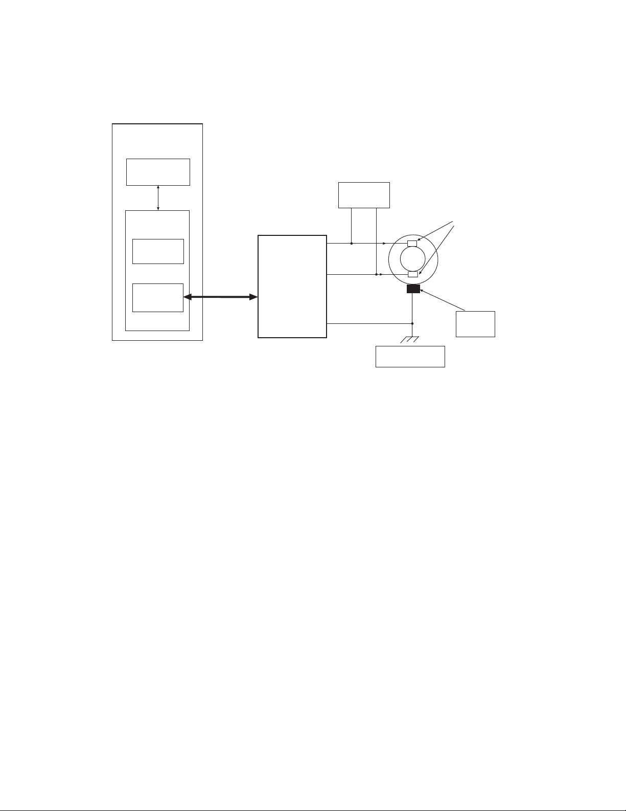
Figure 10 Field Ground Protection Block Diagram
NOTES:
1. The above circuit measures insulation resistance (Rf) between rotor field winding and ground (64F).
2. Relay injects 15 V squarewave (V
3. The injection frequency can be set (0.1 to 1.0 Hz) based on the rotor capacitance, in order to
improve accuracy.
4. The signal rise time is analyzed to determine if shaft brushes are lifting or open (64B).
5. May also be applied on generators with brushless excitation with a grounding brush and pilot
ground fault detection brush.
) and measures return signal (Vf) to calculate Rf.
out
Function Specification
Field/Exciter Supply Voltage Rating (Terminal (3) to (2)):
• 60 to 1200 V dc, continuous
• 1500 V dc, 1 minute
Operating Temperature: –20° to +70°, Centigrade
Patent & Warranty
The M-3921 Field Ground Coupler is covered by a five-year warranty from date of shipment.
Tests and Standards
M-3921 Field Ground Coupler complies with the following tests and standards:
–26–
Page 28

M-3425A Generator Protection Relay
Voltage Withstand
Isolation
4 kV ac for 1 minute, all terminals to case
Impulse Voltage
IEC 60255–5, 5,000 V pk, 1.2 by 50 μs, 0.5 J, 3 positive and 3 negative impulses at 5 second
intervals per minute
Electrical Interference
Electrostatic Discharge Test
IEC 61000-4-2 Class 4 (8 kV)—point contact discharge
Fast Transient Disturbance Tests
IEC 61000-4-4 Class 4 (4 kV, 2.5 kHz)
Surge Withstand Capability
ANSI/IEEE 2,500 V pk-pk oscillatory applied to each independent circuit to earth
C37.90.1- 2,500 V pk-pk applied between each independent circuit
1989 5,000 V pk Fast Transient applied to each independent circuit to earth
5,000 V pk Fast Transient applied between each independent circuit
■ NOTE: See also M-3425A Surge Withstand Capability test standards, ANSI/IEEE C37.90.2-2002.
Radiated Susceptibility
ANSI/IEEE 25-1000 Mhz @ 20 V/m
C37.90.2
Atmospheric Environment
IEC 60068–2–1 Cold, –20° C
IEC 60068–2–2 Dry Heat, +70° C
IEC 60068–2–3 Damp Heat, +40° C @ 93% RH
Enclosure Protection
NEMA 1, IEC IPC-65
–27–
Page 29
7.87 [19.99]
2.96 REF [7.52]
3.54 [9.0]
4.72 [11.99]
.18 DIA [0.46] 4 X
3.54 [9.0]
M-3921
Field Ground
Coupler
BECKWITH
CO. I NC.
ELECTRIC
Made in U.S.A.
9.06 [23.01]
.18 DIA [0.46] 4 HOLES
7.40
[18.79]
MOUNTING PATTERN
WITHOUT TABS
nNOTE: Dimensions in brackets are in centimeters.
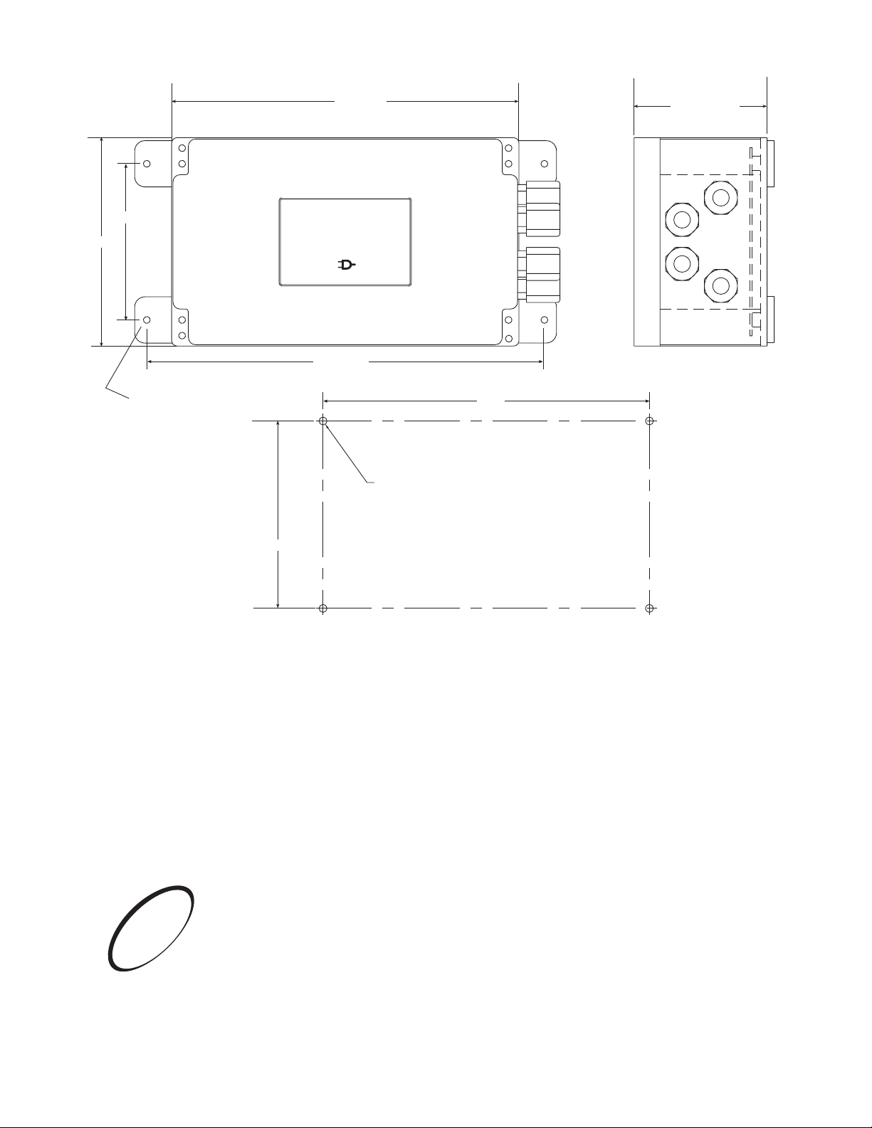
Figure 11 M-3921 Field Ground Coupler Mounting Dimensions
0
0
0
2
:
d
1
e
r
0
e
0
t
s
9
i
g
e
O
R
S
I
6190 - 118th Avenue North • Largo, Florida 33773-3724 U.S.A.
© 2001 Beckwith Electric Co.
Printed in U.S.A. (#01-67) (04.25.03)
BECKWITH ELECTRIC CO., INC.
PHONE (727) 544-2326 • FAX (727) 546-0121
E-MAIL [email protected]
WEB PAGE www.beckwithelectric.com
800-3425A-SP-01MC5 1/06
Page 30
WARNING
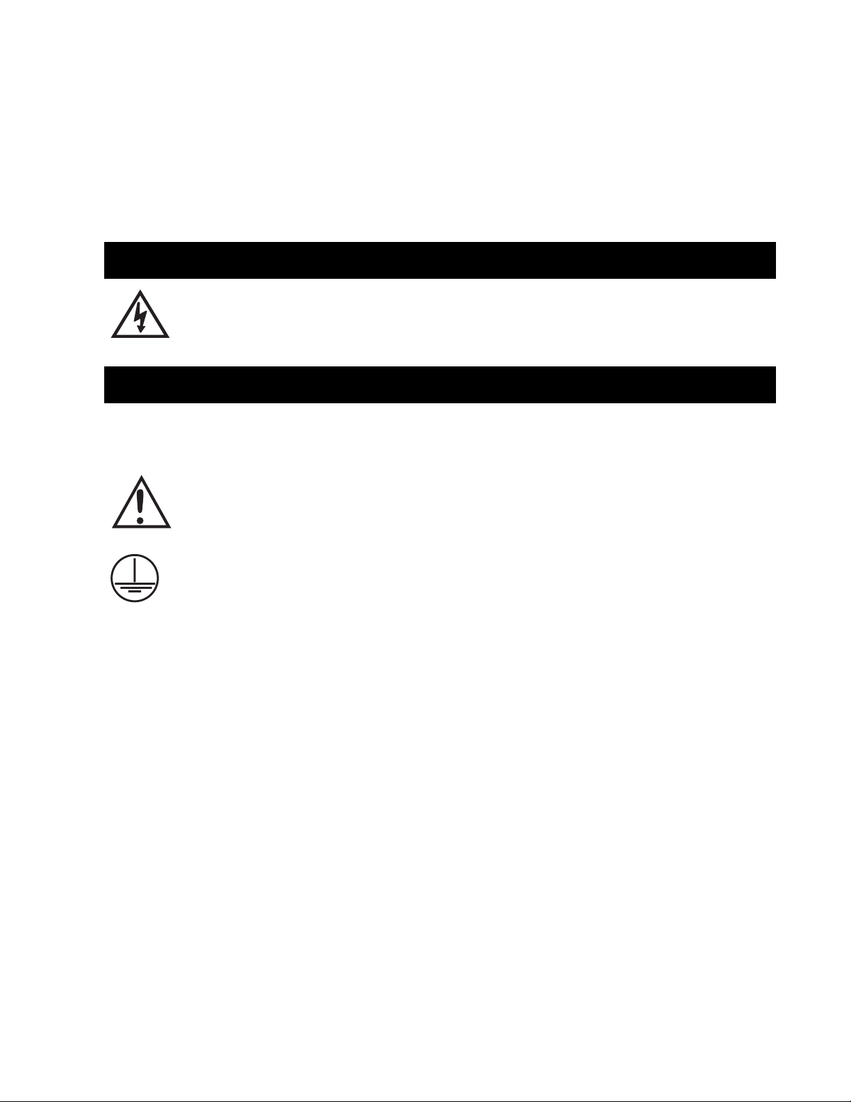
DANGEROUS VOLTAGES, capable of causing death or serious
injury, are present on the external terminals and inside the equipment. Use extreme caution and follow all safety rules when handling, testing or adjusting the equipment. However, these internal
voltage levels are no greater than the voltages applied to the external terminals.
DANGER! HIGH VOLTAGE
– This sign warns that the area is connected to a dangerous high voltage, and you
must never touch it.
PERSONNEL SAFETY PRECAUTIONS
The following general rules and other specific warnings throughout the manual must be followed during application,
test or repair of this equipment. Failure to do so will violate standards for safety in the design, manufacture, and intended
use of the product. Qualified personnel should be the only ones who operate and maintain this equipment. Beckwith
Electric Co., Inc. assumes no liability for the customer’s failure to comply with these requirements.
– This sign means that you should refer to the corresponding section of the operation
manual for important information before proceeding.
Always Ground the Equipment
To avoid possible shock hazard, the chassis must be connected to an electrical ground. When servicing
equipment in a test area, the Protective Earth Terminal must be attached to a separate ground securely
by use of a tool, since it is not grounded by external connectors.
Do NOT operate in an explosive environment
Do not operate this equipment in the presence of flammable or explosive gases or fumes. To do so would
risk a possible fire or explosion.
Keep away from live circuits
Operating personnel must not remove the cover or expose the printed circuit board while power is applied. In no case may components be replaced with power applied. In some instances, dangerous voltages may exist even when power is disconnected. To avoid electrical shock, always disconnect power and
discharge circuits before working on the unit.
Exercise care during installation, operation, & maintenance procedures
The equipment described in this manual contains voltages high enough to cause serious injury or death.
Only qualified personnel should install, operate, test, and maintain this equipment. Be sure that all personnel safety procedures are carefully followed. Exercise due care when operating or servicing alone.
Do not modify equipment
Do not perform any unauthorized modifications on this instrument. Return of the unit to a Beckwith
Electric repair facility is preferred. If authorized modifications are to be attempted, be sure to follow
replacement procedures carefully to assure that safety features are maintained.
Page 31

PRODUCT CAUTIONS
Before attempting any test, calibration, or maintenance procedure, personnel must be completely familiar
with the particular circuitry of this unit, and have an adequate understanding of field effect devices. If a
component is found to be defective, always follow replacement procedures carefully to that assure safety
features are maintained. Always replace components with those of equal or better quality as shown in the
Parts List of the Instruction Book.
Avoid static charge
This unit contains MOS circuitry, which can be damaged by improper test or rework procedures. Care
should be taken to avoid static charge on work surfaces and service personnel.
Use caution when measuring resistances
Any attempt to measure resistances between points on the printed circuit board, unless otherwise noted
in the Instruction Book, is likely to cause damage to the unit.
Page 32

NOTE
The following features, described in this Instruction Book, are only available for firmware version
D-0150-V01.00.33 and later:
59N 20 Hz Injection Mode (Page 2-58)
IEEE curves for 51N, 51V, and 67N functions (Appendix D)
Sequence of Events Recorder (Page 4-18)
Dropout/Reset Time Delay added to IPSlogic (Page 2-91)
Response Time Delay for Communications (Page 4-3)
25 Function (does not produce a target) (Page 2-21)
Page 33

This Page Left Intentionally Blank
Page 34

Table of Contents
Table of Contents
M-3425A Generator Protection
Instruction Book
Chapters - Part 1 of 2 Page
Chapter 1 Introduction
1.1 Instruction Book Contents ................................................................. 1–1
1.2 M-3425A Generator Protection Relay ................................................ 1–2
1.3 Accessories ........................................................................................ 1–4
Chapter 2 Application
2.1 Configuration ...................................................................................... 2–1
Profiles ................................................................................................ 2–2
Functions ............................................................................................ 2–2
Special Considerations ........................................................................ 2–2
Relay System Setup .......................................................................... 2–3
2.2 System Diagrams ............................................................................... 2–7
2.3 Setpoints and Time Settings ........................................................... 2–13
21 Phase Distance ........................................................................... 2–14
24 Overexcitation Volts/Hz .............................................................. 2–18
25 Sync Check ................................................................................. 2–21
27 Phase Undervoltage .................................................................... 2–25
27TN Third Harmonic Undervoltage, Neutral .................................. 2–26
32 Directional Power ........................................................................ 2–30
40 Loss of Field ............................................................................... 2–35
46 Negative Sequence Overcurrent ................................................. 2–39
49 Stator Overload Protection ......................................................... 2–41
50/50N Instantaneous Overcurrent,Phase & Neutral Circuits ........ 2–44
50BF Generator Breaker Failure/HV Breaker Flashover................. 2–46
50DT Definite Time Overcurrent (for split-phase differential) ........ 2–49
50/27 Inadvertant Energizing ........................................................... 2–50
51N Inverse Time Neutral Overcurrent............................................ 2–52
51V Inverse Time Phase Overcurrent with
Voltage Control/Restraint ................................................................. 2–53
59 Phase Overvoltage...................................................................... 2–55
59D Third Harmonic Voltage Differential ......................................... 2–56
59N Overvoltage, Neutral Circuit or Zero Sequence ...................... 2–58
59X Multipurpose Overvoltage (Turn-to-Turn Stator Fault
or Bus Ground Protection) ............................................................... 2–59
60FL VT Fuse Loss ......................................................................... 2–61
64B/F Field Ground Protection ........................................................ 2–64
64F Field Ground Protection ............................................................ 2–64
64B Brush Lift-Off Detection ........................................................... 2–66
64S 100% Stator Ground Protection by Low Frequency
Signal Injection ................................................................................. 2–67
i
Page 35

M-3425A Instruction Book
Chapters - Part 1 of 2 (cont'd) Page
Chapter 2 Application (cont'd)
67N Residual Directional Overcurrent ............................................. 2–70
78 Out of Step .................................................................................. 2–73
81 Frequency .................................................................................... 2–76
81A Frequency Accumulators ............................................................ 2–78
81R Rate of Change of Frequency ......................................................2–80
87 Phase Differential ..........................................................................2–81
87GD Ground (Zero Sequence) Differential ......................................... 2–83
Breaker Monitoring.............................................................................. 2–84
Trip Circuit Monitoring .........................................................................2–85
IPSlogic ..............................................................................................2–87
Chapter 3 Operation
3.1 Front Panel Controls ............................................................................ 3–1
Alphanumeric Display .......................................................................... 3–1
Screen Blanking .................................................................................. 3–1
Arrow Pushbuttons .............................................................................. 3–1
Exit Pushbutton ................................................................................... 3–1
Enter Pushbutton ................................................................................. 3–1
Target & Status Indicators and Controls .............................................. 3–1
Power Supply #1 (#2) LED ................................................................... 3–2
Relay OK LED ..................................................................................... 3–2
Oscillograph Recorded LED ................................................................. 3–2
Breaker Closed LED ............................................................................ 3–2
Target Indicators and Target Reset ..................................................... 3–2
Time Sync LED ................................................................................... 3–2
Diagnostic LED .................................................................................... 3–2
Accessing Screens ............................................................................. 3–2
Default Message Screens .................................................................. 3–2
3.2 Initial Setup Procedure/Settings ........................................................ 3–5
3.3 Setup Unit Data ................................................................................... 3–5
Setup Unit Data Entry .......................................................................... 3–5
Setup Unit Features That Do Not Require Data Entry .......................... 3–6
3.4 Setup System Data ............................................................................. 3–6
Configure Relay Data ........................................................................... 3–7
Setpoints and Time Settings ............................................................... 3–7
Oscillograph Recorder Data ................................................................. 3–8
Communications Settings .................................................................... 3–8
3.5 Status/Metering ................................................................................... 3–9
3.6 Target History .....................................................................................3–10
ii
Page 36

Table of Contents
Chapters - Part 1 of 2 (cont'd) Page
Chapter 4 Remote Operation
4.1 Remote Operation............................................................................... 4–1
Serial Ports (RS-232) ......................................................................... 4–1
Serial Port (RS-485) ............................................................................. 4–1
Optional Ethernet Port ......................................................................... 4–1
Direct Connection ................................................................................ 4–2
Setting up the M-3425A Generator Protection
Relay for Communication ..................................................................... 4–3
Serial Communication Settings............................................................ 4–3
Ethernet Communication Settings ....................................................... 4–3
DHCP Protocol .................................................................................... 4–3
Ethernet Protocols ............................................................................... 4–3
Ethernet Port Setup ............................................................................. 4–4
HMI Ethernet Port Setup ..................................................................... 4–4
Manual Configuration of Ethernet Board .............................................. 4–5
IPSutil™ Ethernet Port Setup with DHCP ............................................ 4–5
IPSutil Ethernet Port Setup without DHCP .......................................... 4–5
Installing the Modems ........................................................................ 4–7
4.2 Installation and Setup (IPScom®) ........................................................ 4–8
4.3 Operation ............................................................................................ 4–8
Activating Communications................................................................ 4–8
Overview ............................................................................................. 4–9
File Menu ............................................................................................ 4–9
Comm Menu ....................................................................................... 4–9
Relay Menu ....................................................................................... 4–10
Window Menu/Help Menu ................................................................. 4–21
4.4 Checkout Status/Metering ................................................................ 4–22
4.5 Cautions ............................................................................................ 4–27
4.6 Keyboard Shortcuts .......................................................................... 4–28
4.7 IPSutil Communications Software ...................................................... 4–29
M-3890 IPSutil ...................................................................................4–29
Installation and Setup .........................................................................4–29
Installation .......................................................................................... 4–30
System Setup ....................................................................................4–30
Overview............................................................................................. 4–30
Comm Menu .......................................................................................4–30
Relay Comm Command ......................................................................4–30
Ethernet Command .............................................................................4–30
Clock Command ................................................................................. 4–30
Security Menu .................................................................................... 4–31
Miscellaneous Menu ...........................................................................4–31
Help Menu .......................................................................................... 4–32
iii
Page 37

M-3425A Instruction Book
Figures - Part 1 of 2 Page
Chapter 1
1-1 M-3925A Target Module ..................................................................... 1–3
1-2 M-3931 Human-Machine Interface (HMI) Module............................. 1–4
Chapter 2
2-1 Setup System Dialog Box ................................................................. 2–5
2-2 Selection Screen for Expanded Input ............................................... 2–6
2-3 Pulse Relay Expanded Output Screen.............................................. 2–6
2-4 Latch Relay Expanded Output Screen .............................................. 2–6
2-5 One-Line Functional Diagram............................................................. 2–7
2-6 Alternative One-Line Functional Diagram
(configured for split-phase differential) .............................................. 2–8
2-7 Three-Line Connection Diagram ......................................................... 2–9
2-8 Function 25 Sync Check Three-Line Connection Diagram............. 2–10
2-9 Function 59X Turn-to-Turn Fault Protection Three-Line
Connection Diagram ......................................................................... 2–11
2-10 Function 67N, 59D, 59X (Bus Ground) Three-Line
Connection Diagram ......................................................................... 2–12
2-11 Selection Screen for Expanded I/O Initiate .................................... 2–13
2-12 Phase Distance (21) Coverage ........................................................ 2–15
2-13 Phase Distance (21) Function Applied for System Backup ........... 2–16
2-14 Phase Distance (21) Setpoint Ranges ............................................ 2–17
2-15 Example of Capability and Protection Curves (24) ......................... 2–19
2-16 Volts-per-Hertz (24) Setpoint Ranges .............................................. 2–20
2-17 Sync Check Logic Diagrams ........................................................... 2–23
2-18 Sync Check (25) Setpoint Ranges .................................................. 2–24
2-19 Phase Undervoltage (27) Setpoint Ranges ..................................... 2–25
2-20 Third-Harmonic Undervoltage (27TN) Protection Characteristics ... 2–27
2-21 27TN Blocking Regions .................................................................... 2–28
2-22 Third Harmonic Undervoltage, Neutral Circuit (27TN)
Setpoint Ranges ............................................................................... 2–29
2-23 Tripping on Reverse Power Flow
(Over Power with Negative Pickup) ................................................. 2–31
2-24 Tripping on Low Foward Power
(Under Power with Positive Pickup) ................................................ 2–32
2-25 Tripping on Overpower (Over Power with Positive Pickup) ........... 2–32
iv
Page 38

Table of Contents
Figures - Part 1 of 2 Page
Chapter 2 (cont'd)
2-26 Tripping on Over Reactive Power with Element #3
(Over Power, Positive Pickup and Directional Power Sensing
Set to Reactive) ............................................................................... 2–33
2-27 Directional Power, 3-Phase (32) Setpoint Ranges .......................... 2–34
2-28 Loss of Field (40) Protective Approach 1 ....................................... 2–37
2-29 Loss of Field (40) Protective Approach 2 ....................................... 2–37
2-30 Loss of Field (40) Setpoint Ranges ................................................ 2–38
2-31 Negative Sequence Overcurrent Inverse Time Curves .................. 2–40
2-32 Negative Sequence Overcurrent (46) Setpoint Ranges .................. 2–40
2-33 Time Constant, Function 49 ............................................................ 2–41
2-34 49 Function Overload Curves .......................................................... 2–42
2-35 Stator Thermal Protection (49) Setpoint Ranges ............................ 2–43
2-36 Instantaneous Overcurrent (50) Setpoint Ranges ........................... 2–44
2-37 Instantaneous Neutral Overcurrent (50N) Setpoint Ranges ........... 2–45
2-38 Breaker Failure Logic Diagram ........................................................ 2–47
2-39 Breaker Failure (50BF) Setpoint Ranges ........................................ 2–48
2-40 Definite Time Overcurrent (50DT) Setpoint Ranges ....................... 2–49
2-41 Inadvertent Energizing Function Logic Diagram ............................. 2–51
2-42 Inadvertent Energizing (50/27) Setpoint Ranges ............................ 2–51
2-43 Inverse Time Neutral Overcurrent (51N) Setpoint Ranges ............. 2–52
2-44 Voltage Restraint (51VR) Characteristic ......................................... 2–54
2-45 Inverse Time Overcurrent with Voltage Control/Voltage
Restraint (51VC/VR) Setpoint Ranges ............................................ 2–54
2-46 Phase Overvoltage (59) Setpoint Ranges ....................................... 2–55
2-47 Third Harmonic Overvoltage Scheme for Generator
Ground-Fault Protection ................................................................... 2–57
2-48 Third Harmonic Voltage Differential (59D) Setpoint Ranges .......... 2–57
2-49 Overvoltage, Neutral Circuit or Zero Sequence (59N)
Setpoint Ranges ............................................................................... 2–58
2-50 Turn-to-Turn Stator Winding Fault Protection ................................. 2–59
2-51 Multipurpose Overvoltage (59X) Setpoint Ranges .......................... 2–60
2-52 Fuse Loss (60FL) Function Logic .................................................... 2–62
2-53 Fuse Loss (60FL) Setpoint Ranges ................................................. 2–63
2-54 M-3921 Field Ground Coupler .......................................................... 2–64
2-55 Field Ground Protection (64B/F) Setpoint Ranges ......................... 2–65
v
Page 39

M-3425A Instruction Book
Figures - Part 1 of 2 (cont'd) Page
Chapter 2 (cont'd)
2-56 64S Function Component Connection Diagram .............................. 2–68
2-57 64S Function Time Delay Pickup Current Correlation .................... 2–68
2-58 100% Stator Ground Protection (64S) Setpoint Ranges ................ 2–69
2-59 Residual Directional Overcurrent (67N) Trip Characteristics .......... 2–70
2-60 Residual Directional Overcurrent (67N) Setpoint Ranges ............... 2–72
2-61 Out-of-Step Relay Characteristics ................................................... 2–74
2-62 Out-of-Step Protection Settings ....................................................... 2–74
2-63 Out-of-Step (78) Setpoint Ranges ................................................... 2–75
2-64 Example of Frequency (81) Trip Characteristics ............................ 2–77
2-65 Frequency (81) Setpoint Ranges ..................................................... 2–77
2-66 Frequency Accumulator (81A) Example Bands .............................. 2–79
2-67 Frequency Accumulator (81A) Setpoint Ranges ............................. 2–79
Chapter 3
2-68 Rate of Change of Frequency (81R) Setpoint Ranges ................... 2–80
2-69 Differential Relay (87) Operating Characteristics............................ 2–81
2-70 Phase Differential (87) Setpoint Ranges ......................................... 2–81
2-71 Ground Differential (87GD) Setpoint Ranges .................................. 2–83
2-72 Breaker Monitor (BM) Setpoint Ranges........................................... 2–84
2-73 Trip Circuit Monitoring Input ............................................................ 2–85
2-74 Trip Circuit Monitor (TC) Setpoint Ranges ...................................... 2–86
2-75 IPSlogic™ Function Setup ............................................................... 2–88
2-76 IPSlogic Function Programming ......................................................... 2–89
2-77 Selection Screen for Initiating Function Timeout ................................ 2–90
2-78 Selection Screen for Initiating Function Pickup .................................. 2–90
2-79 Dropout Delay Timer Logic Diagram ................................................... 2–91
2-80 Reset Delay Timer Logic Diagram ...................................................... 2–91
3-1 M-3425A Front Panel ......................................................................... 3–3
3-2 Screen Message Menu Flow ............................................................. 3–3
3-3 Main Menu Flow ................................................................................. 3–4
vi
Page 40

Table of Contents
Figures - Part 1 of 2 (cont'd) Page
Chapter 4
4-1 Multiple System Addressing Using
Communications Line Splitter ............................................................ 4–2
4-2 IPScom® Menu Selections ................................................................ 4–6
4-3 IPScom Program Icon ........................................................................ 4–8
4-4 New Device Profile Dialog Box.......................................................... 4–9
4-5 Communication Dialog Box.............................................................. 4–10
4-6 Setup System Dialog Box ............................................................... 4–11
4-7 Expanded Input Active State........................................................... 4–12
4-8 Pulse Relay Expanded Output Screen............................................ 4–12
4-9 Latch Relay Expanded Output Screen ............................................ 4–12
4-10 Relay Setpoints Dialog Box ............................................................. 4–13
4-11 Typical Setpoint Dialog Box ............................................................ 4–13
4-12 Expanded I/O Initiate ....................................................................... 4–13
4-13 All Setpoints Table Dialog Box (Partial) ......................................... 4–14
4-14 Configure Dialog Box (Partial) ......................................................... 4–15
4-15 Configure Dialog Box Partial
(shown with Expanded Input/Outputs) ............................................. 4–16
4-16 Unit Date/Time Dialog Box .............................................................. 4–17
4-17 Target Dialog Box............................................................................. 4–18
4-18 Trigger Events Screen with Expanded I/O ..................................... 4–19
4-19 Event Log Viewer ............................................................................. 4–19
4-20 Event Download Screen ................................................................... 4–20
4-21 Setup Oscillograph Recorder ........................................................... 4–20
4-22 Retrieve Oscillograph Record Dialog ............................................... 4–20
4-23 Profile Switching Method Dialog ...................................................... 4–20
4-24 Select Active Profile ........................................................................ 4–21
4-25 Copy Active Profile .......................................................................... 4–21
4-26 About IPScom® Dialog Box ............................................................. 4–21
4-27 Primary Status Dialog Box .............................................................. 4–22
4-28 Secondary Status Dialog Box.......................................................... 4–22
4-29 Accumulator Status Screen ............................................................. 4–23
4–30 Phase Distance Dialog Box ............................................................. 4–23
4-31 Loss of Field Dialog Box ................................................................. 4–24
4-32 Out of Step Dialog Box ................................................................... 4–24
vii
Page 41

M-3425A Instruction Book
Figures - Part 1 of 2 (cont'd) Page
Chapter 4 (cont.)
4-33 Phasor Dialog Box ........................................................................... 4–25
4-34 Sync Scope Screen ......................................................................... 4–25
4-35 Function Status Screen ................................................................... 4–26
4-36 IPSutil™ Main Menu Flow ............................................................... 4–29
4-37 Warning Message ............................................................................. 4–30
4-38 IPSutility Reset Relay Message ..................................................... 4–30
4-39 Monitor Status Screen ..................................................................... 4–31
4-40 Calibration Dialog Box ...................................................................... 4–31
4-41 Communication Dialog Box .............................................................. 4–32
4-42 Relay Comm Port Settings .............................................................. 4–32
4-43 Ethernet Settings .............................................................................. 4–32
4-44 Unit Date/Time Dialog Box .............................................................. 4–32
4-45 Change Communication Access Code Dialog Box ......................... 4–33
4-46 Change User Access Code Dialog Box .......................................... 4–33
4-47 Setup Dialog Box ................................................................................ 4–33
Tables - Part 1 of 2 Page
Chapter 1
1-1 M-3425A Device Functions................................................................ 1–2
Chapter 2
2-1 Input Activated Profile ....................................................................... 2–3
2-2 Impedance Calculation ..................................................................... 2–17
2-3 Voltage Control Time Settings......................................................... 2–36
2-4 Delta/Wye Transformer Voltage-Current Pairs ................................ 2–54
2-5 Typical Frequency Settings ............................................................. 2–65
2-6 Typical Brush Lift-Off Settings ...........................................................2–66
Chapter 3
3-1 Recorder Partitions .............................................................................. 3–8
viii
Chapter 4
4-1 Dead-Sync Time .................................................................................. 4–3
4-2 Microsoft Windows Keyboard Shortcuts .............................................4–28
Page 42

Table of Contents
Chapters - Part 2 of 2 Page
Chapter 5 Installation
5.1 General Information ............................................................................ 5–1
5.2 Mechanical/Physical Dimensions ...................................................... 5–1
5.3 External Connections ......................................................................... 5–9
5.4 Commissioning Checkout ................................................................ 5–15
5.5 Circuit Board Switches and Jumpers .............................................. 5–20
Chapter 6 Testing
6.1 Equipment/Test Setup ........................................................................ 6–2
6.2 Functional Test Procedures ............................................................... 6–6
Power On Self Tests ......................................................................... 6–7
21 Phase Distance .............................................................................. 6–8
24 Volts per Hertz, Definite Time......................................................... 6–9
24 Volts per Hertz, Inverse Time ........................................................6–10
25D Dead Check ................................................................................6–12
25S Sync Check ................................................................................6–14
27 Phase Undervoltage ....................................................................... 6–16
27TN Third-Harmonic Undervoltage, Neutral .......................................6–17
32 Directional Power, 3-Phase............................................................ 6–21
40 Loss of Field ..................................................................................6–24
46 Negative Sequence Overcurrent Definite Time .............................. 6–26
46 Negative Sequence Overcurrent Inverse Time ..............................6–27
49 Stator Overload Protection ......................................................... 6–28
50 Instantaneous Phase Overcurrent .............................................. 6–30
50BF/50BF-N Breaker Failure .......................................................... 6–31
50/27 Inadvertant Energizing ........................................................... 6–33
50DT Definite Time Overcurrent for Split-Phase Differential ......... 6–34
50N Instantaneous Neutral Overcurrent ......................................... 6–35
51N Inverse Time Neutral Overcurrent .......................................... 6–36
51V Inverse Time Phase Overcurrent with
Voltage Control/Restraint ................................................................. 6–37
59 RMS Overvoltage, 3-Phase ........................................................ 6–39
59D Third-Harmonic Voltage Differential ......................................... 6–40
59N Overvoltage, Neutral Circuit or Zero Sequence ...................... 6–41
59X Multipurpose Overvoltage ............................................................ 6–42
60FL VT Fuse Loss Detection ............................................................6–43
64F Field Ground Protection ...............................................................6–44
64B Brush Lift Off Detection...............................................................6–46
64S 100% Stator Ground Protection by Injection ...............................6–47
67N Residual Directional Overcurrent, Definite Time .......................... 6–49
67N Residual Directional Overcurrent, Inverse Time ..........................6–51
78 Out of Step ....................................................................................6–53
81 Frequency ...................................................................................... 6–55
81A Frequency Accumulator .............................................................. 6–56
81R Rate of Change of Frequency .................................................. 6–57
ix
Page 43

M-3425A Instruction Book
Chapters - Part 2 of 2 (cont'd) Page
Chapter 6 Testing (cont'd)
87 Phase Differential ..........................................................................6–59
87GD Ground Differential ................................................................... 6–61
BM Breaker Monitoring .......................................................................6–63
Trip Circuit Monitoring .........................................................................6–65
IPSlogic™ ..........................................................................................6–66
6.3 Diagnostic Test Procedures ...............................................................6–67
Overview............................................................................................. 6–67
Entering Relay Diagnostic Mode .........................................................6–67
Output Relay Test (Output Relays 1–23 and 25) ................................ 6–68
Output Relay Test (Power Supply Relay 24) ......................................6–69
Input Test (Control/Status) ................................................................. 6–69
Status LED Test ................................................................................. 6–70
Target LED Test .................................................................................6–71
Expanded Input/Output Test............................................................... 6–71
Button Test......................................................................................... 6–71
Display Test ....................................................................................... 6–72
COM1/COM2 Loopback Test ..............................................................6–72
COM3 Test (2-wire) ............................................................................6–73
Clock ON/OFF ....................................................................................6–74
Relay OK LED Flash/Illuminated ........................................................ 6–75
Auto Calibration .................................................................................. 6–75
Factory Use Only ...............................................................................6–75
Appendices
6.4 Auto Calibration ..................................................................................6–76
Phase and Neutral Fundamental Calibration ....................................... 6–76
Third Harmonic Calibration ................................................................. 6–77
64S 100% Stator Ground by Low Frequency Injection Calibration ...... 6–77
Field Ground Calibration ..................................................................... 6–78
Appendix A: Configuration Record Forms .........................................A–1
Appendix B: Communications............................................................ B–1
Appendix C: Self-Test Error Codes ................................................... C–1
Appendix D: Inverse Time Curves ....................................................D–1
Appendix E: Declaration of Conformity ............................................. E–1
x
Page 44

Table of Contents
Figures - Part 2 of 2 Page
Chapter 5
5-1 M-3425A Mounting Dimensions – Horizontal Chassis ..................... 5–2
5-2 M-3425A Mounting Dimensions – Horizontal
Chassis (Expanded I/O) ..................................................................... 5–3
5-3 M-3425A Panel Mount Cutout Dimensions .......................................... 5–4
5-4 M-3425A Mounting Dimensions – Vertical Chassis ........................ 5–5
5-5 (H2) Mounting Dimensions ................................................................. 5–6
5-6 (H3) Mounting Dimensions for GE L-2 Cabinet ................................ 5–7
5-7 (H4) Mounting Dimensions .................................................................. 5-8
5-8 Optional Dual Power Supply .............................................................. 5–9
5-9 Expanded I/O Power Supply .............................................................. 5–9
5-10 External Connections ....................................................................... 5–10
5-11 Three-Line Connection Diagram ....................................................... 5–11
Chapter 6
5-12 Function 25 Sync Check Three-Line Connection Diagram............. 5–12
5-13 Function 59X Turn-to-Turn Fault Protection Three-Line
Connection Diagram ......................................................................... 5–13
5-14 Function 67N, 59D, 59X (Bus Ground), Three-Line
Connection Diagram ......................................................................... 5–14
5-15 M-3425A Circuit Board ........................................................................ 5–22
5-16 M-3425A Circuit Board (Expanded I/O) ........................................... 5–23
6-1 Voltage Inputs: Configuration V1 ......................................................... 6–3
6-2 Voltage Inputs: Configuration V2 ......................................................... 6–3
6-3 Current Inputs: Configuration C1 .......................................................... 6–4
6-4 Current Inputs: Configuration C2 .......................................................... 6–4
6-5 Current Configuration C3 ...................................................................... 6–5
6-6 64S Test Configuration ........................................................................ 6–5
6-7 Field Ground Coupler .......................................................................... 6–45
6-8 Status LED Panel ...............................................................................6–70
6-9 M-3925A Target Module Panel ........................................................... 6–71
6-10 M-3931 Human/Machine Interface (HMI) Module ................................ 6–71
6-11 COM1/COM2 Loopback Plug ..............................................................6–72
6-12 RS-485 2-Wire Testing ........................................................................6–74
6-13 Current Input Configuration .................................................................6–79
xi
Page 45

M-3425A Instruction Book
Figures (cont'd) Page
Chapter 6 (cont'd)
6-14 Voltage Input Configuration ................................................................6–79
6-15 Voltage Input Configuration ................................................................6–79
6-16 Voltage Input Configuration ................................................................6–80
Appendix A
A-1 Human-Machine Interface (HMI) Module ...........................................A–6
A-2 Communication Data & Unit Setup Record Form .............................A–7
A-3 Functional Configuration Record Form ............................................A–10
A-4 Setpoint & Timing Record Form ...................................................... A–28
Appendix B
B-1 Null Modem Cable: M-0423................................................................ B–2
Appendix D
B-2 RS-232 Fiber Optic Network .............................................................. B–3
B-3 RS-485 Network ................................................................................... B–4
B-4 COM2 Pinout for Demodulated TTL Level Signal ............................. B–4
D-1 Volts/Hz (24) Inverse Time Curve Family #1 (Inverse Square) .......D–2
D-2 Volts/Hz (24) Inverse Time Family Curve #2 ................................... D–3
D-3 Volts/Hz (24IT) Inverse Time Curve Family #3 ................................D–4
D-4 Volts/Hz (24IT) Inverse Time Curve Family #4 ................................D–5
D-5 BECO Definite Time Overcurrent Curve ...........................................D–8
D-6 BECO Inverse Time Overcurrent Curve ............................................D–9
D-7 BECO Very Inverse Time Overcurrent Curve ................................. D–10
D-8 BECO Extremely Inverse Time Overcurrent Curve ........................ D–11
D-9 IEC Curve #1 – Inverse .................................................................. D–12
D-10 IEC Curve #2 – Very Inverse ......................................................... D–13
D-11 IEC Curve #3 – Extremely Inverse ................................................D–14
D-12 IEC Curve #4 – Long Time Inverse .................................................. D–15
xii
D-13 IEEE Inverse Time Overcurrent Curves ............................................ D–16
D-14 IEEE Very Inverse Time Overcurrent Curves .................................... D–17
D-15 IEEE Extremely Inverse Time Overcurrent Curves ........................... D–18
Page 46

Table of Contents
Tables - Part 2 of 2 Page
Chapter 5
5-1 Jumpers ............................................................................................ 5–20
5-2 Dip Switch SW-1 .............................................................................. 5–21
5-3 Trip Circuit Monitor Input Voltage Select Jumper Configuration .... 5–21
Chapter 6
6-1 Output Contacts ............................................................................... 6–68
6-2 Input Contacts .................................................................................. 6–69
Appendix A
A-1 Relay Configuration Table ..................................................................A–2
Appendix B
B-1 Communication Port Signals ............................................................. B–2
Appendix C
Appendix D
Appendix E
C-1 Self-Test Error Codes ........................................................................ C–1
C-2 IPScom® Error Messages .................................................................C–2
D-1A M-3425A Inverse Time Overcurrent Relay Characteristic Curves ...D–6
E-1 Declaration of Conformity ..................................................................E–2
©1998 Beckwith Electric Co.
Printed in U.S.A. (9.21.01)
800-3425A-IB-01MC6 01/06
xiii
Page 47

M-3425A Instruction Book
This Page Left Intentionally Blank
xiv
Page 48

Introduction – 1
11
1
11
1.1 Instruction Book Contents ......................................................... 1–1
1.2 M-3425A Generator Protection Relay ........................................1–2
1.3 Accessories................................................................................1–4
1.1 Instruction Book Contents
This instruction book includes six chapters and five
Appendices.
Chapter 1: Introduction
Chapter One summarizes relay capabilities,
introduces the instruction book contents, and
describes accessories.
Chapter 2: Application
Chapter Two is designed for the person or group
responsible for the application of the M-3425A
Generator Protection Relay. It includes functional
and connection diagrams for a typical application of
the relay; and describes the configuration process
for the unit (choosing active functions), output
contact assignment and input blocking designation.
It also illustrates the definition of system quantities
and equipment characteristics required by the
protective relay, and describes the individual function
settings.
Chapter 3: Operation
Chapter Three is designed for the person(s)
responsible for the operation, direct setting, and
configuration of the relay. Chapter Three provides
information regarding the operation and interpretation
of the unit's front panel controls and indicators,
including operation of the optional M-3931, Human
Machine Interface (HMI) and M-3925A Target
Modules. It further describes the procedures for
entering all required data to the relay. Included in
this chapter is a description of the process
necessary for review of setpoints and timing,
monitoring function status and metering quantities,
viewing the target history, and setup of the
oscillograph recorder.
IntroductionIntroduction
Introduction
IntroductionIntroduction
Chapter 4: Remote Operation
Chapter 4 is designed for the person or group
responsible for the remote operation and setting of
the relay using the M-3820D IPScom
Communications Software or other means.
Chapter 5: Installation
The person or group responsible for the installation
of the relay will find herein all mechanical information
required for physical installation, equipment ratings,
and all external connections in this chapter. For
reference, the Three-Line Connection Diagram is
repeated from Chapter 2, Application. Further, a
commissioning checkout procedure is outlined using
the HMI option to check the external CT and VT
connections. Additional tests which may be desirable
at the time of installation are described in Chapter
6, Testing.
Chapter 6: Testing
This chapter provides step-by-step test procedures
for each function, as well as diagnostic mode and
autocalibration procedures for HMI-equipped units.
Appendix A: Configuration Record Forms
This Appendix supplies a set of forms to record and
document the settings required for the proper
operation of the relay.
Appendix B: Communications
This Appendix describes port signals, protocols,
and various topologies, and equipment required for
remote communication.
®
1–1
Page 49

M-3425A Instruction Book
Appendix C: Self-Test Error Codes
This Appendix lists all the error codes and their
definitions.
Appendix D: Inverse Time Curves
This Appendix contains a graph of the four families
of Inverse Time Curves for V/Hz applications, the
Inverse Time Overcurrent Curves, and the IEC
curves.
Appendix E: Declaration of Conformity
This Appendix contains the Beckwith Electric Co.’s
Declaration of Conformity required by ISO/IEC
17050–1:2004.
1.2 M-3425A Generator
Protection Relay
The M-3425A Generator Protection Relay is a
microprocessor-based unit that uses digital signal
processing technology to provide up to thirty-four
protective relaying functions for generator protection.
The relay can protect a generator from internal
winding faults, system faults, and other abnormal
conditions.
The relay stores time-tagged target information for
the thirty-two most recent trips. For units equipped
with the optional M-3925A Target Module, LEDs are
used to provide a detailed visual indication of
function operation for the most recent event.
The unit retains up to 472 cycles of oscillograph
waveform data. This data can be downloaded and
analyzed using the M-3801D IPSplot®
PLUS
Oscillograph Analysis Software.
The unit is powered from a wide input range switch
mode power supply. An optional redundant power
supply is available for units without the Expanded
I/O. When expanded I/O option is selected, the unit
includes the second power supply.
The relay includes self-test, auto calibration, and
diagnostic capabilities, in addition to IRIG-B timesync capability for accurate time-tagging of events.
The available internal functions of the relay are
listed in Table 1-1. The nomenclature follows the
standards of ANSI/IEEE Std. C37.2, Standard
Electric Power Systems Device Function Numbers.
The control/status inputs can be programmed to
block any relay function and/or to trigger the
oscillograph recorder. Any of the functions or the
control/status inputs can be individually programmed
to activate any one or more of the programmable
outputs, each with a contact.
With the optional M-3931 HMI Module, all functions
can be set or examined using a local, menu-driven,
2 line by 24 character alphanumeric display. OUT
9–23 and IN 7–14 for units purchased with expanded
I/O can only be set utilizing M-3820D IPScom
Communications Software. The module allows local
metering of various quantities, including phase,
neutral, and sequence voltages and currents, real
and reactive power, power factor, and positive
sequence impedance measurements.
®
1–2
Page 50
Introduction – 1
NOITCNUF NOITPIRCSED
12ohmenoz-eerht(ecnatsiDesahP
42)emiTetinifeD&esrevnI(zH/stloV
72egatlovrednUesahP
NT72lartueN,egatlovrednUcinomraHdrihT
23rewoPlanoitceriD
04ohm-tesffoenoz-laud(dleiFfossoL
64tnerrucrevOecneuqeSevitageN
94evitisoP(noitcetorPdaolrevOrotatS
05tnerrucrevOesahPsuoenatnatsnI
FB05eruliaFrekaerB
TD05tnerrucrevOemiTetinifeD
N05tnerrucrevOlartueNsuoenatnatsnI
72/05gnizigrenEtnatrevdanI
N15tnerrucrevOlartueNemiTesrevnI
V15egatloVhtiw,tnerrucrevOemiTesrevnI
95egatlovrevOesahP
D95laitnereffiDegatloVcinomraH-drihT
N95egatlovrevOlartueN
X95egatlovrevOesoprup-itluM
LF06noitceteDssoL-esuFTV
N76tnerrucrevOlanoitceriDlaudiseR
87)citsiretcarahcohm(petSfotuO
18ycneuqerF
A18noitalumuccAycneuqerF
R18ycneuqerFfoegnahCfoetaR
78tnerruClaitnereffiDesahP
DG78laitnereffiD)ecneuqesorez(dnuorG
SPIcigolSPI
MBrotinoMrekaerB
CTgnirotinoMtiucriCpirT
52kcehCcnyS
B46/F46/noitcetorPdnuorGdleiF
S46ybnoitcetorPdnuorGrotatS%001
Communication Ports
snoitcnuFevitcetorP
)citsiretcarahc
There are three physical communication ports
provided on the M-3425A. If the optional RJ45
Ethernet port is purchased, then the relay includes
four physical communication ports:
• COM1, located on the relay front panel, is
a standard 9-pin RS-232 DTE-configured
port. COM1 is used to locally set and
interrogate the relay using a portable
computer.
)citsiretcarahc
• COM2, located on the rear of the relay, is
a standard 9-pin RS-232 DTE-configured
port. When the optional RJ45 Ethernet
Port is enabled, COM2 port is disabled.
)tnerrucrevOecneuqeS
The RJ45 Ethernet port uses a 10Base-T
type connection that accepts an RJ45
connector using CAT5 twisted pair cable.
The Ethernet port supports MODBUS over
TCP/IP, BECO2200 over TCP/IP. The IP
address can be obtained automatically
when using the DHCP protocol if enabled,
or a static IP address can be manually
entered, using the HMI.
tniartseRrolortnoC
• COM3, located on the rear terminal block
of the relay, is an RS-485 communications
port.
The relay may be remotely set and interrogated
utilizing either a hard-wired RS-232 serial connection
or modem (COM2 when activated as RS-232, or
COM3), or when purchased, the ethernet connection
(RJ45 activated).
M-3820D IPScom
®
Communications Software
IPScom is shipped standard with every relay. This
software runs on a PC-compatible computer operating
under Microsoft Windows® 95 or later. When properly
connected using either a direct serial connection,
modem or ethernet network connection. IPScom
can provide the following functions:
• Setpoint interrogation and modification
• Line status real-time monitoring
• Recorded oscillograph data downloading
snoitcnuFevitcetorPlanoitpO
noitceteDffO-tfiLhsurB
noitcejnI
Table 1-1 M-3425A Device Functions
1–3
Page 51
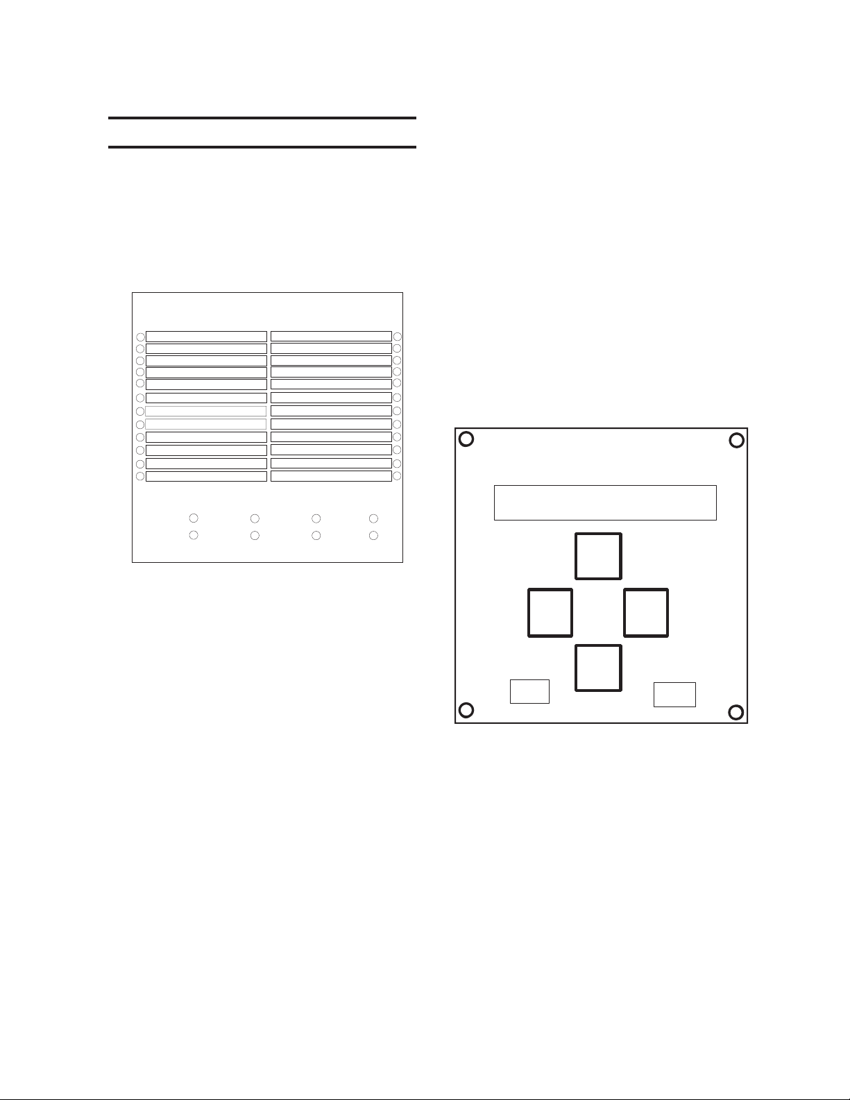
M-3425A Instruction Book
1.3 Accessories
M-3925A Target Module
The optional target module, shown below, includes 24
individually labelled TARGET LEDs to indicate
operation of the functions on the front panel. Eight
individually labelled OUTPUT LEDs will be lit as long
as the corresponding output contact is picked up.
TARGETS
24 VOLTS/Hz
27 PHASE UNDERVOLTAGE
59 PHASE OVERVOLTAGE
27TN/59D/64S STATOR GND
59N/59X NEUT/GND OVERVOLT
32 DIRECTIONAL POWER
21 PHASE DISTANCE
40 LOSS OF FIELD
78 OUT OF STEP
50BF BREAKER FAILURE
50/27INADVERTENT ENRGNG
60FL V.T. FUSE LOSS
PHASE OVERCURRENT 50
PHASE OVERCURRENT 51V
NEUTRAL O/C 50N/51N
SPLIT PHASE DIFF 50DT
STATOR OVERLOAD 49
NEG SEQ OVERCURRENT46
FIELD GND/BRUSH LIFT64F/B
FREQUENCY 81/81R/81A
PHASE DIFF CURRENT 87
GND DIFF/DIR O/C 87GD/67N
TRIP CIRCUIT MONITOR TC
IPS LOGIC LOGIC
OUTPUTS
OUT 1
OUT 2
OUT 3
OUT 4
OUT 5
OUT 6
OUT 7
OUT 8
M-3933/M-0423 Serial Communication Cables
The M-3933 cable is a 10-foot RS-232 cable for use
between the relay’s rear panel (COM2) port and a
modem. This cable has a DB25 (25-pin) connector
(modem) and a DB9 (9-pin) at the relay end.
The M-0423 cable is a 10-foot null-modem RS-232
cable for direct connection between a PC and the
relay’s front panel COM1 port, or the rear COM2
port. This cable has a DB9 (9-pin) connector at
each end.
M-3931 HMI (Human-Machine Interface) Module
The optional HMI module provides the means to
interrogate the relay and to input settings, access
data, etc. directly from the front of the relay. Its
operation is described in detail in Section 3.1, Front
Panel Controls.
BECKWITH ELECTRIC CO.
M-3425A
Figure 1-1 M-3925A Target Module
a
a
a
a
EXIT
Figure 1-2 M-3931 Human-Machine
Interface (HMI) Module
M-3801D IPSplot®
Software Package
The IPSplot
runs in conjunction with the IPScom
Communications Software on any IBM
PC-compatible computer, enabling the plotting,
printing, and analysis of waveform data downloaded
from the M-3425A Generator Protection Relay.
PLUS
Oscillograph Analysis
PLUS
Oscillograph Analysis Software
ENTER
®
1–4
Page 52

Application – 2
22
2
22
2.1 Configuration ............................................................................... 2–1
2.2 System Diagrams ....................................................................... 2–7
2.3 Setpoints and Time Settings ................................................... 2–13
ApplicationApplication
Application
ApplicationApplication
Chapter Two is designed for the person or group
responsible for the application of the M-3425A
Generator Protection Relay. It includes functional
and connection diagrams for a typical application of
the relay; and describes the configuration process
for the unit (enabling functions), output contact
assignment and input blocking designation. It also
illustrates the definition of system quantities and
equipment characteristics required by the protective
relay, and describes the individual function settings.
Menu screens in the following examples are as they
would appear on units equipped with the M-3931
Human Machine Interface (HMI) Module. The same
setting may be entered remotely using M-3820D
IPScom® Communications Software (see Chapter
4, Remote Operation).
2.1 Configuration
Configuration of the relay consists of enabling the
functions for use in a particular application,
designating the output contacts each function will
operate, and which control/status inputs will block
the function. The choices include eight programmable
output contacts (OUT1–OUT8) and six control/status
inputs (IN1–IN6), or OUT9–23 and IN7–14 for units
purchased with expanded I/O, plus a block choice
for fuse loss logic operation (see Section 2.3,
Setpoint and Time Settings, 60FL Fuse Loss
subsection for details).
The blocking control/status inputs and output contact
assignments must be chosen before entering the
settings for the individual functions. Both may be
recorded on the Relay Configuration Table in
Appendix A, Configuration Record Forms.
2–1
Page 53
M-3425A Instruction Book
Control/status input IN1 is preassigned to be the
52b breaker status contact. If a multiple breaker
scheme is used, the control/status input IN1 must
be the series combination of the “52b” breaker
contacts. Additional user-chosen control/status
inputs may initiate actions such as breaker failure,
initiate external fuse loss detection, or trigger the
oscillograph recorder.
■ NOTE: Uppercase text indicates selection.
27#1 PHASE UNDERVOLTAGE
disable ENABLE
This menu designation is required for each relay function. After enabling
the function, the user is presented with the two following screens:
This submenu item assigns the blocking designations (up to six, plus
27#1 BLOCK INPUT
fl i6 i5 i4 i3 i2 I1
fuse-loss logic) for the enabled function. “OR” logic is used if more than
one input is selected.
This submenu item assigns the output contacts (up to eight) for the
27#1 RELAY OUTPUT
o8 o7 o6 o5 o4 o3 o2 O1
particular relay function. If no output contacts are assigned, the function
will not generate any output or targets even though the function is enabled.
■ NOTE: Units with expanded I/O can only set OUT9–OUT23 and
IN7–IN14 using IPScom®.
Profiles
Up to four setpoint profiles may be used. Each
profile contains a complete set of function
configuration and settings. One of the four profiles
may be designated as the Active Profile, which will
contain the settings that the relay will actively use.
The Active Profile may be chosen manually or by
contact input. When the profile Switching Method is
set to Manual, the HMI, remote communications or
one of the IPSlogic elements will select the Active
Profile. When the Switching Method is set to Input
Contact, the profile is selected by the input contacts.
When Input Contact is selected, only the input
contacts can switch the relay’s profile, and none of
the Manual methods will switch the profile.
A Copy Profile feature is available. This feature
copies an image of the Active Profile to any one of
the other three profiles. This feature can speed up
the configuration process. Consider, for example, a
situation where a breaker will be removed from
service. Two profiles will be used: an “In Service”
profile (Profile 1), and an “Out of Service” profile
(Profile 2).
Profile 2 will be identical to the “In Service” profile,
with the exception of the overcurrent settings.
Profile 1 is set to be the Active Profile, and all
setpoints entered. An image of Profile 1 will then be
copied to Profile 2 with the Copy Active Profile
command. Profile 2 is then selected as the Active
Profile, and the overcurrent setpoints modified.
The relay allows the user to designate up to six
logic functions which perform similarly to internal
relay functions, using IPSlogic
TM
. These external
functions may be enabled or disabled, and output
contacts and blocking control/status inputs are
chosen the same as for the internal functions. The
external functions are described in further detail in
Section 2.3, Setpoint and Time Settings, IPSlogic
subsection.
Functions
Configuration of the relay consists of enabling the
functions for use in a particular application,
designating the output contacts each function will
operate, and which control/status inputs will block
the function. The choices include eight programmable
output contacts (OUT1–OUT8) and six control/status
inputs (IN1–IN6)/(OUT1–OUT23 and IN1–IN14 for
expanded I/O units) plus a block choice for fuse
loss logic operation (see Section 2.3, Setpoint and
Time Settings, 60FL Fuse Loss subsection for
details.)
Control/status inputs may also initiate actions, such
as Breaker Failure Initiate, Trigger Oscillograph
Recorder, Switch Setpoint Profile, or initiate an
IPSlogic function. The control/status inputs and
output contacts need to be chosen before configuring
the individual functions. Both can be recorded on
the Relay Configuration Table in Appendix A, Forms.
Special Considerations
Control/status input IN1 is preassigned to be the
52b breaker contact. IN5 and IN6 may be used to
select setpoint profiles.
Outputs 1–6 and 9–23 are form “a” contacts (normally
open), and outputs 7 and 8 are form “c” contacts
(center tapped “a” and “b” normally closed) contacts.
Output contacts 1–4 contain special circuitry for
high-speed operation and pick up 4 ms faster than
outputs 5–8. Function 87 outputs are recommended
to be directed to OUT1 through OUT4 contacts.
▲ CAUTION: During profile switching, relay operation
is disabled for approximately 1 second.
2–2
Page 54
Application – 2
Relay System Setup
The system setup consists of defining all pertinent
information regarding the system quantities. Setup
screens shown here may be accessed through the
SYSTEM SETUP menu. Regardless of the functions
that are enabled or disabled, all System Setup
5tupnI 6tupnI noitceleS
nepOnepO1eliforP
desolCnepO2eliforP
nepOdesolC3eliforP
desolCdesolC4eliforP
Table 2-1 Input Activated Profile
INPUT ACTIVATED PROFILES
disable enable
ACTIVE SETPOINT PROFILE
________
COPY ACTIVE PROFILE
TO_PROFILE_1
When Input Activated Profiles is disabled, the Active Profile can be
selected using HMI or remote communication. When enabled, the
Active Profile is selected by the state of Input 5 and 6 (see Table 2-1).
This screen sets the active setpoint profile.
This screen initiates a copy of the Active Profile to any one of the
other profiles.
values are required to be input. Several functions
require proper setting of these values for correct
operation. The Nominal Voltage and Nominal Current
settings are needed for proper normalization of per
unit quantities. CT and VT ratios are used only in
monitoring and displaying system primary quantities.
NOMINAL VOLTAGE
________ Volts
NOMINAL CURRENT
________ Amps
VT CONFIGURATION
line-line line-ground
line-gnd_to_line-line
DELTA-Y TRANSFORM
dis delta_ab delta_ac
The secondary VT voltage when primary voltage is equal to the
rated
generator
VT connections. V
voltage. V
nominal
=( V gen rated $ VT ratio) for L-L
nominal
=(Vgen rated $ (S3 VT ratio)) for L-G VT
connections.
The secondary CT current of the phase CT’s with rated
generator
current. I nom = (VA $ (Vgen rated(S3) )(CT ratio) )
Indicates VT connection. (See Figure 2-7, Three-Line Connection Diagram.)
When line-ground voltages are used, functions 24, 27, and 59 may
operate for line-ground faults. If this is not desired, the line-gnd-toline-line selection should be used to prevent operation of these functions
for line-ground faults.When line-gnd-to-line-line is selected, the relay
internally calculates line-line voltages from line-ground voltages for all
voltage-sensitive functions. This line-gnd-to-line-line selection should
be used only for a VT line-to-ground nominal secondary voltage of
69V (not for 120 V). For this selection, the nominal voltage setting
entered should be line-line nominal voltage, which is S3 times line-ground
nominal voltage, and voltage function pickup setpoints calculation should
be made using line-to-line voltage.
When the generator is connected through a Delta-Y (delta ab or delta
ac) unit transformer, the relay will internally consider the 30° phase
shift for 51V and 21 functions.
PHASE ROTATION
a-c-b a-b-c
This screen allows the user to select the phase rotation of the M-3425A
to match the generator.
2–3
Page 55
M-3425A Instruction Book
59/27 MAGNITUDE SELECT
rms dft
50DT SPLIT-PHASE DIFF
disable enable
PULSE RELAY
o8 o7 o6 o5 o4 o3 o2 o1
This screen allows the selection of RMS or DFT for the 59 and 27
functions. The magnitude can be selected as the RMS of the total
waveform (including harmonics) or the RMS of the 60/50 Hz fundamental
component of the waveform using the Discrete Fourier Transform (DFT).
When the RMS option is selected, the magnitude calculation is accurate
over a wide frequency range (10 to 80 Hz) and the accuracy of the time
delay is +20 cycles. When the DFT option is selected, the magnitude
calculation is accurate near 50 or 60 Hz and the timer accuracy is &1
cycle. When a wider frequency response is needed, select RMS. For
generator protection applications, it is recommended to use the RMS
selection. RMS is the default when shipped from the factory. For 59
function when positive sequence voltage is selected, the calculation uses
DFT irrespective of DFT/RMS selection.
If the 50DT function is to be used for split-phase differential protection,
this selection should be enabled. If the 50DT function is to be used as a
definite time overcurrent function, or if 50DT is not enabled, this selection
should be disabled.
If pulse relay operation is selected, output will dropout after the seal-in
delay expires, even if the condition which caused the relay to pick up is
still out of band. When selected, latching outputs are not available.
*
LATCHED OUTPUTS
o8 o7 o6 o5 o4 o3 o2 o1
RELAY SEAL-IN TIME OUT1
________ Cycles
ACTIVE INPUT OPEN/close
I6 i5 i4 i3 i2 i1
V.T. PHASE RATIO
________ : 1
V.T. NEUTRAL RATIO
________ :1
V.T. VX RATIO
________ :1
C.T. PHASE RATIO
________ : 1
If any of the outputs are selected as latched, then after tripping, this
output will stay activated, even when the tripping condition is removed.
The Latched Output can be reset using the TARGET RESET pushbutton.
When selected, Pulse Relay is not available. *
Minimum time the output contact will remain picked up to ensure proper
seal-in, regardless of the subsequent state of the initiating function. Individual Seal-In settings are available for all outputs.*
This designates the “active” state for the individual status input. Programming uppercase (see I6) causes the “active” or “operated” condition to be
initiated by the external contact opening. Otherwise, external contact closure will activate the input.*
*
■ Note: Settings for expanded I/O must be made through IPScom®.
Ratio of the phase VTs. Example: 13,800 V : 120 V =13,800/120=115:1
Ratio of the neutral VT. Example: 13,800 V : 120 V =13,800/120=115:1
Ratio of auxiliary VT. Example: 13,800 V : 120 V =13,800/120=115:1
Ratio of phase CTs. Example: 3,000:5 = 3000/5=600:1
C.T. NEUTRAL RATIO
________ : 1
2–4
Ratio of neutral CT. Example: 3,000:5 = 3000/5=600:1
Page 56
SETUP
Application – 2
SETUP SYSTEM
Nominal Frequency: 60 Hz C.T. Secondary Rating: 5A
Nominal Voltage: 120
Nominal Current: 5.00
Input Active State:
V.T. Configuration:
59/27 Mag. Select:
Phase Rotation:
V.T. Phase Ratio:
V.T. Neutral Ratio:
V.T. VX Ratio
C.T. Phase Ratio:
C.T. Neutral Ratio:
Pulse Relay
Outputs:
Latched Outputs
Injection Frequency for F64S: 20 Hz
1 234567 8
Outputs:
50.0 V
65432 1
Open
Close
Line to Ground
RMS
ABC
1.0
1.0
1.0
10
10
1234567 8
140.0 V
6.00 A0.50 A
Open
Close
DFT
ACB
:1
1.0
1.0
:1
:1
1.0
:1
1
:1
1
Note: Pulse/Latched Relay Outputs should be selected in 2 steps
Open
Close
Line to Line Line-Ground to Line-Line
50DT
Split Phase
Differential:
i)Deselect Latched/Pulse Relay Outputs and Save
ii) Select Pulse/Latched Outputs and Save
Enable
Disable
6550.0
6550.0
6550.0
65500
65500
Delta-Y Transform
Disable
Open
Close
Relay Seal-In Time
OUT 1:
Pulse Relay Expanded Outputs
Latch Relay Expanded Outputs
Delta-AB Delta-AC
Open
Close
30
30
2:
30
3:
30
4:
5:
30
6:
30
7:
30
8:
30
Open
Close
8160
cycles
2
cycles
Input Active State Expanded
Relay Seal-In Time Expanded
8160
30
OUT 9:
10:
11:
12:
13:
14:
15:
16:
30
30
30
30
30
30
30
cycles
2
cycles
30
30
30
30
30
30
30
OUT 17
18
19
20
21
22
23
Save Cancel
Figure 2-1 Setup System Dialog Box
Path: Relay menu / Setup submenu / Setup System command
COMMAND BUTTONS
Input Active When the unit is equipped with expanded I/O, this command opens the Expanded Input Active
State State screen (Figure 2-2), to allow the selection of Expanded Inputs 7 through 14.
Expanded
Pulse/Latch When the unit is equipped with expanded I/O, this command opens the Pulse/Latch
Relay screen (Figures 2-3 and 2-4) to allow the selection of expanded outputs 9 through 23.
Expanded
Outputs
Save When connected to a protection system, sends the currently displayed information to the unit.
Otherwise, saves the currently displayed information.
®
Cancel Returns you to the IPScom
■■
■ NOTE: Checking the inputs for the Active Input Open parameter designates the “operated” state established by
■■
an
opening
rather than a closing external contact.
main window; any changes to the displayed information are lost.
2–5
Page 57
M-3425A Instruction Book
? X
Expanded Input Active State
11
12
13
14
Open
Open
Open
Open
Close
Close
Close
Close
10
7
Open
8
Open
9
Open
Open
Close
Close
Close
Close
Figure 2-2 Selection Screen for Expanded Input
Pulse Relay Expanded Outputs
OUTPUT9
OUTPUT10
OUTPUT11
OUTPUT12
OUTPUT13
OUTPUT14
OUTPUT15
OUTPUT16
OUTPUT17
OUTPUT18
OUTPUT19
OUTPUT20
OUTPUT21
OUTPUT22
OUTPUT23
OK
Cancel
?X
OK
Cancel
2–6
Figure 2-3 Pulse Relay Expanded Output Screen
?X
Latch Relay Expanded Outputs
OUTPUT9
OUTPUT10
OUTPUT11
OUTPUT12
OUTPUT13
OUTPUT14
OUTPUT15
OUTPUT16
OUTPUT17
OUTPUT18
OUTPUT19
OUTPUT20
OUTPUT21
OUTPUT22
OUTPUT23
OK
Cancel
Figure 2-4 Latch Relay Expanded Output Screen
Page 58
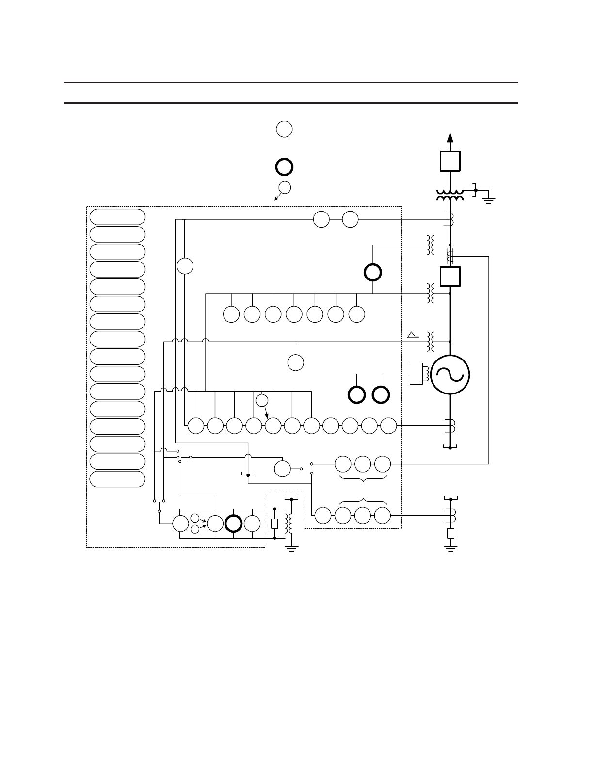
2.2 System Diagrams
Application – 2
M-3425A
Targets
(Optional)
Integral HMI
(Optional)
Metering
Waveform Capture
IRIG-B
Front RS232
Communication
Rear RS232
Communication
Rear Ethernet
Port (Optional)
Rear RS-485
Communication
Multiple Setting
Groups
Programmable I/O
Self Diagnostics
Dual Power Supply
(Optional)
Breaker
Monitoring
Trip Circuit
Monitoring
Event Log
3VO (Calculated)
59D Line S ide
Voltage
(Software Select)
M-3425A Typical
Connection Diagram
87
60
FL
3VO (Calculated)
V
X
V
67N Polari zation
N
(Software Sele ct)
V
X
27
59D
27
TN
32
These functions are available in
the Comprehensive Package. A
subset of these functions are also
available in a Base Package.
This function is available as a
optional protective function.
This function provides control for
the function to which it points.
50
BFPh
81R 81 27 59 24
81A
(Note 3)
59X
27
51V 50 /27
67N Oper ating Current
(Software Sel ect)
I
N
3I
O
87
GD
64S
59N
67N
R
50
BFN
50
BFN
50
DT
(Metering)
492132 504078
25
M
64F 64B
46
50N
51N
(Note 5)
50N
51N
M
(Metering)
Utility System
52
Unit
CT
VT (Note 1 )
52
VT
Gen
VT (Note 1 )
M-3921
+
-
CT
R
CT (Residual)
(Note 4)
CT (Neutral)
(Notes 2 & 5 )
High-impedance Grounding with Third
Harmonic 100% Ground Fault Protection
Low-impedance Grounding with Ground Differential
and Overcurre nt Stator Ground Fault Protection
■ NOTES:
1. When 25 function is enabled, 59X, 59D with VX and 67N with VX are not available, and vice versa.
2. When 67N function with IN (Residual) operating current is enabled, 87GD is not available, and vice
versa.
3. The 50BFN, 50N, and 51N may utilize either the neutral current or the residual current.
4. When used as a turn-to-turn fault protection device.
5. The current input IN can be either from neutral current or residual current.
6. The 50BFN, 50N, 51N, 59D, 67N (with IN or VN) and 87GD functions are unavailable when the 64S
function has been purchased. See the M-3425A Instruction Book for connection details.
Figure 2-5 One-Line Functional Diagram
2–7
Page 59
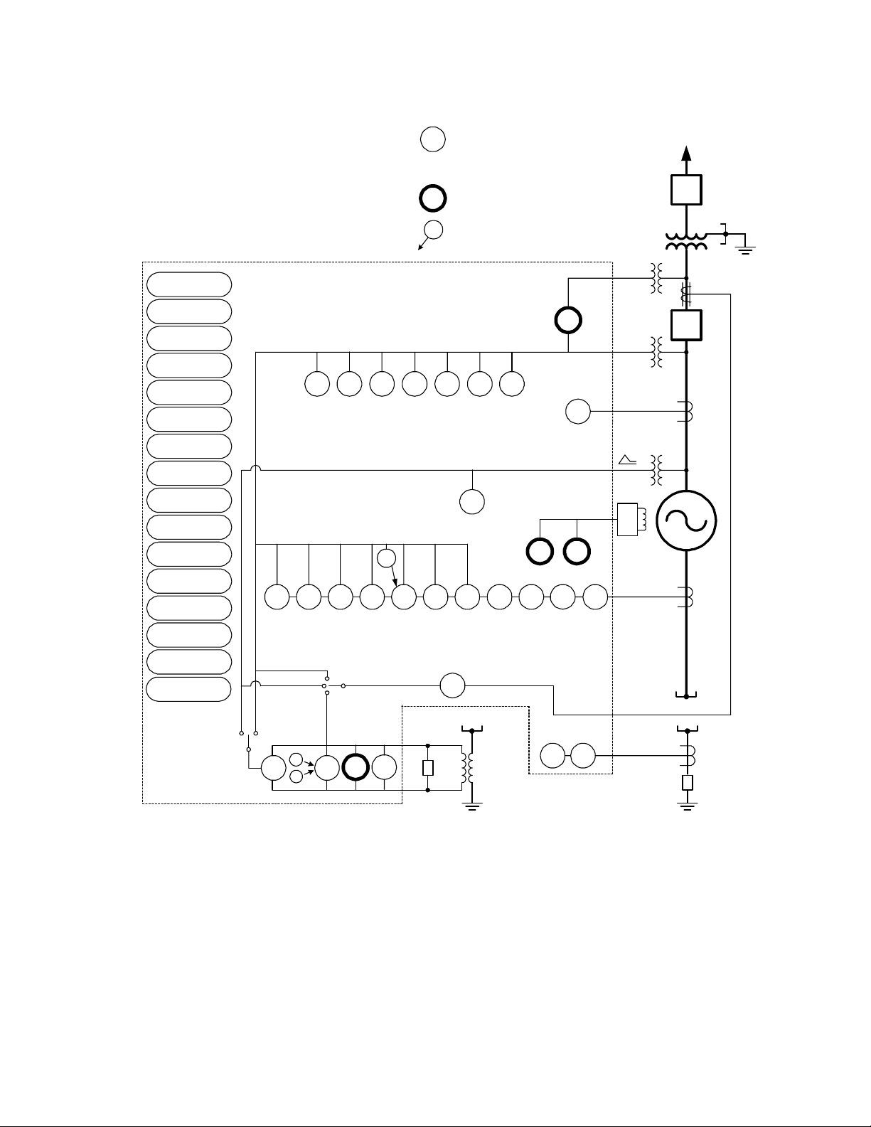
M-3425A Instruction Book
M-3425A
Targets
(Optional)
Integral HMI
(Optional)
Metering
Waveform Capture
IRIG-B
Front RS232
Communication
Rear RS232
Communication
Rear Eth ernet
Port (Optional )
Rear RS-485
Communication
Multiple Setting
Groups
Programmable I/O
Self Diagnostics
Dual Power Supply
(Optional)
Breaker
Monitoring
Trip Circuit
Monitoring
Event Log
M-3425A Typical
Connection Diagram
(Config ured for Split -Phas e Diffe rential )
81R 81 59 27 24
81A
3VO (Calculated)
V
X
V
67N Polarization
N
(Software Select)
These functions are available in
the Comprehensive Package. A
subset of these functions are also
available in a Base Package.
This function is available as a
optional protective function.
This function provides control for
the function to which it points.
25
M
(Metering)
(Note 2)
59X
27
492132 504078 60FL 51V 50/27
(Note 4)
67N
50
DT
64F 64B
46
M
(Metering)
Utility System
52
Unit
VT (Note 1)
52
VT
Gen
CT (Note 3)
VT (Note 1)
M-3921
+
-
CT
CT (Resid ual)
(Note 5)
3VO (Calculated)
V
■
NOTES:
59D L ine Side
Voltage
(Software Select)
X
27
27
59D
32
TN
64S 59N
High-impedance Grounding with Third
Harmonic 100% Ground Fault Protection
R
50N 51N
Low-impedance Grounding with
Overcurrent Stator Ground Fault Protection
CT
CT (Neutra l)
(Note 5)
R
1. When 25 function is enabled, 59, 59X, 59D with VX and 67N with VX are not available, and vice
versa.
2. When used as a turn-to-turn fault protection device.
3. CTs are connected as split-phase differential current.
4. 67N operating current can only be selected to IN (Residual) for this configuration.
5. The current input (IN) can be either from neutral current or residual current.
6. The 50BFN, 50N, 51N, 59D, 67N (with IN or VN) and 87GD functions are unavailable when the 64S
function has been purchased. See the M-3425A Instruction Book for connection details.
Figure 2-6 Alternative One-Line Functional Diagram (configured for split-phase differential)
2–8
Page 60
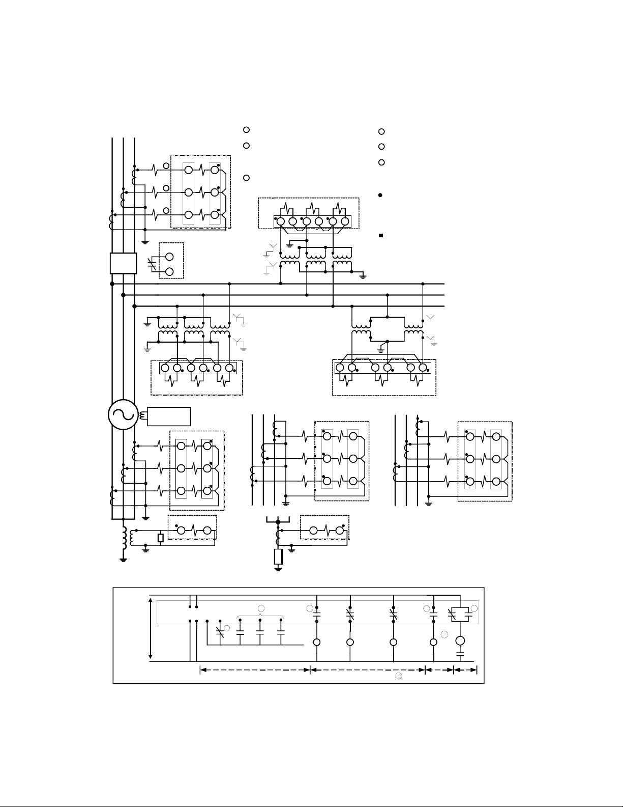
Application – 2
Generator
ABC
ABC
52
Gen
abc
Other
Relays
52b
A
B
C
Coupler Module
Other
Relays
M-3425A
1
1
1
M-3425A
10
11
M-3425A
M-3921
Field Ground
50 51
48 49
46 47
43 41 3942 40 38
M-3425A
58 59
56 57
54 55
1
2
3
Three VT Wye-Wye
Alternate Connection
Three VT Wye-Wye
OR
Wire to split phase differential CTs for
use with 50DT split phase function.
Required generator breaker status input
(52b). Contact is closed when generator
breaker is open. Use unit breaker
contact if no generator breaker present.
Output contact pairs designated by
user.
M-3425A
434139 424038
43 41 3942 40 38
Connection
abc
Other
Relays
M-3425A
M-3425A
59 58
57 56
55 54
Alarm output can be grouped to a single alarm
4
at the discretion of user.
Available control output to service other relays
5
for VT Fuse Loss can be designated.
6
Input contact number is designated by user.
WARNING: ONLY dry contact inputs must be
connected because these contact inputs are
internally wetted. Application of external
voltage on these inputs may result in
damage to the units.
NOTE: M-3425A current terminal polarity marks
(
. ) indicate "entering" current direction when
primary current is "from" the generator to the
system. If CT connections differ from those
shown, adjust input terminals.
A
B
C
Two Vt Open-Delta
Connection
abc
OR
Other
Relays
M-3425A
59 58
57 56
55 54
DC: 24V
48V
OR
DC: 110V
125V
220V
250V
AC: 110V
120V
230V
240V
M-3425A
45 44
R
High Impedance Grounding
OR
Example of Control/Output Connections
+
M-3425A
+
60 62
Power
61 63 11 10
Supply
-
-
2
BREAKER
FAILURE
INITIATE
Figure 2-7 Three-Line Connection Diagram
R
6
60FL52b
OSCILLOGRAPH
RECORDER
INITIATE
EXTERNAL
INPUTS
M-3425A
52 53
Low Impedance Grounding
3 3
ALARM
TRIP
16
15
SELF-
TEST
FAILURE
ALARM
ALARM
OUTPUTS
12
13
POWER
STATUS
ALARM
4
3
5
VT
OK
FUSE
LOSS
CONTROL
OUTPUTS
52G
52Ga
TRIP
OUTPUT
2–9
Page 61
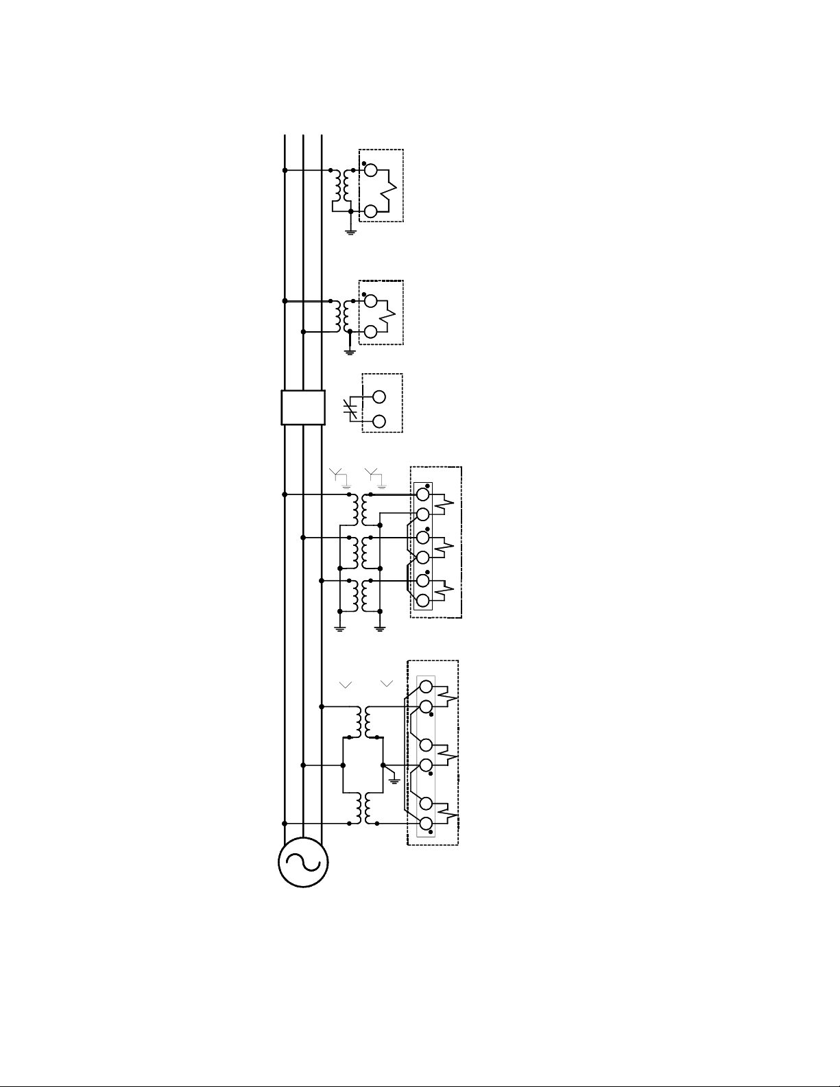
M-3425A Instruction Book
M-3425A
65
V
X
64
Used when Generator
Side VTs are connected
Line-Ground.
ABC
52
Gen
ABC
AB
C
52b
OR
M-3425A
65
V
X
64
M-3425A
10
11
Used for Sync Check (25)
V
X
Used when Generator Side VTs
are connected Line-Line
M-3425A
39
38
41
40
43
42
Three VT Wye-Wye
Connection
OR
M-3425A
42
43
Two VT Open-Delta
Connection
40
41
38
39
Generator
■ NOTE: When VX is connected for Sync Check function (25), turn-to-turn fault protection (59X) is not
available.
Figure 2-8 Function 25 Sync Check Three-Line Connection Diagram
2–10
Page 62
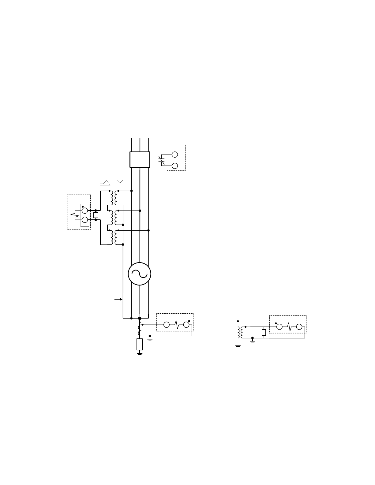
Application – 2
M-3425A
V
X
65
64
VX used for turn-to-turn
fault protection (59X)
Line to Neutral
Voltage Rated
R
Cable
ABC
52
Gen
ABC
abc
52b
Generator
M-3425A
M-3425A
10
11
52 53
OR
M-3425A
45 44
R
R
Low Impedance Grounding
High Impedance Grounding
■ NOTE: When VX is connected for turn-to-turn fault protection, 59X and 25 functions are not available.
Figure 2-9 Function 59X Turn to Turn Fault Protection Three-Line Connection Diagram
2–11
Page 63
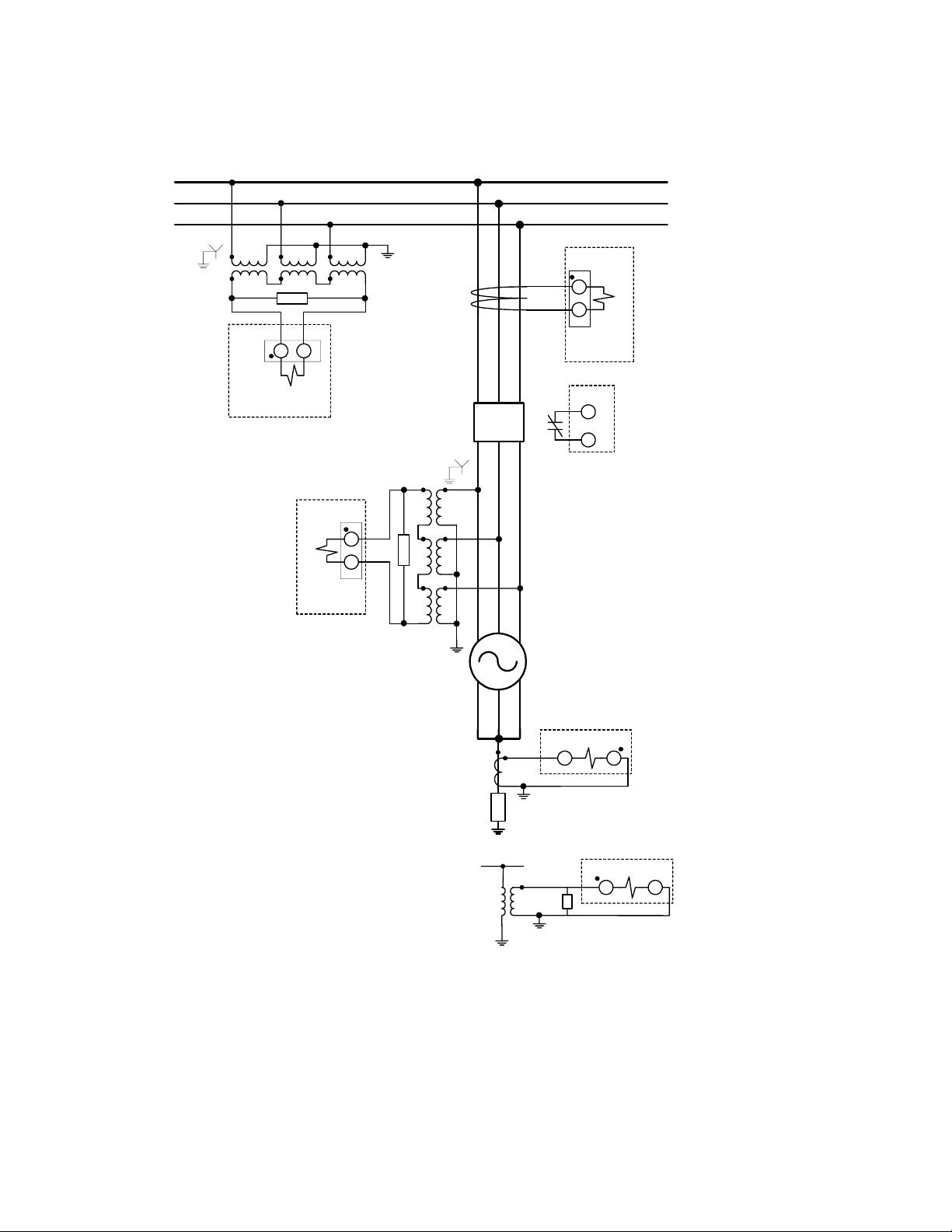
M-3425A Instruction Book
M-3425A
Bus Section
R
65 64
59X
Bus Ground
M-3425A
V
X
67N, 59D
Connection
A
B
C
M-3425A
52b
53
52
67N
Connection
M-3425A
10
11
Residual CT
ABC
52
Gen
ABC
65
64
R
I
input can be connected
N
either at Neutral or as Residual.
VX can be used for both 67N and
59D if connected in this manner.
abc
Generator
M-3425A
R
Low Impedance Gr ounding
52 53
I
input can be connected
N
either at Neutral or as Residual.
OR
M-3425A
45 44
R
High Impedance Grounding
■ NOTE: When VX is connected for bus ground protection (59X, 67N, or 59D) , 25 function is not available.
Figure 2-10 Function 67N, 59D, 59X (Bus Ground) Three-Line Connection Diagram
2–12
Page 64
Application – 2
2.3 Setpoints and Time Settings
The individual protective functions, along with their magnitude and timing settings are described in the
following pages. Settings for disabled functions do not apply. Some menu and setting screens do not appear
for functions that are disabled or not purchased. Menu screens are as they would appear on units equipped
with the M-3931 HMI Module. The same setting may be entered using M-3820D IPScom Communications
Software.
For those units equipped with Expanded I/O, setting of Expanded Inputs and Outputs is accomplished by
selecting “Expanded I/O” from the individual function screen. IPScom® will display the Expanded I/O
Initiate dialog screen (Figure 2-11).
?X
Expanded Output Initiate
OUTPUT9
OUTPUT10
OUTPUT11
OUTPUT12
OUTPUT13
OUTPUT14
OUTPUT15
OUTPUT16
OUTPUT17
OUTPUT18
OUTPUT19
OUTPUT20
OUTPUT21
OUTPUT22
OUTPUT23
Expanded Input
Initiate
Input 7
Input 8
Input 9
Input 10
Input 11
Input 12
Input 13
Input 14
Cancel
Figure 2-11 Selection Screen for Expanded I/O Initiate
OK
2–13
Page 65

M-3425A Instruction Book
21 Phase Distance
The Phase Distance function (21) is designed for
system phase fault backup protection and is
implemented as a three-zone mho characteristic.
Three separate distance elements are used to detect
AB, BC, and CA fault types. The ranges and
increments are shown in Figure 2-14. The diameter,
offset, system impedance angle (relay characteristic
angle), and definite time delay need to be selected
for each zone for coordination with the system
relaying in the specific application.
Zone 1, Zone 2 and Zone 3 may be used for backup
protection for unit transformer and transmission
faults. Zone 3 in conjunction with Zone 2 can be
used to detect an Out of Step condition and it can
be programmed to block Function 21 #1 and/or 21
#2. If Zone 3 is being used for out-of-step blocking,
it does not trip.
If Zone 1 is not set to see the transmission system,
out-of-step blocking is not recommended.
When Zone 3 is used for Out-of-step blocking, the
out of step delay is used for the detection of the
transit time of the swing between Zone 3 and Zone
2 impedances.
The load encroachment blinder function can be set
with a reach and an angle as shown in Figure 2-13.
When enabled, this feature will block the 21 Function
from misoperating during high load conditions.
When the generator is connected to the system
through a delta/wye transformer, proper voltages
and currents (equivalent to the high side of the
transformer) must be used in order for the relay to
see correct impedances for system faults. By
enabling the Delta-Y Transform feature (see Section
2.1, Configuration, Relay System Setup), the relay
can internally consider the 30° phase shift (30° lead
delta-ab or 30° lag delta-ac) through the delta/wye
transformer, saving auxiliary VTs. Impedance
calculations for various VT connections are shown
in Table 2-2. All impedance settings are secondary
relay quantities and can be derived from the following
formula:
= Z
Z
SEC
where Z
= primary impedance, RC = current transformer
x (RC ÷ RV)
PRI
= secondary reflected impedance, Z
SEC
PRI
ratio, and RV = voltage transformer ratio.
The minimum current sensitivity depends on the
programmed reach (diameter and offset). If the
current is below the minimum sensitivity current,
the impedance calculated will saturate, and not be
accurate. This will not cause any relay misoperation.
An overcurrent supervision feature can be enabled,
which will block the 21 function when all three
phase currents are below the pickup value.
21 #1 DIAMETER
________ Ohms
21 #1 OFFSET
________ Ohms
21 #1 IMPEDANCE ANGLE
________ Degrees
21#1 LOAD ENCROACHMENT
disable ENABLE
21 #1 LOAD ENCR ANGLE
________ Degrees
21 #1 LOAD ENCR R REACH
________ Ohms
Typically the first zone of protection is set to an impedance value
enough in excess of the first external protective section (typically
the unit transformer) to assure operation for faults within that
protective zone. See Figure 2-12, Phase Distance (21) Coverage.
A negative or positive offset can be specified to offset the mho
circle from the origin. This offset is usually set at zero. See Figure
2-13, Phase Distance (21) Function Applied For System Backup.
The impedance angle should be set as closely as possible to the
actual impedance angle of the zone being protected.
When enabled the 21 Function is blocked when the impedance falls
within the zone but above the R Reach and below the Load Encroachment angle.
■ NOTE: The 21 #2 and #3 zone settings can be set for an additional
external section of protection on the system (typically
transmission Zone 1 distance relays) plus adequate
overreach. #2 and #3 screens are identical to those in #1.
Element #3 also includes out-of-step time delay when outof-step blocking is enabled for Zone #1 and/or Zone #2.
2–14
Page 66
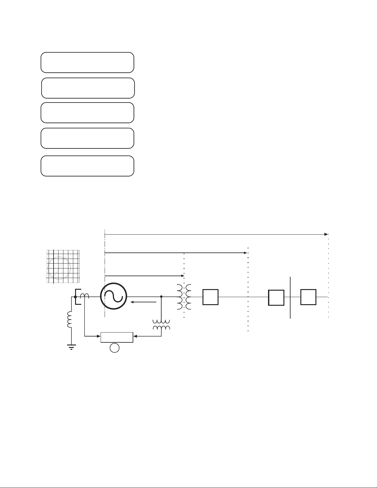
Application – 2
21 #1 OC SUPERVISION
disable enable
21 #1 OC SUPERVISION
________ Amps
21 #1 OUT OF STEP BLOCK
disable enable
21 #1 DELAY
________ Cycles
21 #3 OUT OF STEP DELAY
________ Cycles
Protected Range Zone 3
When enabled, the overcurrent supervision blocks the 21 Function
when all three phase currents are below the pickup.
When enabled the 21 Function is blocked on the detection of an
out-of-step condition.
The time delays are set to coordinate with the primary protection of
those overreached zones and, when applicable, with the breaker
failure schemes associated with those protective zones.
In Zone #3 when out-of-step blocking is enabled for Zone #1 or #2.
+X
–R
–X
+R
Protected Range Zone 2
Protected Range Zone 1
3
52
52
52
Bus
M-3425A
21
Figure 2-12 Phase Distance (21) Coverage
■ NOTE: The reach settings of the distance elements (21) should not include generator impedance since
the distance measurement starts at the VT location. However, since the neutral side CTs are
used for this function, backup protection for generator Phase-to-Phase faults is also provided
2–15
Page 67
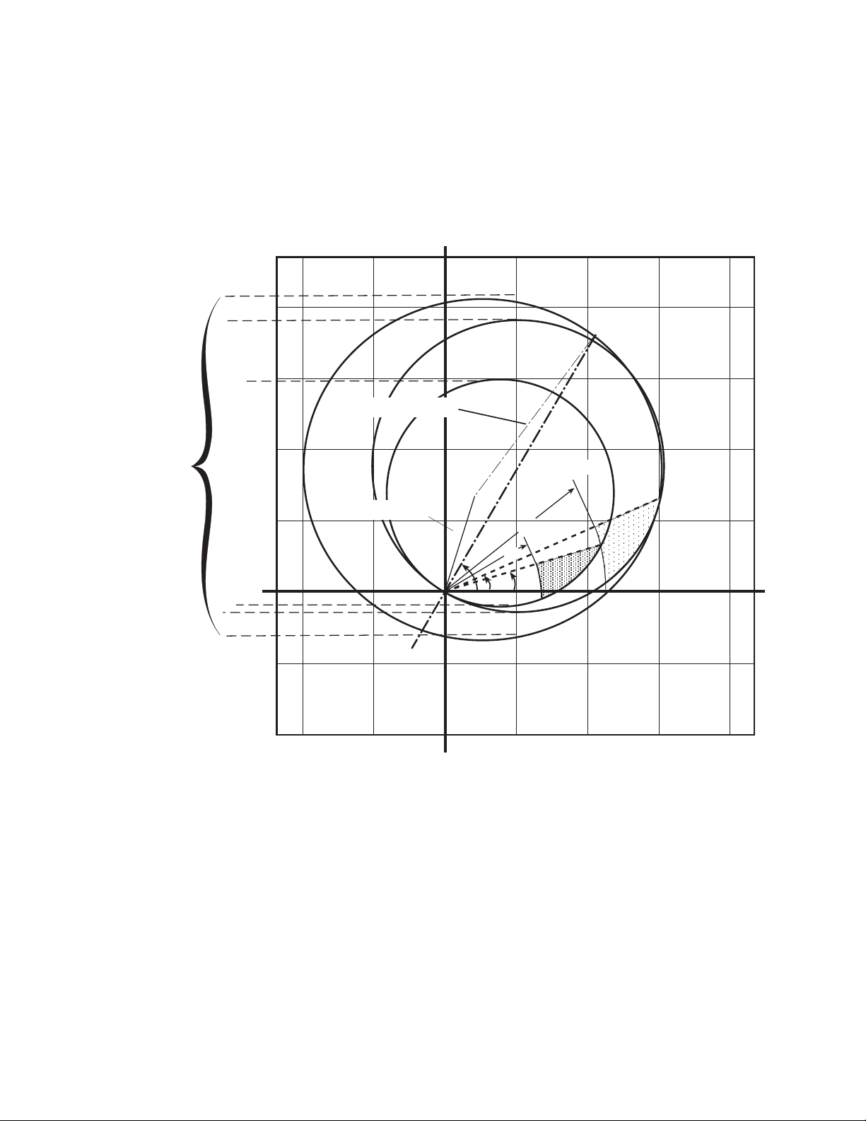
M-3425A Instruction Book
+jX
ZONE 3
Circle
Diameters
–R
Transmission Line
Unit Transformer
–jX
ZONE 2
ZONE 1
R2
R1
Θ
δ 2
Block
δ 1
Block
+R
R1 Zone 1 Load Encroachment Blinder R Reach
R2 Zone 2 Load Encroachment Blinder R Reach
δ1 Zone 1 Load Encroachment Blinder Angle
δ2 Zone 2 Load Encroachment Blinder Angle
Θ Impedance Angle Setting
■ NOTE: Zone #3 is used for power swing detection in this example.
Figure 2-13 Phase Distance (21) Function Applied for System Backup
2–16
Page 68
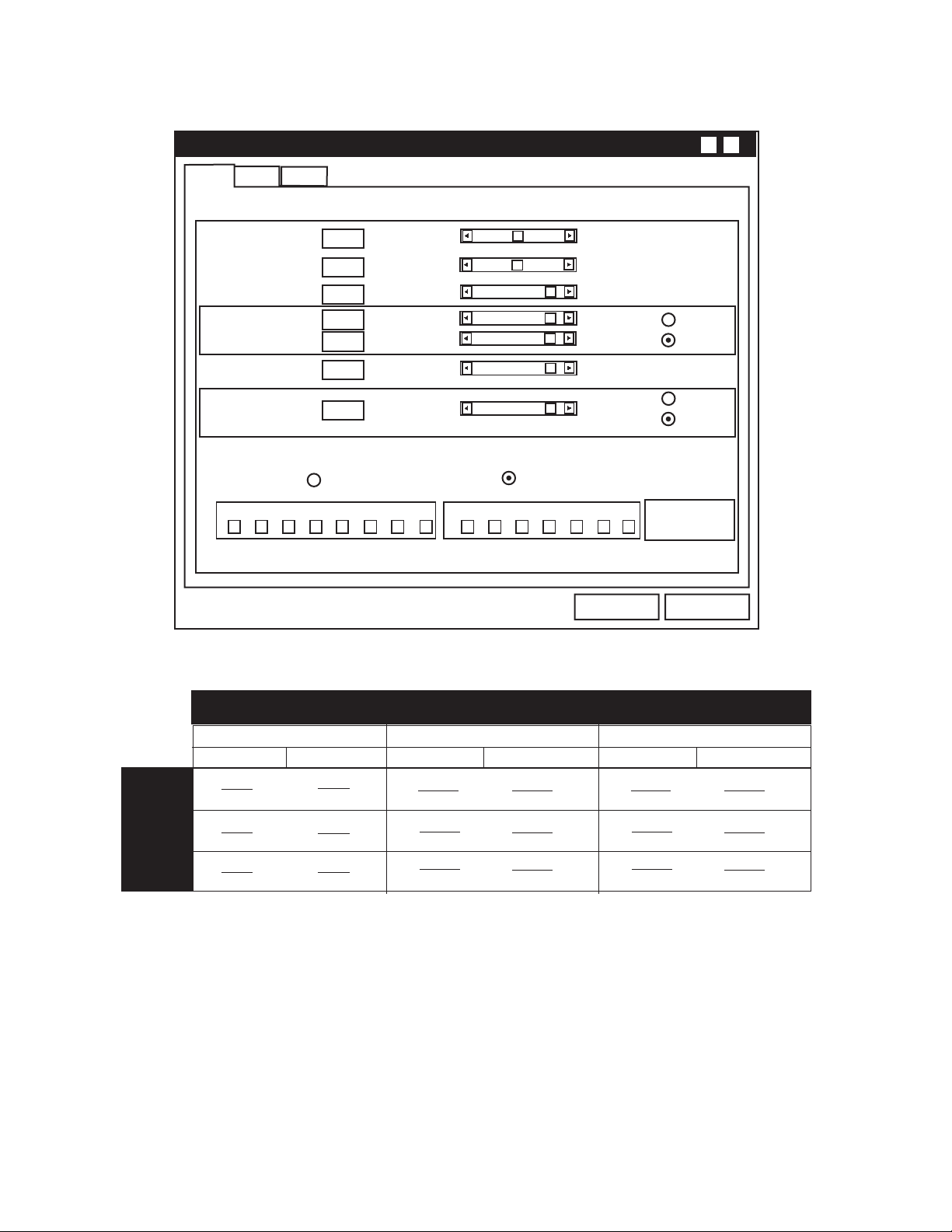
Application – 2
X?
#1 #2
#3
(21) PHASE DISTANCE
Circle Diameter:
Offset:
Impedance Angle:
Load Encr. Angle:
Load Encr. R Reach:
Delay:
Overcurrent SV:
Out of Step Block Enable
OUTPUTS
8765432 1 FL654321
@ : WARNING, You have not selected an output!
0.1 Ohm
-100.0 Ohm(s)
1°
0.1 Ohm
1 Cycle
0.1 A
@
0°
Out of Step Block Disable
Blocking Inputs
100.0 Ohm(s)
100.0 Ohm(s)
90°
90°
100.0 Ohm(s)
8160 Cycles
20 A
Save
Enable
Disable
Enable
Disable
Expanded I/O’s
Cancel
AB Fault
BC Fault
CA Fault
Transformer Direct
VT Connection
L-L or L-G to L-L
V
AB
I a I
b
V
BC
I b I
c
V
CA
I c I
a
Figure 2-14 Phase Distance (21) Setpoint Ranges
Connected
L-G
VA V
I a I
VB V
I b I
VC V
I c I
Transformer Delta-AC Connected
VT Connection
L-L or L-G to L-L
B
b
C
c
A
a
VBC V
( 3 ) I
VCA V
( 3 ) I
VAB V
( 3 ) I
AB
b
BC
c
CA
a
L-G
VB V
VC V
VA V
0
I
b
0
I
c
0
I
a
Transformer Delta-AB Connected
L-L or L-G to L-L
VAB V
VBC V
VCA V
Table 2-2 Impedance Calculation
VT Connection
CA
( 3 ) I
a
AB
( 3 ) I
b
BC
( 3 ) I
c
L-G
Va V
Vb V
Vc V
0
I
a
0
I
b
0
I
c
2–17
Page 69

M-3425A Instruction Book
24 Overexcitation Volts/Hz
The Volts-Per-Hertz function (24) provides
overexcitation protection for the generator and unitconnected transformers. This function incorporates
two definite time elements which can be used to
realize traditional two-step overexcitation protection.
In addition, the relay includes an inverse time
element that provides superior protection by closely
approximating the combined generator/unit
transformer overexcitation curve. Industry standard
inverse time curves may be selected along with a
linear reset rate which may be programmed to
match specific machine cooling characteristics.
The percent pickup is based on the Nominal Voltage
setting and the nominal frequency. The V/Hz function
provides reliable measurements of V/Hz up to 200%
for a frequency range of 2–80 Hz. The ranges and
increments are presented in Figure 2-16.
Setting this relay function involves determining the
desired protection levels and operating times. The
first step is to plot the combined generator and
associated unit transformer overexcitation capability
limits. This data is typically available from the
manufacturer and should be plotted on the same
voltage base. Depending on the resulting
characteristic, one of the four families of inverse
time curves (as shown in Appendix D, Inverse
Time Curves) can be matched to provide the
protection. The two definite time elements can be
used to further shape the protection curve or provide
an alarm.
Figure 2-15 illustrates a composite graph of generator
and transformer limits, a chosen inverse time curve
and pickup, and a definite time pickup and delay.
24DT #1 PICKUP
________ %
24DT #1 DELAY
________ Cycles
24DT #2 PICKUP
________ %
24DT #2 DELAY
________ Cycles
24IT PICKUP
________ %
24IT CURVE
crv#1 crv#2 crv#3 crv#4
Definite time setpoint #1 establishes the V/Hz level above which the
protection operating time will be fixed at the definite time delay #1.
Delay time #1 establishes the operation time of the protection for all
V/Hz values above the level set by definite time setpoint #1.
Definite time setpoint #2 could be programmed to alarm, alerting the
operator to take proper control action to possibly avoid tripping.
Time to operation at any V/Hz value exceeding Definite time setting
#2.
The pickup value is the V/Hz value at which the chosen inverse
curve begins protective operation. Typical value is 105%.
Allows the user to designate the appropriate curve family for this
protection application. These curves are shown in Appendix D, Inverse
Time Curves.
24IT TIME DIAL
________
24IT RESET RATE
________ Seconds
2–18
The appropriate curve in the family is designated by the associated
“K” value of the curve.
The value entered here should be the time needed for the unit to
cool to normal operating temperature if the V/Hz excursion time
was just under the trip time.
Page 70
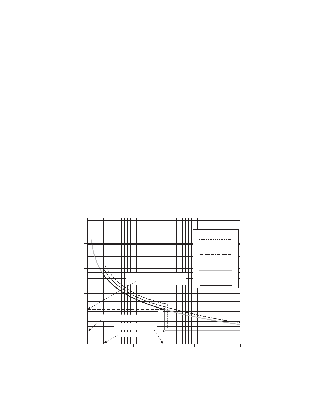
Application – 2
M-3425A Firmware Versions D-0114VXX.XX.XX
and Earlier
■ NOTE:
When the inverse time element is
enabled, the definite time element #1
must be enabled which will provide
definite minimum time setting for the
inverse time curve.
The following steps must be followed when setting
the inverse time element and definite time element
#1:
1. The pickup of the inverse time element
must be less than the pickup of the
definite time element #1
2. The operating time of the inverse time
element at the definite time element #1
pickup should be greater than the definite
time element #1 time delay setting
(A2>A1 in Figure 2-15).
3. When the inverse time element is
enabled, definite time element #1 should
not be used for alarm. Only definite time
element #2 can be used for alarm.
After any V/Hz excursion, cooling time must also
be taken into account. If the unit should again be
subjected to high V/Hz before it has cooled to
normal operating levels, damage could be caused
before the V/Hz trip point is reached. For this
reason, a linear reset characteristic, adjustable to
take into account the cooling rate of the unit, is
provided. If a subsequent V/Hz excursion occurs
before the reset characteristic has timed out, the
time delay will pick up from the equivalent point (as
a %) on the curve. The Reset Rate setting entered
should be time needed for the unit to cool to normal
operating temperature if the V/Hz excursion time
was just under the trip point.
M-3425A Firmware Version D-0150V 01.00.34
The inverse time element has a definite minimum
time of 30 cycles. Definite Time Element #1 is
independent, and has no effect on inverse time
elements.
M-3425A Firmware Version D-0150V 01.04.00
The inverse time element has a definite minimum
time of 60 cycles. Definite Time Element #1 is
independent, and has no effect on inverse time
elements.
1000
Generator Limit Curve
100
10
Inverse Time Delay at Definite
Time Pickup #1 (A2)
1
Time in Minutes
0.1
0.01
100 105 110 115 120 125 130 135 140 145 150
Definite Time Delay (A1)
Definite Time Pickup
Inverse Time Pickup
Percentage Volts/Hz
A2
A1
Transformer Limit Curve
on Generator Base
Inverse Square Curve
Combined Protection
K = 5
Curve
Figure 2-15 Example of Capability and Protection Curves (24)
2–19
Page 71
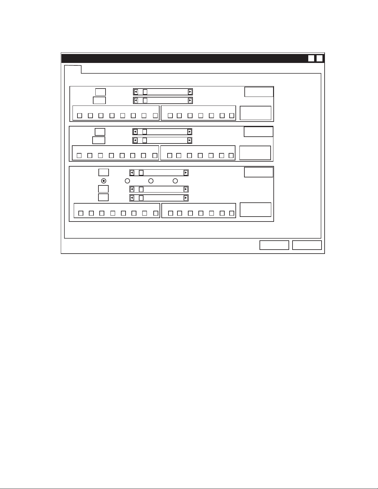
M-3425A Instruction Book
F24
X?
(24) - VOLTS/HZ
Pickup:
Delay:
8765432 1
Pickup:
Delay:
8765432 1
Pickup:
Curves: #1 #2 #3 #4
Time Dial:
Reset Rate:
8765432 1
@ : WARNING, You have not selected an output!
100%
30 Cycles
@
100%
30 Cycles
@
100% 200%
1
1 Sec
@
Figure 2-16 Volts-Per-Hertz (24) Setpoint Ranges
200%
8160 Cycles
Blocking InputsOUTPUTS
FL654321
200%
8160 Cycles
Blocking InputsOUTPUTS
FL 6 5 4 3 2 1
100
999 Secs
Blocking InputsOUTPUTS
FL654321
Def. Time #1
Expanded I/O’s
Def. Time #2
Expanded I/O’s
Inv. Time
Expanded I/O’s
Save
Cancel
2–20
Page 72

25 Sync Check
■ NOTE: The 25 function cannot be enabled under
any one of the following conditions:
• 67N (Residual Directional Overcurrent)
is enabled and the polarizing quantity
has been set to V
.
X
• 59D is enabled and the line side voltage
is set to VX.
• 59X is connected for turn-to-turn fault
protection or bus ground protection.
The Synchronism (Sync) Check function (25) is
used to ensure that the voltage magnitude, phase
angle and frequency of the generator (V1) and the
utility system (VX) are within acceptable limits before
the generator is synchronized with the system.
Generator voltage (V1) can be selected as A, B, or
C (line-to-ground and line-ground to line-line) or AB,
BC, or CA (line-to-line).
The sync check function includes phase angle,
delta frequency, and delta voltage checks.
Phase Angle Check
The phase angle is considered acceptable when
the selected sync phase voltage (V1) and system
voltage (VX) are within the Upper Volt Limit and
Lower Volt Limit window and the measured phase
angle is within the phase angle window.
Phase angle window is defined as twice the Phase
Angle Limit setting. For example, if the Phase
Angle Limit is set at 10 degrees, a phase angle
window of 20 degrees exists between –10 degrees
and +10 degrees. The logic diagram of the phase
angle check is shown in Figure 2-17.
Application – 2
Dead Line/Dead Bus Check
The Dead Volt Limit defines the Hot/Dead voltage
level used in Deadline/Dead Bus closing schemes.
When the measured V
the Dead Volt Limit, V
voltage is equal to or below
X
is considered dead. When
X
the measured VX is above the Dead Volt Limit, V
is considered hot. The opposite side of the breaker
uses the positive sequence voltage measurement
(V1) for 3-phase consideration in determining hot/
dead detection. Different combinations of hot line/
dead bus closings may be selected, depending on
how the buses are referenced. A logic diagram of
the Deadline/Dead Bus scheme is presented in
Figure 2-17.
The Dead V1, Dead VX, and Dead V1 & VX enable
are software switches used to enable the dead
line/dead bus logic. Further conditioning can be
performed on the dead detection logic by selecting
one or more input contacts (Dead Input Enable) to
control the enabled dead detection element. For
example, if INPUT2 (I2) is selected under the
Dead Input Enable screen, and both the Dead V1
and Dead VX elements are enabled, the dead check
timer will start when INPUT2 is activated, and
either V1 dead/VX hot or V1 hot/VX dead. This
allows for external control of the desired dead
closing scheme. Dead Input Enable selections are
common to all dead detection elements. If no
inputs are selected under the Dead Input Enable
screen, and any dead element is enabled, the
dead check timer will start immediately when the
dead condition exists.
The 25S and 25D can be programmed to be sent to
two different contacts, if desired.
X
Delta Voltage and Delta Frequency Check
Delta Voltage and Delta Frequency elements may
be individually enabled or disabled, as desired. The
Delta Voltage check will compare the absolute
difference between the selected sync phase voltage
(V1) and the measured system voltage (VX) with
the Delta Voltage Limit setting. Likewise, the Delta
Frequency measures the frequency difference
between V1 and VX voltage signals. The Phase
Angle Check, Delta Voltage and Delta Frequency
Check all combine through an appropriate timer
with the output directed to the programmed 25S
output contact. A logic diagram representing this
logic is presented in Figure 2-17.
■ NOTE: The 25 function does not produce a
target or LED and is accompanied by
the HMI message “F25 Function
Operated”.
2–21
Page 73

M-3425A Instruction Book
If this function is enabled, the following settings are applicable:
25S PHASE LIMIT
Phase angle setting.
________ Degrees
25S UPPER VOLT LIMIT
________ Volts
25S LOWER VOLT LIMIT
________ Volts
25S SYNC CHECK DELAY
________ Cycles
25S DELTA VOLT
disable ENABLE
25S DELTA VOLT LIMIT
________ Volts
25S DELTA FREQUENCY
disable ENABLE
25S DELTA FREQ LIMIT
________ Hz
Upper voltage limit for voltage acceptance.
Lower voltage limit for voltage acceptance.
Sync check time delay.
Delta voltage element.
Delta voltage setting.
Delta frequency element.
Delta frequency setting.
25S SYNC-CHECK PHASE
abc
25D DEAD VOLT LIMIT
________ Volts
25D DEAD V1 HOT VX
disable ENABLE
25D DEAD VX HOT V1
disable ENABLE
25D DEAD V1 & VX
DISABLE enable
25D DEAD INPUT ENABLE
i6 i5 i4 I3 i2 i1
25D DEAD DELAY
________ Cycles
Selects the phase voltage on the generator side for Sync Check functions (A, B, or C for line-to-ground and line-ground to line-line, and AB,
BC, CA for line-to-line)
Voltage less than this setting is defined as “DEAD”; above this setting
as “HOT”.
Enables Dead V1/Hot V
setting.
X
Enables Hot V1/Dead VX setting.
Enables Dead V1/Dead VX closing.
Externally controlled dead closing. Inputs IN7–IN14 must be set using
IPScom.
Dead delay timer setting.
2–22
Page 74
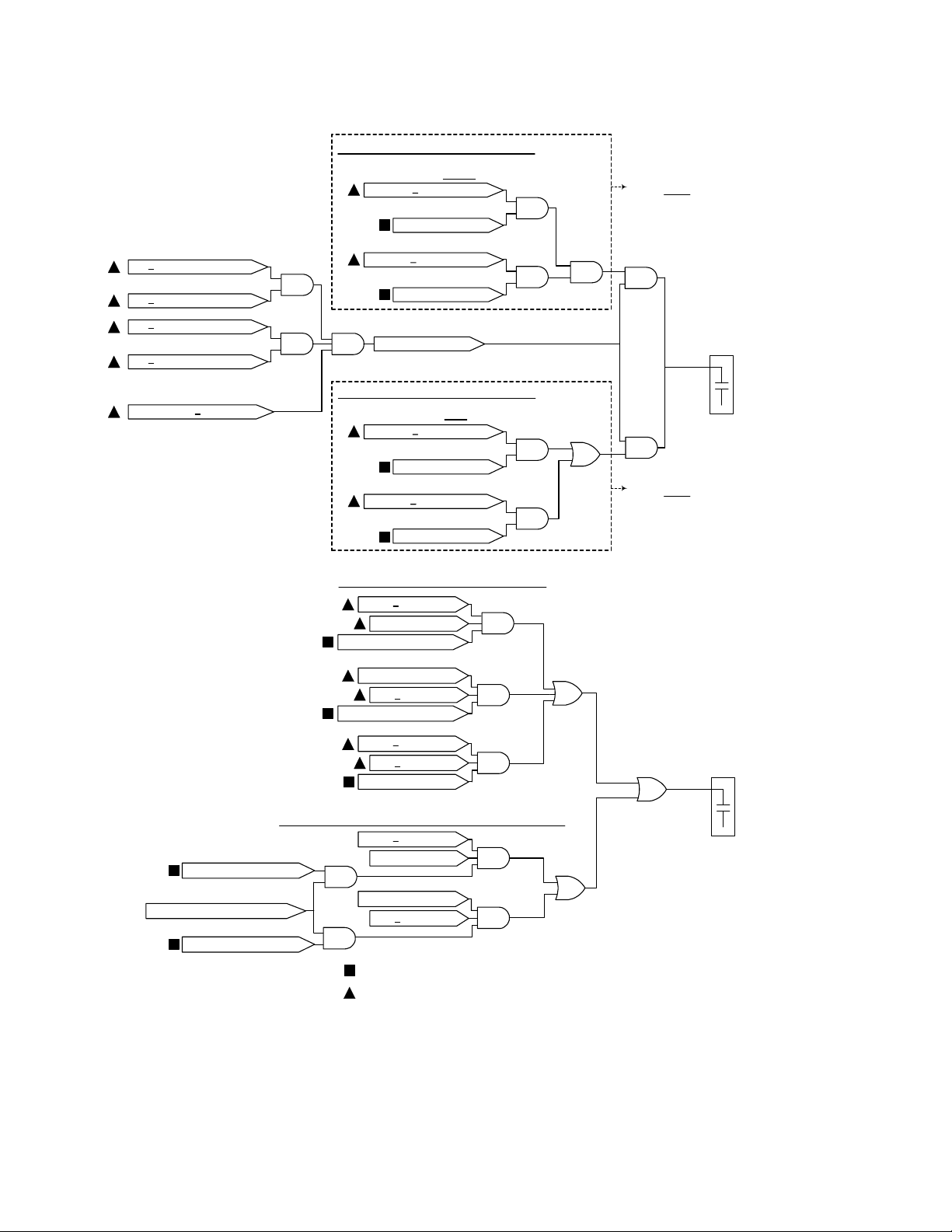
Phase Angle Check Logic
>
V1
Lower Voltage Limit
<
V1
Upper Voltage Limit
>
V
Lower Voltage Limit
X
<
VX Upper Voltage Limit
Phase Angle
<
Phase Limit
Delta V and Delta F Check Logic
AND
AND AND
Delta V and Delta F Check Logic
With Delta V AND Delta F Enabled
|V1- VX| < Delta V Limit
AND
Delta V Is Enabled
|F1- FX| < Delta F Limit
AND
Delta F Is Enabled
Phase Angle OK
With Delta V OR Delta F Enabled
|V1- VX| < Delta V Limit
AND
Delta V Is Enabled
|F1- FX| < Delta F Limit
AND
Delta F Is Enabled
AND
OR
Application – 2
Only one Delta V and
Delta F Check Scheme
may be active at a time.
AND
Sync Check Timer
Output Seal-in Timer
25S
Output
Contact
AND
Only one Delta V and
Delta F Check Scheme
may be active at a time.
Dead V1 Hot VX Enabled
Dead Input Enable
Selected INPUT Is Activated
Dead VX Hot V1 Enabled
Dead Line/ Dead Bus Check Logic
V1
<
Dead Limit
pos
VX > Dead Limit
Dead V1 Hot VX Enabled
V1
Dead Limit
>
pos
VX < Dead Limit
Dead VX Hot V1 Enabled
V1
<
Dead Limit
pos
VX < Dead Limit
Dead V1 VX Enabled
AND
AND
AND
Dead Line/ Dead Bus Check Input Initiate Logic
V1
<
Dead Limit
pos
AND
AND
AND
AND
VX > Dead Limit
V1
Dead Limit>
pos
VX < Dead Limit
User Software Setting
Measured Variable
Figure 2-17 Sync Check Logic Diagrams
OR
OR
Dead Check Timer
Output Seal-in Timer
OR
25D
Output
Contact
2–23
Page 75
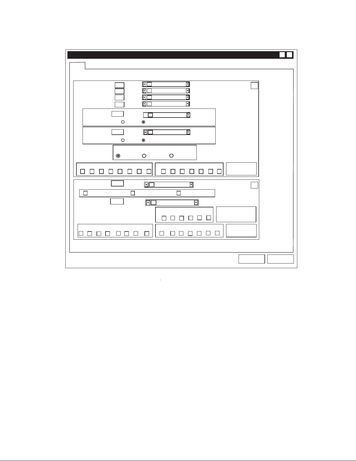
M-3425A Instruction Book
F25
Phase Angle Window:
Upper Voltage Limit:
Lower Voltage Limit:
Sync Check Delay:
Delta Voltage:
Delta Frequency: 0.001 Hz 0.500 Hz
(25) - SYNC CHECK
o
0
60 V
40 V
1 Cycle
1.0 V 50.0 V
Enable Disable
Enable Disable
25S Sync Check Phase
Phase AB Phase BC
Phase CA
o
90
140 V
120 V
8160 Cycles
X?
25S
8765432 1 FL654321
OUTPUTS
Dead Voltage Limit:
Dead V1 Hot VX Hot V1 Dead VX Dead V1 Dead VX
Dead Time Delay:
OUTPUTS
87 65 43 2 1
@
0 V 60 V
1 Cycle 8160 Cycles
Blocking Inputs
Dead Input Enable
654321
Blocking Inputs
FL654321
Expanded I/P Initiate
@ : WARNING, you have not selected an output!
Figure 2-18 Sync Check (25) Setpoint Ranges
Expanded I/Os
Expanded I/Os
Save
25D
Cancel
2–24
Page 76
27 Phase Undervoltage
The Phase Undervoltage function (27) may be used
to detect any condition causing long- or short-term
undervoltage. This is a true three-phase function in
that each phase has an independent timing element.
The ranges and increments are presented in Figure
2-19.
Application – 2
Magnitude measurement depends on the 59/27
Magnitude Select setting. (See Section 2.1,
Configuration, Relay System Setup.) When the RMS
calculation is selected, the magnitude calculation is
accurate over a wide frequency range (10 to 80 Hz)
and the accuracy of the time delay is +20 cycles. If
DFT calculation is selected, the magnitude
calculation is accurate near 50 or 60 Hz, and the
timer accuracy is &1 cycle.
27 #1 PICKUP
________ Volts
27 #1 DELAY
________ Cycles
F27
Pickup:
Delay:
8765432 1 FL6 54321
Pickup:
Delay:
(27) - PHASE UNDERVOLTAGE
1 Cycle
OUTPUTS
1 Cycle
27 #2 and 27 #3 Screens are identical to 27 #1.
5 V
@
5 V
180 V
8160 Cycles
Blocking Inputs
180 V
8160 Cycles
X?
#1
Expanded I/Os
#2
OUTPUTS
8765432 1 FL6 54321
Pickup:
Delay:
OUTPUTS
8765432 1 FL6 54321
5 V
1 Cycle
@ : WARNING,You have not selected an output!
@
@
Blocking Inputs
180 V
8160 Cycles
Blocking Inputs
Figure 2-19 Phase Undervoltage (27) Setpoint Ranges
Expanded I/Os
Expanded I/Os
Save
#3
Cancel
2–25
Page 77
M-3425A Instruction Book
27TN Third Harmonic Undervoltage, Neutral
For ground faults near the stator neutral, the Third
Harmonic (180/150 Hz) Neutral undervoltage
function (27TN) provides stator ground-fault
protection for high-impedance-grounded generator
applications (See Figure 2-20). When used in
conjunction with the fundamental neutral
overvoltage (60/50Hz) function (59N), 100% stator
ground-fault protection can be provided. This is
illustrated in Figure 2-20.
The 27TN function can be supervised by the
positive-sequence undervoltage element.
Undervoltage supervision can prevent tripping when
the generator field is not energized or the unit is
not yet synchronized.
In some generators, the third harmonic voltage
can be very low, especially during light load
conditions. It is also observed in some generator
installations that the third harmonic voltage is
considerably reduced for a specific range of power
output (band). To prevent mis-operation during
these conditions, the 27TN function can be
programmed to be supervised (blocked) by low
forward power, low reverse power, low Vars (lead
and lag), low power factor (lead/lag), and when
the forward power is inside a band.
To properly handle pump storage operations, the
M-3425A forward power blocking algorithm is enable
from “zero per unit” to the forward power setpoint.
During plant startup, after the field is flashed and
27TN #2 Screens are identical to 27TN #1.
before the unit synchronized, small current
measurement errors cause the measured power
to fluctuate (typically <0.2%.) This may result in
a measured power value that is negative (i.e.,
–0.001 pu.) If the reverse power blocking is not
enabled, the 27TN may be momentarily unblocked,
resulting in a relay operation and nuisance generator
trip. It is highly recommended that if the Forward
Power Blocking is used, both the Forward Power
Blocking and Reverse Power Blocking be enabled
and set.
In the majority of the cases, these blocking
functions will be disabled, except for those operating
cases where the third harmonic neutral voltage
magnitude is less than 0.5 V. The settings for
the blocking functions should be set based on
field measurements. Blocking regions are
illustrated in Figure 2-21.
The 27TN setting depends on the actual thirdharmonic neutral voltage level seen during normal
operation of the generator. The setting should
be about 50% of the minimum third-harmonic
voltage observed during various loading conditions.
This can be most conveniently measured during
commissioning of the relay. Since the relay
measures the third harmonic voltage levels and
will display those values directly, no additional
equipment is required. The undervoltage inhibit
setting should be about 80% to 90% of the nominal
voltage. The ranges and increments are presented
in Figure 2-22.
27TN #1 PICKUP
________ Volts
27TN #1 POS SEQ VOLT BLK
disable ENABLE
27TN #1 POS SEQ VOLT BLK
________ Volts
27TN #1 FWD POWER BLK
disable ENABLE
27TN #1 FWD POWER BLK
________ PU
2–26
Relay volts are equal to the primary neutral voltage divided by the
grounding transformer ratio. Generally set for approximately 50%
of the minimum third harmonic voltage observed during various loading
conditions.
27TH #1 REV POWER BLK
disable ENABLE
27TN #1 REV POWER BLK
________ PU
27TN #1 LEAD VAR BLK
disable ENABLE
27TN #1 LEAD VAR BLK
________ PU
Page 78
Application – 2
27TN #1 LAG VAR BLK
disable ENABLE
27TN #1 LAG VAR BLK
________ PU
27TN #1 LEAD PF BLK
disable enable
27TN #1 LEAD PF BLK
________ LEAD
27TN #1 LAG PF BLK
disable enable
27TN #1 LAG PF BLK
________ LAG
27TN #1 BAND FWD PWR BLK
disable enable
27TN#1 LO B FWD PWR BLK
________ PU
27TN#1 HI B FWD PWR BLK
________ PU
27TN #1 DELAY
________ Cycles
Fundamental (60/50 Hz) neutral
voltage during ground fault
Third Harmonic (180/150 Hz) neutral
voltage during ground fault
Neutral Voltage
27TN Setpoint
59N Setpoint (typically 5V)
Pre-fault third harmonic voltage level
Pre-fault fundamental neutral voltage level
Neutral End of
Generator
0%
50%
100%
Fault Position
(% of stator winding measured
27TN
from neutral end of generator)
Protection
provided by:
5% - 10%
59N
0-30%
Figure 2-20 Third Harmonic Undervoltage (27TN) Protection Characteristics
Terminal End
of Generator
2–27
Page 79
M-3425A Instruction Book
Lag var Block
-P
Reverse
Power
Block
Lead var Block
+Q
Block Block
Low Band Forward
Power Block
Forward
Power
Block
-Q
Figure 2-21 27TN Blocking Regions
+P
High Band
Forward
Power Block
2–28
Page 80
#2
#1
(27TN) - THIRD HARMONIC UNDERVOLTAGE, NEUTRAL
Pickup:
Pos. Seq. Voltage Block:
Forward Power Block:
Reverse Power Block:
Lead var Block:
Lag var Block:
Lead Power Factor Block:
Lag Power Factor Block:
Hi Band Forward Power Block:
Lo Band Forward Power Block:
Delay:
OUTPUTS
8765432 1
0.1 V
5 V
0.01 PU
-1.00 PU
-1.00 PU
0.01 PU
0.01 Lead
0.01 Lag
0.01 PU
0.01 PU
1 Cycle
@
14.00 V
180 V
1.00 PU
-0.01 PU
-0.01 PU
1.00 PU
1.00 Lead
1.00 Lag
1.00 PU
1.00 PU
8160 Cycles
Blocking Inputs
FL 6 5 4 3 2 1
Enable Disable
Enable Disable
Enable Disable
Enable Disable
Enable Disable
Enable Disable
Enable Disable
Enable Disable
Expanded I/O’s
Application – 2
#
1
@ : WARNING, You have not selected an output!
Save
Cancel
Figure 2-22 Third Harmonic Undervoltage, Neutral Circuit (27TN) Setpoint Ranges
2–29
Page 81

M-3425A Instruction Book
32 Directional Power
The Directional Power function (32) can provide
protection against both generator motoring and
overload. It provides three power setpoints, each
with a magnitude setting and a time delay. The
Forward Power direction (power flow to system) is
automatically chosen when the pickup setting is
positive and the Reverse Power direction (power
flow to generator) is automatically chosen when the
pickup setting is negative. The range, as shown is
from –3.000 PU to 3.000 PU where 1.0 PU is equal
to the generator MVA rating. Normalized PU power
flow measurements are based on Nominal Voltage
and Nominal Current setting, as shown in Section
2.1, Configuration, Relay System Setup.
Protection from Generator Motoring
Protection against motoring is provided by selecting
a negative pickup with Over/Under power set to
Over. The relay will operate when the measured
real power is greater (more negative) than the pickup
setting in the reverse direction.
In some steam generator applications it is desirable
to trip the generator when the forward power is less
than a small value. This is due to the fact that the
trapped steam will cause the generator to supply a
small amount of power even though the steam
valves are closed. In this case the Over/Under
power setting is set to Under and a positive pickup
setting is chosen. The relay will trip when the
measured forward power is less than the pickup
value. The function should be blocked when the
generator breaker is open (using contact input
blocking) otherwise the function will trip and prevent
the generator from being brought online.
Protection from Generator Overload
Protection from generator overload is provided by
selecting a positive pickup setting with Over/Under
Power setting set to Over. The relay will operate
when the measured real power is greater than the
pickup setting.
Protection from Excessive Reactive Power
The directional power element #3 can be set to
operate on either real power or reactive power.
When protection from excessive reactive power is
required the element #3 can be set to operate on
reactive power. The relay will operate when the
measured reactive power exceeds the pickup
setting.
Figures 2-23 through 2-26 show reverse power, low
forward power, over power, and over reactive power
applications.
32 #1 PICKUP
________ PU
32 #1 DELAY
________ Cycles
32 #1 TARGET LED
disable enable
32#1 UNDER/OVER POWER
over under
32 #2 PICKUP
________ PU
32 #2 DELAY
________ Cycles
The reverse power pickup setting should be based on the type of
prime mover and the losses when the generator is motoring.
Reverse power relays should always be applied with a time delay in
order to prevent mis-operation during power swing conditions. Typical
time delay settings are 20 to 30 seconds.
Target LED for the 32 Function elements can be individually enabled
or disabled.
When Low Forward Power protection is desired, set this to Under
with a positive pickup setting. The relay will trip when the real power
measurement is
less than or equal to
the pickup setpoint.
If used, positive direction power settings can be used for overload
protection, providing either alarm or tripping or both, when power
equals or exceeds the setting. The pickup and time delay settings
should be based on the capability limit of the generator.
A second reverse power setting can be used for sequential tripping
of the generator in which case the associated time delay will be in
the range of 2 to 3 seconds.
2–30
Page 82
32 #2 TARGET LED
disable enable
32#2 UNDER/OVER POWER
over under
32 #3 PICKUP
________ PU
32 #3 DELAY
________ Cycles
32 #3 TARGET LED
disable enable
32#3 UNDER/OVER POWER
over under
Application – 2
32 #3 DIR POWER SENSING
real reactive
Reverse
Power Flow
-1.0 PU
TRIP
Pickup
Directional Power Sensing for Element #3 can be selected as Real or Reactive.
Forward
Power Flow
PU
1.0 PU
Figure 2-23 Tripping on Reverse Power Flow (Over Power with Negative Pickup)
2–31
Page 83

M-3425A Instruction Book
Reverse
Power Flow
-1.0 PU
1.0 PU
Forward
Power Flow
TRIP
Pickup
Figure 2-24 Tripping on Low Forward Power (Under Power with Positive Pickup)
PU
2–32
Reverse
Power Flow
-1.0 PU
Pickup
Figure 2-25 Tripping on Overpower (Over Power with Positive Pickup)
1.0 PU
Forward
Power Flow
PU
TRIP
Page 84
Pickup
Application – 2
Reactive Power
Into System
TRIP
Reverse
Power Flow
Forward
Power Flow
PU
-1.0 PU
1.0 PU
Reactive Power
Into Generator
Figure 2-26 Tripping on Over Reactive Power with Element #3 (Over Power, Positive Pickup and
Directional Power Sensing Set to Reactive)
2–33
Page 85
M-3425A Instruction Book
F32
X?
(32) - DIRECTIONAL POWER
Pickup:
Delay:
Overpower Underpower Target LED Enable
8765432 1 FL654321
Pickup:
Delay:
Overpower Underpower Target LED Enable
8765432 1 FL654321
Pickup:
Delay:
Overpower Underpower Target LED Enable
Directional Power Sensing:
8765432 1 FL654321
-3.000 PU
1 Cycle
Real
@
@
Reactive
@
OUTPUTS
-3.000 PU
1 Cycle
OUTPUTS
-3.000 PU
1 Cycle
OUTPUTS
@ : WARNING, You have not selected an output!
3.000 PU
8160 Cycles
Blocking Inputs
3.000 PU
8160 Cycles
Blocking Inputs
3.000 PU
8160 Cycles
Blocking Inputs
#1
Expanded I/Os
#2
Expanded I/Os
#3
Expanded I/Os
Save
Figure 2-27 Directional Power, 3-Phase (32) Setpoint Ranges
Cancel
2–34
Page 86

40 Loss of Field
The Loss-of-Field function (40) provides protection
for a partial or complete loss of field. A variety of
possible settings make the M-3425A Generator
Protection Relay very flexible when applied to lossof-field protection. Ranges and increments are
presented in Figure 2-30.
The loss-of-field function is implemented with two
offset mho elements, an undervoltage element,
and a directional element. The setting for each mho
element, diameter, offset, and time delay, are
adjusted individually. Each element has two time
delay settings. The second time delay (delay with
VC) is applicable with voltage control, and the timer
only starts if the positive sequence voltage is
below the voltage control setting. The function with
voltage control and without voltage control can be
programmed to send to two different output contacts,
if desired. The delay with voltage control may be
enabled on each element but the voltage level
setting is common. The voltage control allows for
faster tripping when low voltage may be caused by
the VAr intake by the machine with loss of
excitation. A common directional unit is provided to
block the relay operation during slightly underexcited
conditions (since approach #1 with negative offset
is inherently directional, the directional element is
Application – 2
not required). The directional unit’s angle setting
) can be set from 0° to 20°.
(Θ
D
The settings of the offset mho elements should be
such that the relay detects the loss-of-field condition
for any loading while not mis-operating during power
swings and fault conditions. Two approaches are
widely used in the industry, both of which are
supported by the M-3425A relay. Both approaches
require knowledge of the reactances and other
parameters of the generator. They are described in
Figure 2-28, Loss of Field (40) — Protective
Approach I and Figure 2-29, Loss of Field (40) —
Protective Approach II.
Positive sequence impedance measurements are
used for the loss of field functions. All impedance
settings are secondary relay quantities and can be
derived from the following formula:
Z
= Z
SEC
where Z
= primary impedance, RC = current transformer
= secondary reflected impedance, Z
SEC
x (RC ÷ RV)
PRI
PRI
ratio, and RV = voltage transformer ratio.
40 #1 DIAMETER
________ Ohms
40 #1 OFFSET
________ Ohms
40 #1 DELAY
________ Cycles
40VC #1 DELAY WITH VC
________ Cycles
The first approach is shown in Figure 2-28,
Loss of Field (40) — Protective Approach I.
Here, both of the offset mho elements (#1 and
#2) are set with an offset of –X
l
÷2, where X
d
is the (unsaturated) direct axis transient reactance of the generator. The diameter of the smaller
circle (#1) is set at 1.0 pu impedance on the
machine base. This mho element detects lossof-field from full load to about 30% load. A small
time delay provides fast protection.
The diameter of the larger circle (#2) is set equal
to Xd, where Xd is the (unsaturated) direct axis
synchronous reactance of the machine. This mho
element can detect a loss-of-field condition from
almost no load to full load. A time delay of 30 to
60 cycles (#2) should be used in order to prevent
possible incorrect operation on stable swings.
The time delay with voltage control is typically
set shorter than the other time delay.
l
d
2–35
Page 87
M-3425A Instruction Book
40 #2 DIAMETER
________ Ohms
40 #2 OFFSET
________ Ohms
40 #2 DELAY
________ Cycles
40VC #2 DELAY WITH VC
________ Cycles
40 VOLTAGE CONTROL
________ Volts
The second approach is shown in Figure 2-29,
Loss of Field (40) – Protective Approach II. In
this approach, one of the mho elements is set
with an offset of –X
l
÷ 2, a diameter of 1.1 Xd-(X
d
÷ 2), and a time delay of 10 to 30 cycles. The
second element is set to coordinate with the
generator minimum excitation limit and steadystate stability limit.
In order to obtain proper coordination, the offset
of this element must be adjusted to be positive.
Typically, the offset is set equal to the unit
transformer reactance (XT). The diameter is
approximately equal to (1.1 X
+ XT). A time
d
delay of 30 to 60 cycles would prevent misoperation on stable swings.
The following table provides suggested time settings
when time delay with VC is used in addition to
standard time delay.
l
d
40 DIRECTIONAL ELEMENT
________ Degrees
Typical setting is 13° (0.974 power factor). This
setting is common to both element #1 and #2.
Approach #1 can also be used for Zone #1, and
approach #2 for Zone #2, where better coordination
with AVR limiters, machine capability limits, and
steady state stability limits can be obtained.
1enoZ 2enoZ
gnitteSlortnoCegatloVA/N
yaleDselcyC51selcyC006,3
CVhtiwyaleDelbasiDselcyC06
Table 2-3 Voltage Control Time Settings
fo%09ot08
egatloVlanimoN
2–36
Page 88
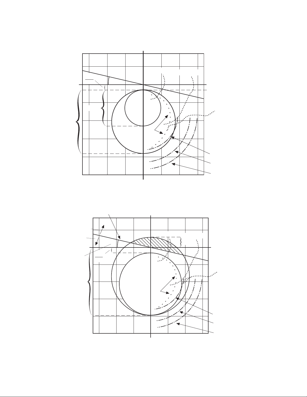
+X
Application – 2
Heavy Load
X'
d
Q
R +R
2
D
Light Load
1.0 pu
X
d
Loss of Excitation
Final Impedance
Locus
X
Figure 2-28 Loss of Field (40)—Protective Approach 1
Directional Element
+X
Underexcited
Steady-State Stability Limit
Machine Capability
Minimum Exciter Limit
Block Direction
Trip Direction
R
Directional
Element Angle
Setting
1.1 X
Heavy Load
Q
D
X'
d
2
d
Loss of Excitation
Final Impedance
Locus
Light Load
X
T
X
Figure 2-29 Loss of Field (40)—Protective Approach 2
+R
Underexcited
Steady-State Stability Limit
Machine Capability
Minimum Exciter Limit
2–37
Page 89
M-3425A Instruction Book
F40
Circle Diameter:
Offset:
Delay:
(40) - LOSS OF FIELD
0.1 Ohm
- 50.0 Ohms
1 Cycle
100.0 Ohms
50.0 Ohms
8160 Cycles
#1
0.1 Ohm
- 50.0 Ohms
1 Cycle
1 Cycle
5 V
0°
@
@
@
@
Blocking Inputs
8160 Cycles
VC Blocking Inputs
100.0 Ohms
50.0 Ohms
8160 Cycles
Blocking Inputs
8160 Cycles
VC Blocking Inputs
180 V
20°
8765432 1 FL654321
Delay with VC:
1 Cycle
VC OUTPUTS
OUTPUTS
8765432 1 FL654321
Circle Diameter:
Offset:
Delay:
OUTPUTS
8765432 1 FL654321
Delay with VC:
VC OUTPUTS
8765432 1 FL654321
Voltage Control:
Directional Element:
@ : WARNING, You have not selected an output!
Expanded I/Os
VC#1
Expanded I/Os
#2
Expanded I/Os
VC#2
Expanded I/Os
Save Cancel
Figure 2-30 Loss-of-Field (40) Setpoint Ranges
■ NOTE: Out of Step Block Enable is not available for this release, and will appear greyed-out in display.
2–38
Page 90
46 Negative Sequence Overcurrent
The Negative Sequence Overcurrent function (46)
provides protection against possible rotor
overheating and damage due to unbalanced faults
or other system conditions which can cause
unbalanced three phase currents in the generator.
Ranges and increments are presented in Figure
2-32.
This function has a definite time element and an
inverse time element. The definite time pickup
value and definite operating time are normally
associated with an alarm function. The inverse
time element is usually associated with a trip
function and has a pickup and an operating time
defined by an (I
Setting and I
)2t = K, where K is the Time Dial
2
is the per unit negative sequence
2
current.
The minimum delay for the inverse time function is
factory set at 12 cycles to avoid nuisance tripping.
A maximum time to trip can be set to reduce the
operating times for modest imbalances. An important
feature that helps protect the generator from damage
due to recurring imbalances is a linear reset
characteristic. When I
decreases below the pickup
2
Application – 2
value, the trip timer takes four minutes to reset
from its 100% trip level. Figure 2-31, Negative
Sequence Overcurrent Inverse Time Curves,
illustrates the inverse time characteristic of the
negative sequence overcurrent function.
Operating times are lower than shown in Figure
2-31 when measured current values are greater
than 15 A (3 A for 1 A rated circuit).
The first task of setting this function is to determine
the capabilities of the associated machine. As
established by ANSI standards, the machine limits
are expressed as (I2)2t = K. The value of K is
established by the machine design and is generally
provided on test sheets of the machine. The relay
can accommodate any generator size because of
the wide range of K settings from 1 to 95. Typical
values can be found in ANSI C50.13-1977.
The negative sequence pickup range is from 3% to
100% of the Nominal Current value input during
system setup (see Section 2.1, Configuration).
This protection must
not
operate for system faults
that will be cleared by system relaying. This requires
consideration of line protection, bus differential and
breaker failure backup protections.
46DT PICKUP
________ %
46DT DELAY
________ Cycles
46IT PICKUP
________ %
46IT MAX DELAY
________ Cycles
46IT RESET TIME
________ Seconds
46IT TIME DIAL
________
The pickup setting is usually quite low (3–5%)
and the output of this function is usually connected to alarm only.
Time delay should be set high enough to avoid
alarms on transients.
The 46 Inverse Time pickup setting should coincide
with the continuous negative sequence current
capability of the generator operating at full output.
The maximum trip time is used to reduce the
longer trip times associated with low to moderate imbalances to a preset time.
The time dial setting corresponds to the K provided
by the generator manufacturer for the specific unit
being protected. See Figure 2-31 for the negative
sequence overcurrent inverse time curves.
2–39
Page 91
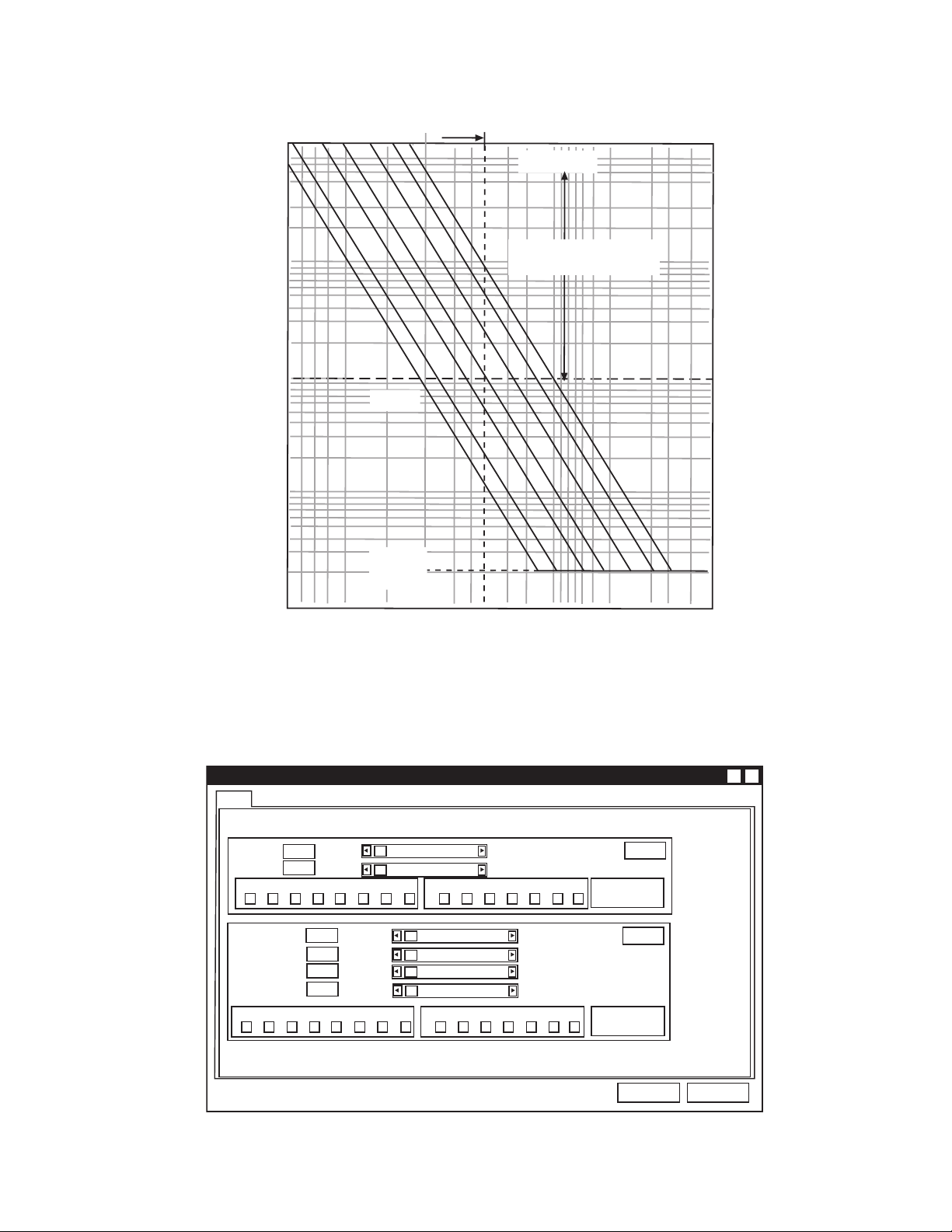
M-3425A Instruction Book
Negative Sequence Current (% of Nominal Value)
Time (Seconds)
Pickup Setting Range
1000
800
600
400
200
100
80
60
40
20
10
8
6
4
2
1
0.6
0.4
0.2
0.1
4 5 6 8 10 20 40 60 80 100 150 200 300 400 500600 800 1000 1000 2000 3000 4000
K
95
To 65,500 cycles
50
25
10
5
2
1
Definite Maximum
Time Setting Range
I
2
2
t=K
Definite
Minimum
Time
*
■■
■ NOTE: When the phase current exceeds 3X I nominal, the operating times will be greater than those
■■
shown.
* 0.24 seconds for 50 Hz units.
2–40
Figure 2-31 Negative Sequence Overcurrent Inverse Time Curves
F46
(46) - NEGATIVE SEQUENCE OVERCURRENT
Pickup:
Delay:
8765432 1 FL654321
Pickup:
Time Dial:
Maximum Time:
Reset Time:
8765432 1 FL654321
Figure 2-32 Negative Sequence Overcurrent (46) Setpoint Ranges
3%
1 Cycle
OUTPUTS
3%
1
600 Cycles
1 Second
OUTPUTS
@ : WARNING, You have not selected an output!
X?
100%
8160 Cycles
@
@
Blocking Inputs
100%
95
65500 Cycles
600 Seconds
Blocking Inputs
Def. Time
Expanded I/Os
Inv. Time
Expanded I/Os
Save
Cancel
Page 92
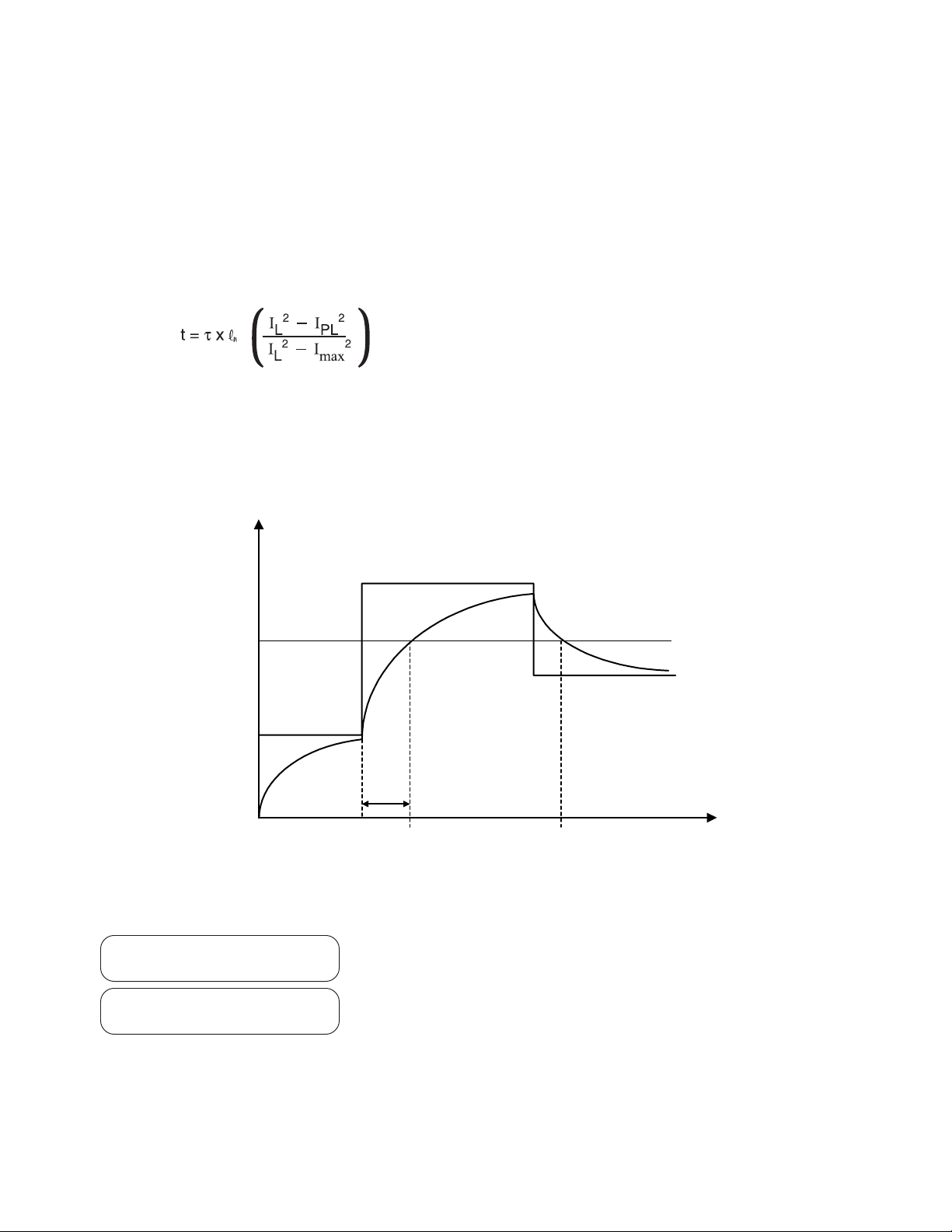
49 Stator Overload Protection
The Stator Thermal Overload function (49) provides
protection against possible damage during overload
conditions. The characteristic curves are based on
IEC-255-8 standard, and represent both cold and
hot curves. The function uses the thermal time
constant of the generator and stator maximum
allowable continuous overload current (I
implementing the inverse time characteristic.
max
) in
Where: t = time to trip
τ = thermal time constant
IL = load current
IPL = pre-load current
I
= maximum allowed continuous overload current
max
Example
: If we consider that the generator was
Application – 2
loaded with 80% of its rating power prior to overload,
then the current goes up to 2.0 times the maximum
current ((I
(see Figure 2-28), we have t/τ =0.1133. If τ =30
)=2.0). Selecting the curve P=0.8
L/Imax
minutes, then the time delay for this condition
would be: t = 0.1133 x 30 = 3.3999 minutes.
The 49 function has two elements, one of which
can be used for trip and the other for alarm.
Current-Square
2
I
max
49 #1 TIME CONSTANT
________ Min
2
I
L
2
I
PL
2
I
L
2
I
PL
t
Tripped
Not Tripped
Figure 2-33 Time Constant, Function 49
Selects the time constant, ‘τ ’
2
I
L
t
49#1 MAX OVERLOAD CURR
________ Amps
Selects the maximum allowed continuous overload
current.
49#2 Screens are identical to those for 49#1.
2–41
Page 93
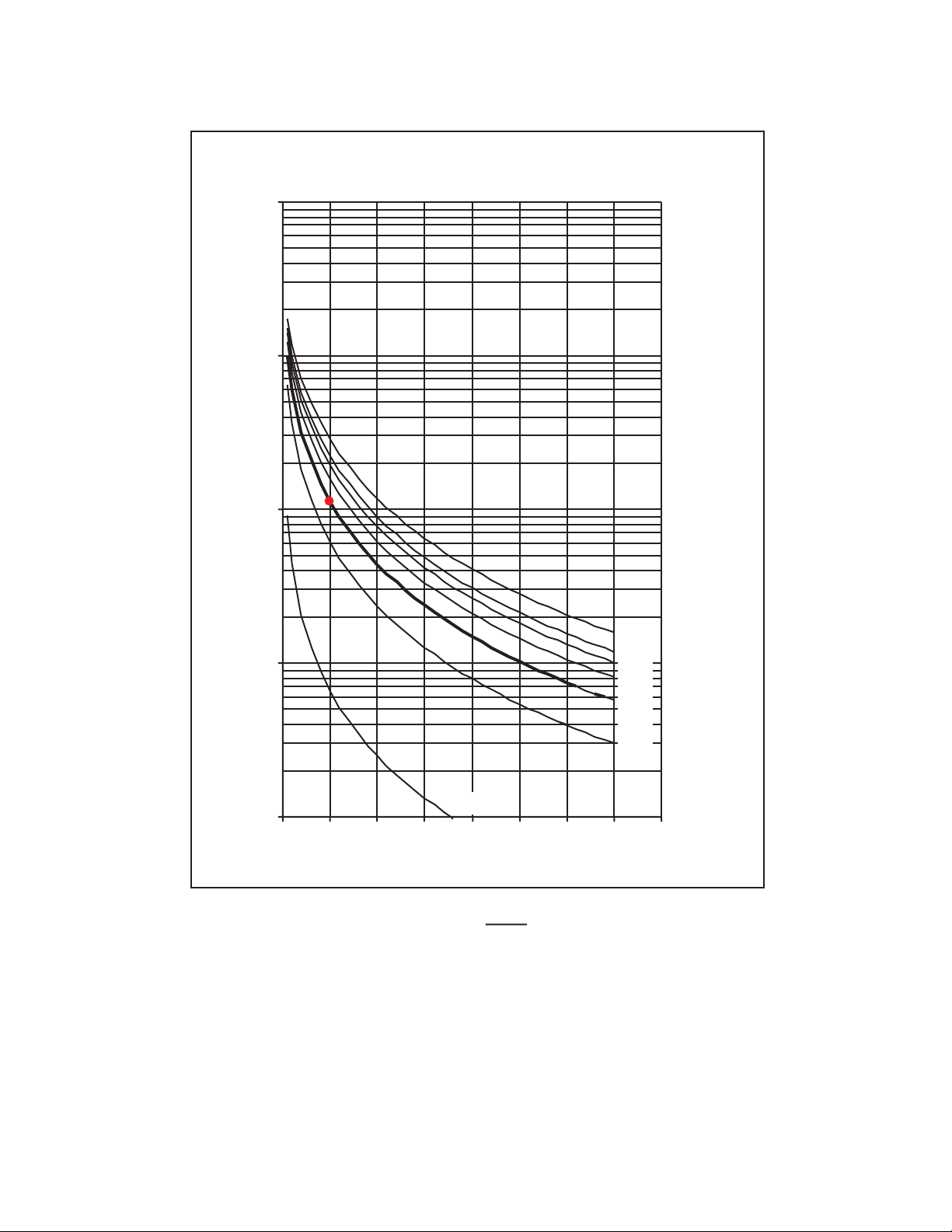
M-3425A Instruction Book
49 - Overload Curves
10
1
t / t
P=0.99
123456789
IL/I
max
I
where: P=
PL
I
max
P=0.0
P=0.5
P=0.6
P=0.7
P=0.8
P=0.9
0.1
0.01
0.001
2–42
Figure 2-34 49 Function Overload Curves
Page 94
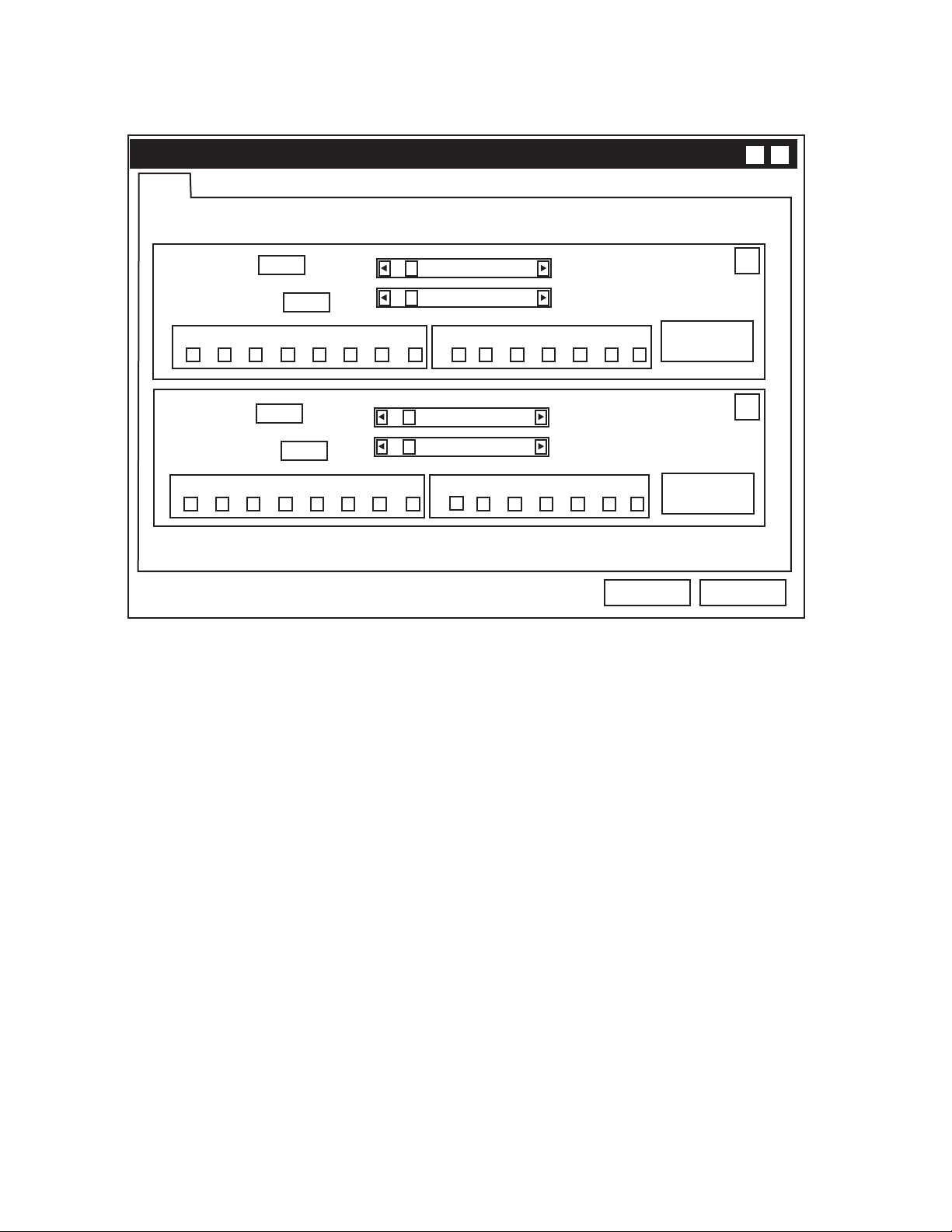
F49
Application – 2
X?
(49) - STATOR OVERLOAD
Time Constant:
Max. Overload Current:
8765432 1
Time Constant:
Max. Overload Current:
8765432 1
@ : WARNING, You have not selected an output!
1.0 min
1.00 A
1.0 min
1.00 A
Figure 2-35 Stator Thermal Protection (49) Setpoint Ranges
999.9 min
10.00 A
@
FL 6 5 4 3 2 1
@
FL654321
Blocking InputsOUTPUTS
999.9 min
10.00 A
Blocking InputsOUTPUTS
#1
Expanded I/Os
#2
Expanded I/Os
Save Cancel
2–43
Page 95
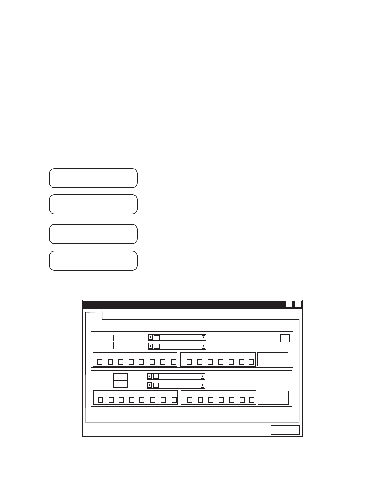
M-3425A Instruction Book
50/50N Instantaneous Overcurrent, Phase and
Neutral Circuits
The Instantaneous Phase (50) and Instantaneous
Neutral (50N) overcurrent functions provide fast
tripping for high fault currents. The settings of both
functions must be set such that they will not pickup
for fault or conditions outside the immediate
protective zone. If the neutral current input is
connected to a step-up transformer’s neutral CT,
the 50N function can be used as a breaker flashover
protection when used in conjunction with external
breaker failure protection. Ranges and Increments
are presented in Figures 2-36 and 2-37. The function
automatically selects fundamental RMS or total
RMS calculation based on the input frequency.
When the generator frequency is within &5 Hz
from the nominal frequency, it uses fundamental
RMS calculation. Outside of this range, it uses
total RMS calculation, which will provide protection
during offline down to a frequency of 8 Hz.
For providing off-line protection, one of the elements
can be supervised by a breaker ‘b’ contact, and the
element blocked when the breaker is closed. This
allows the function to be set sensitively (below full
load current).
50#1 PICKUP
________ Amps
50#1 DELAY
________ Cycles
50N PICKUP
________ Amps
50N DELAY
________ Cycles
F50
Pickup:
8765432 1 FL654321
Delay:
The relay current (I
the appropriate CT ratio. These screens are repeated for 50#2 element.
(50) - INSTANTANEOUS OVERCURRENT
0.1 A
1 Cycle
OUTPUTS
@
) is equal to the primary current (Ip) divided by
R
X?
240.0 A
8160 Cycles
Blocking Inputs
Expanded I/Os
#1
2–44
Pickup:
Delay:
8765432 1 FL654321
0.1 A
1 Cycle
OUTPUTS
@ : WARNING, You have not selected an output!
@
240.0 A
8160 Cycles
Blocking Inputs
Expanded I/Os
Save
Figure 2-36 Instantaneous Overcurrent (50) Setpoint Ranges
#2
Cancel
Page 96
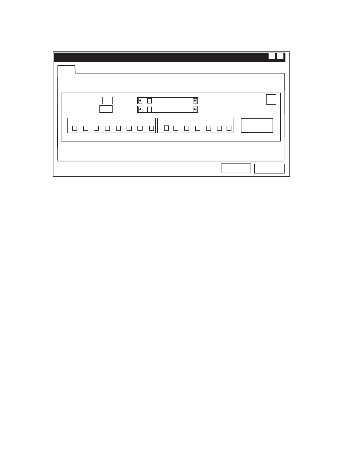
F50N
Application – 2
X?
(50N) - INSTANTANEOUS NEUTRAL OVERCURRENT
Pickup:
Delay:
8765432 1
@ : WARNING, You have not selected an output!
0.1 A
1 Cycle
@
Blocking InputsOUTPUTS
FL 6 5 4 3 2 1
240.0 A
8160 Cycles
Expanded I/Os
Save
Figure 2-37 Instantaneous Neutral Overcurrent (50N) Setpoint Ranges
#1
Cancel
2–45
Page 97

M-3425A Instruction Book
50BF Generator Breaker Failure/HV Breaker
Flashover
The Generator Breaker Failure/HV Breaker Flashover
function (50BF) is applicable when a generator
breaker is present and line side generator CTs are
being used. The 50BF-Ph phase detector element
(if enabled) is used for breaker failure and the
50BF-N (if enabled) provides breaker flashover
protection by providing an additional breaker failure
initiate which is only active when the breaker is
open. For high impedance grounded applications,
the 50BF-N function is inapplicable and must be
disabled. Ranges and increments are presented in
Figure 2-39.
50BF-Ph Generator Breaker Failure: When the
M-3425A Generator Protection Relay detects an
internal fault or an abnormal operating condition, it
closes an output contact to trip the generator breaker
or the unit HV breaker. When a generator breaker is
used, protection is available for the instance where
it fails to clear the fault or abnormal condition. Such
generator breaker failure protection output contacts
must be connected to trip the additional necessary
breakers to isolate the generator from the system.
The breaker-failure condition is usually detected by
the continued presence of current in any one or
more of the phases after a trip has been sent to the
breaker. However, the current detector (50BF-Ph)
may not always give the correct status of the
breaker, especially for generator breakers. This is
because faults and abnormal operating conditions
such as ground faults, overexcitation, over/under
frequency, and reverse power may not produce
enough current to operate the current detectors. For
this reason, the breaker status input 52b contact
must be used, in addition to the 50BF-Ph, to provide
adequate breaker status indication.
Implementation of the generator breaker failure
function is illustrated in Figure 2-38. The breaker
failure timer will be started whenever any one of the
designated output contacts or the external
programmed breaker failure initiate status input are
operated. The timer continues to time if any one of
the phase currents are above the 50BF-Ph pickup
setting or if the 52b contact indicates the breaker is
still closed; otherwise, the timer is reset.
Since current in the generator high side CT which
energizes the 50BF protection (I
, IB, IC) might not
A
extinguish concurrently with the breaker opening for
faults between the CT location and the generator
breaker, a possible area of mis-operation exists.
Usually the risk of faults in this limited area is small
enough to be ignored but should be considered.
50BF-Neutral Element: This instantaneous
overcurrent relay is energized from the generator
neutral CT (See Figure 2-5, One-Line Functional
Diagram). This function is internally in series with a
breaker “b” contact (IN1) to provide logic for the
breaker flashover protection (see Figure 2-38).
HV Breaker Failure (limited) The breaker failure
function may be used for a unit breaker rather than
a generator breaker. It is limited in that it has no
fault detector associated with the unit breaker. Output
contact operation would occur if any of the initiate
contacts close and the 52b contact indicated a
closed breaker after the set time delay.
This operation is chosen by disabling the neutral
element, disabling the phase element, and
designating initiating inputs and outputs and a time
delay setting.
2–46
Page 98
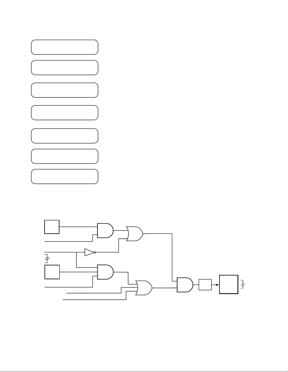
Application – 2
50BF PHASE ELEMENT
disable enable
50BF PICKUP PHASE
________ Amps
50BF NEUTRAL ELEMENT
disable enable
50BF PICKUP NEUTRAL
________ Amps
50BF INPUT INITIATE
i6 i5 i4 i3 i2 i1
50BF OUTPUT INITIATE
o8 o7 o6 o5 o4 o3 o2 o1
50BF DELAY
________ Cycles
If generator breaker failure function is used in this application, ENABLE
here.
Set phase pickup amps.
If the breaker flashover protection is to be used with the generator
breaker failure function of the relay, set ENABLE (enable phase
element also for this application.)
Set the neutral pickup amps.
Designate the status inputs which will initiate the breaker failure
timer. Inputs IN7–IN14 must be set using IPScom®.
Designate the outputs that will initiate the breaker failure timer. Outputs
OUT9–OUT23 must be set using IPScom.
For generator breaker failure protection, the time delay should be set to
allow for breaker operating time plus margin.
50BF-Ph
Overcurrent
I>P.U.
Phase Initiate Enable
IN1 (52b)
Logic high
when breaker open
50BF-N
Overcurrent
I>P.U.
Neutral Initiate Enable
Output Initiate
Input Initiate
AND
NOT
Logic high when breaker closed
OR
AND
OR
Figure 2-38 Breaker Failure Logic Diagram
AND
DELAY
TIME
Programmed
Output
Contacts
2–47
Page 99
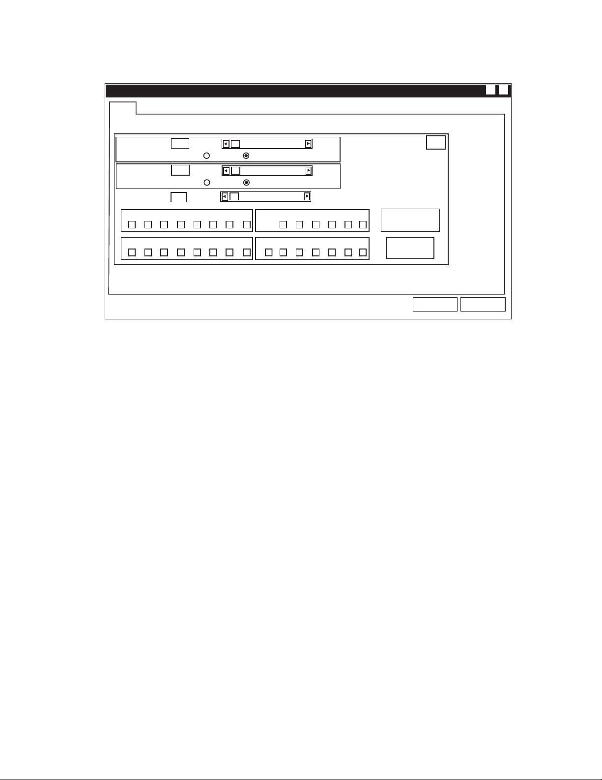
M-3425A Instruction Book
F50BF
X?
(50BF) - BREAKER FAILURE
Phase Current:
Neutral Current:
Delay:
8765432 1
8765432 1
0.10 A
Enable Disable
0.10 A
Enable Disable
1 Cycle 8160 Cycles
@
@ : WARNING, You have not selected an output!
Figure 2-39 Breaker Failure (50BF) Setpoint Ranges
10.00 A
10.00 A
Input InitiateOutput Initiate
654321
Blocking InputsOUTPUTS
FL 6 5 4 3 2 1
50BF
Expanded I/O Initiate
Expanded I/Os
Save
Cancel
2–48
Page 100
50DT Definite Time Overcurrent (for split-phase
differential)
The Definite Time Overcurrent (50DT) function can
be applied in two different configurations based on
the CT connections. When CT configuration shown
in Figure 2-5, One Line Functional Diagram is used,
the 50DT function is used as a definite time phase
overcurrent function to provide protection for external
and internal faults in the generator. When the CTs
are connected to measure the split phase differential
current (shown in Figure 2-6, Alternative One Line
Functional Diagram), the 50DT function can be
used as a split-phase differential relay.
50DT #1 PICKUP PHASE A
________ Amps
50DT #1 PICKUP PHASE B
________ Amps
Application – 2
■ NOTE: When 50DT function is used for split-
phase differential, 50BF, 87 and 87GD
functions must be disabled.
Refer to Section 2.1, Configuration, Relay System
Setup for a description of the 50DT Split-Phase
Operate setting, and Section 2.2, System Diagrams.
In some cases, the generators may be run with a
faulted turn shorted until the generator winding is
repaired. To prevent mis-operation under these
conditions, the pickup setting of the faulted phase
should be set higher than the other phases. To
accommodate this function, individual pickup
settings are available for each phase. Ranges and
increments are presented in Figure 2-40
50DT #1 PICKUP PHASE C
________ Amps
50DT #1 DELAY
________ Cycles
F50DT
(50DT) - DEFINITE TIME OVERCURRENT
Pickup (A):
Pickup (B):
Pickup (C):
Delay:
OUTPUTS
8765432 1 FL654321
Pickup (A):
Pickup (B):
Pickup (C):
Delay:
OUTPUTS
8765432 1 FL654321
50DT #2 screens are identical to 50DT #1.
0.20 A
0.20 A
0.20 A
1 Cycle
@
0.20 A
0.20 A
0.20 A
1 Cycle
@
240.0 A
240.0 A
240.0 A
8160 Cycles
Blocking Inputs
240.0 A
240.0 A
240.0 A
8160 Cycles
Blocking Inputs
X?
#1
Expanded I/Os
#2
Expanded I/Os
@ : WARNING, You have not selected an output!
Save Cancel
Figure 2-40 Definite Time Overcurrent (50DT) Setpoint Ranges
2–49
 Loading...