

Page 1
Instruction Book
M-2601/02/03 Autodaptive
Regulator Control
®
Page 2
CONTROLS
Autodaptive
®
Regulator Control
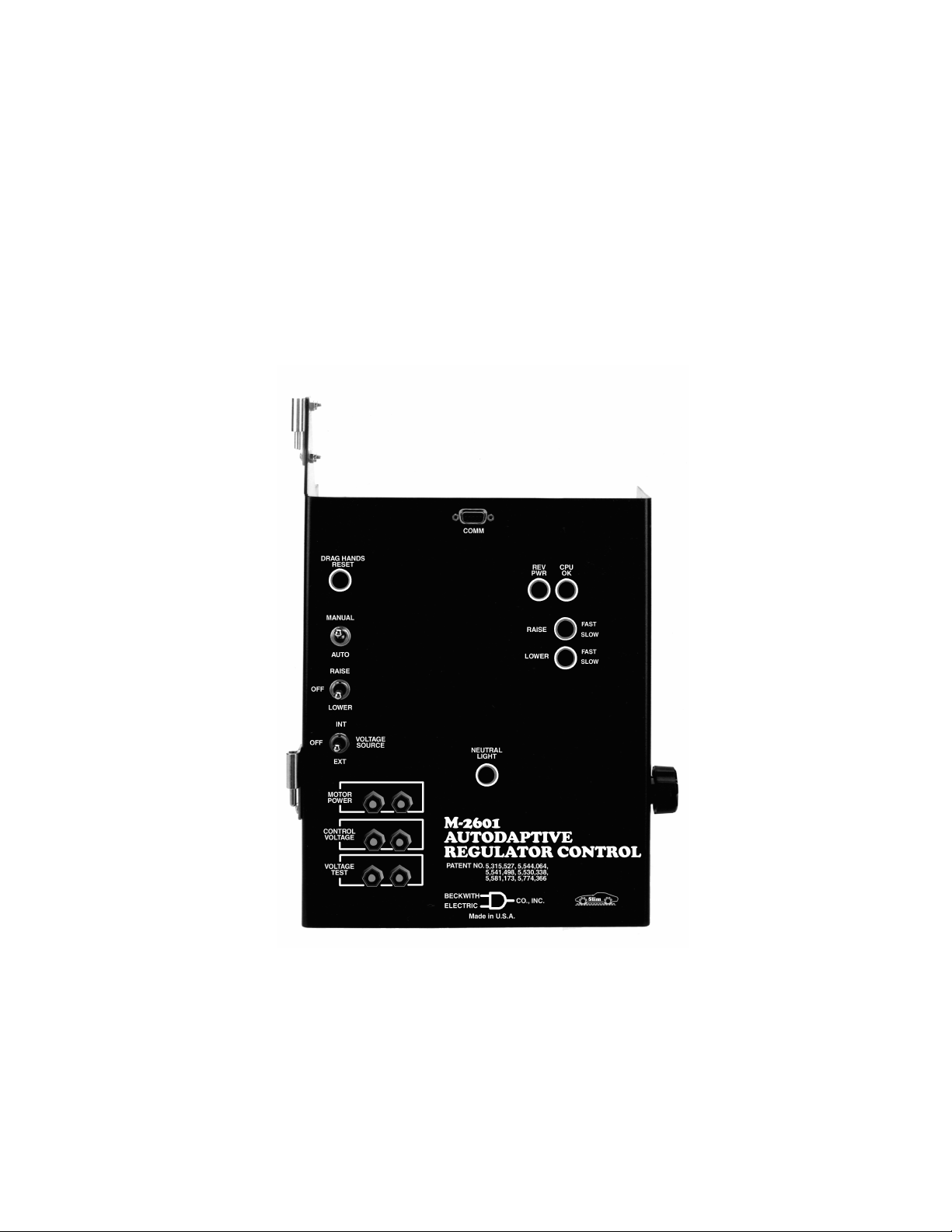
M-2601
Replaces Siemens Regulators MJ-1A, MJ-2A, MJ-3, MJ-3A,
MJ-X; IJ-2, IJ-2A; SJ-4, SJ-5, SJ-6; UJ-2, UJ-4, UJ-5, UJ-5C
and some UA Series Regulator Controls
• Adaptive control feature significantly reduces number of tap
changes for a given Voltage Regulation Quality Factor (VRQF)
• Uses proprietary sampling to measure fundamental voltage, Watts
and VArs at a rate of 240 samples per half cycle
®
• Enhanced data output display with SLIMcom
software
Page 3

M-2601 Autodaptive Regulator Control
The M-2601 Autodaptive® Regulator Control is a unique microcontroller-based solution to regulator control
requirements. Using conventional Siemens Regulator inputs, the control accomplishes regulator control,
based on voltage. Communication and control features of the M-2601 are accomplished utilizing either
M-2802 SLIMcom® for Windows™ from a PC platform, or M-2808 SLIMcom for Visor™ Communications
Software.
Features
The M-2601 Autodaptive Regulator Control includes a user-defined Bandcenter and Voltage Regulation
Quality Factor (VRQF) that permits optimization of the tapchanging process. Also included are: a DRAG
HANDS RESET button, a VOLTAGE SOURCE selector switch and binding posts for Motor Power, Control
Voltage and Voltage Test. Separate fuses for motor power, control, relays and the neutral circuit are located
on the rear of the panel.
Configurable setpoints include:
Bandcenter: Adjustable from 90.0 V to 135.0 V in 0.1 V increments.
Bandwidth: 1 V, predetermined by regulator step size.
VRQF: Adjustable from 0.4 V to 2.0 V in 0.1 V increments.
CT to VT Phasing Correction: Adjustable from 0° to +330° in 30° increments.
VT User Correction Voltage: VT correction from –12 V to +12 V in 0.01 V increments.
CT User Correction Multiplier: Adjustable from 50% to 200%, in 1% increments.
Voltage Limiting: Upper Voltage Limit adjustable from 90 V to 136 V, Lower Voltage Limit adjustable from
89 V to 135 V.
Line Drop Compensation: R & X (forward and reverse) adjustable from –24 V to +24 V in 1 V increments.
Intertap Minimum Delay: Adjustable from 5 seconds to 15 seconds in 0.1 second increments.
Raise/Lower Maximum Output Hold Time: Adjustable from 1 second to 15 seconds in 0.1 second
increments.
VAr Bias Setpoints:
Largest Cap Bank
: Adjustable from 0 KVAr to 11057 KVAr.
Control Functions
Presettable Operations Counter: This software counter increments by one or two counts (user-selectable)
per close/open cam switch operation, and may be preset by the user from 0 to 999,999.
Resettable Operations Counter: A second software counter, similar to the operations counter, which may
be reset by the user.
Inputs
Control Voltage Input: Nominal 120 V ac, 60 Hz; operates properly from 80 V ac to 140 V ac. The burden
imposed on the input is 6 VA or less.
Motor Power Input: Nominal 120 V ac or 240 V ac, 60 Hz, at up to 6 A.
Line Current Input: Line drop compensation is provided by a current transformer input with a 0.2 A full scale
rating. The burden imposed on the current source is 0.03 VA or less, at 200 mA. The input will withstand 400
mA for two hours and 4 A for 1 second.
The unit will withstand twice the voltage input for one second, and four times the voltage input for one cycle.
Fuse protected for voltage above these limits.
–2–
Page 4

M-2601 Autodaptive Regulator Control
Front Panel Controls
AUTO/MANUAL switch: Selects operational mode of regulator.
RAISE/OFF/LOWER switch: Provides manual tap position control.
VOLTAGE SOURCE: Allows the selection of either an internal or external voltage source.
LED Indicators
The front panel LED indicators alert the user to the following conditions:
Out-of-Band RAISE and LOWER (3 position): GREEN (Initial Timing), AMBER (switch operation in 1 to 5
minutes), RED (switch operation in 1 minute or less).
CPU OK, flashing GREEN, indicates the control is working properly.
REV PWR, RED, indicates a reverse power condition exists.
NEUTRAL LIGHT, AMBER, indicates regulator is in the neutral position.
Output Contacts
Raise Output: Capable of switching 6 A at 120 V ac to 240 V ac motor power.
Lower Output: Capable of switching 6 A at 120 V ac or 240 V ac motor power.
Voltage Measurement Accuracy
Voltage accuracy of K0.7% in accordance with ANSI/IEEE C57.15-1986 defining control accuracy of
operation.
Communications
Serial communications is available via a front panel-mounted, optically-isolated RS-232 serial data port in a
DE 9-pin configuration, with available data rate of 9600 baud.
Environmental
Temperature: Stated accuracies maintained from –40°C to +80°C.
Humidity: Stated accuracies are maintained up to 95% relative humidity (non-condensing).
Fungal Resistance: A conformal coating is used on the printed circuit board to inhibit fungal growth.
Transient Protection
High Voltage: All input and output terminals will withstand 1500 V ac to chassis or instrument ground for one
minute, for all terminals to ground with a leakage current less than 25 mA. Input and output circuits are
electrically isolated from each other, from other circuits and from ground.
Surge Withstand Capability: All input and output circuits are protected against system transients. Units
pass all requirements of ANSI/IEEE C.37.90.1-1989 defining surge withstand capability.
Radiated Electromagnetic Withstand Capability: All units are protected against electromagnetic radiated
interference from portable communications transceivers.
Electrostatic Discharge Sensitivity: Per IEC 1000–4.
Physical
Size: 15" high x 9-7/8" wide x 3-1/2" deep (38.1 cm x 25.08 cm x 8.9 cm)
Mounting: Mechanically interchangeable with existing Siemens equipment.
Approximate Weight: 4 lbs, 13 oz (2.18 kg)
Approximate Shipping Weight: 10 lbs (4.54 kg)
–3–
Page 5

Accessories
M-2802 SLIMcom® for Windows
M-2808 SLIMcom for Visor
Metering
The following are examples of measured and calculated parameters that are available in real-time:
• PrimaryVoltage • Primary Current • Power Factor
• KWatts** • KVArs** • KVA**
• Secondary Voltage • Secondary Current • VRQF
• CT Phasing • Avg Taps/Day • Tap Position
• Preset Counter • Alarm Status • Voltage Profile
Historical Data Plot
• Up to seven time-stamped analog calculated or measured values
• 1 digital parameter can be plotted
■ NOTE: All stored data available with time stamp. Five minute averaged samples are stored 111 days.
Sampling rate adjustable from 5 to 60 minutes, with resultant change to storage period.
Voltage Outage Plot
• Voltage plots (previous 10 seconds of data) for the last 4 voltage outage events are displayed.
Tap Statistics Plot
• The Tap Statistics Plot presents a graphical representation of tap position usage history.
™
™
✝
Other
• Prints detailed reports of all setpoints and data.
• Entry and Readout of setpoints.
**Value calculated in SLIMcom. All primary quantities are also calculated in SLIMcom.
✝
VRQF is the RMS deviation in the fundamental component of an AC voltage from a desired AC voltage. It is computed as the
square root of the sum of the squares of deviations in the fundamental component of the voltage from the desired value. The
sum is computed as a running recursive average of frequently taken samples of the fundamental component, obtained in at
least one full cycle of the wave. The time constant of the recursive computation is 6 hours. The recursive average takes at
least six hours to settle to a proper sum, and is generally never stopped, once started.
M-2931 Handspring™ Visor™ Deluxe, with SLIMcom for Visor Communications Software
Patents
The M-2601 Autodaptive® Regulator Control is covered by U.S. Patents, 5,315,527, 5,554,064, 5,541,498
and 5,530,338 with other patents pending.
Warranty
The M-2601 Autodaptive Regulator Control is covered by a two year warranty from date of shipment.
Specification subject to change without notice.
BECKWITH ELECTRIC CO., INC.
6190 - 118th Avenue North • Largo, Florida 33773–3724 U.S.A.
Phone (727) 544-2326 • FAX (727) 546-0121
E-MAIL [email protected]
WEB PAGE www.beckwithelectric.com
© 2000 Beckwith Electric Co.
Printed in U.S.A.
800-2601-SP-03 09/01
Page 6
CONTROLS
Autodaptive
®
Regulator Control
M-2602
Replaces General Electric ML-32 and VR-1 Regulators, and
SM-1, SM-2, and SM-2A Regulator Controls
• Adaptive control feature significantly reduces number of tap
changes for a given Voltage Regulation Quality Factor (VRQF)
• Uses proprietary sampling to measure fundamental voltage, Watts
and VArs at a rate of 240 samples per half cycle
®
• Enhanced data output display with SLIMcom
software
Page 7

M-2602 Autodaptive Regulator Control
The M-2602 Autodaptive® Regulator Control is a unique microcontroller-based solution to regulator control
requirements. Using conventional GE Regulator inputs, the control accomplishes regulator control, based on
voltage. Communication and control features of the M-2602 are accomplished utilizing either M-2802
SLIMcom® for Windows™ from a PC platform, or M-2808 SLIMcom for Visor™ Communications Software.
Features
The M-2602 Autodaptive Regulator Control includes a user-defined Bandcenter and Voltage Regulation
Quality Factor (VRQF) that permits optimization of the tapchanging process. Also included are: a DRAG
HANDS RESET button, a VOLTAGE SOURCE selector switch and binding posts for Motor Power, Control
Voltage and Voltage Test. Separate fuses for motor power, control, relays and the neutral circuit are located
on the rear of the panel.
Configurable setpoints include:
Bandcenter: Adjustable from 90.0 V to 135.0 V in 0.1 V increments.
Bandwidth: 1 V, predetermined by regulator step size.
VRQF: Adjustable from 0.4 V to 2.0 V in 0.1 V increments.
CT to VT Phasing Correction: Adjustable from 0° to +330° in 30° increments.
VT User Correction Voltage: VT correction from –12 V to +12 V in 0.01 V increments.
CT User Correction Multiplier: Adjustable from 50% to 200%, in 1% increments.
Voltage Limiting: Upper Voltage Limit adjustable from 90 V to 136 V, Lower Voltage Limit adjustable from
89 V to 135 V.
Line Drop Compensation: R & X (forward and reverse) adjustable from –24 V to +24 V in 1 V increments.
Intertap Minimum Delay: Adjustable from 5 seconds to 15 seconds in 0.1 second increments.
Raise/Lower Maximum Output Hold Time: Adjustable from 1 second to 15 seconds in 0.1 second
increments.
VAr Bias Setpoints:
Largest Cap Bank
: Adjustable from 0 KVAr to 11057 KVAr.
Control Functions
Presettable Operations Counter: This software counter increments by one or two counts (user-selectable)
per close/open cam switch operation, and may be preset by the user from 0 to 999,999.
Resettable Operations Counter: A second software counter, similar to the operations counter, which may
be reset by the user.
Inputs
Control Voltage Input: Nominal 120 V ac, 60 Hz; operates properly from 80 V ac to 140 V ac. The burden
imposed on the input is 6 VA or less.
Motor Power Input: Nominal 120 V ac or 240 V ac, 60 Hz, at up to 6 A.
Line Current Input: Line drop compensation is provided by a current transformer input with a 0.2 A full scale
rating. The burden imposed on the current source is 0.03 VA or less, at 200 mA. The input will withstand 400
mA for two hours and 4 A for 1 second.
The unit will withstand twice the voltage input for one second, and four times the voltage input for one cycle.
Fuse protected for voltage above these limits.
–2–
Page 8

M-2602 Autodaptive Regulator Control
Front Panel Controls
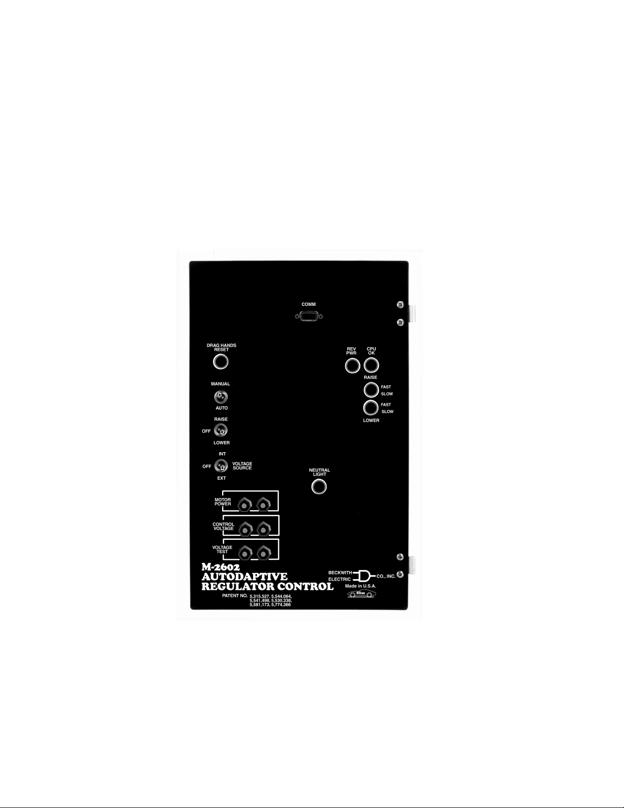
AUTO/MANUAL switch: Selects operational mode of regulator.
RAISE/OFF/LOWER switch: Provides manual tap position control.
VOLTAGE SOURCE: Allows the selection of either an internal or external voltage source.
LED Indicators
The front panel LED indicators alert the user to the following conditions:
Out-of-Band RAISE and LOWER (3 position): GREEN (Initial Timing), AMBER (switch operation in 1 to 5
minutes), RED (switch operation in 1 minute or less).
CPU OK, flashing GREEN, indicates the control is working properly.
REV PWR, RED, indicates a reverse power condition exists.
NEUTRAL LIGHT, AMBER, indicates regulator is in the neutral position.
Output Contacts
Raise Output: Capable of switching 6 A at 120 V ac to 240 V ac motor power.
Lower Output: Capable of switching 6 A at 120 V ac or 240 V ac motor power.
Voltage Measurement Accuracy
Voltage accuracy of K0.7% in accordance with ANSI/IEEE C57.15-1986 defining control accuracy of
operation.
Communications
Serial communications is available via a front panel-mounted, optically-isolated RS-232 serial data port in a
DE 9-pin configuration, with available data rate of 9600 baud.
Environmental
Temperature: Stated accuracies maintained from –40°C to +80°C.
Humidity: Stated accuracies are maintained up to 95% relative humidity (non-condensing).
Fungal Resistance: A conformal coating is used on the printed circuit board to inhibit fungal growth.
Transient Protection
High Voltage: All input and output terminals will withstand 1500 V dc to chassis or instrument ground for one
minute, for all terminals to ground with a leakage current of less than 25 mA. Input and output circuits are
electrically isolated from each other, from other circuits and from ground.
Surge Withstand Capability: All input and output circuits are protected against system transients. Units
pass all requirements of ANSI/IEEE C.37.90.1-1989 defining surge withstand capability.
Radiated Electromagnetic Withstand Capability: All units are protected against electromagnetic radiated
interference from portable communications transceivers.
Electrostatic Discharge Sensitivity: Per IEC 1000–4.
Physical
Size: 15" high x 9-1/4" wide x 2-3/8" deep (38.1 cm x 23.5 cm x 5.6 cm)
Mounting: Mechanically interchangeable with existing GE equipment.
Approximate Weight: 4 lbs, 4 oz (1.93 kg)
Approximate Shipping Weight: 10 lbs (4.54 kg)
–3–
Page 9

Accessories
M-2802 SLIMcom® for Windows
M-2808 SLIMcom for Visor
Metering
The following measured and calculated parameters are available in real-time:
• PrimaryVoltage • Primary Current • Power Factor
• KWatts** • KVArs** • KVA**
• Secondary Voltage • Secondary Current • VRQF
• CT Phasing • Avg Taps/Day • Tap Position
• Preset Counter • Alarm Status • Voltage Profile
Historical Data Plot
• Up to seven time-stamped analog calculated or measured values
• 1 digital parameter can be plotted
■ NOTE: All stored data available with time stamp. Five minute averaged samples are stored 111 days.
Sampling rate adjustable from 5 to 60 minutes, with resultant change to storage period.
Voltage Outage Plot
• Voltage plots (previous 10 seconds of data) for the last 4 voltage outage events are displayed.
Tap Statistics Plot
• The Tap Statistics Plot presents a graphical representation of tap position usage history.
™
™
✝
Other
• Prints detailed reports of all setpoints and data.
• Entry and Readout of setpoints.
**Value calculated in SLIMcom. All primary quantities are also calculated in SLIMcom.
✝
VRQF is the RMS deviation in the fundamental component of an AC voltage from a desired AC voltage. It is computed as the
square root of the sum of the squares of deviations in the fundamental component of the voltage from the desired value. The
sum is computed as a running recursive average of frequently taken samples of the fundamental component, obtained in at
least one full cycle of the wave. The time constant of the recursive computation is 6 hours. The recursive average takes at
least six hours to settle to a proper sum, and is generally never stopped, once started.
M-2931 Handspring™ Visor™ Deluxe, with SLIMcom for Visor Communications Software
Patents
The M-2602 Autodaptive® Regulator Control is covered by U.S. Patents, 5,315,527, 5,554,064, 5,541,498
and 5,530,338 with other patents pending.
Warranty
The M-2602 Autodaptive Regulator Control is covered by a two year warranty from date of shipment.
Specification subject to change without notice.
BECKWITH ELECTRIC CO., INC.
6190 - 118th Avenue North • Largo, Florida 33773–3724 U.S.A.
Phone (727) 544-2326 • FAX (727) 546-0121
E-MAIL [email protected]
WEB PAGE www.beckwithelectric.com
© 2000 Beckwith Electric Co.
Printed in U.S.A.
800-2602-SP-01 09/01
Page 10
CONTROLS
Autodaptive
®
Regulator Control
M-2603
Replaces Cooper CL-2, CL-4A, CL-4B,
and CL-4C Regulator Controls
• Adaptive control feature significantly reduces number of tap
changes for a given Voltage Regulation Quality Factor (VRQF)
• Uses proprietary sampling to measure fundamental voltage, Watts
and VArs at a rate of 240 times per half cycle
®
• Enhanced data output display with SLIMcom
software
Page 11

M-2603 Autodaptive Regulator Control
The M-2603 Autodaptive® Regulator Control is a unique microcontroller-based solution to regulator control
requirements. Using conventional Cooper Regulator inputs, the control accomplishes regulator control,
based on voltage. Communication and control features of the M-2603 are accomplished utilizing either
M-2802 SLIMcom® for Windows™ from a PC platform, or M-2808 SLIMcom for Visor™ Communications
Software.
Features
The M-2603 Autodaptive Regulator Control includes a user-defined Bandcenter and Voltage Regulation
Quality Factor (VRQF) that permits optimization of the tapchanging process. Also included are: a DRAG
HANDS RESET button, a VOLTAGE SOURCE selector switch and binding posts for Motor Power, Control
Voltage and Voltage Test. Separate fuses for motor power, control, relays and the neutral circuit are located
on the rear of the panel.
Configurable setpoints include:
Bandcenter: Adjustable from 90.0 V to 135.0 V in 0.1 V increments.
Bandwidth: 1 V, predetermined by regulator step size.
VRQF: Adjustable from 0.4 V to 2.0 V in 0.1 V increments.
CT to VT Phasing Correction: Adjustable from 0° to +330° in 30° increments.
VT User Correction Voltage: VT correction from –12 V to +12 V in 0.01 V increments.
CT User Correction Multiplier: Adjustable from 50% to 200%, in 1% increments.
Voltage Limiting: Upper Voltage Limit adjustable from 90 V to 136 V, Lower Voltage Limit adjustable from
89 V to 135 V.
Line Drop Compensation: R & X (forward and reverse) adjustable from –24 V to +24 V in 1 V increments.
Intertap Minimum Delay: Adjustable from 5 seconds to 15 seconds in 0.1 second increments.
VAr Bias Setpoints:
Largest Cap Bank
: Adjustable from 0 KVAr to 11057 KVAr.
Control Functions
Presettable Operations Counter: This software counter increments by one or two counts (user-selectable)
per close/open cam switch operation, and may be preset by the user from 0 to 999,999.
Resettable Operations Counter: A second software counter, similar to the operations counter, which may
be reset by the user.
Inputs
Control Voltage Input: Nominal 120 V ac, 60 Hz; operates properly from 80 V ac to 140 V ac. The burden
imposed on the input is 6 VA or less.
Motor Power Input: Nominal 120 V ac or 240 V ac, 60 Hz, at up to 6 A.
Line Current Input: Line drop compensation is provided by a current transformer input with a 0.2 A full scale
rating. The burden imposed on the current source is 0.03 VA or less, at 200 mA. The input will withstand 400
mA for two hours and 4 A for 1 second.
The unit will withstand twice the voltage input for one second, and four times the voltage input for one cycle.
Fuse protected for voltage above these limits.
Front Panel Controls
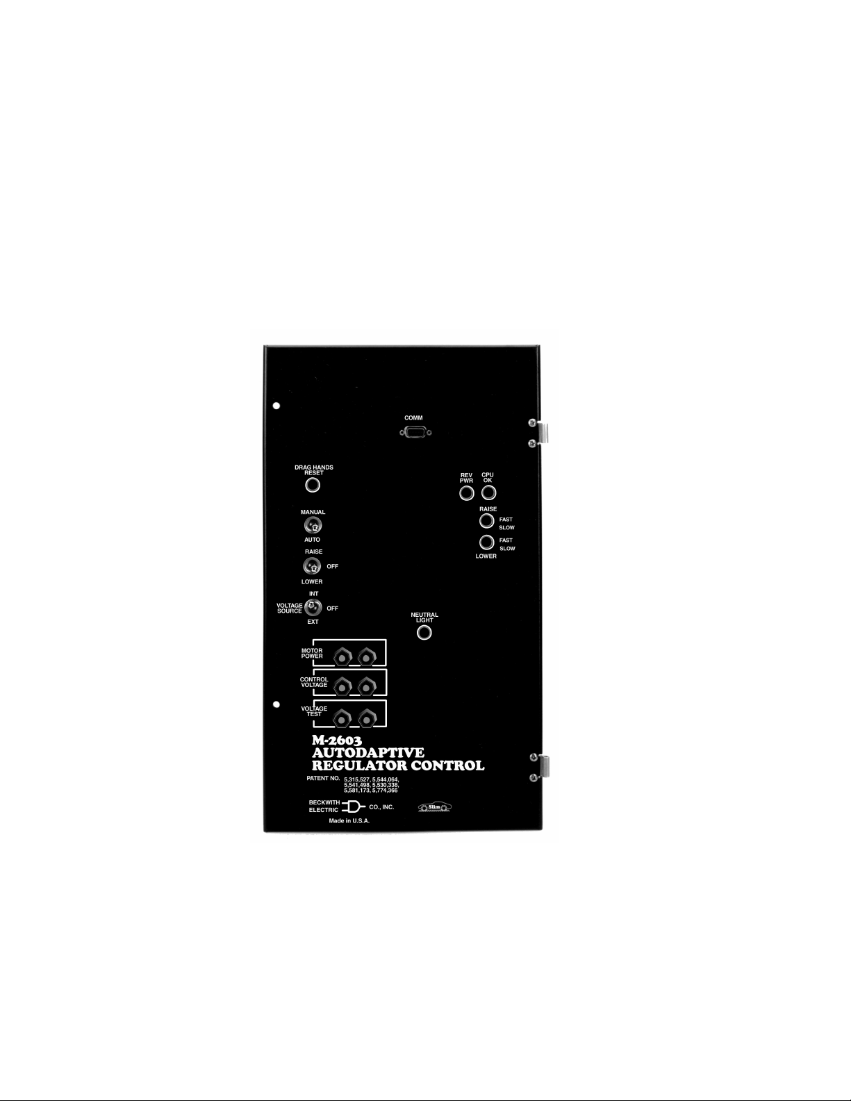
AUTO/MANUAL switch: Selects operational mode of regulator.
RAISE/OFF/LOWER switch: Provides manual tap position control.
VOLTAGE SOURCE: Allows the selection of either an internal or external voltage source.
–2–
Page 12

M-2603 Autodaptive Regulator Control
LED Indicators
The front panel LED indicators alert the user to the following conditions:
Out-of-Band RAISE and LOWER (3 position): GREEN (Initial Timing), AMBER (switch operation in 1 to 5
minutes), RED (switch operation in 1 minute or less).
CPU OK, flashing GREEN, indicates the control is working properly.
REV PWR, RED, indicates a reverse power condition exists.
NEUTRAL LIGHT, AMBER, indicates regulator is in the neutral position.
Output Contacts
Raise Output: Capable of switching 6 A at 120 V ac to 240 V ac motor power.
Lower Output: Capable of switching 6 A at 120 V ac or 240 V ac motor power.
Voltage Measurement Accuracy
Voltage accuracy of K0.7% in accordance with ANSI/IEEE C57.15-1986 defining control accuracy of
operation.
Communications
Serial communications is available via a front panel-mounted, optically-isolated RS-232 serial data port in a
DE 9-pin configuration, with available data rate of 9600 baud.
Environmental
Temperature: Stated accuracies maintained from –40°C to +80°C.
Humidity: Stated accuracies are maintained up to 95% relative humidity (non-condensing).
Fungal Resistance: A conformal coating is used on the printed circuit board to inhibit fungal growth.
Transient Protection
High Voltage: All input and output terminals will withstand 1500 V ac to chassis or instrument ground for one
minute, for all terminals to ground with a leakage current of less than 25 mA. Input and output circuits are
electrically isolated from each other, from other circuits and from ground.
Surge Withstand Capability: All input and output circuits are protected against system transients. Units
pass all requirements of ANSI/IEEE C.37.90.1-1989 defining surge withstand capability.
Radiated Electromagnetic Withstand Capability: All units are protected against electromagnetic radiated
interference from portable communications transceivers.
Electrostatic Discharge Sensitivity: Per IEC 1000–4.
Physical
Size: 17-5/8" high x 10-1/8" wide x 2-3/8" deep (52.71 cm x 25.72 cm x 5.6 cm)
Mounting: Mechanically interchangeable with existing Cooper equipment.
Approximate Weight: 4 lbs, 13 oz (2.18 kg)
Approximate Shipping Weight: 10 lbs (4.54 kg)
–3–
Page 13

Accessories
M-2802 SLIMcom® for Windows
M-2808 SLIMcom for Visor
Metering
The following measured and calculated parameters are available in real-time:
• PrimaryVoltage • Primary Current • Power Factor
• KWatts** • KVArs** • KVA**
• Secondary Voltage • Secondary Current • VRQF
• CT Phasing • Avg Taps/Day • Tap Position
• Preset Counter • Alarm Status • Voltage Profile
Historical Data Plot
• Up to seven time-stamped analog calculated or measured values
• 1 digital parameter can be plotted
■ NOTE: All stored data available with time stamp. Five minute averaged samples are stored 111 days.
Sampling rate adjustable from 5 to 60 minutes, with resultant change to storage period.
Voltage Outage Plot
• Voltage plots (previous 10 seconds of data) for the last 4 voltage outage events are displayed.
Tap Statistics Plot
• The Tap Statistics Plot presents a graphical representation of tap position usage history.
™
™
✝
Other
• Prints detailed reports of all setpoints and data.
• Entry and Readout of setpoints.
**Value calculated in SLIMcom
✝
VRQF is the RMS deviation in the fundamental component of an AC voltage from a desired AC voltage. It is computed as the
square root of the sum of the squares of deviations in the fundamental component of the voltage from the desired value. The
sum is computed as a running recursive average of frequently taken samples of the fundamental component, obtained in at
least one full cycle of the wave. The time constant of the recursive computation is 6 hours. The recursive average takes at
least six hours to settle to a proper sum, and is generally never stopped, once started.
.
All primary quantities are also calculated in SLIMcom.
M-2931 Handspring™ Visor™ Deluxe, with SLIMcom for Visor Communications Software
Patents
The M-2603 Autodaptive® Regulator Control is covered by U.S. Patents, 5,315,527, 5,554,064, 5,541,498
and 5,530,338 with other patents pending.
Warranty
The M-2603 Autodaptive Regulator Control is covered by a two year warranty from date of shipment.
Specification subject to change without notice.
BECKWITH ELECTRIC CO., INC.
6190 - 118th Avenue North • Largo, Florida 33773–3724 U.S.A.
Phone (727) 544-2326 • FAX (727) 546-0121
E-MAIL [email protected]
WEB PAGE www.beckwithelectric.com
© 2000 Beckwith Electric Co.
Printed in U.S.A.
800-2603-SP-01 09/01
Page 14

WARNING
DANGEROUS VOLTAGES, capable of causing death or serious
injury, are present on the external terminals and inside the equipment. Use extreme caution and follow all safety rules when handling, testing or adjusting the equipment. However, these internal
voltage levels are no greater than the voltages applied to the external terminals.
DANGER! HIGH VOLTAGE
– This sign warns that the area is connected to a dangerous high voltage, and you
must never touch it.
PERSONNEL SAFETY PRECAUTIONS
The following general rules and other specific warnings throughout the manual must be followed during application,
test or repair of this equipment. Failure to do so will violate standards for safety in the design, manufacture, and intended
use of the product. Qualified personnel should be the only ones who operate and maintain this equipment. Beckwith
Electric Co., Inc. assumes no liability for the customer’s failure to comply with these requirements.
– This sign means that you should refer to the corresponding section of the operation
manual for important information before proceeding.
Always Ground the Equipment
To avoid possible shock hazard, the chassis must be connected to an electrical ground. When servicing
equipment in a test area, the Protective Earth Terminal must be attached to a separate ground securely
by use of a tool, since it is not grounded by external connectors.
Do NOT operate in an explosive environment
Do not operate this equipment in the presence of flammable or explosive gases or fumes. To do so would
risk a possible fire or explosion.
Keep away from live circuits
Operating personnel must not remove the cover or expose the printed circuit board while power is applied. In no case may components be replaced with power applied. In some instances, dangerous voltages may exist even when power is disconnected. To avoid electrical shock, always disconnect power and
discharge circuits before working on the unit.
Exercise care during installation, operation, & maintenance procedures
The equipment described in this manual contains voltages high enough to cause serious injury or death.
Only qualified personnel should install, operate, test, and maintain this equipment. Be sure that all personnel safety procedures are carefully followed. Exercise due care when operating or servicing alone.
Do not modify equipment
Do not perform any unauthorized modifications on this instrument. Return of the unit to a Beckwith
Electric repair facility is preferred. If authorized modifications are to be attempted, be sure to follow
replacement procedures carefully to assure that safety features are maintained.
Page 15

PRODUCT CAUTIONS
Before attempting any test, calibration, or maintenance procedure, personnel must be completely familiar
with the particular circuitry of this unit, and have an adequate understanding of field effect devices. If a
component is found to be defective, always follow replacement procedures carefully to that assure safety
features are maintained. Always replace components with those of equal or better quality as shown in the
Parts List of the Instruction Book.
Avoid static charge
This unit contains MOS circuitry, which can be damaged by improper test or rework procedures. Care
should be taken to avoid static charge on work surfaces and service personnel.
Use caution when measuring resistances
Any attempt to measure resistances between points on the printed circuit board, unless otherwise noted
in the Instruction Book, is likely to cause damage to the unit.
Page 16

Table of Contents
M-2601/02/03 Autodaptive® Regulator
Control
Instruction Book
Chapter 1 Introduction
1.0 Description .......................................................................................... 1–1
Use of LDC ......................................................................................... 1–2
1.1 Accessories........................................................................................ 1–2
Chapter 2 Front Panel Controls
2.0 Introduction ......................................................................................... 2–1
Table of Contents
2.1 COMM Port......................................................................................... 2–1
2.2 Status Indicators ................................................................................ 2–1
Chapter 3 Installation
3.0 Installation .......................................................................................... 3–1
3.1 Installation of the M-2601 .................................................................. 3–1
Removal of the Siemens Control ...................................................... 3–1
Installation of the M-2601 .................................................................. 3–4
3.2 Installation of the M-2602 .................................................................. 3–6
Removal of the General Electric Control .......................................... 3–7
Installation of the M-2602 .................................................................. 3–8
3.3 Installation of the M-2603 ................................................................ 3–10
Removal of the Cooper Control ....................................................... 3–11
Installation of the M-2603 ................................................................ 3–12
3.4 Transient Protection ......................................................................... 3–14
3.5 External Connections ....................................................................... 3–14
i
Page 17

M-2601/02/03 Autodaptive Regulator Control Instruction Book
Chapter 4 Applications
4.0 Introduction ......................................................................................... 4–1
VRQF .................................................................................................. 4–1
VAr Bias ............................................................................................. 4–2
4.1 Measurements & Calculations ........................................................... 4–2
Voltage Measurements ...................................................................... 4–2
Current Measurements ....................................................................... 4–2
Rails and Limits ................................................................................. 4–3
4.2 Voltage Regulation ............................................................................. 4–3
Standard Control Settings .................................................................. 4–3
Password Applicability ....................................................................... 4–3
Bandcenter .......................................................................................... 4–3
Voltage Regulation Without LDC ....................................................... 4–3
Voltage Regulation With LDC ............................................................ 4–3
4.3 Regulation Limits ................................................................................ 4–5
Upper Voltage Limit............................................................................ 4–5
Lower Voltage Limit............................................................................ 4–5
Tap Position Limits ............................................................................ 4–5
4.4 Non-Sequential/Blocking .................................................................... 4–5
4.5 Counters.............................................................................................. 4–5
Operations Counter ............................................................................ 4–5
4.6 CT/VT Phase Shift ............................................................................. 4–5
4.7 Ratio Multipliers.................................................................................. 4–6
VT User Correction Voltage ............................................................... 4–6
CT User Correction Voltage ............................................................... 4–6
Primary Voltage and Current Multipliers ........................................... 4–6
4.8 Tap Position ....................................................................................... 4–6
Tap Position by Keep Track.............................................................. 4–6
Chapter 5 Communications
5.0 Introduction ......................................................................................... 5–1
Chapter 6 Field Operation Verification
6.0 Bench Test ......................................................................................... 6–1
6.1 Post-Installation Test ......................................................................... 6–4
ii
Page 18

Chapter 7 SLIMcom™
7.0 Introduction ......................................................................................... 7–1
7.1 Installation and Setup ........................................................................ 7–1
Hardware Requirements ..................................................................... 7–1
Installation .......................................................................................... 7–3
System Setup..................................................................................... 7–3
7.2 Description .......................................................................................... 7–3
Primary Status.................................................................................... 7–4
Secondary Status ............................................................................... 7–4
Tap Position Clock............................................................................. 7–4
Alarm LED Indicators ......................................................................... 7–4
Biasing Display Bar............................................................................ 7–4
Timing and Misc Display Bar ............................................................ 7–4
File Menu ............................................................................................ 7–5
Load Data Submenu ........................................................................... 7–5
Setup Menu ........................................................................................ 7–7
Security Menu .................................................................................... 7–7
Change Passwords Command ........................................................... 7–8
Password Entry Command ................................................................ 7–8
Commands Menu................................................................................ 7–8
Setpoints Command ........................................................................... 7–8
Parameters.......................................................................................... 7–9
Alarms ............................................................................................... 7–10
Time .................................................................................................. 7–10
Counters............................................................................................ 7–10
VAr Control ....................................................................................... 7–10
Inhibit On/Off .................................................................................... 7–10
Voltage Bias Command ................................................................... 7–10
Selections Command ....................................................................... 7–11
Graph Selections Table ................................................................... 7–11
Metering Setpoints Selection Table ................................................ 7–12
Erase Control Submenu ................................................................... 7–12
Retrieve Data Menu ......................................................................... 7–12
History Data...................................................................................... 7–12
Outage Data ..................................................................................... 7–12
Tap Statistics ................................................................................... 7–12
Metering Data ................................................................................... 7–12
M-2501 Import .................................................................................. 7–12
Window Menu ................................................................................... 7–13
Help Menu......................................................................................... 7–13
Table of Contents
Appendix A Communications
A.0 Null Modem Cable ..............................................................................A–1
iii
Page 19

M-2601/02/03 Autodaptive Regulator Control Instruction Book
Figures Page
Chapter 1 Introduction
1-1 Functional Diagram ........................................................................... 1–2
Chapter 2 Front Panel
2-1 M-2601 Front Panel............................................................................ 2–2
Chapter 3 Installation
3-1 M-2601 Outline Dimensions ............................................................... 3–2
3-2 Siemens Control in Cabinet ............................................................... 3–3
3-3 M-2601 Autodaptive® Regulator Control in Cabinet .......................... 3–4
3-4 M-2601 External Connections............................................................ 3–5
3-5 M-2602 Outline Dimensions ............................................................... 3–6
3-6 General Electric Control in Cabinet ................................................... 3–7
3-7 M-2602 Autodaptive Regulator Control in Cabinet ............................ 3–8
3-8 M-2602 External Connections............................................................ 3–9
3-9 M-2603 Outline Dimensions ............................................................. 3–10
3-10 Cooper Control in Cabinet ................................................................ 3–11
3-11 M-2603 Autodaptive Regulator Control in Cabinet .......................... 3–12
3-12 M-2603 External Connections .......................................................... 3–13
Chapter 6 Test Procedure
6-1 External Connections for Test Procedure ......................................... 6–2
Chapter 7 SLIMcom™
7-1 SLIMCom Main Menu Flow................................................................ 7–2
7-2 Metering Status Screen ..................................................................... 7–3
7-3 History Data Screen........................................................................... 7–5
7-4 Tap Statistics Screen ........................................................................ 7–6
7-5 Outage Screen.................................................................................... 7–6
7-6 Setup Communications Screen ......................................................... 7–7
7-7 Identification Dialog ............................................................................ 7–7
iv
7-8 Change Level Access Code .............................................................. 7–8
7-9 Passwords Entry Submenu................................................................ 7–8
Page 20

Table of Contents
Figures (
cont
) Page
Chapter 7 SLIMcom (
cont
)
7-10 Setpoints Dialog Box ......................................................................... 7–9
7-11 Tap Position Setpoints .................................................................... 7–11
7-12 Graph Selections .............................................................................. 7–11
7-13 Metering Selections.......................................................................... 7–12
7-14 Metering Data ................................................................................... 7–13
Appendix A Communications
A-1 Null Modem Cable, 9-pin to 9-pin ...................................................... A–1
Tables Page
4-1 Level 1 Password Adjustable Parameters ........................................ 4–4
4-2 Approximate Ratio of Line Reactance to
Resistance (X/R) of Typical Distribution Circuits ............................. 4–4
© 2000 Beckwith Electric Co.
Printed in U.S.A. (11.06.00)
800-2601/02/03-IB-00 11/00
v
Page 21

This Page Left Intentionally Blank
Page 22

1.0 Description ................................................................................ 1–1
1.1 Accessories ............................................................................... 1–2
1.0 Description
Introduction – 1
1 Introduction
The Beckwith M-2601/02/03 Series of Autodaptive
Regulator Controls (ARC) are unique
microcontroller-based solutions to regulator control
requirements. Using conventional inputs, the control
accomplishes regulator control, based on voltage.
The unit has a user-defined Bandcenter and
Voltage Regulation Quality Factor (VRQF) that
permits optimization of the tapchanging process,
as well as a variety of configuration setpoints to
allow maximum flexibility.
The ARC senses voltage and current which permits
the control of voltage through the regulator. The
control utilizes nonlinear integrating algorithms
which adapt to system operating conditions to
reduce the number of tapchanger operations while
maintaining the desired VRQF.
The ARC is protected from noise and transients
likely to be found in typical regulator control
applications. The control is designed to withstand
the application of 1500 V ac for one minute between
any terminal and ground connection, and meets
or surpasses the requirements of ANSI/IEEE
C.37.90.1-1989, which define surge withstand
capability.
®
Interrogation of the control and setting changes
are made through an optically-isolated RS-232
communications port mounted on the front of the
unit. Using the M-2802 SLIMcom™ software, with
a computer running Microsoft® Windows 95/98,
the user can configure and monitor operation of
the unit. Two passwords are available to the user
and are accessed through the communications
port. All setpoints are stored in nonvolatile memory
which is unaffected by control voltage disturbances.
Two operation counters are provided. One counter
may be reset; the other may be preset. The control
has adjustable bandcenter, over and undervoltage,
runback, and line drop compensation.
Nine LEDs are used to indicate Regulator RAISE
and LOWER (Fast, Intermediate and Slow)
command status, CPU OK, REV PWR, and
NEUTRAL LIGHT.
The basic control settings allow regulation of the
voltage at a remote location while assuring that
the customer nearest the regulator is protected
against overvoltage.
The control has a VT User Correction Voltage
setting, and the capability to correct for current
transformer and voltage transformer phasing
connections without making wiring changes. This
feature allows phase angle corrections in 30°
increments from 0° to 330°.
1–1
Page 23
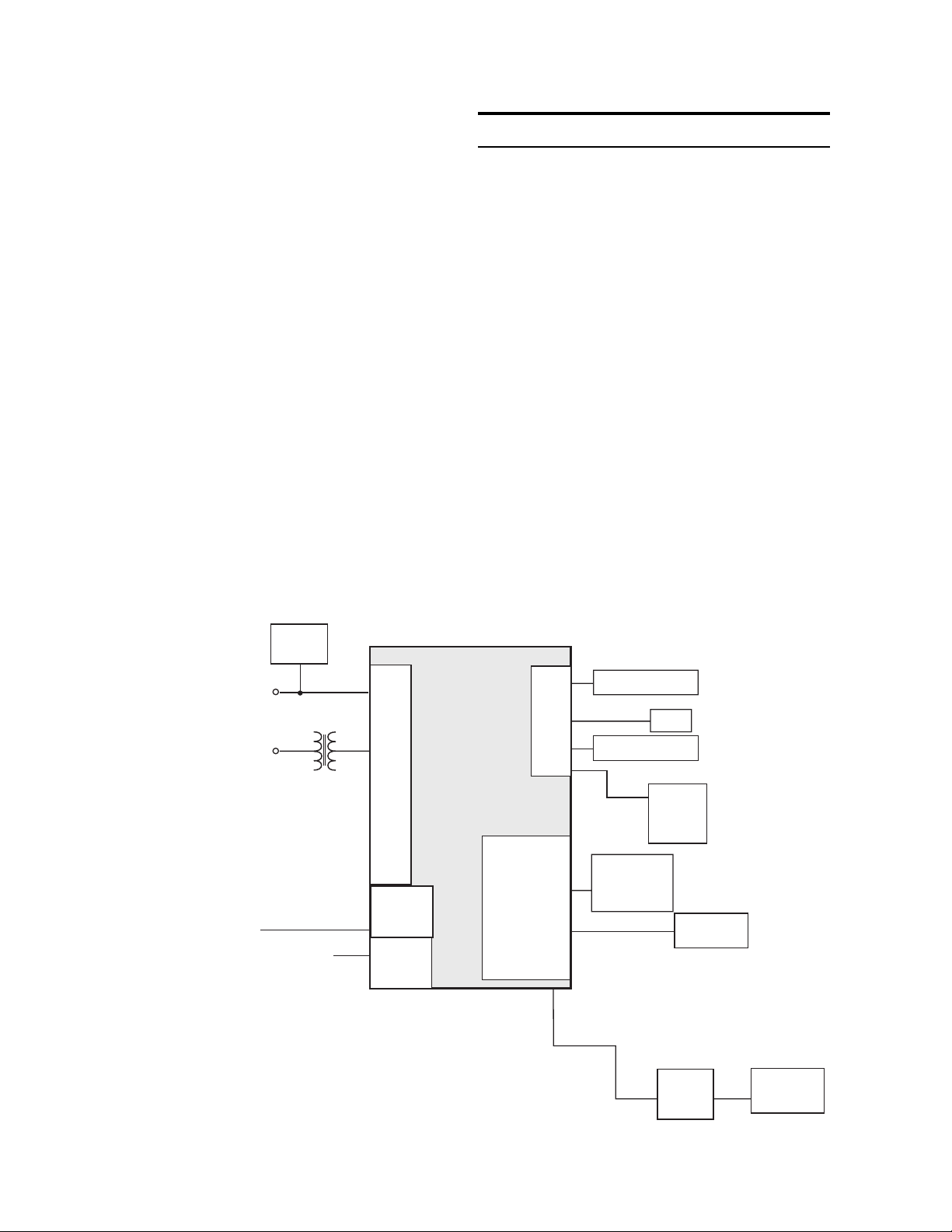
M-2601/02/03 Instruction Book
The Autodaptive® Regulator Control uses a
Motorola microcontroller which has a self-testing
watchdog system, which is illustrated in Figure
1-1, below.
Use of LDC
The use of Line Drop Compensation (LDC) is
outlined in Section 4.2, Voltage Regulation. This
feature is recommended for use on regulators
connected to distribution feeders which have
switched capacitor banks that are controlled by
Beckwith M-2501 Series Autodaptive Capacitor
Controls, placed beyond the theoretical load center,
or where other methods of cap bank control are
used.
1.1 Accessories
M-2802 SLIMcom™
Communications
Software
SLIMcom is a Windows™–based communications
software package required for remote control and
metering of the Autodaptive Regulator Control
(ARC). It is designed to interface with the
microcontroller of the ARC through an RS-232 port.
The M-2802 SLIMcom communications software
displays all pertinent operating information. These
operations include:
• Changing setpoint values. (This includes
those values for normal regulator control
operation, as well as custom configuration
to the site.)
• Observing values. (This includes measured
and calculated values of real-time operating
parameters.)
• Data retrieval and display in graphic form.
Input
Voltage
Line
Current
Interface Digital
Outputs
Power
Supply
Digital
Inputs
CT
A/D
I
n
p
u
t
s
Digital
output
Digital
Inputs
Microcontroller
• Outage Data.
Flash Memory
B
u
s
History Storage
I/O
RAISE &
LOWER
Outputs
Outputs
RAM
Real
Time
Clock
Status
LEDs
1–2
Figure 1-1 Functional Diagram
Optical
Isolation
RS-232
Page 24

Front Panel Controls – 2
2 Front Panel Controls
2.0 Introduction ............................................................................... 2–1
2.1 COMM Port ............................................................................... 2–1
2.2 Status Indicators ....................................................................... 2–1
1
2.0 Introduction
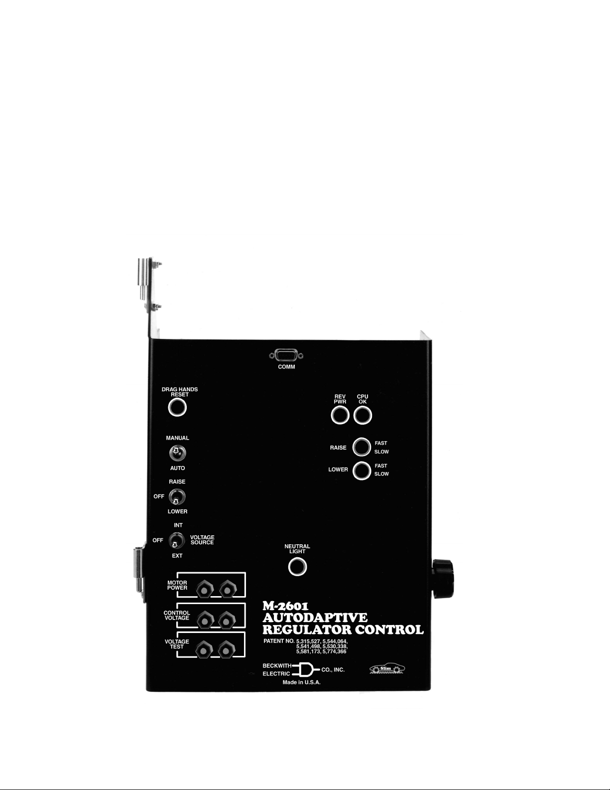
The front-panel user interface consists of an
RS-232 serial communications port and five status
indicators as shown in Figure 2-1, M-2601 Front
Panel (M-2602 and M-2603 each possess identical
user interface).
2.1 COMM Port
The RS-232 serial communications port is located
at the top of the Autodaptive® Regulator Control
front panel. Connections are made through a
standard DE-9 type female connector. The pinout
is of the computer type (DTE) configuration, and
will typically require a null-modem type cable. See
Appendix A, Null Modem Cable for pinout.
2.2 Status Indicators
RAISE LEDs – These LEDs indicate that the voltage
is below the band and the timer has started timing
for a tapchanger raise operation. The timer circuit
first illuminates a GREEN LED, to indicate the
initial timing phase, which is greater than 5 minutes
to the anticipated switch operation. The middle
timing period is indicated by an AMBER LED, which
anticipates a switch operation in one to five minutes,
and the final timing phase prior to switching is
indicated by illuminating a RED LED, which
anticipates a switch operation in less than 1 minute.
2–1
Page 25
M-2601/02/03 Instruction Book
LOWER LEDs – These LEDs indicate that the
voltage is above the band and the timer has started
timing for a tapchanger lower operation. The timer
circuit first illuminates a GREEN LED, to indicate
the initial timing phase, which is greater than 5
minutes to the anticipated switch operation. The
middle timing period is indicated by an AMBER
LED, which anticipates a switch operation in one
to five minutes, and the final timing phase prior to
switching is indicated by illuminating a RED LED,
which anticipates a switch operation in less than
1 minute.
CPU OK LED – The GREEN LED will flash at
approximately 1 Hz whenever power is applied to
the unit and the watchdog program (internal to the
microcontroller), indicates the microcontroller is
working properly.
Each time the control is powered up, it will briefly
light all LED's to verify that LED indicators are
functioning properly. After that brief period, the CPU
OK LED will begin flashing.
REV PWR LED – The RED LED will light to indicate
when the unit detects reverse power flow.
NEUTRAL LIGHT LED – This AMBER LED will light
when the regulator is in the neutral tap position.
2–2
Figure 2-1 M-2601 Front Panel
Page 26

3 Installation
3.0 Installation ................................................................................. 3–1
3.1 Installation of the M-2601......................................................... 3–1
3.2 Installation of the M-2602......................................................... 3–6
3.3 Installation of the M-2603....................................................... 3–10
3.4 Transient Protection ............................................................... 3–14
3.5 External Connections ............................................................. 3–14
Installation – 3
3.0 Installation
Individual installation instructions for the M-2601
(Siemens), M-2602 (General Electric), and M-2603
(Cooper) are presented in Sections 3.1, 3.2 and
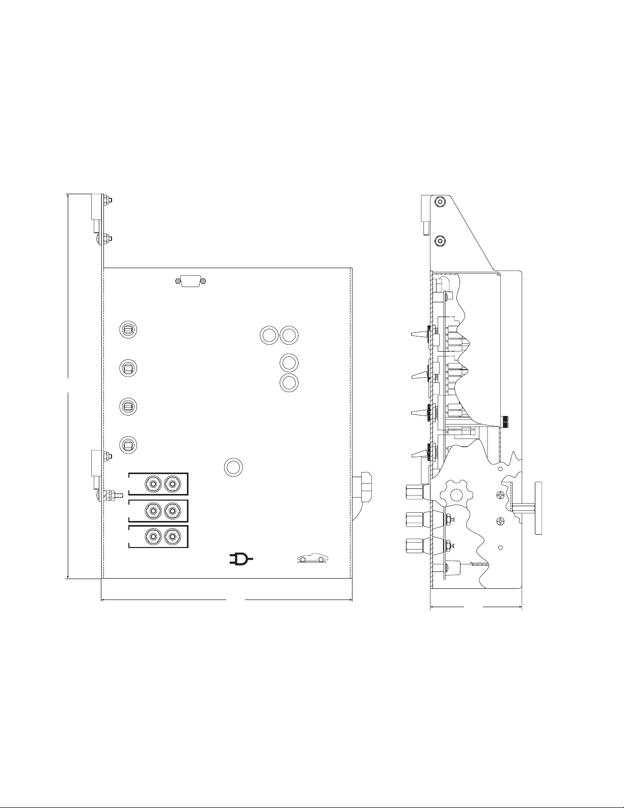
3.3 respectively. Mounting and outline dimensions
are shown in Figures 3-1, 3-5 and 3-9.
& WARNING: In no case should the line current circuit be interrupted with the regulator
energized.
& WARNING: Open CT secondary will result in
high voltage at CT terminals. Death, severe
injury or damage to equipment can occur. Do
not operate with CT secondary open. Short
circuit or apply burden at CT secondary during operation.
3.1 Installation of the M-2601
The M-2601 has hinges on the left side that allow
easy mounting into the existing Siemens control
cabinet. Refer to Figure 3-1 for outline dimensions.
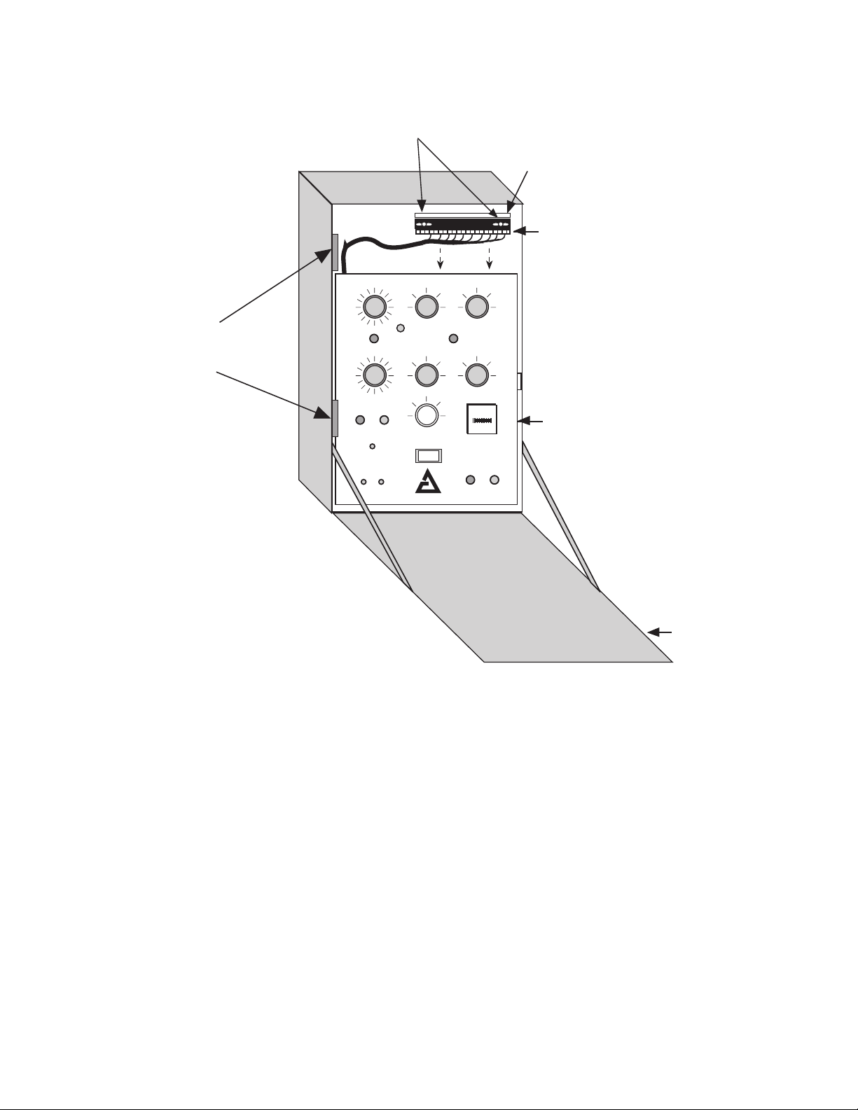
Removal of the Siemens Control
Refer to Figure 3-2.
1. Open the cabinet door of the Siemens control.
2. Remove and save the wing nuts from the
quick disconnect shorting plug located in the
top right of the cabinet.
3. Pull down on the male connector portion of
the plug to disconnect it from its female
connector.
4. Swing the panel out. Lift panel off its hinges.
5. Remove the male connector portion of the
plug by unscrewing its connections to the
Siemens control's wiring harness.
■ NOTE: The quick disconnect shorting plug must
be saved from the original control.
3–1
Page 27
M-2601/02/03 Instruction Book
COMM
DRAG HAN DS
RESET
REV
PWR
CPU
OK
15.00
[38.1]
OFF
OFF
MANUAL
AUTO
RAIS E
LOWER
INT
EXT
MOTOR
POWER
CONTROL
VOLTAGE
VOLTAGE
TEST
VOLTAGE
SOURCE
NEUTRAL
LIGHT
M-2601
AUTODAPTIVE
REGULATOR CONTROL
PATENT NO. 5,315,527, 5,544,064,5,541,498
BECKWITH
ELECT RIC
Made in U.S.A .
9.25
[25.08]
RAIS E
LOWER
5,530,338, 5,646,512, 5,581,173,
5,774,366
CO. INC.
■ NOTE: Dimensions in brackets are in centimeters.
FAS T
SLOW
FAS T
SLOW
lS mi
3.50
[8.9]
3–2
Figure 3-1 M-2601 Outline Dimensions
Page 28
c
Hinges
b
Wing Nuts
Quick Disconnect
Shorting Plug
d
Male Connector
Control Panel
Installation – 3
Cabinet Door
Figure 3-2 Siemens Control in Cabinet
a
3–3
Page 29
M-2601/02/03 Instruction Book
Installation of the M-2601
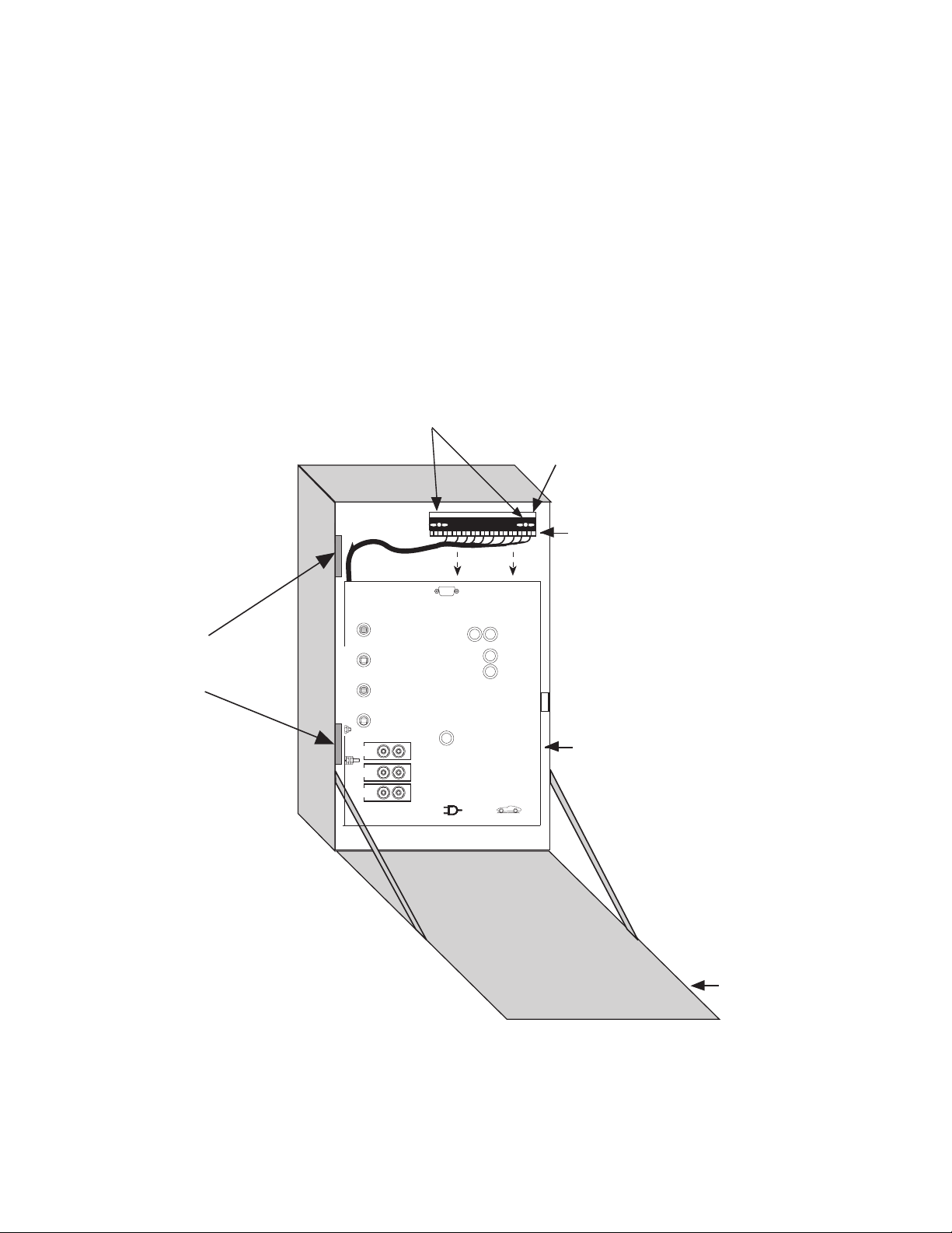
Refer to Figure 3-3, below.
1. Mount the M-2601 Autodaptive® Regulator
Control onto the hinges in the control cabinet. Leave the panel swung outward so that
the back of the panel is accessible.
2. Connect the M-2601 wiring harness to the
male connector, saved from the original
control. Refer to Figure 3-4 for wiring
connections.
Wing Nuts
3. Reinstall the male connector onto the quick
disconnect plug and reinstall the wing nuts.
4. Swing the adapter panel closed; the magnet at the back of the panel will keep the
panel affixed to the cabinet. Close cabinet
door.
c
Quick Disconnect
Shorting Plug
a
Hinges
DRAG HANDS
MANUAL
OFF
OFF
CONTROL
VOLTAGE
VOLTAGE
RESET
RAISE
LOWER
MOTOR
POWER
b
Male Connector
COMM
CPU
REV
OK
PWR
FAST
RAISE
SLOW
AUTO
INT
VOLTAGE
SOURCE
EXT
TEST
NEUTRAL
LIGHT
M-2601
AUTODAPTIVE
REGULATOR CONTROL
PATENT NO.5,315,527, 5,544,064,5,541,498
5,530,338, 5,646,512,5,581,173,
5,774,366
BECKWITH
ELECTRIC
Made in U.S.A.
LOWER
CO. INC.
FAST
SLOW
Autodaptive
Regulator
Control
lS mi
3–4
Cabinet Door
Figure 3-3 M-2601 Autodaptive Regulator Control in Cabinet
d
Page 30
M-2601 SIEMENS
(
)
(
)
(
)
)
(Reg
)
Connection Diagram
Installation – 3
M-2601 TB1 TERMINALS
SIEMENS PLUG TERMINALS
TB1
COUNTER INPUT
LOAD CURRENT
POLARITY
LOAD CURRENT
RETURN
NEUTRAL POSITION
Neutral
NEUTRAL POSITION
Hot
TAPCHANGER LOWER
OUTPUT
NEUTRAL
TAPCHANGER RAISE
OUTPUT
MOTOR HOLD
N/U
U10
C2
E1
U12
OPERATIONS COUNTER SWITCH
LINE
CURRENT
CT SHORTING SWITCH
NEUTRAL LIGHT SWITCH
P2
K
E
J
MOTOR
L
R
CT
NEUTRAL
Motor Return
1
2
3
4
5
6
7
8
9
DRAG HANDS RESET
MOTOR POWER INPUT
VOLTAGE INPUT
10
11
12
U11
POSITION INDICATOR RESET
U2
P2
MOTOR POWER IN (Unregulated 120 V
FROM TERTIARY WINDING
VOLTAGE IN
FROM VT
ulated 120 V
Figure 3-4 M-2601 External Connections
3–5
Page 31
M-2601/02/03 Instruction Book
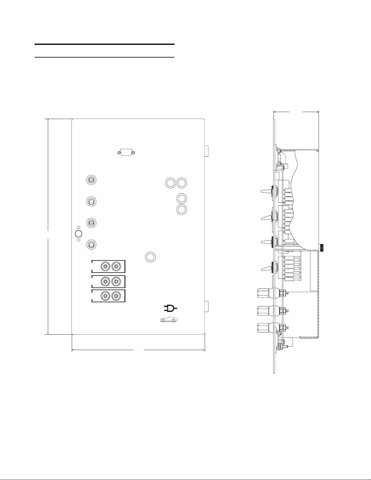
3.2 Installation of the M-2602
The M-2602 Autodaptive® Regulator Control has
hinges on the right side that allow easy mounting
into the existing General Electric control cabinet.
Refer to Figure 3-5, below.
COMM
DRAG HANDS
RESET
REV
PWR
CPU
OK
2.68
[5.6]
15.00
[38.1]
MANUAL
AUTO
RAIS E
OFF
LOWER
INT
VOLTAGE
OFF
SOURCE
EXT
MOTOR
POWER
CONTROL
VOLTAGE
VOLTAGE
TEST
M-2602
AUTODAPTIVE
REGULATOR CONTROL
PATENT NO. 5,315,527 5,544,064, 5,541,498
5,530,338 5,646,512,5,581,173, 5,774,366
9.25
[23.5]
NEUTRAL
LIGHT
BECKWITH
ELECT RIC
Made in U.S.A.
miSl
RAIS E
LOWER
CO. INC.
FAS T
SLOW
FAS T
SLOW
■ NOTE: Dimensions in brackets are in centimeters.
Figure 3-5 M-2602 Outline Dimensions
3–6
Page 32
Installation – 3
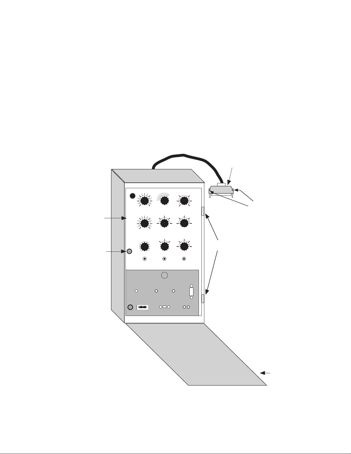
Removal of the General Electric
Control
Refer to Figure 3-6, below.
1. Open the cabinet door of the General Electric control.
2. Loosen the two thumbscrews at the
interface of the control cable plug and
the tap position indicator on the regulator. Pull down on the plug to disconnect it.
Control
Panel
3. Turn the knob on the control panel and swing
the panel outward.
4. Disconnect the three plugs that connect the
wiring harness of the front panel to the component board. Remove all connections from
the component board to the NN terminal
blocks. Using a screwdriver or other appropriate tool, remove the component board.
Remove and save the two hinge pins and
lift the panel off the hinges.
■ NOTE: The two hinge pins must be saved from
the original control.
Control
Cable Plug
b
Thumbscrews
c
Control
Panel
Knob
Hinge Pins
d
GENERAL ELECTRIC
GE
Cabinet Door
Figure 3-6 General Electric Control in Cabinet
a
3–7
Page 33
M-2601/02/03 Instruction Book
Installation of the M-2602
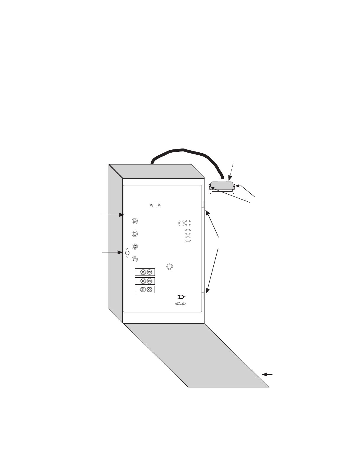
Refer to Figure 3-7, below.
1. Mount the M-2602 Autodaptive® Regulator
Control onto the hinges in the control cabinet, and install the two hinge pins saved from
the original control. Leave the panel swung
outward so that the back of the panel is accessible.
2. Connect the M-2602 wiring harness to the
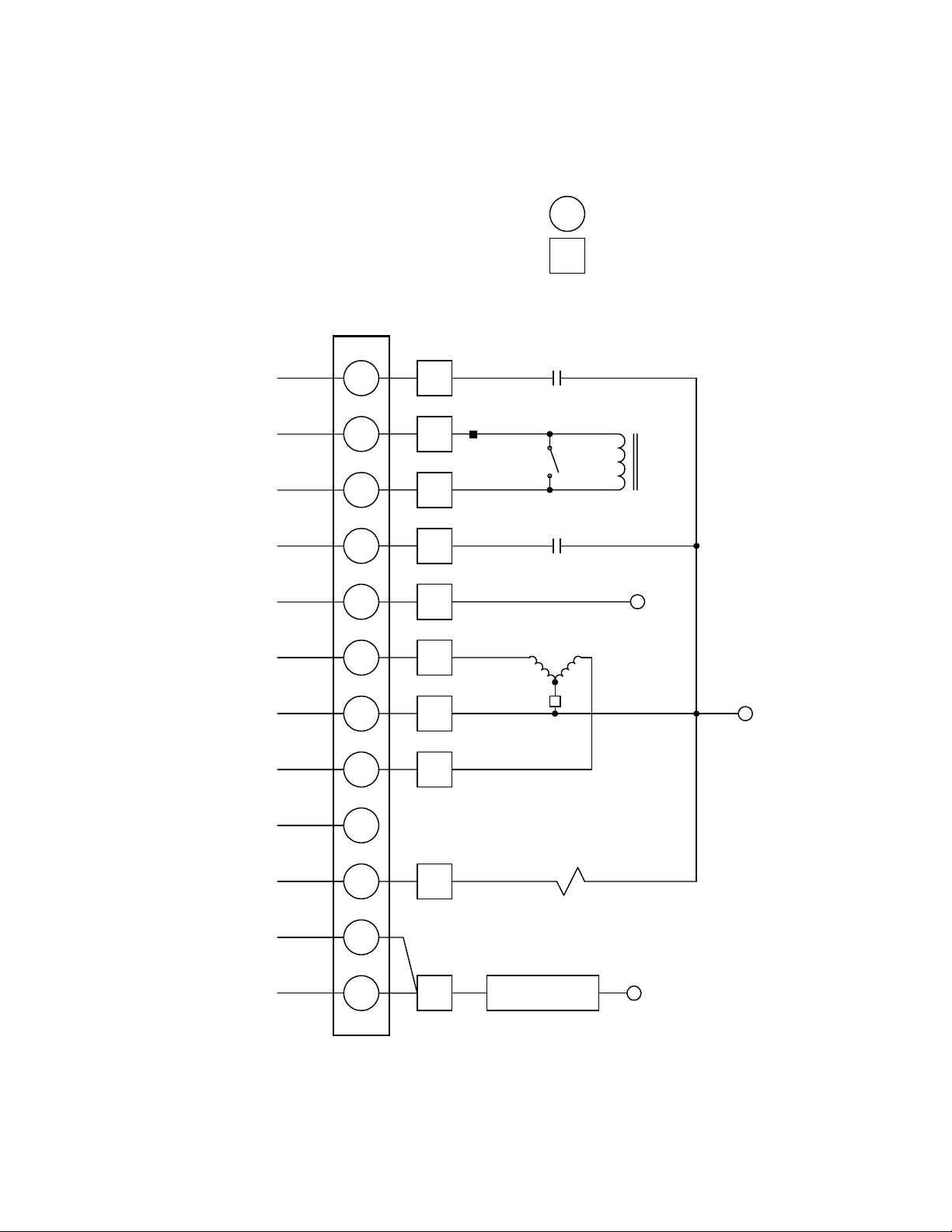
NN terminal blocks. Refer to Figure 3-8 for
COMM
Autodaptive
Regulator
Control
b
Control
Panel
Knob
DRAG HANDS
RESET
MANUAL
AUTO
RAISE
OFF
LOWER
INT
VOLTAGE
OFF
SOURCE
EXT
MOTOR
POWER
CONTROL
VOLTAGE
VOLTAGE
TEST
M-2602
AUTODAPTIVE
REGULATOR CONTROL
PATENT NO. 5,315,527 5,544,064, 5,541,498
5,530,338 5,646,512,5,581,173, 5,774,366
NEUTRAL
LIGHT
wiring connections. Swing the control panel
closed and turn knobs to latch securely.
3. Reconnect control cable plug to tap position
indicator and tighten the two thumbscrews.
4. Close cabinet door.
Control
Cable Plug
c
Thumbscrews
Hinge Pins
BECKWITH
ELECTRIC
REV
PWR
Made in U.S.A.
miSl
CPU
OK
RAISE
LOWER
CO. INC.
FAST
SLOW
FAST
SLOW
a
3–8
Cabinet Door
Figure 3-7 M-2602 Autodaptive Regulator Control in Cabinet
d
Page 34
M-2602 GENERAL ELECTRIC
Connection Diagram
TB1
Installation – 3
M-2602 TB1 TERMINALS
GENERAL ELECTRIC PLUG TERMINALS
COUNTER INPUT
LOAD CURRENT
POLARITY
LOAD CURRENT
RETURN
NEUTRAL POSITION
(Neutral)
NEUTRAL POSITION
(Hot)
TAPCHANGER LOWER
OUTPUT
NEUTRAL
TAPCHANGER RAISE
OUTPUT
MOTOR HOLD
N/U
30
OPERATIONS COUNTER SWITCH
23
LINE
CURRENT
24
31
9
28
10
27
CT SHORTING SWITCH
NEUTRAL LIGHT SWITCH
120 V ac IN
MOTOR
L
R
CT
NEUTRAL
(Motor Return)
1
2
3
4
5
6
7
8
9
DRAG HANDS RESET
MOTOR POWER INPUT
VOLTAGE INPUT
10
29
POSITION INDICATOR RESET
11
12
9
20, 21 or 22
on T.C.
Figure 3-8 M-2602 External Connections
VOLTAGE IN (Regulated 120 V)
FROM VT
3–9
Page 35
M-2601/02/03 Instruction Book
3.3 Installation of the M-2603
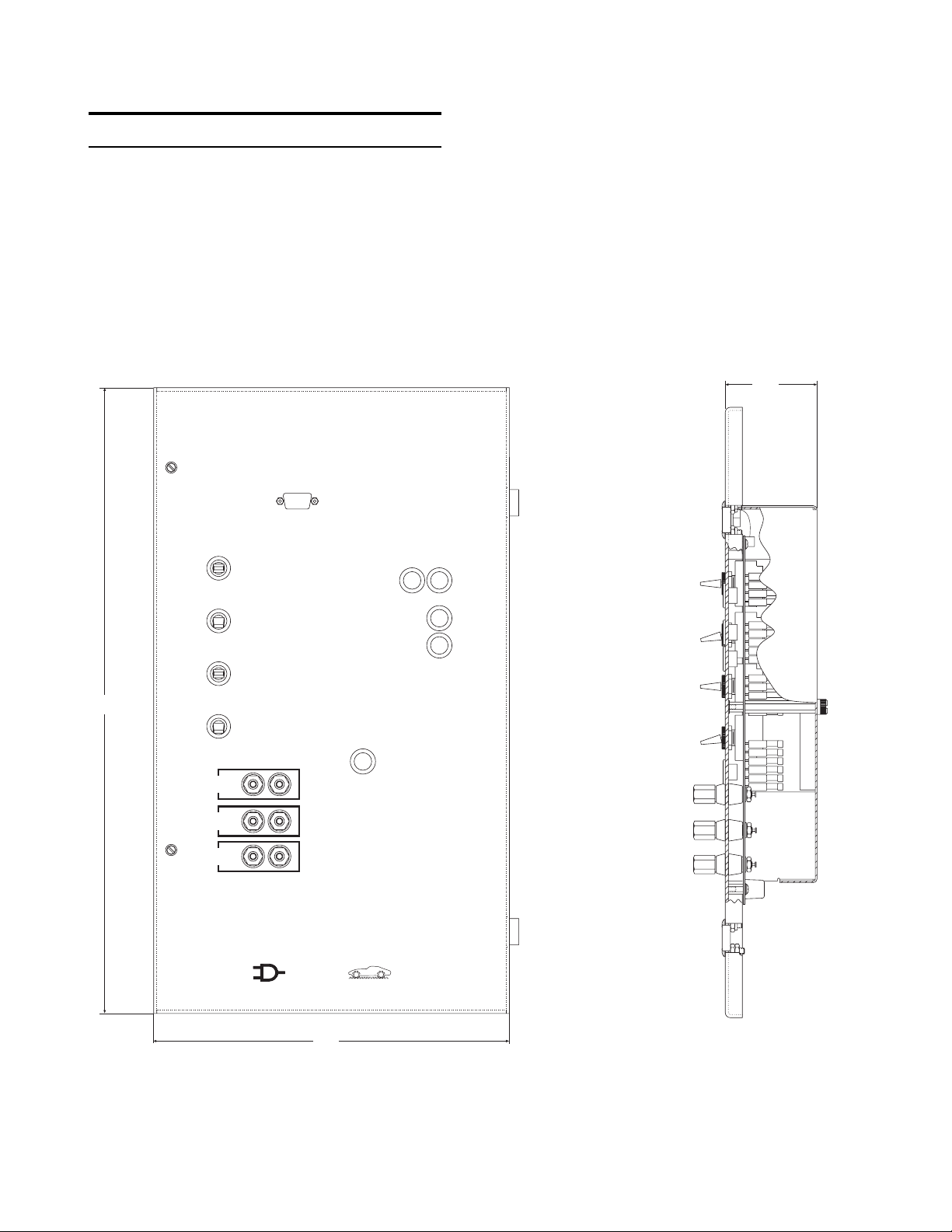
The M-2603 Autodaptive® Regulator Control has
hinges on the right side that allow easy mounting
into the existing Cooper control cabinet. Refer to
Figure 3-9, below.
COMM
5.6
[2.68]
17.80
[52.71]
DRAG HANDS
RESET
MANUAL
AUTO
RAIS E
OFF
LOWER
INT
VOLTAGE
SOURCE
EXT
MOTOR
POWER
CONTROL
VOLTAGE
VOLTAGE
TEST
OFF
M-2603
AUTODAPTIVE
REGULATOR CONTROL
PATENT NO. 5,315,527, 5,544,064, 5,541,498
5,530,338, 5,646,512, 5,581,173, 5,774,366
BECKWITH
ELECT RIC
Made in U.S.A.
CO. INC.
NEUTRAL
LIGHT
lS mi
REV
PWR
CPU
OK
RAIS E
LOWER
FAS T
SLOW
FAS T
SLOW
10.13
[25.72]
■ NOTE: Dimensions in brackets are in centimeters.
Figure 3-9 M-2603 Outline Dimensions
3–10
Page 36
Removal of the Cooper Control
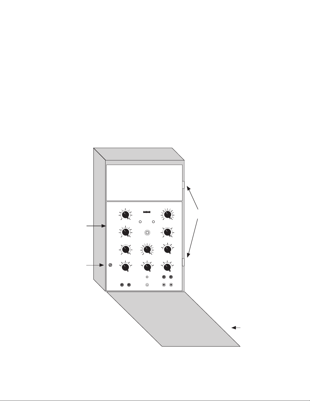
Refer to Figure 3-10, below.
Installation – 3
1. Open the cabinet door of Cooper control.
2. Turn the doorknob on the control panel and
swing the panel outward. To de-energize the
control, open the VT disconnect switch and
put the CT switch in the shorting position.
Be sure that the CT in the regulator has been
shorted.
3. Loosen the screws on the spreader bar
terminal block at the bottom of the cabinet
and pull down on the spreader bar to
disconnect it.
4. Remove and save the two hinge pins and
lift the panel off the hinges.
■ NOTE: The two hinge pins must be saved from
the original control.
Control
Panel
b
Control
Panel
Knob
d
McGRAW-EDISON
CL-2
Cabinet Door
Figure 3-10 Cooper Control in Cabinet
Hinge Pins
1
3–11
Page 37
M-2601/02/03 Instruction Book
Installation of the M-2603
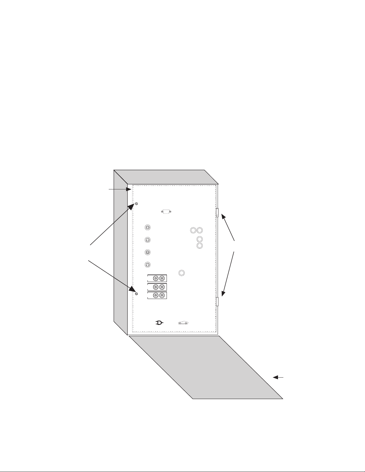
Refer to Figure 3-11, below.
1. Mount the M-2603 Autodaptive® Regulator
Control onto the hinges in the control cabinet and install the two hinge pins saved from
the original control. Leave the panel swung
outward so that the back of the panel is accessible.
2. Connect the M-2603 wiring harness to the
terminal block at the bottom of the cabinet.
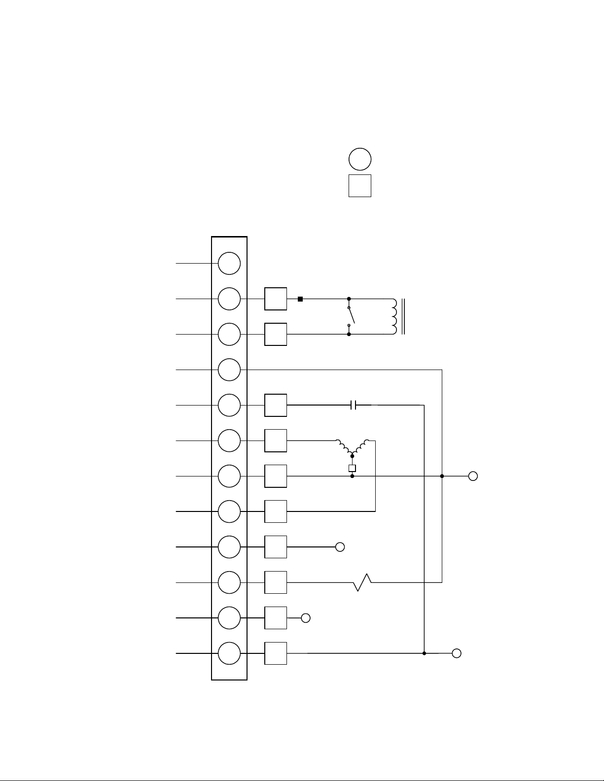
Refer to Figure 3-12 for wiring connections.
Autodaptive
Regulator
Control
COMM
DRAG HANDS
RESET
MANUAL
Control Panel
b
Thumbscrews
AUTO
RAISE
OFF
LOWER
INT
VOLTAGE
OFF
SOURCE
EXT
MOTOR
POWER
CONTROL
VOLTAGE
VOLTAGE
TEST
M-2603
AUTODAPTIVE
REGULATOR CONTROL
PATENT NO. 5,315,527, 5,544,064, 5,541,498
5,530,338, 5,646,512, 5,581,173, 5,774,366
BECKWITH
ELECTRIC
Made in U.S.A.
CO. INC.
3. To re-energize the control, open the CT
switch, removing the CT short circuit, and
close the VT disconnect switch. Swing the
adapter panel closed and turn thumbscrews
to latch securely.
4. Close cabinet door.
CPU
REV
OK
PWR
RAISE
FAST
SLOW
FAST
NEUTRAL
LIGHT
SLOW
LOWER
lS mi
Hinge Pins
a
3–12
Cabinet Door
Figure 3-11 M-2603 Autodaptive Regulator Control in Cabinet
d
Page 38
M-2603 COOPER
Connection Diagram
Installation – 3
M-2603 TB1 TERMINALS
COOPER PLUG TERMINALS
TB1
COUNTER INPUT
LOAD CURRENT
POLARITY
LOAD CURRENT
RETURN
NEUTRAL POSITION
(Neutral)
NEUTRAL POSITION
(Hot)
TAPCHANGER LOWER
OUTPUT
NEUTRAL
TAPCHANGER RAISE
OUTPUT
MOTOR HOLD
N/U
1
2
3
C3
LINE
CURRENT
C1
CT SHORTING SWITCH
CT
4
5
6
7
8
9
NL
R3
HS
NEUTRAL LIGHT SWITCH
L3
G
MOTOR
L
MOTOR SEAL-IN
R
SWITCH
NEUTRAL
(Motor Return)
DRAG HANDS RESET
MOTOR POWER INPUT
VOLTAGE INPUT
10
11
12
DHR
VM
VS
POSITION INDICATOR RESET
MOTOR POWER IN
(Unregulated 120 V)
Figure 3-12 M-2603 External Connections
VOLTAGE IN
(Regulated 120 V-FPF)
3–13
Page 39

M-2601/02/03 Instruction Book
3.4 Transient Protection
In the Autodaptive® Regulator Control, transient
voltages are suppressed by varistors.
Multiple VT grounds far apart must be avoided,
however, since a varying difference in ground
potential could add or subtract from the effective
potential and cause a variation in the voltage
setpoint.
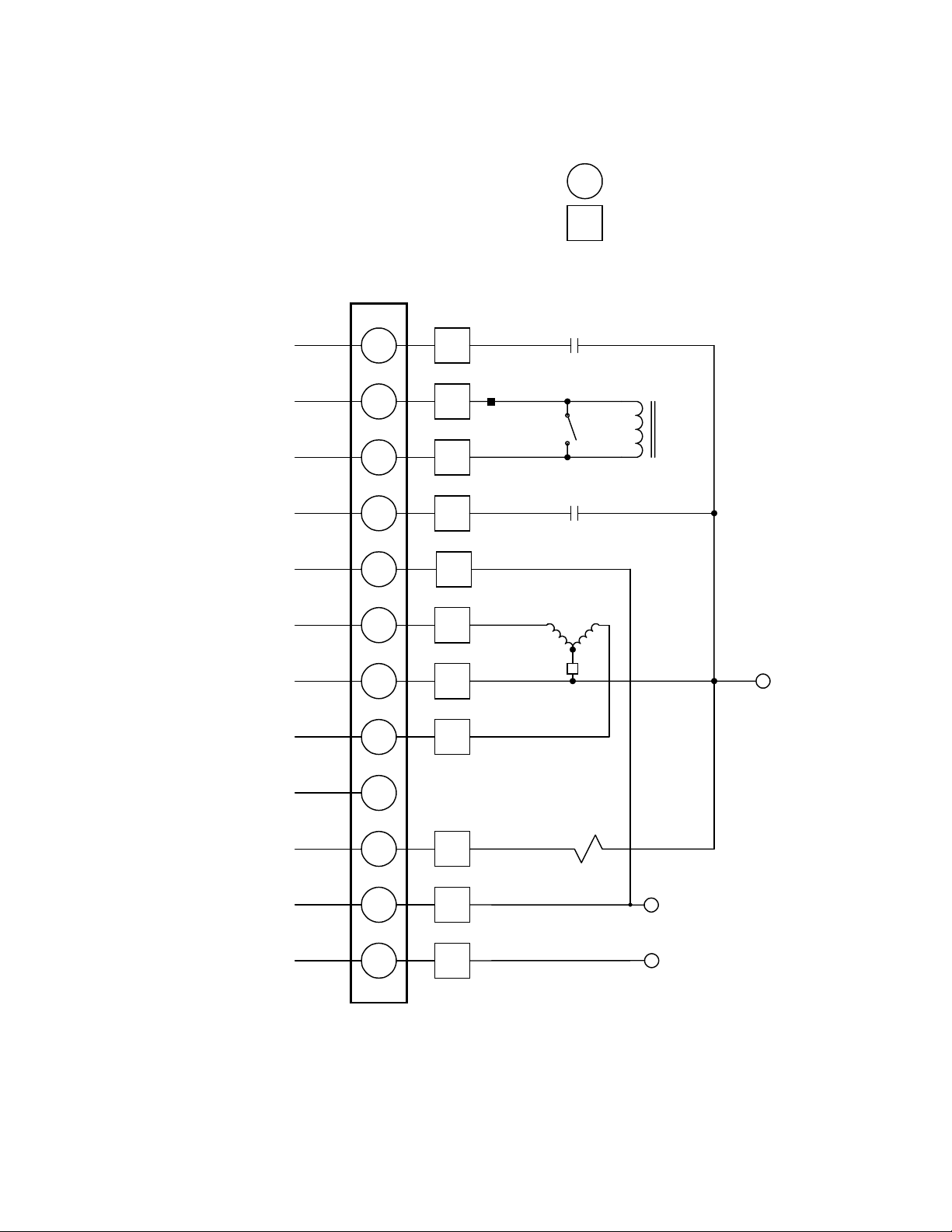
3.5 External Connections
External connections are accomplished via a (12connection) terminal strip located on the rear of
the unit. See Figures 3-4, 3-8, and 3-12, External
Connections, for connection points.
Terminal 1 – Counter Input
This digital input registers the counter contact
closure. The operation count will increment when
terminal 1 is connected to neutral (terminal 7) or
disconnected from neutral through an external dry
contact. The counter is configured through
SLIMcom for X1 level sensing (G.E. regulators)
or X2-edge sensing (Siemens regulators) operation.
See Chapter 7 for details.
Terminal 2 – Load Current Polarity
The line current input range is 0–400 mA with
200 mA representing the nominal 1.0 per unit value.
The measured current value is used for line drop
compensation and metering calculations.
Terminal 3 – Load Current Return
This is the non-polarity input to the load current
measuring transformer. The companion polarity
input is terminal 2. The line current transformer
input is isolated from other terminals.
Terminal 4 – Neutral Position (Neutral)
This is the input to the Neutral side of the Neutral
Contact detection circuit. It is connected to the
Neutral Contact output of the Regulator.
Terminal 5 – Neutral Position (Hot)
This is the input to the Hot side of the Neutral
Contact detection circuit. It is connected to 120 V
ac via the harness.
Terminal 6 – Tapchanger Lower Output
This switched output connects the tapchanger lower
winding or an interposing relay to the source of
motor power. It is capable of switching up to 6 A
at 120/240 V ac.
Terminal 7 – Neutral
This is the return for the voltage input (terminal
9).
Terminal 8 – Tapchanger Raise Output
This switched output connects the tapchanger raise
winding or an interposing relay to the source of
motor power. It is capable of switching up to 6 A
at 120/240 V ac.
Terminal 9 – Motor Hold
This output is used only with Cooper Regulators.
It is left open for Siemens and GE Regulators.
Terminal 10 – Drag Hands Reset
This output is used to activate the Drag Hands
Reset mechanism. It is protected by F4, a 2 A
fuse.
Terminal 11 – Motor Power Input
The source for powering the tapchanger motor or
interposing relay is connected here. It may have
a nominal voltage of 120 or 240 V ac. This input
is protected by F1, a 6 ampere fuse. Direct current may
not
be switched through these contacts.
Terminal 12 – Voltage Input
This input accepts nominal 120 V ac, 60 Hz to
operate the control's power supply and voltage
sensing input. The acceptable voltage range for
proper control operation is from 80–140 V ac. Power consumption is 6 VA or less. The input voltage
is referenced to line neutral (terminal 3). This input is protected by a 0.25 A fuse, F2. The unit
will withstand 1000 V ac hi-pot from neutral to
ground, since it is recommended that the VT neutral
be grounded at only one point.
See Figure 3-4 for typical external connections.
& WARNING: Open CT secondary will result
in high voltage at CT terminals. Death, severe
injury or damage to equipment can occur. Do
not operate with CT secondary open. Short
circuit or apply burden at CT secondary during operation.
■■
■ NOTES:
■■
1. Motor voltage may be 120 or 240 V to neutral
or 240 V phase-to-phase.
2. The customer is to provide earth ground
connection to CT/VT's neutral connection,
external to the control.
3–14
Page 40

4 Applications
4.0 Introduction ............................................................................... 4–1
4.1 Measurements & Calculations ................................................. 4–2
4.2 Voltage Regulation ................................................................... 4–3
4.3 Regulation Limits ...................................................................... 4–5
4.4 Non-Sequential/Blocking .......................................................... 4–5
4.5 Counters .................................................................................... 4–5
Applications – 4
4.6 CT/VT Phase Shift .................................................................... 4–6
4.7 Ratio Multipliers ........................................................................ 4–6
4.8 Tap Position .............................................................................. 4–6
4.0 Introduction
The Autodaptive® Regulator Control (ARC) is a
unique control that relies on Autodaptive-style
algorithms to optimize voltage control while
minimizing the number of tapchange operations
required. This results in reduced tapchanger
maintenance and optimized loading.
VRQF
VRQF (Voltage Regulation Quality Factor) is
defined as the RMS deviation in voltage from a
reference voltage, as averaged over a selected
time period. The reference voltage for Autodaptive
Regulator Controls is the voltage setpoint of the
control. One purpose for the regulator control is
to minimize the VRQF or variation of the supply
voltage on a distribution system.
Use of the VRQF algorithm rather than conventional
voltage setpoint/bandwidth/preset timer results in
more precise distribution voltages with reduced
tap operations. The autodaptive voltage controls
operate with a voltage setpoint and a desired VRQF
setting. The bandwidth is a function of the
tapchanger voltage change per tap, and the timing
is adapted from past voltage (VRQF) history, and
the desired VRQF at the bus.
4–1
Page 41

M-2601/02/03 Instruction Book
For example, with a condition of 5/8% taps (0.75 V)
(therefore 1 V bandwidth setting), if the bus voltage
varies more than 0.5 V (1/2 of bandwidth) from
the voltage setting, the regulator control will begin
timing towards an operation. The accumulating
timer has an operational threshold which is adapted
from the VRQF history and the VRQF setting. If
the history illustrates a VRQF less than the setting
(indicating a relatively stable bus voltage), the
threshold will be increased. This allows the natural
stability of the system to correct the voltage, and
in many cases to avoid the need for a tapchange.
If the history illustrates a VRQF higher than the
setting (indicating a relatively variable bus voltage),
the threshold will be decreased. This allows
tapchanges to occur sooner, and system voltage
variations to be minimized.
VAr Bias
Use of VAr Bias allows the Autodaptive® Regulator
Control (ARC) to coordinate its operation with the
M-2501A Autodaptive Capacitor Control (ACC)
devices on the distribution system in order to
minimize losses, subsequent voltage variations,
and equipment capacity requirements of
transmitting VArs.
The application of both the ARC and the ACCs
on a circuit provides for an interaction between
the devices that provides for faster response in
times of rapidly changing conditions on the
distribution system. This application combination
adds a “substation requirements” aspect to the
feeder requirements control of pole-top capacitor
banks.
For example, with one transformer, six feeders,
and 1200 KVAr pole-top feeder capacitor banks,
if each feeder is correctly compensated to within
400 KVAr, all feeder bank controls would be
operating correctly. However, the transformer would
be transforming 2400 KVAr (six feeders times 400
KVAr) from the transmission system. The ARC
on the transformer would detect this condition and
affect additional line capacitor operation by making
a temporary voltage level setting change. By
effectively delaying a voltage tap change for a
short time, a line capacitor bank control could be
biased into operation by the tapchanger control,
with reduced losses, better voltage profiles, and
fewer tap changes.
4.1 Measurements & Calculations
Voltage Measurements
Normal
The ARC accomplishes waveform sampling by
sampling a 60 Hz signal at a rate of four hundred
and eighty samples per cycle, or two hundred and
forty samples per half-cycle. This measurement
is repeated twenty times per second. Two
conditions terminate the sampling for one halfcycle. They are:
1. The voltage being sampled crosses the
zero value line.
2. 240 voltage samples have been collected.
These samples are correlated with sine table entries
and processed to produce a voltage value. This
voltage is the fundamental component of the
voltage wave.
Bandcenter
In the ARC, Bandcenter is the value of voltage
selected by the customer as the desired value of
voltage for regulation. This value is the center
point for the selected bandwidth.
V
measured
V
measured
is the value of voltage which the control
measures for regulation.
Current Measurements
Line Current
Current is measured by its two components with
respect to the voltage signal, the in-phase or real
component (P) and the 90° or quadrature
component (Q). Values of P run from a positive
maximum to a negative maximum. Values of Q
run from a positive to a negative maximum, with
the negative values indicating a lagging power
factor on the load.
A vector sum of these current components is
displayed as secondary current.
4–2
Page 42

Applications – 4
RAILS AND LIMITS
Lower Voltage Limit
If the value of the regulated voltage is below the
Lower Voltage Limit, the control will not time
towards a lower tapchange.
Upper Voltage Limit
If the value of the regulated voltage exceeds the
Over Voltage Limit, the control will not time towards
a raise tapchange. If the value of the regulated
voltage exceeds the overvoltage limit plus a 2 volt
Deadband, the control will issue a lower command
in one second until the regulated voltage falls, at
minimum, back into the deadband.
Tap Position Limits
The control is programmable to prevent automatic
tapchanges that will allow excursions beyond the
set values of minimum and maximum tap positions.
This function does not have priority over any values
of Voltage Limits programmed into the control.
4.2 Voltage Regulation
Standard Control Settings
With the Level 1 password implemented, the
following setpoints are adjustable: BandCenter,
Line Drop Compensation, Upper Voltage Limit,
Lower Voltage Limit, and VRQF. The History
sample period is also adjustable. Alarm Enables
and Resets are settable, and VAr management
can be enabled or disabled. See Table 4-1 for
the ranges. All other setpoints and configuration
choices require level 2 password clearance.
The control will send commands to the tapchanger
to change taps as needed to hold the voltage within
the bandwidth setting, as modified by the line drop
compensation settings.
The control will only respond to an out-of-band
voltage excursion after the timer has reached the
Autodaptive
®
time delay which is set by the
algorithms. The algorithm functions as an
integrating timer dependent on the VRQF, which
increments during time out-of-band and decrements
during time in band, but not below zero. The further
the voltage is away from the setpoint, the shorter
the time delay between tapchanges and vice versa.
Bandcenter
The center of the voltage band is adjustable from
90 to 135 V ac in 0.1 volt increments.
Voltage Regulation Without LDC
When the control is only used to regulate the
voltage on the transformer or regulator low-side
bus, the only input required is voltage from a lineto-line or line-to-ground VT with a nominal 120 V
ac secondary.
Voltage Regulation with LDC
When it is desirable to regulate the voltage at
some distance from the transformer or voltage
regulator, the Line Drop Compensation (LDC)
feature is used.
The bandcenter function is set the same as if LDC
were not used, and still represents the desired
voltage at the remote location.
Password Applicability
Metering panel and list can be read under all
circumstances.
No Password: Setpoint screen can be read, but
not changed. Config screen cannot be read.
Level 1 Password: Setpoint screen can be read,
but only bandcenter, limits, alarms, LDC, VRQF
and history sampling can be changed. Ratio Corr,
multipliers, CT phasing, counters, and clock cannot
be changed. Config screen cannot be read.
Level 2 Password: All parameters in Setpoint
screen can be changed. Config screen can be
read and changed.
A classical approach can be used to determine
the settings for the LDC, however this assumes
a load center point and is usually not applicable
to the typical distribution feeder. For more
information, contact Beckwith Electric for
Application Note #17.
A simpler method is recommended which will work
for most applications. This involves analyzing the
feeders leaving the station and estimating the
reactance/resistance (X/R) ratio. The reactive and
resistive line drop compensation setpoints should
then be entered in this same X/R ratio.
4–3
Page 43

M-2601/02/03 Instruction Book
retnecdnaBV0.531ot0.09V1.0V0.021
FQRVV0.2ot4.0V1.0V6.0
ecnatsiseRCDLV42+ot42-V1V0
ecnatcaeRCDLV42+ot42-V1V0
Table 4-1 Level 1 Password Adjustable Parameters
NOITCNUF EGNARTNIOPTES TNEMERCNI
LAITINI
GNITTES
If the CT and VT phasing corrections have been
made, only positive values of R and X
compensation need to be used.
Table 4-2, Approximate Ratio of Line Reactance
to Resistance (X/R) of Typical Distribution Circuits,
gives the X/R ratio for various wire sizes.
By knowing the ratio of the maximum expected
load to the present load, the amount of voltage
compensation needed is found as shown in the
following example.
Example:
Desired: local voltage @ min load=120 volts
local voltage @ max load=124 volts
Using the following assumptions:
Desired Bandcenter = 120 volts
Desired Bandwidth = 1 volt
The device being controlled is 50%
loaded
Setting
Start with R=0 and X=0, and increase both values
using the ratio shown in the table for the feeder
conductor. Keeping the X/R ratio, increase R
and X
until tapchanger raises the voltage by
set
set
two volts (50% of the desired voltage rise at full
load).
With this simplified method of LDC setting, the
first customer’s voltage will be limited by the upper
voltage limit at the highest daily load, depending
on the accuracy of the daily load projection. At
the same time, the furthest customer will receive
the highest voltage possible under the line and
loading conditions. The first customer protection
can be set on the control. Refer to Section 4.3,
Regulation Limits.
RSCA REPPOC
MCMR/XMCMR/X
5970.40570.6
7745.20055.4
6330.20533.3
6625.10524.2
GWAR/XGWAR/X
0/42.10/40.2
0/20.10/25.1
25.027.0
62.063.0
Table 4-2 Approximate Ratio of Line
Reactance to Resistance
(X/R) of Typical
Distribution Circuits
4–4
Page 44

Applications – 4
Since the daily load projections will likely have a
seasonal variation, the best balance of first
customer to furthest customer voltage may require
seasonal adjustment of the LDC settings. Note
that the settings of R and X compensation are
proportional to the peak load projection and that
new settings can be scaled from the first setting
obtained by the experimental process just
described.
4.3 Regulation Limits
Upper Voltage Limit
A setpoint is available to establish a block raise
limit. The overvoltage limit is adjustable from 90.0 V
to 136.0 V. This limit is equivalent to a First
Customer Protector to limit overvoltage from line
drop compensation action during heavy loading.
If the voltage exceeds the upper voltage limit plus
the 2 V deadband, the control will immediately
call for an “automatic” lower without any time delay.
The upper voltage limit block can be effectively
disabled by setting it to 136 V.
Lower Voltage Limit
This limit is adjustable from 89.0 V to 135.0 V in
1.0 V increments. This limit can be set to limit
low customer voltage to safe limits and will block
voltage reduction action that could cause motor
stalling and other undesirable low voltage effects.
Lower Voltage Limit can be effectively disabled
by setting it to 89 volts. If the voltage is below the
Lower Voltage Limit setpoint, the control will not
issue further lower commands.
Tap Position Limits
This provides for the settings of upper and lower
tap positions beyond which the control is blocked.
Note that these settings can interact with the over
and under voltage limits. Refer to Section 4.8, Tap
Position.
The tap change output is initiated after the
Autodaptive
®
integrating timer has timed out. The
waiting time between the tap changes is adaptive,
subject to a minimum value as set by the Intertap
Minimum Delay.
4.5 Counters
Operations Counter
Two counters, resettable and presettable, are
available on the Autodaptive Regulator Control.
Both counters accommodate numbers up to
999,999, and will record from either an X1 or X2
operations counter output, settable in SLIMcom™.
The resettable counter is reset to zero by command,
and does not retain the value prior to reset.
The presettable counter can be preset from zero
to 999,999 by command, and does
not
retain the
preset value after operations counts are received.
Counters are not affected by a loss of power to
the control.
4.6 CT/VT Phase Shift
With the CT and VT signals in-phase for unity
power flow to the load, the control will properly
calculate line drop compensation. In the majority
of regulator operations, the CT and VT are inphase. If an application arises where the CT and
VT are not in phase, the phase shift can be
corrected through software. The characteristics
of three phase systems only allow multiples of
30° phase shifts. The control, therefore, has a
range of 0° to 330° in 30° increments.
When two single-phase regulators are connected
in open delta, the current signals will be out-ofphase with the voltage signals. For one regulator,
the current will lead the voltage by 30° and is
called the “leading” regulator. For the “lagging”
regulator, the current will lag the voltage by 30°.
4.4 Non-Sequential/Blocking
The control operates in non-sequential mode. The
control will make one tapchange and then timeout
once more before making another. This is
accomplished by energizing an Output until a
counter contact input is received.
4–5
Page 45

M-2601/02/03 Instruction Book
4.7 Ratio Multipliers
VT User Correction Voltage
This feature is included to permit VOLTAGE
TRANSFORMER ratio correction. It permits the
measured voltage to be adjusted over a K12 V
ac range to compensate for voltage transformer
ratios that would yield an improper representation
of customer voltage.
CT User Correction Multiplier
This feature is included to permit CURRENT
TRANSFORMER ratio correction. It permits the
measured voltage to be adjusted over a 50 to
200% range to compensate for current transformer
ratios that would yield an improper representation
of customer voltage.
Primary Voltage and Current Multipliers
Primary quantities are displayed when voltage and
current multipliers are set into the control. The
voltage multiplier is: V
(V
)(V
sec
)). For example: If the VT ratio is
corr
mult
= V
pri
/(V
sec
+
7620/120 = 63.5 and the correction multiplier is
+5.8%, the ratio of the voltage multiplier is 60.
The current multiplier is the value of the line CT
primary rating divided by 0.2 A.
For a CT primary rating of 1000 A, the multiplier
is:
CT
= 1000/0.2 = 5000
mult
The current multiplier setting range is
from 20 to 25,000 in increments of 1.
4.8 Tap Position
The Autodaptive® Regulator Control applies to
tapchanger designs with a lowest tap position
configuration of –16 to a highest tap position
configuration of +16.
Tap Position by Keep Track
This feature allows the control to keep track of
the presently operating tap.
It is recommended that the indicated tap position
be compared to the mechanical tap position
indicator at regular intervals, and that the indicated
value be corrected, if necessary.
The user initializes the control at a given, known,
tap position upon installation by performing the
following steps:
1. Determine the actual tap position from the
external tap position indicator on the
regulator.
2. Using the SLIMcom™ communications
program, calibrate the tap position by
entering the current tap value under "tap
position". The tap position is now calibrated
to recognize all subsequent operations so
as to “keep-track” of the present tap
position.
3. The present tap position is indicated in
the Tap Position screen.
The keep-track procedure recognizes tapchanges
commanded via:
• The control software.
• The panel switches.
• External contacts.
4–6
The tap position stored in memory is not affected
by a loss of supply power.
Page 46

5 Communications
5.0 Introduction ............................................................................... 5–1
Status – 5
5.0 Introduction
Currently, there is only one available method of
communication to the Autodaptive® Regulator
Control, through the front panel RS-232 serial
COMM port, using the Beckwith M-2802 SLIMcom
Communications program. This proprietary protocol
is compatible with Microsoft® Windows 95/98, and
establishes a link using COMM ports available
on-board with most popular computers.
The RS-232 COMM port is optically isolated to
assure no compromise of the voltage isolation integrity of the device.
™
5–1
Page 47

M-2601/02/03 Instruction Book
This Page Intentionally Left Blank
5–2
Page 48

Test Procedure –6
6 Field Operation Verification
6.0 Bench Test .................................................................................6–1
6.1 Post-Installation Test................................................................. 6–4
Disclaimer
The purpose of this procedure is to verify
the basic functionality of the Autodaptive
Regulator Control (ARC). Considering the
inherent Autodaptive characteristics of the
regulator control, such as cumulative behavior
of operating variables, the reproducibility of
some variables may be limited. For additional
information regarding testing of the ARC,
please contact Beckwith Electric Company.
Refer to Chapter 7, M-2802 SLIMcom™ for
SLIMcom operating instructions.
■■
■ NOTE: This procedure is to be performed
■■
by qualified personnel who are familiar with
the safe operation of test equipment in
substation environments.
6.0 Bench Test
Equipment needed:
• Variable voltage and current source
• 90-145 V ac, 60 Hz
• 0-200 mA, 60 Hz phase locked to
voltage source. Phase angle adjustable from 0 to +180°
• High impedance true RMS voltmeter
with accuracy of ±0.2% or better
• AC current meter with accuracy of ±1%
or better
• Two 120 V ac indicator lamps
®
• PC with SLIMcom software and RS-232
cable
Procedure:
1. Connect the equipment as shown in
Figure 6-1.
2. Apply 120 V ac and verify that the
green OK LED is blinking.
3. Using SLIMcom, check that the
displayed secondary voltage is 120 V
ac ±0.3% with the same voltage applied
to the control.
4. Apply 100.0 mA 0° confirm that the
displayed secondary current is 100.0
mA ±2.0%.
5. Remove the current applied in step 4.
6. Bandcenter check:
a. Set the voltage bandcenter to 120 V.
b. Slowly raise the input voltage until
the green LOWER LED lights.
Record the voltage at which the
LED first lights.
c. Slowly lower the input voltage un-
til the green RAISE LED lights.
d. Record the voltage at which the
LED first lights.
e. The bandcenter should be the mid-
way point between these two voltages.
7. Return the input voltage to 120 V ac.
6–1
Page 49
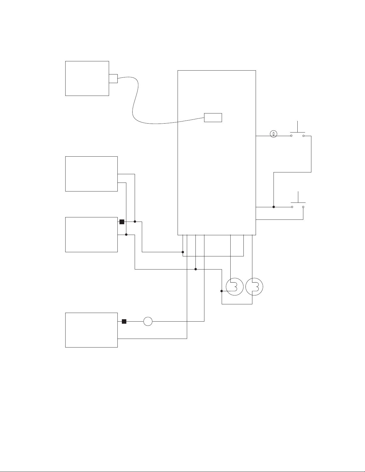
M-2601/02/03 Instruction Book
PC
RS-232 Cable
Voltmeter
Voltage Source
M-2601/02/03
12
372
RS-232
Light Bulb
60 W or
Greater
9
7
1
11
8
6
Current
Sense
Switch
Counter
Test
Switch
Current Source
6–2
"R"
"L"
I
Figure 6-1 External Connections for Test Procedure
Page 50

Test Procedure –6
8. Raise the input voltage until the red
LOWER LED lights. Observe that the
lower relay picks up and lights the
LOWER indicator lamp in one minute
or less.
9. Lower the input voltage until the red
RAISE LED lights. Observe that the
raise relay picks up and lights the
RAISE indicator lamp in one minute or
less.
10. Resistive LDC check:
a. Apply a current of 200 mA 0° to
the Line Current Input.
b. Set the Resistive LDC to +12 V.
c. Verify that the raise relay closes,
causing the RAISE indicator lamp
to light.
d. Raise the input to above 132 V
ac, and verify that the RAISE indi-
cator lamp extinguishes, and the
control RAISE LEDs are extin-
guished.
e. Set the resistive LDC to –12 V.
f. Verify that the lower relay closes,
causing the LOWER indicator lamp
to light.
g. Lower the input to below 108 V
ac, and verify that the LOWER in-
dicator lamp extinguishes, and that
the control LOWER LEDs are ex-
tinguished.
h. Set the Resistive LDC to 0 V.
11. Reactive LDC Check:
a. Apply a current of 200 mA 90° to
the LDC current input.
b. Set the reactive LDC to +12 V.
c. Verify that the raise relay closes,
causing the RAISE indicator lamp
to light.
d. Raise the input to above 132 V
ac, and verify that the RAISE indi-
cator lamp extinguishes, and the
control RAISE LEDs are extin-
guished.
e. Set the reactive LDC to –12 V.
f. Verify that the lower relay closes,
causing the LOWER indicator lamp
to light.
g. Lower the input to below 108 V
ac, and verify that the LOWER indicator lamp extinguishes, and that
the control LOWER LEDs are extinguished.
12. Counter Check (2601, 2602):
a. Adjust input voltage until the unit
initiates a Raise or Lower.
b. Press the button connected to the
counter input.
c. Using SLIMcom™, confirm that the
presettable and resettable counter
values increment when the button
is pressed.
13. Current Sense Check (2603):
a. Adjust input voltage until the unit
initiates a Raise or Lower.
b. Push the current sense switch.
c. Raise or Lower relay should be
dropped.
d. Using SLIMcom™, confirm that the
presettable and resettable counter
values increment when the button
is pressed.
14. Upper/Lower Blocking Check:
a. Apply a current of 200mA 0° to
the Line Current Input.
b. Set the resistive LDC to +24 V.
c. Set the Upper Voltage Limit to
132 V.
d. Verify that the red RAISE LED is
on.
e. Slowly raise the input voltage until
the RAISE LED extinguishes.
f. Confirm that this occurs at 132.00 V
K0.3%.
g. Apply a current of 200 mA 180°
to the LDC current input.
h. Set the resistive LDC to –24 V.
i. Set the Lower Voltage Limit to
108 V.
j. Verify that the red LOWER LED
lights.
k. Slowly lower the input voltage un-
til the LOWER LED extinguishes.
l. Confirm that this happens at 108 V
K0.3%.
6–3
Page 51

M-2601/02/03 Instruction Book
6.1 Post-Installation Test
1. Install control as described in Section
3.0, Installation.
2. Place the AUTO/MANUAL switch in
the MANUAL position.
3. Manually raise the tap until the RED
LOWER LED on the control lights.
4. Place the AUTO/MANUAL switch of
the test unit in the AUTO position.
5. Verify that the unit issues at least one
lower command in one minute or less.
Subsequent operations may require an
extended time period.
6. Place the AUTO/MANUAL switch in
the MANUAL position.
7. Manually lower the tap until the RED
RAISE LED on the control lights.
8. Place the AUTO/MANUAL switch in
the AUTO position.
9. Verify that the unit issues at least one
Raise command in one minute or less.
Subsequent operations may require an
extended time period.
6–4
Page 52

M-2802 SLIMcom – 7
7.0 Introduction ............................................................................... 7–1
7.1 Installation and Setup ............................................................... 7–1
7.2 Description ................................................................................ 7–3
7.0 Introduction
7 SLIMcom™
1
3
The M-2802 SLIMcom Communication Software
program is designed to provide communication
for setting up, monitoring, and downloading history from the Autodaptive® Regulator Control
(ARC).
7.1 Installation and Setup
SLIMcom runs under the Microsoft® Windows 95
or 98 operating system, and is available in the
following IBM PC-compatible format:
• two 3.5" double-sided, high-density (DS/HD
1.44 Mb) disks
Hardware Requirements
SLIMcom will run on any IBM PC-compatible computer that provides at least the following:
• 8 Mb of RAM (Win 95) or 16 Mb (Win 98)
• Windows 95 or Windows 98
• One 3.5" double-sided, high-density
(DS/HD 1.44 Mb) disk drive
• one serial (RS-232) communication port
• VGA monitor (800 x 600 or greater resolu-
tion recommended)
• Mouse or pointing device
• One null-modem 9-pin female to male mo-
dem cable.
• One Autodaptive Regulator Control.
A
B
C
7–1
Page 53
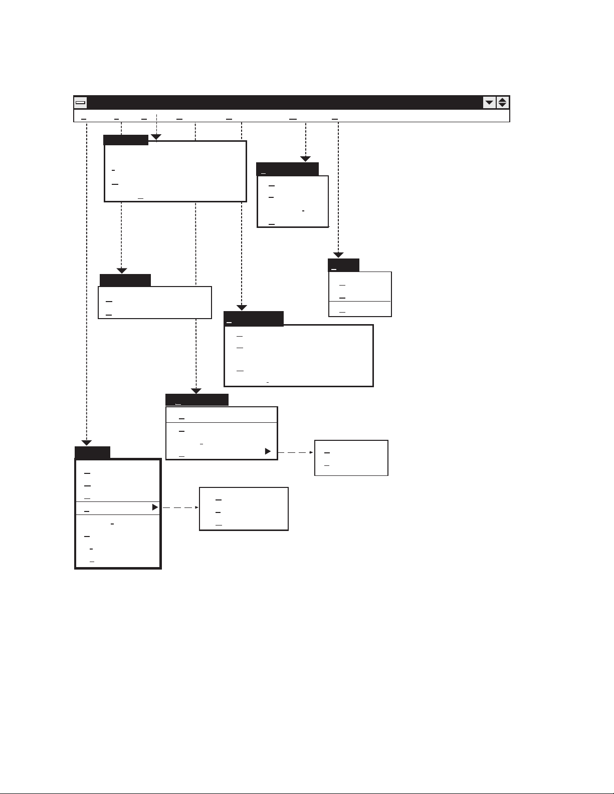
M-2601/02/03 Instruction Book
SLIMComf (M-2802 Communications)
File
Setup HelpWindow
Security
Commands
Retrieve Data
1
3
A
B
Security
Unit Address Alt + a
Information Alt + i
Change Passwords Ctrl + c
Enter
Passwords Alt + p
Setup
Open Comm Ctl + p
Close Comm Alt + c
File
New
Open
Close
Load Data
review
Print P
Print
rint Setup
P
xit
E
Retrieve Data
History Data Alt + h
Outage Data Alt + o
Tap Statistics A + t
Metering Data Alt + m
M-2501
C
ommands
Setpoints Ctrl+s
Voltage Bias Ctrl+v
tions Ctrl+t
Selec
Erase Control
History
Tap Statistics
Outage
Window
Cascade
Tile
Arrange
Close All
Import Alt + i
Icons
Help
Contents
Using Help
About...
History
Tap Statistics
C
Figure 7-1 SLIMcom Main Menu Flow
■ NOTE: Greyed-out commands denote functions which are unavailable at this time.
7–2
Page 54
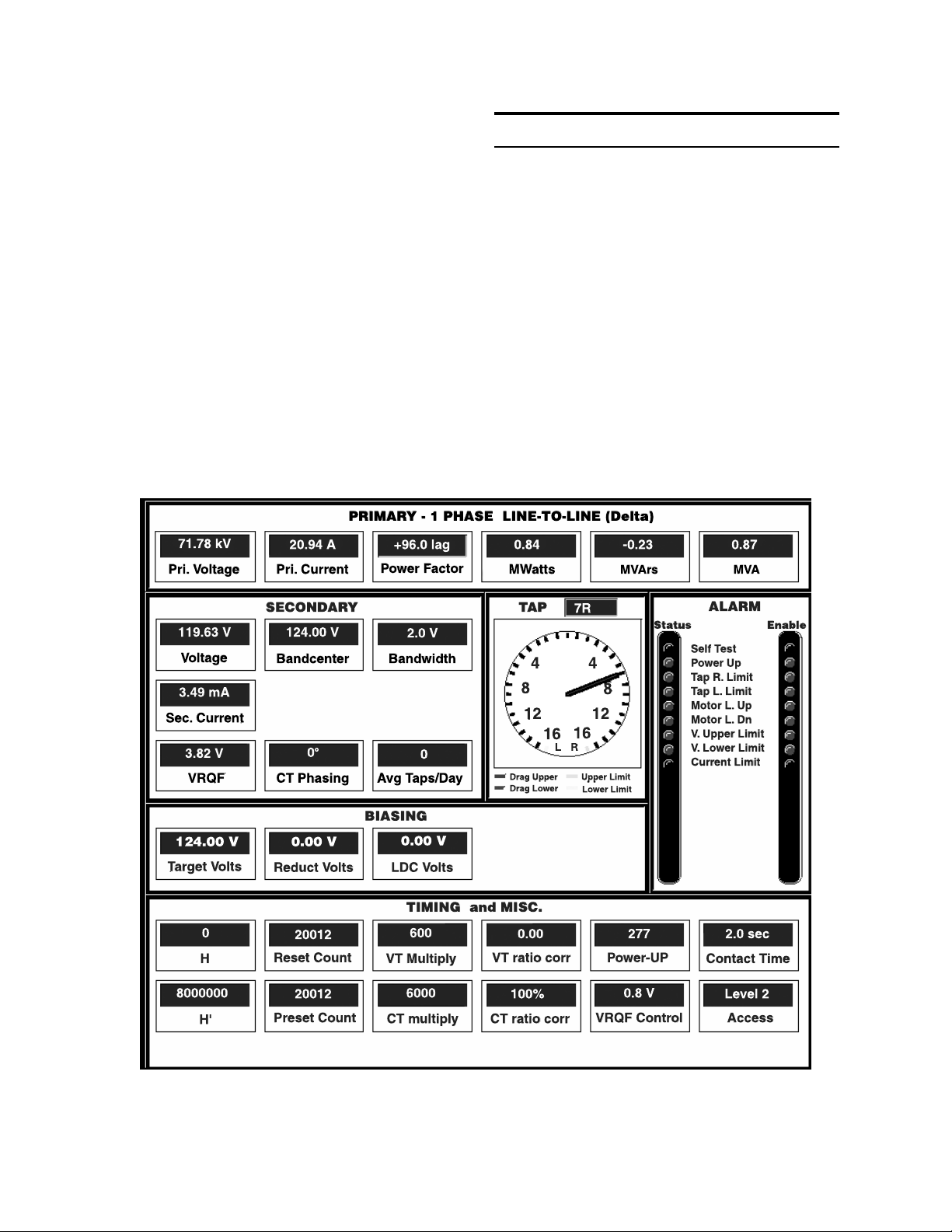
M-2802 SLIMcom – 7
Installation
An installation utility has been provided as a part
of SLIMcom™. After installation, the program can
be run from the hard drive by choosing the SLIMcom icon from the Start menu.
System Setup
Connect a null-modem cable from the COMM
port of the control to the PC serial port.
7.2 Description
This section describes each SLIMcom menu
selection and explains the commands in the same
order as they are displayed in the software
program.
When SLIMcom is run, a Metering Status screen
is displayed (see Figure 7-2, below).
■ NOTE: If no control is attached to the PC, then
zero values will appear on the Metering Status
screen.
1
3
Figure 7-2 Metering Status Screen
A
B
C
7–3
Page 55
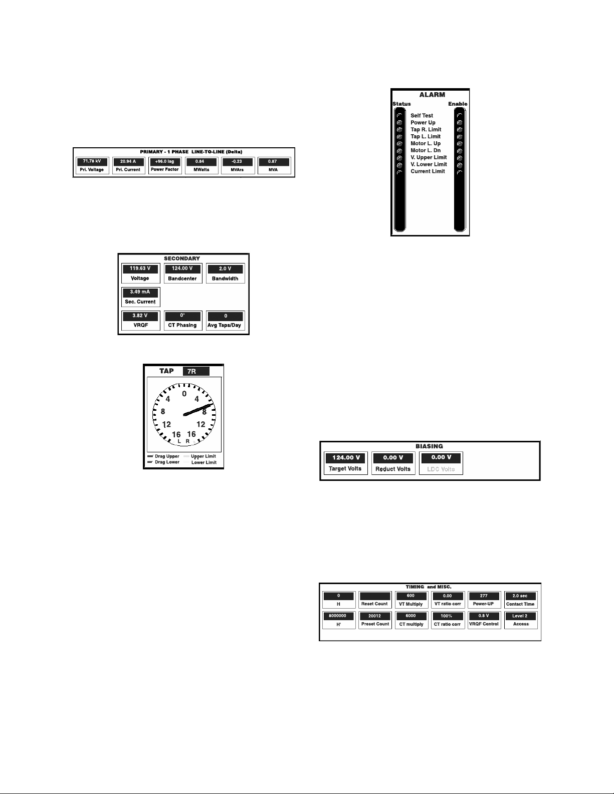
M-2601/02/03 Instruction Book
1
3
PRIMARY Status
The Primary Status display bar shows the primary
quantities calculated, based on secondary values
of the load tap changer, and appropriate
multipliers.
SECONDARY Status
The Secondary Status display box shows the
quantities calculated at the end of the ARC connection point.
TAP Position Clock
ALARM LED Indicators
The Metering Status screen (see Figure 7-2),
contains an array of Alarm LEDs that illuminate
to indicate a specific Tap Changer Control
condition.
Status LED column identifies and indicates (when
lit) the condition of an alarm, if enabled.
Enable LED column indicates whether or not a
particular alarm is tracked.
A
B
C
TAP Indicators
The black pointer indicates actual tap position.
Drag Upper (red) dial hand: Records the highest tap position. The dial hand remains fixed at
the highest tap position until reset.
Drag Lower (green) dial hand: Records the lowest
tap position until reset.
Upper Limit (blue): Indicates the highest tap
position indication permitted.
Lower Limit (yellow): Indicates the lowest tap
position indication permitted.
BIASING Display Bar
The Biasing display bar displays the amount of
voltage that is added or subtracted from the
voltage bandcenter.
TIMING and MISC Display Bar
The Timing and MISC (miscellaneous) display
bar includes timing parameters to perform “raise”
and “lower” tap change positions. The display
bar also includes miscellaneous counter reset
and presets.
7–4
Page 56
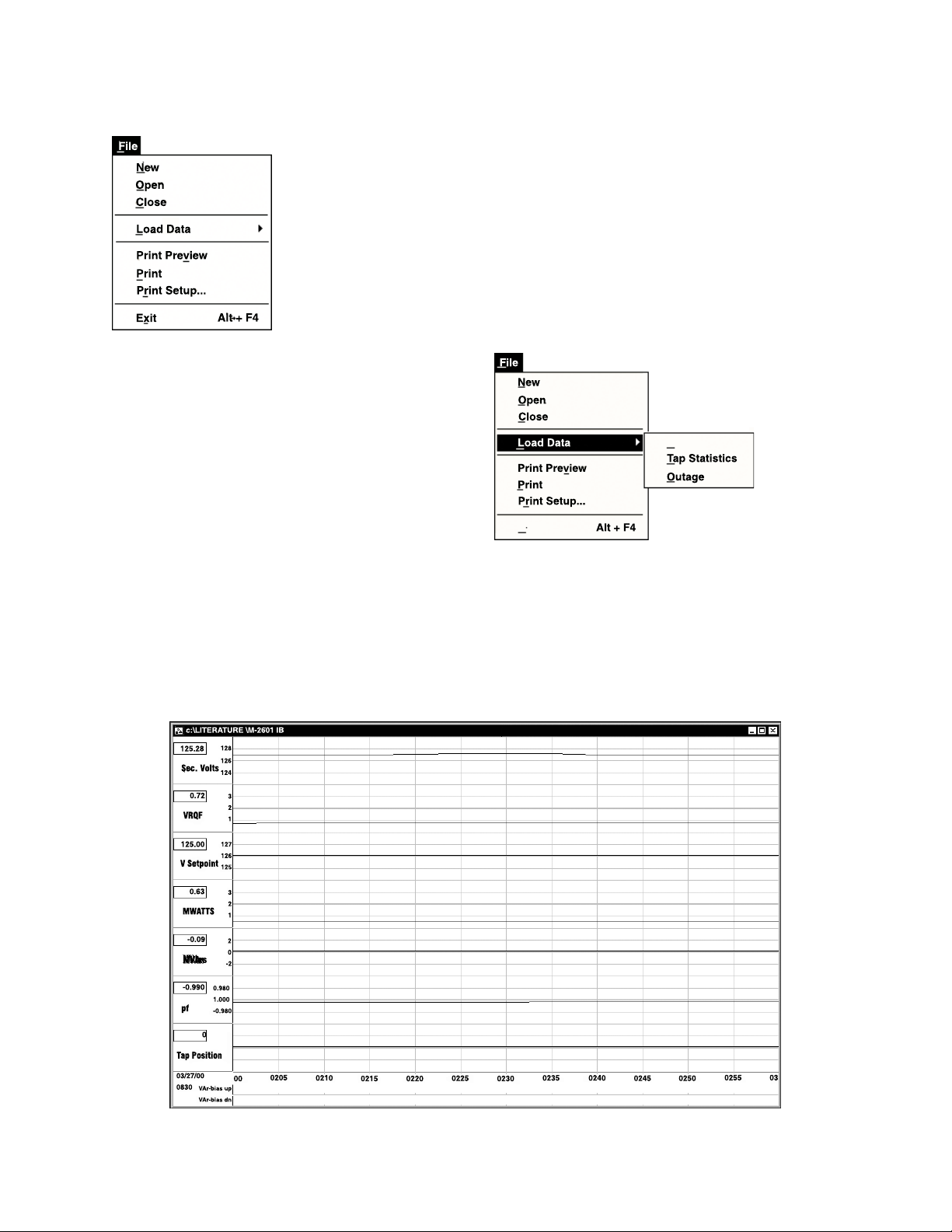
M-2802 SLIMcom – 7
File Menu
The File menu enables the user to create a New
Setpoint file, and Open a previously created
Setpoint file.
New – A new file is established with the
Setpoints dialog box (see Figure 7-4). This
feature is currently unavailable, and will appear
greyed-out in display.
■■
■ NOTE: By choosing the New command, unit
■■
and setpoint configuration values are based on
factory settings specified.
Print Preview – Allows previewing of the Sta-
tus/Metering/Graphing screens before sending the
data to the printer. Only available when downloaded data is viewed.
Print Setup – Allows the user to select printer
options such as landscape or portrait orientation.
Only available when downloaded data is viewed.
Print – Allows printing of the top-most window
selected. Only available when downloaded data
is viewed.
Exit – The Exit command quits the SLIMcom™
program, and automatically closes the
communication port used.
Load Data submenu
The Load Data submenu presents three
commands: History, Tap Statistics, and Outage.
The first three commands will each display history
graphs of the selected data. Each of these screens
may be previewed and printed. The data screens
that may be loaded are as shown in Figures 7-3,
7-4, and 7-5.
1
3
A
Figure 7-3 History Data Screen
B
C
7–5
Page 57
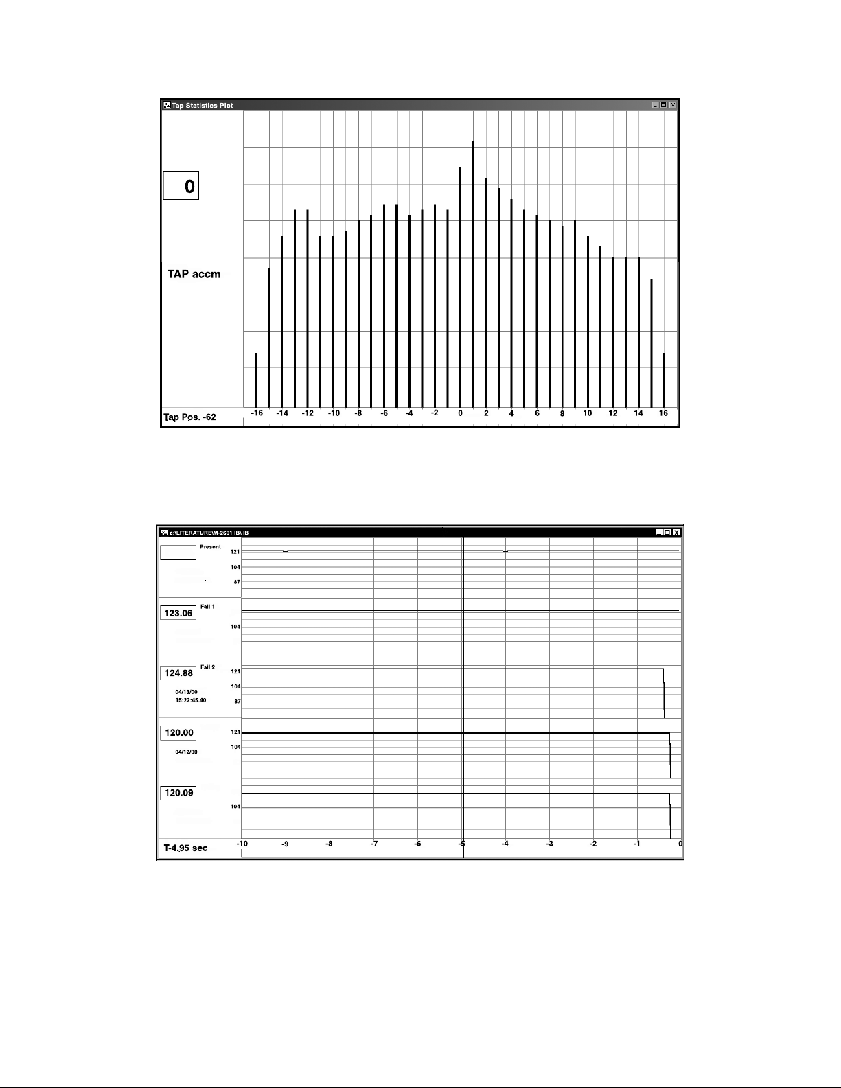
1
M-2601/02/03 Instruction Book
3
A
B
Figure 7-4 Tap Statistics Screen
C
Figure 7-5 Outage Screen
7–6
Page 58
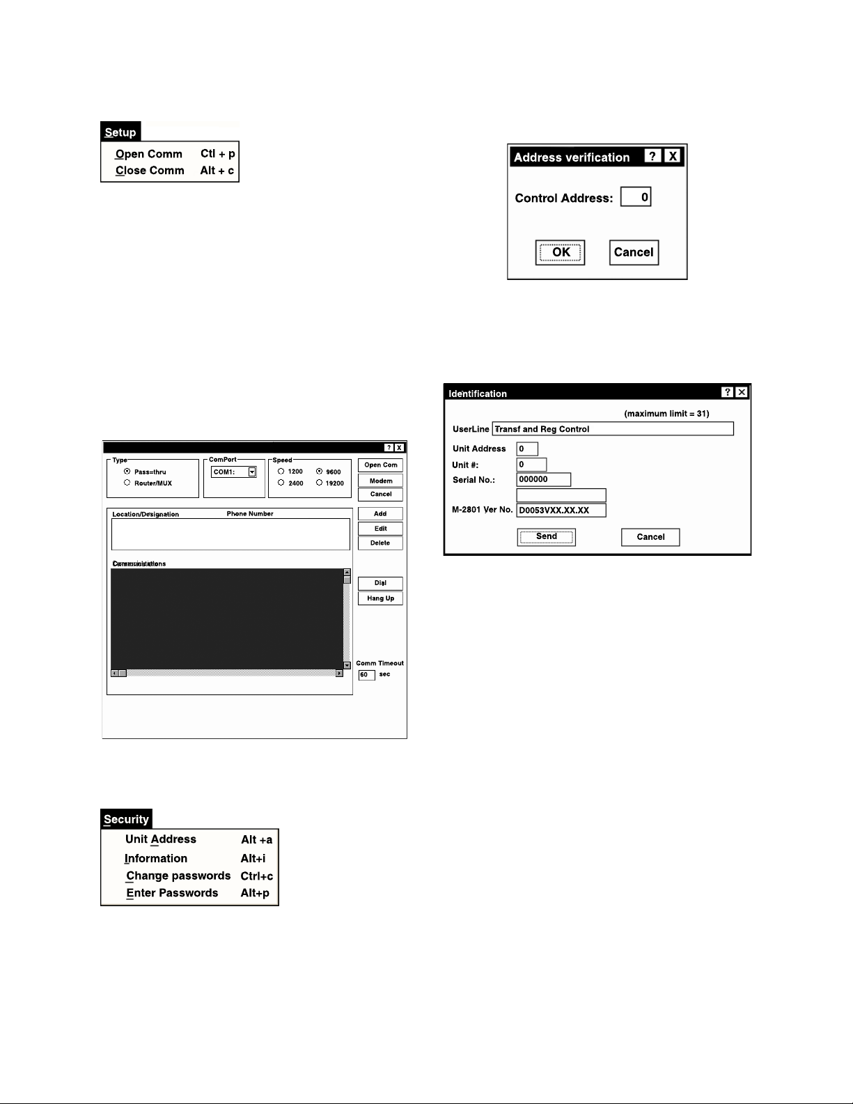
M-2802 SLIMcom – 7
Setup Menu
The Setup menu provides two commands: Open
COMM and Close COMM.
The Open COMM displays a communications
screen (see Figure 7-6) to select the appropriate information regarding the system on which
the controller is operating.
Modem baud rate is fixed at 9600 baud. Other
rates are greyed-out and currently unavailable.
The Pass-Thru and Router/MUX selections are
also currently unavailable, and will appear greyedout in display.
Selection of the Unit Address command
1
Selection of the Information command displays
an Identification dialog screen (see Figure 7-7),
which allows the user to enter specific CT and
controller identification data.
3
Figure 7-6 Setup Communications Screen
Security Menu
The Security menu provides four commands: Unit
Address, Information, Change Passwords and
Enter Passwords.
Figure 7-7 Identification Dialog
The Identification dialog box reflects the following:
User Line – A 31-character description which
identifies the location of the Load TapChanger
(LTC).
Unit Address – An integer from 0 to 127; 0
disables.
■ NOTE: In multiple control installations, set unit
address prior to connecting to communication multiplexing equipment.
Transformer Number – Contains the descrip-
tion of the transformer (LTC) number (an integer
from 0 to 65,535).
Serial Number – Contains Beckwith’s assigned
unit serial number.
M-2601/02/03 Ver. No. – Contains assigned
Beckwith version number for Regulator Control.
M-2802 Ver. No. – Contains assigned Beckwith
version number for SLIMcom™.
A
B
C
7–7
Page 59
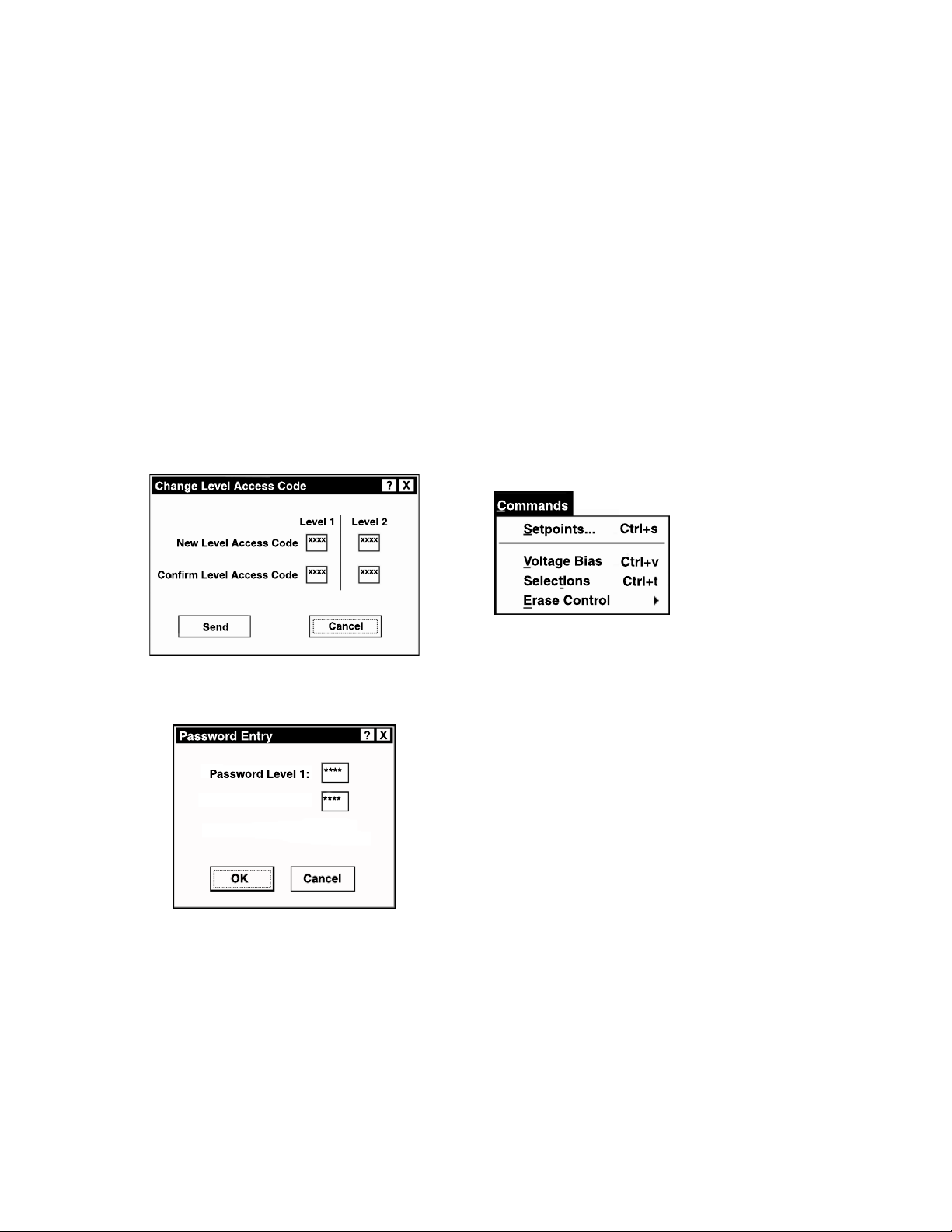
M-2601/02/03 Instruction Book
1
3
Send – Sends the currently displayed informa-
tion to the control.
Cancel – Returns user to the SLIMcom main
window. Any changes to the displayed information are lost.
Change Passwords Command
When the Change Passwords command is selected, a Change Level Access Code dialog box
(see Figure 7-8) is displayed. The access codes
in this menu are all four-digit decimal (0–9) combinations. If the correct password is entered, then
the corresponding level is achieved. If the user
is at level 2 or higher, then the “change password” will permit passwords to be changed. The
New Level Access Code and the Confirm Level
Access Code must be the same.
When the Enter Passwords command is selected,
a Password Entry dialog (see Figure 7-9) is displayed. This menu contains three levels of passwords:
Level 1: Read and write, no password change
allowed. Default is 1111.
Level 2: Read and write, password changes al-
lowed. Default is 2222.
Command Buttons
OK: Sends the appropriate password level to gain
access to the controller.
Cancel: Returns user to the SLIMcom main window. Any changes to the displayed information
are lost.
Commands Menu
A
B
C
Figure 7-8 Change Level Access Code
Password Entry Command
Figure 7-9 Password Entry Submenu
The Commands menu provides three commands
(Setpoints, Voltage Bias, and Selections) and
one submenu (Erase Control) to allow the user
select the necessary control functions. Please
note that Voltage Bias is currently unavailable
and will appear greyed-out in display.
Setpoints Command
Selection of the Setpoints command displays a
Setpoints dialog box (see Figure 7-10) from which
the individual control functions can be selected.
7–8
Page 60
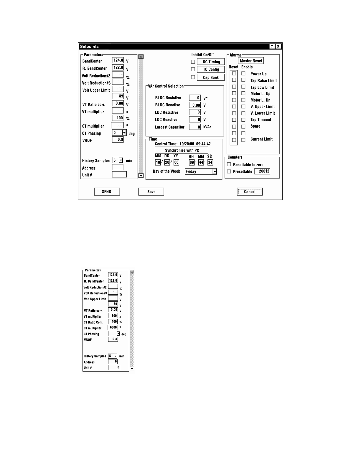
M-2802 SLIMcom – 7
1
Figure 7-10 Setpoints Dialog Box
Parameters
The Parameters dialog allows the user to select
desired voltage values for regulation during initialization of the tap changer control.
Forward power Bandcenter is adjustable from
90.0 V to 135.0 V in 0.1 increments with a factory setting of 120 V.
Two voltage limits, each adjustable from 89 V to
135 V in 1 V increments for the Lower Voltage
Limit, and 90 to 136 V in 1 V increments for the
Upper Voltage Limit. The Volt Upper Limit is
factory set at 132 V. The Volt Lower Limit is
factory set at 108 V.
VT User Corr voltage is adjustable from
–12 V to +12 V in 0.01 increments, with a factory
setting of 0.00 V.
VT Ratio Multiplier adjustable from 20 to 5000
in 1 increments, with a factory setting of 60.
CT User Corr multiplier is adjustable from 50%
to 200% in 1% increments, with a factory setting
of 100%.
CT Multiplier adjustable from 20 to 25,000 in 1
increments with a factory setting of 60.
CT Phasing correction is adjustable from 0° to 330°
in 30° increments with a factory setting of 0°.
VRQF is adjustable from 0.4 V to 2.0 V in 0.1 V
increments.
3
A
B
C
Volt Reduction is currently unavailable, and will
appear greyed-out in display.
History Samples: 5–60 minutes, at 1 minute in-
crements, with a default setting of 5.0 minutes.
7–9
Page 61
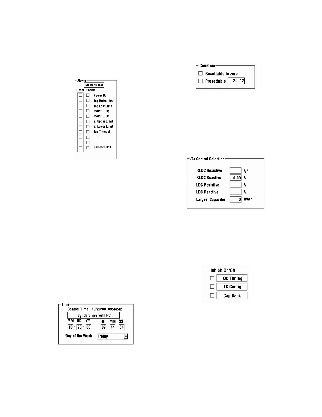
M-2601/02/03 Instruction Book
1
3
Alarms
Alarms are set when the relevant condition is
encountered, and will cause the alarm contacts
to close if enabled. All alarms, once set, remain
thus until deliberately reset.
Master Reset – Reset or toggle all reset check
boxes to enable clearance of all alarms.
Power Up – Alarm is set when power is reapplied to the unit.
Synchronize with PC – Enables the user to set
the control time to match the PC time.
Counters
The Counters screen records the number of ARC
raise and lower operations.
Resettable to zero – Allows the user to reset
the counter to zero.
Presettable – Allows counter to be preset to the
number entered.
VAr Control
A
B
C
Tap High Limit – Alarm is set when the tap po-
sition reaches the tap upper limit.
Tap Low Limit – Alarm is set when the tap po-
sition reaches the tap lower limit.
V. Upper Limit – Alarm is set when the measured voltage is greater than the voltage upper
limit.
Tap Timeout and Current Limit are currently
unavailable and will appear greyed-out in display.
Spaces labeled “Spare” are reserved for future
releases.
V. Lower Limit – Alarm is set when the mea-
sured voltage is less than voltage lower limit.
Time
The Time dialog screen enables the user to review
the internal clocks, prior to entering a new time
setting.
VAr Control allows user to select the largest cap
size for VAr control. This group also allows the
user to select the amount of LDC and RLDC desired. If VAr bias is not required, then the amount
for largest capacitor should be zero (0).
Inhibit On/Off
This provides three dialog buttons; please note
that OC Timing and Cap Bank are currently unavailable and will appear greyed-out in display.
TC Config allows the user to calibrate the control keep-track for initial tap position.
7–10
Page 62
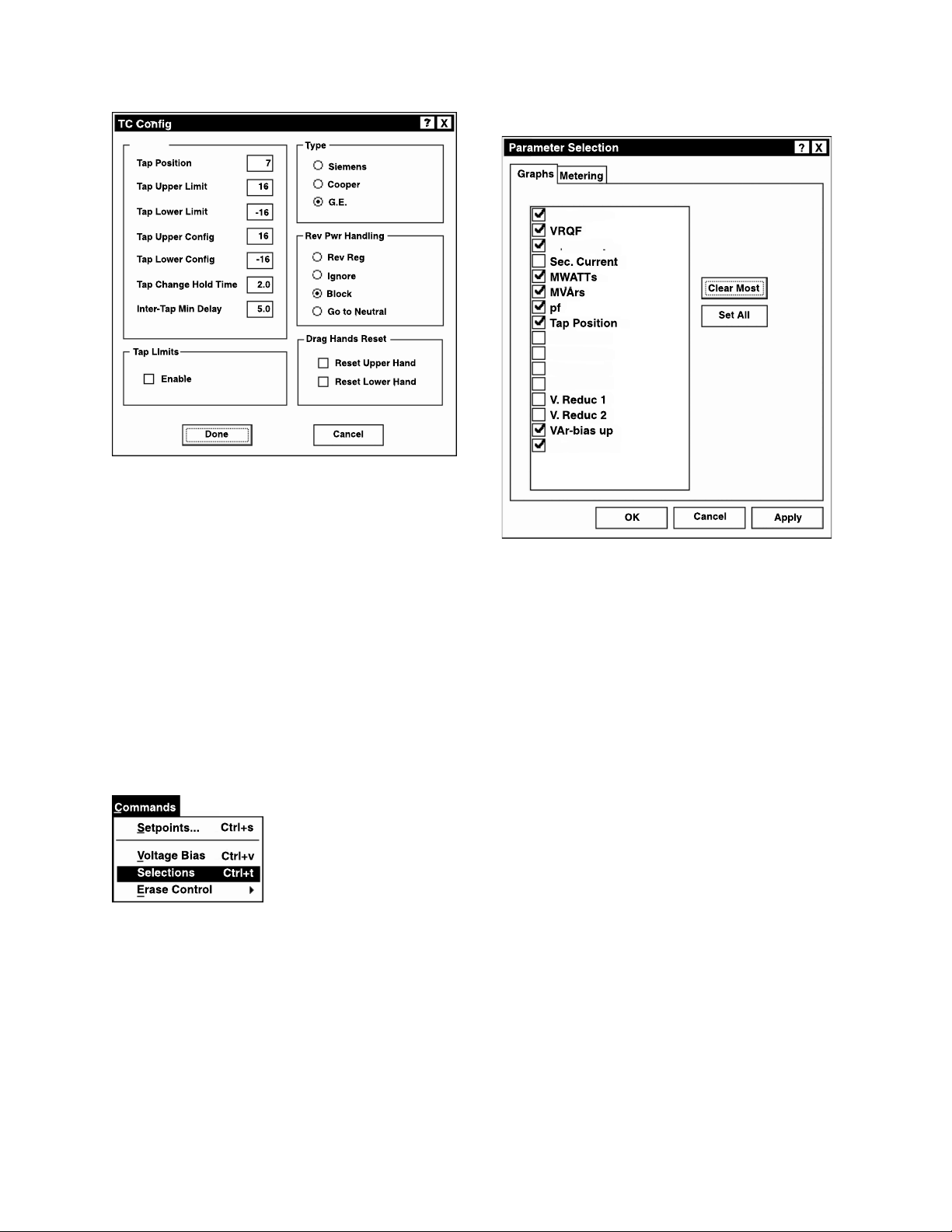
Figure 7-11 Tap Position Setpoints
M-2802 SLIMcom – 7
Graph Selections Table
1
Command Buttons
Send - Sends the currently displayed informa-
tion to the control.
Save - The setpoint information is saved to a
specified file name.
Cancel - Returns the user to the SLIMcom™ main
window. Any changes to the displayed information is lost.
Voltage Bias Command
The Voltage Bias command is currently unavailable and will appear greyed-out in display.
Selections Command
The Selections command enables the user to
select the information that he would require to
view on the screen and printer. The submenu
provides two choices, one for Graphs and the
other for Metering of setpoints.
Figure 7-12 Graph Selections
Command Buttons
Clear Most – Will clear most available parame-
ters for viewing.
Set All – Will check all available parameters for
viewing.
OK – Updates SLIMcom™ with desired selections.
Cancel – Returns user to the SLIMcom main
window.
3
A
B
C
7–11
Page 63
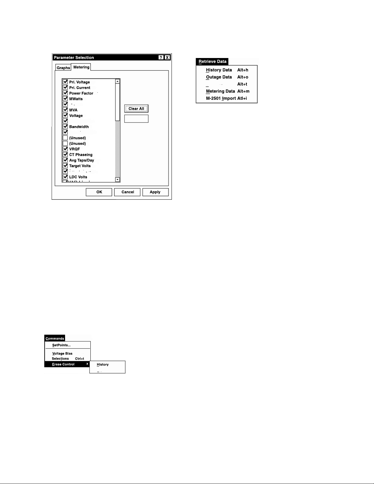
M-2601/02/03 Instruction Book
1
3
A
B
Metering Setpoints Selection Table
Figure 7-13 Metering Selections
Command Buttons:
Clear Selections: Will uncheck all parameters
except voltage because one value, as a minimum, should be displayed.
Set All Selections – Will check all available setpoint parameters for viewing.
OK – Sends the currently displayed information
to the controller.
Cancel – Returns user to the SLIMcom main
window. Any changes to the displayed information are lost.
Erase Control Submenu
Retrieve Data Menu
The Retrieve Data menu provides four com-
mands: History Data, Outage Data, Tap Sta-
tistics, Metering Data, and M-2501 Import.
■ NOTE: These are the only commands which
provide print control.
History Data
If a control is connected to your PC, then any
history data stored in the control is added to the
main history database. If no control is connected, then the main history database is loaded for
viewing. The database is capable of storing
months to years of data at 0 to 60 minutes intervals. Selection of the History Data submenu dis-
plays a history plot of Voltage, VRQF and MWatts
waveforms (see Figure 7-3
Outage Data
The Outage Data command allows retrieval of
five Autodaptive Regulator Control outages, for
a period of 10 seconds each. The outages (see
Figure 7-5), are similar to the waveforms shown
in Figure 7-3.
Tap Statistics
Tap Statistics provides a continuously updated
graph of the taps being made by the control. See
Figure 7-4 for an example of the graphic format.
Metering Data
Metering Data provides a continuous update of
user-selected data quantities (refer to Metering
Setpoints Selection Table).
).
C
The Erase Control submenu allows the user to
erase all data for History or Tap Statistics. This
function erases not only the on-board flash in
the control, but all downloaded data files stored
on your hard drive. To erase current History and
Tap Statistics files from the computer only, use
the Erase Data command from the File menu.
7–12
The Metering Data screen provides an
easy-to-print accounting of all metering data sampled from the control.
Page 64
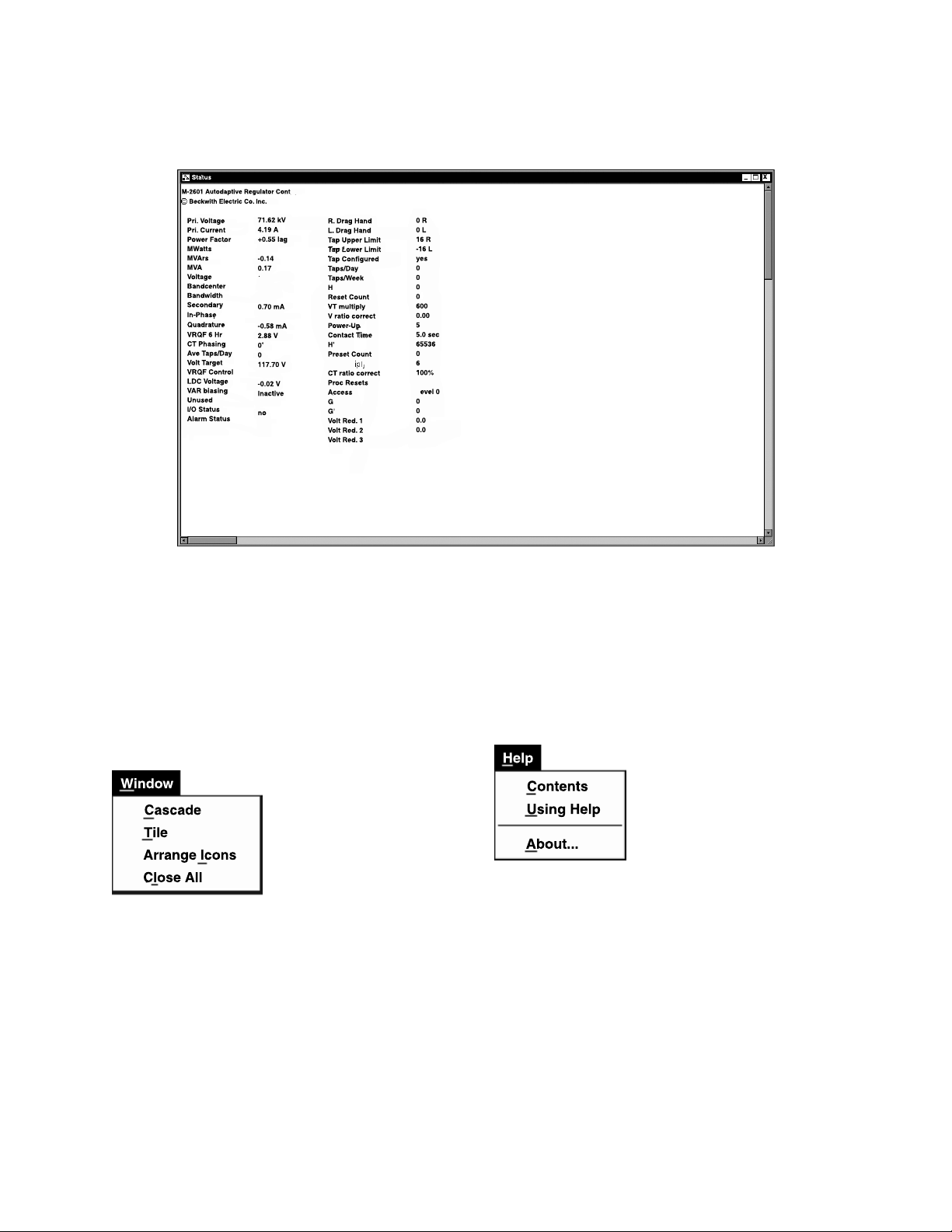
M-2501 Import
This command is currently unavailable and will be greyed-out in display.
M-2802 SLIMcom – 7
1
Figure 7-14 Metering Data
Window Menu
The Window menu contains a group of standard
Windows commands to perform screen arrangements.
3
A
B
The Help menu provides documentation for windows only.
Help Menu
C
7–13
Page 65

1
M-2601/02/03 Instruction Book
3
A
B
This Page Left Intentionally Blank
C
7–14
Page 66

A.0 Null Modem Cable
Appendix A – Communications
A Appendix
Autodaptive Regulator Control
(DB9P)
1
RX
TX
DTR
SGND
DSR
RTS
CTS
unused
2
3
4
5
6
7
8
9
Figure A-1 Null-Modem Cable, 9 pin to 9 pin
PC
(DB9S)
1
2
3
4
5
6
7
8
9
DCD
RX
TX
DTR
SGND
DSR
RTS
CTS
RI
A–1
Page 67

M-2601/02/03 Instruction Book
This Page Left Intentionally Blank
A–2
Page 68

Legal Information
Patent
The units described in this manual are covered by
U.S. Patents 5,315,527, 5,554,064, 5,541,498 and
5,530,338 with other patents pending.
Buyer shall hold harmless and indemnify the Seller,
its directors, officers, agents, and employees from
any and all costs and expense, damage or loss,
resulting from any alleged infringementof United
States Letters Patent or rights accruing thereform or
trademarks, whether federal, state, or common law,
arising from the Seller’s compliance with Buyer’s
designs, specifications, or instructions.
Warranty
Seller hereby warrants that the goods which are the
subject matter of this contract will be manufactured
in a good workmanlike manner and all materials
used herein will be new and reasonably suitable for
the equipment. Seller warrants that if, during a
period of two years from date of shipment of the
equipment, the equipment rendered shall be found
by the Buyer to be faulty or shall fail to peform in
accordance with Seller’s specifications of the
product, Seller shall at his expense correct the
same, provided, however, that Buyers shall ship the
equipment prepaid to Seller’s facility. The Seller’s
responsibility hereunder shall be limited to replacement value of the equipment furnished under this
contract.
Seller makes no warranties expressed or implied
other than those set out above. Seller specifically
excludes the implied warranties of merchantibility
and fitness for a particular purpose. There are no
warranties which extend beyond the description
contained herein. In no event shall Seller be liable for
consequential, exemplary, or punitive damages of
whatever nature.
Any equipment returned for repair must be sent
with transportation charges prepaid. The equipment
must remain the property of the Buyer. The aforementioned warranties are void if the value of the
unit is invoiced to the Seller at the time of return.
Indemnification
The Seller shall not be liable for any property
damages whatsoever or for any loss or damage
arising out of, connected with, or resulting from
this contract, or from the performance or breach
thereof, or from all services covered by or furnished
under this contract.
In no event shall the Seller be liable for special,
incidental, exemplary, or consequential damages,
including but not limited to, loss of profits or
revenue, loss of use of the equipment or any
associated equipment, cost of capital, cost of
purchased power, cost of substitute equipment,
facilities or services, downtime costs, or claims or
damages of customers or employees of the Buyer
for such damages, regardless of whether said claim
or damages is based on contract, warranty, tort
including negligence, or otherwise.
Under no circumstances shall the Seller be liable
for any personal injury whatsoever.
It is agreed that when the equipment furnished
hereunder are to be used or performed in connection with any nuclear installation, facility, or
activity, Seller shall have no liability for any
nuclear damage, personal injury, property damage,
or nuclear contamination to any property located at
or near the site of the nuclear facility. Buyer agrees
to indemnify and hold harmless the Seller against
any and all liability associated therewith whatsoever whether based on contract, tort, or otherwise.
Nuclear installation or facility means any nuclear
reactor and includes the site on which any of the
foregoing is located, all operations conducted on
such site, and all premises used for such operations.
Notice:
Any illustrations and descriptions by Beckwith
Electric Co., Inc. are for the sole purpose of
identification.
The drawings and/or specifications enclosed herein
are the proprietary property of Beckwith Electric
Co., Inc., and are issued in strict confidence;
therefore, shall not be used as a basis of reproduction of the apparatus described therein without
written permission of Beckwith Electric Co., Inc.
No illustration or description contained herein
shall be construed as an express warranty of
affirmation, promise, description, or sample, and
any and all such express warranties are specifically
excluded nor shall such illustration or description
imply a warranty that the product is merchantable
or fit for a particular purpose. There shall be no
warranties which extend beyond those contained in
the Beckwith Electric Co., Inc. terms of sale.
All rights reserved by Beckwith Electric Co., Inc. No reproduction may be made without prior written approval
of the Company.
Page 69

This Page Left Intentionally Blank
Page 70

BECKWITH ELECTRIC CO., INC.
6190 - 118th Avenue North • Largo, Florida 33773-3724 U.S.A.
PHONE (727) 544-2326 • FAX (727) 546-0121
E-MAIL [email protected]
WEB PAGE www.beckwithelectric.com
© 2000 Beckwith Electric Co.
Printed in USA 800-2601/02/03-IB-00 11/00
 Loading...