

Page 1
M-2001D Tapchanger Control Quick Start Guide
Death or severe electrical shock can occur.
WARNING: In no case should the line current circuit be interrupted with the regulator
or transformer energized. Do not remove auxiliary current transformers without
shorting the current inputs.
Exercise care during installation, operation and maintenance procedures
The equipment described in this manual contains voltages high enough to cause serious
injury or death. Only qualied personnel should install, operate, test, and maintain this
equipment. Be sure that all personnel safety procedures are carefully followed. Exercise
due care when operating or servicing alone.
WARNING:
Remove Fuses Before Service.
WARNING: When an adapter panel is not used, automatic shorting of
CT inputs is not provided by the M2001D/M-2050; the customer must
provide a method for shorting the CT's before the control is disconnected.
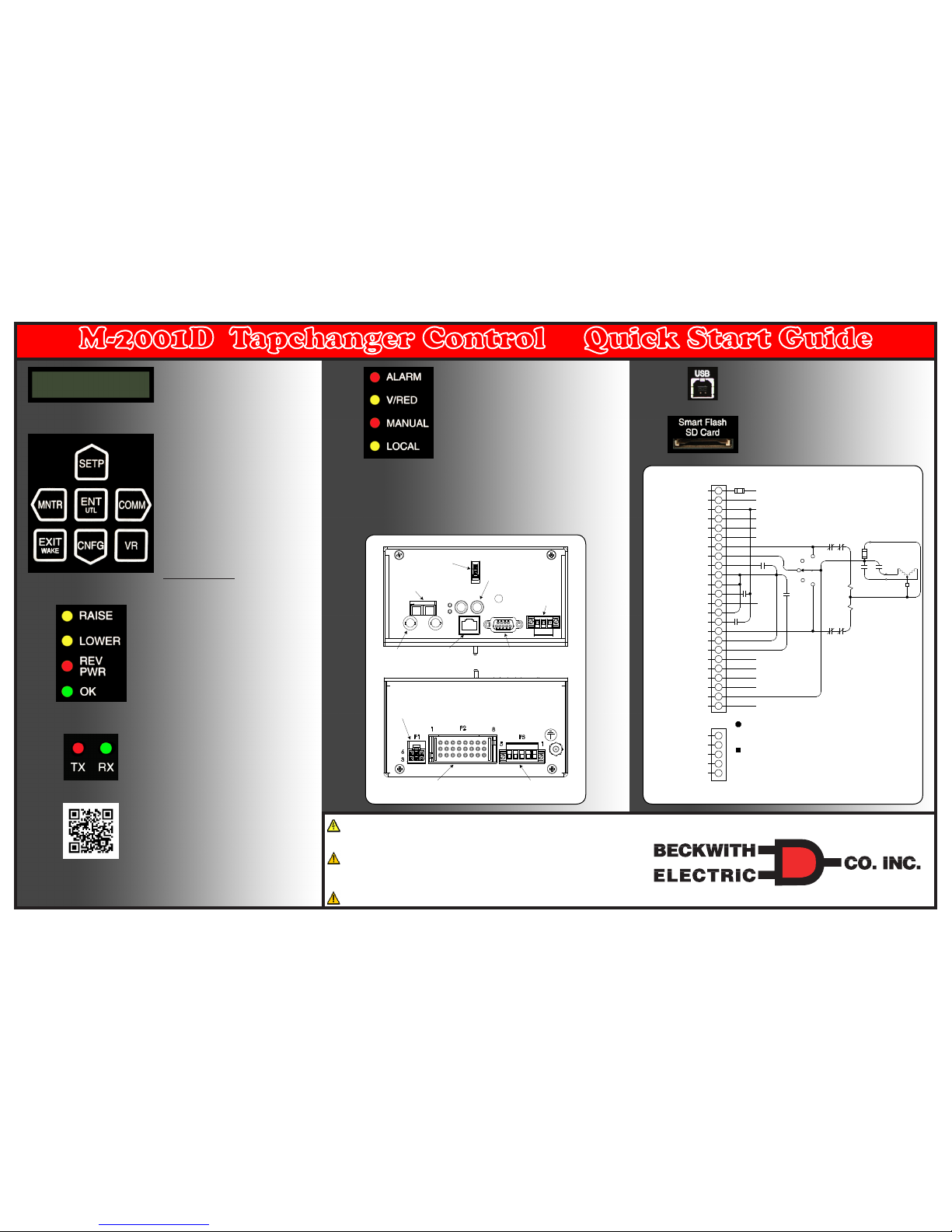
24-Pin Connector (P2)
Voltage Input (Polarity)
Neutral
Load Current (Return)
Load Current (Polarity)
Circulating Current (Polarity)
Circulating Current (Return)
Tapchanger Raise Output
Motor Power Input
Voltage Reduction Step #2 or
Contact KeepTrack 1R1L/1N Input
Contact "Wetting"
Supply + 12 Vdc
Operations Counter/
Switch Status Input #1
Operations Counter/
Switch Status Input #2
Input 1 Motor Seal-in/
Switch Status
Neutral Position Detector #1
Neutral Position Detector #2
Tapchanger Lower Output
Non-Sequential Operation/Auto
Tap Inhibit Input/SCADA Cutout
Voltage Reduction Step #1 or
Contact KeepTrack 1R1L/1N Input
Motor Seal-in Disconnect Output
User-Programmable Alarm
Self-Test Alarm
User-Programmable Alarm
Non-Interruptable
Pwr Supply Input
Self-Test Alarm
P3
Source Voltage Input
Aux Output
Aux Input A1
Or DVAr2 Disable Input
Aux Input A2
Aux Input A3
1
2
3
4
5
1
2
3
4
5
6
7
8
9
10
11
12
13
14
15
16
17
18
19
20
21
22
23
24
Fuse ¼ Amp
Voltage Input (Polarity)
Load Current (Return) See Note 2
Voltage Input (Return) See Note 2
Load Current (Polarity) 0.2 A
Circulating Current (Polarity) 0.2A
Circulating Current (Return)
Self-Test Alarm
(Return) See Note 4
User-Programmable
Alarm (Return)
Self-Test Alarm
(Input) See Note 4
User-Programmable
Alarm (Input)
Motor Seal-in
Note 3
AUTO
OFF
OFF
RAISE
LOWER
RAISE
LS
LOWER
LS
AL
INTERLOCK
AR
INTERLOCK
AUX LOWER (AL)
AUX RAISE (AR)
AL AR
MOTOR
FUSE 6 A
MOTOR POWER 120/240 V
See Note 1
R L
NOTES:
1. Motor voltage may be 120 or 240 V to neutral, or 240 V phase-to-phase.
2. The customer is to provide an earth ground connection to the CT/VT’s
neutral connection, external to the control.
3. To Motor Power Seal-In board.
4. If the M-2001D is configured for the SCAMP pushbutton Auto/Manual
Switch type, then the Self-Test Alarm relay is NOT available.
TX
Bottom View
Top View
Front
Fiber Optic V-Pin
Connector
(optional)
Fiber Optic ST
Connector
RJ-45 Ethernet over
Copper (optional)
Control Power
Backup Input
BlueTooth
Ethernet over Fiber
Optic (optional)
RS-485
RS-232 DE9S
In-Line, 6-Pin Connector
for the M-2025B, C or D
Current Loop Module
24-Pin Blue Connector for
M-2000 Series Adapter
Panels or Direct Connection
Source Voltage Input
One Aux Output
Three Aux Inputs
LCD SCREEN Pressing any pushbutton
will wake up the LCD and display the
heading corresponding to the “Hot Button”
label inside the pushbutton - WAKE, MNTR,
SETP, CNFG, COMM, UTIL, or VR.
EXIT/WAKE Pushbutton The EXIT WAKE
Pushbutton wakes the LCD from sleep
mode and begins scrolling through a list
of user programmed metered/calculated
values.
While navigating through the dierent HMI
menus the EXIT pushbutton is used to:
- Exit a level to the next higher level
- Cancel data entry
- Clear the screen when at the header level
VR Pushbutton Activates the user dened
Voltage Reduction Steps.
Shortcuts/Arrows
SETP Access to the Setpoints Screens.
MNTR Access to the Monitoring Screens.
ENT/UTL Pushbutton Access to the
Utilities screens and ENTER button.
While navigating through the dierent HMI
menus the ENT pushbutton is used to:
- Enter the edit mode of a screen
- Store a setpoint or condition in memory
- Enter the sub heading data level
- Reset certain monitoring screens
CNFG Access to the Conguration
Screens.
COMM Access to the Communication
Screens.
RAISE LED Out of Band Low Voltage.
LOWER LED Out of Band High Voltage.
REV PWR LED Indicates reverse power
ow.
OK LED Illuminates to indicate the micro
controller is functioning properly and is
extinguished when a Motor Seal-in Failure
Block is in eect.
COM1 TX/RX LEDS Indicates when
control is transmitting and/or receiving data.
ALARM LED Indicates any of the
programmable alarms are activated.
V/RED LED Indicates voltage reduction has
been invoked.
- Continuous illumination and one periodic
ash indicates Level 1 Voltage Reduction.
- Continuous illumination and two periodic
ashes indicates Level 2 Voltage Reduction.
- Continuous illumination and three periodic
ashes indicates Level 3 Voltage Reduction.
MANUAL LED Indicates automatic control is
disabled and in manual mode.
LOCAL LED Indicates control is switched
into Local mode. Cannot command control to
raise or lower via SCADA.
USB Port Used for Direct TapTalk®
Communications Connection.
Smart FlashCard Slot Used for loading
and saving setpoints, saving Datalog les,
SOE les, OSC les, Clone save and
load, load and save DNP les, Firmware
Update, save Wake-up Screens, save ALL
Metering Parameters and can be utilized
as an Access Code Key.
Scan this QR Code for direct
access to product software
and support documents.
Page 2
Press ENT to view
Tapchanger Status
Press ENT to view
Alarm Status
Press ENT to view
Input Status
Press ENT to view
Output Status
Peak RMS Curr
x.x mA (x.x) T
Avg RMS Curr
x.x mA (x.x) T
Profile Duration
XXXX.Xms(xxxx.x)T
Peak Motor Current E
x.x mA
Voltage % THD
x.x %
Current % THD
xx.x %
Press ENT to view
Voltage Harmonics
Press ENT to view
Current Harmonic
Status
Motor Current
Harmonics
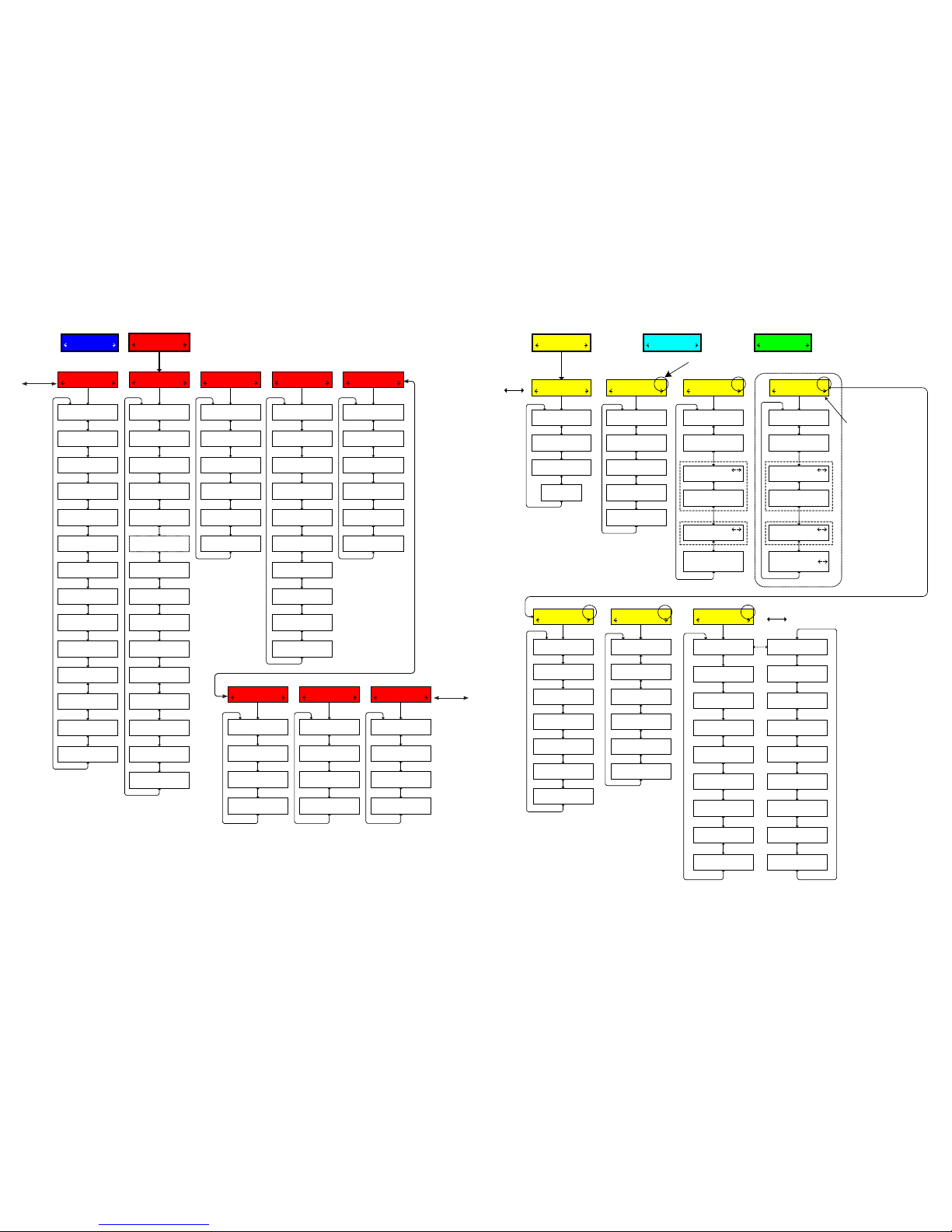
MONITOR
UTIL SETP
Tap Information
Present Demand
Demand History
Energy Metering
Tap Position/Cal
DISABLE
Drag Hands E
L= 0 N R= 0 N
Definite Timer
Raise xxs Lower xxs
Intertap Timer
xxx %
Operation Counter
x
Resettable Counter E
x
Neutral Sw Counter
x
Lower Counter
x
Raise Counter
x
Press ENT to view
specific Tap Stats
Press ENT to clear
Tap Statistics
RTN Success Counter
xxxxx
RTN Status
DISABLED
Count to RTN Active
xxxxx
Demand Interval
xx Min
Demand Load Voltage
xxx.x Volts
Demand Pri. Current
xxx.x Amps
Demand Pri. Watts
x.xx MW
Demand Pri. VArs
x.xx MVArs
Demand Pri. VA
x.xx MVA
Demand Interval
xx Min
Min Load Voltage E
x.x Volts
Max Load Voltage E
xxx.x Volts
Max Pri.Current E
xxx.x Amps
Max Primary Watts E
x.xx MW
Max Primary VArs E
x.xx MVAr
Max Primary VA E
x.xx MVA
PF @ Max VA E
x.xxx PF
Press ENT to reset
Demand History
Press ENT to perform
Master Reset
Watt Hours Fwd
E
x kWh
Lagging VAr Hours E
x kVArh
Watt Hours Rev E
xx kWh
Leading VAr Hours E
x kVArh
Press ENT to reset
Energy Metering
Press ENT to perform
Master Reset
If DVAr enabled
Metering
Load Voltage
xxx.x Volts
Meter Out Voltage
xxx.x Volts
Source Voltage
disabled
Load Current
x.x mA Lead/Lag
Circulating Current
x.x mA LEAD/LAG
DVar Current
x.x mA LEAD/LAG
Compensated Voltage
xxx.x Volts
Primary Voltage
x.xx kV
Primary Src Voltage
disabled
Primary Current
xxx.x Amps
Primary Watts
x.xx MW
Primary VArs
x.xx MVArs
Primary VA
x.xx MVA
Power Factor
x.xxx LEAD/LAG
Frequency
xx.x Hz
Load Voltage
xxx.x Volts
Watt Hours Fwd E
x.xxx MWh
Press ENT to view
Tapchanger Status
Press ENT to view
Alarm Status
Press ENT to view
Input Status
Press ENT to view
Output Status
Peak RMS Curr
x.x mA (x.x) T
Avg RMS Curr
x.x mA (x.x) T
Profile Duration
XXXX.Xms(xxxx.x)T
Peak Motor Current E
x.x mA
Voltage % THD
x.x %
Current % THD
xx.x %
Press ENT to view
Voltage Harmonics
Press ENT to view
Current Harmonic
Status
Motor Current
Harmonics
* Power Flow Reverse setting
screens are only available
when the "Reverse Power
Operation" selection under
"Common Settings" is selected
to either: REGULATE
REVERSE,
REG. R MEASURED SRC,
DISTRIBUTED GENERATION,
AUTO DETERMINE or
AUTO DETERMINE
MEASURED. If Distributed
Generation is selected, then
only LDC values can be set.
Selecting BLOCK, IGNORE or
RETURN TO NEUTRAL
disables the Power Flow
Reverse setting screens.
Active Setpoint Profile or Setpoint Profile
Selected for Editing
Limits 1
Profile Settings
Common Settings 1
Block Raise Voltage
xxx.x Volts
Block Lower Voltage
xxx.x Volts
Runup Deadband
x.x Volts
Current Block Limit
xxx mA
Runback Deadband
x.x Volts
Runup Enable/Disable
disable
Active Profile
1
Edit Profile 1 Name
"Empty"
Profile to Edit
1
Repeats for
Profiles 2-4
LDC Selection
RX
Timer Reset
INTEGRATING
Timer Characteristic
DEFINITE
Power Direction Bias
NONE
Rev Power Operation
BLOCK *
Bandcenter Fwd
xxx.x Volts
LDC X Fwd
x Volts
Bandwidth Fwd
x.x Volts
LDC Z Fwd
x Volts
With LDC R,X
With LDC Z
Bandcenter Rev
xxx.x Volts
Bandwidth Rev
x.x Volts
LDC X Fwd
x Volts
LDC Z Fwd
x Volts
With LDC R,X
With LDC Z
VAr Bias 1
Disable on Rev Pwr
disable
Set VAr Bias Method
Step
Set VAr Bias Method
disable (Step, Linear)
Fwd Max Cap Bnk Size
12000 KVAr
Rev Max Cap Bnk Size
12000 KVAr
Lead % Pickup
75
Lag % Pickup
75
VAr Bias Volt Step
1.0 Volts
Max VAR Bias Time
300 mins
Curr Mult Base Value
x
Disable on Rev Pwr
disable
Set VAr Bias Method
Linear
Linear V Bias -X
x Volts
Normlzd Lin V Bias -X
x.x Volts
Linear V Bias -X Lmt
x.x Volts
Linear V Bias +X
x Volts
Normlzd Lin V Bias +X
x.x Volts
Linear V Bias +X Lmt
x.x Volts
To Profile Settings
To VAr Bias
Voltage Reduction 1
VRed Turnoff Time
x Min
Smart VR
disable
Save VR at Power Off
DON"T SAVE
Standard VR
disable
Reduction Step 1 %
2.5
Reduction Step 3 %
7.5
Reduction Step 2 %
5.0
LDC R Fwd
x Volts
Definite(Inverse)
Delay Fwd
xx Sec
Power Flow Rev 1
Power Flow Fwd 1
LDC R Fwd
x Volts
Definite (Inverse)
Delay Fwd
xx Sec
SETPOINTS
MNTR CNFG
Sheet 2 of 4
800-M-2001D-QSG-08 (03-17)
At any menu screen:
Press EXIT to go to the Menu Header.
Press either to move sideways to the adjacent Menu Header.
COMMUNICATION
CNFG UTIL
CONFIGURATION
SETP COMM
UTILITIES
COMM MNTR
To
Harmonics
To Tap
Information
Page 3
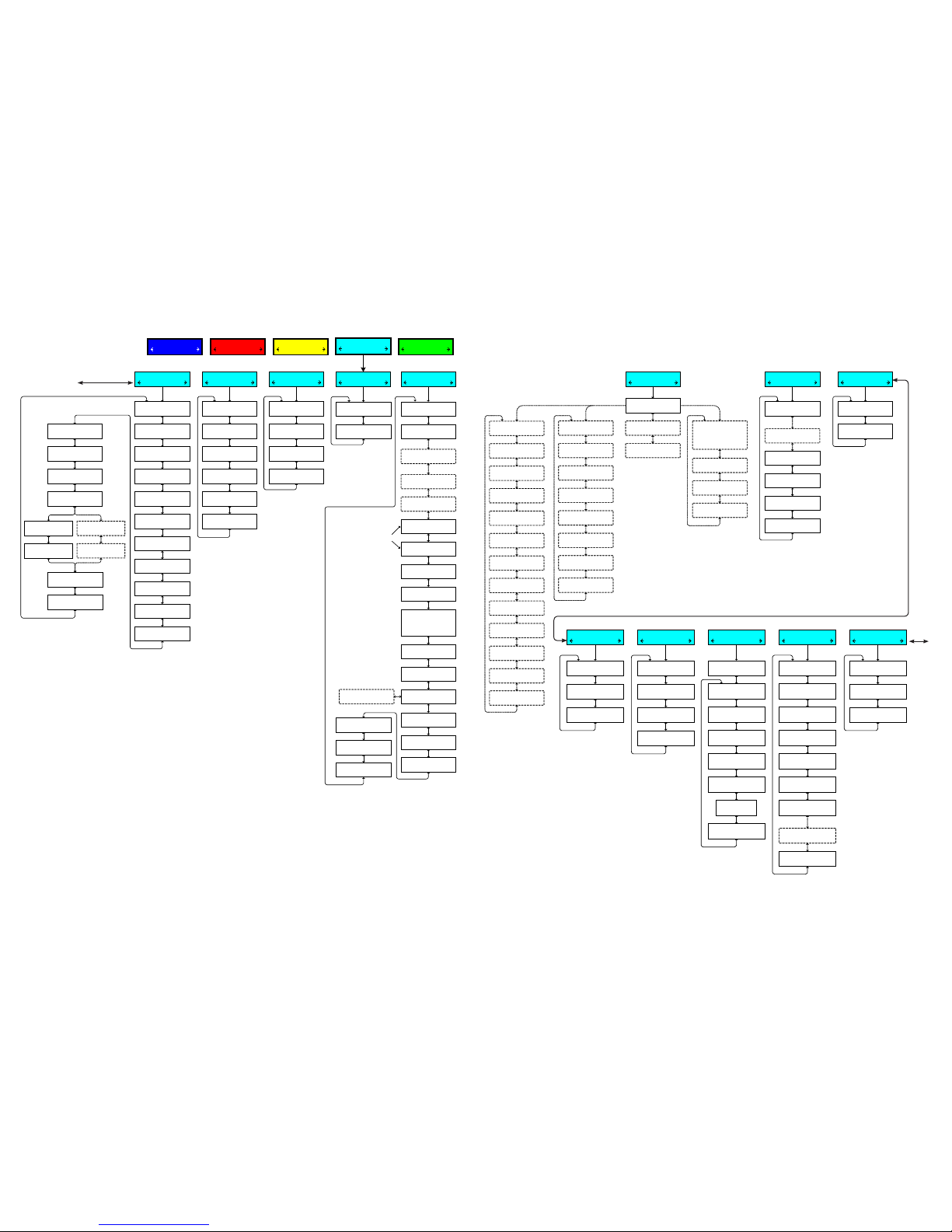
CONFIGURATION
SETP COMM
Tap Settings
Tapchanger Type
Remote Voltage Bias
Enable/Disable
disable
RVB HB Timer
x Secs
RVB Scale Factor
x.x
Rev RVB Scale Factor
x.x
Run Through Neutral
Enable/Disable
disable
Reset RTN Succ Ctr
Press ENT to begin
Max Allowed Taps
x
Max RTN Standby Ops
xx
Taps Between Runs
xxxx
Max Load Current
xx mA
Nameplate
Auto/Man Sw Type
SCAMP SWITCH
Scamp Init Pwrup
AUTO MODE
Auto/Man Sw Type
NONE/TOGGLE
Comm Block Auto
DON'T SAVE
CT Multiplier
xxxx X
Load VT Config
LINE_TO_GROUND
Aux Curr Transformer
xxx mA
CT/Load VT Phasing
x Deg
Load VT Multiplier
xx.x X
Load VT Correction
x.x Volts
CT/Source VT Phasing
x Deg
Source VT Multiplier
xx.x X
Source VT Correction
x.x Volts
Norm. VT. Multiplier
x.xx
Power Display Option
SINGLE_PHASE
Fast Volt Recovery
disable
Fast Volt R Setting
x.x V
Auto/Man Switch Type set to SCAMP
in Nameplate
Programmable Alarm
Prog Alarm Function
–<0000000000000000
Prog Alarm Function
NORMAL/AS DEADMAN OUT
Op Count Signal Alrm
x
Clear Sealin Alarm
Ready Press ENTER
Clr Low Current Blk
Ready Press ENTER
Clr RTN Fail To Opr
Ready Press ENTER
System Clock
Set Date and Time
xx/xx/xx xx:xx:xx
Daylight Savings
disable
Input Selection
Input Selection 1
SWITCH STATUS
Input Selection 2
NONSEQ INPUT
Input Selection 3
VOLTAGE RED 2
Mtr Current Profile
Peak RMS % Change
xxx
Average RMS % Change
xxx
Duration % Change
xxx
Init. Motor Current
Press ENT to reset
Regulator Type
TYPE A
Output Selection
CONTINUOUS
Output Pulse
x.x Sec
Low Current Block
disable
Paralleling
Tap Limits ENABLED
Not settable unless an
external source of Tap
Position is selected
Tap Position/Cal
DISABLE
Tap Information
disable
Tap Block Raise
xx
Tap Block Lower
–xx
Highest Tap
xx
Lowest Tap
–xx
Intertap Delay
x Sec
Seal-in Fail Block
ENABLE
Op Counter Config
1 X / 2 X/
COUNT WINDOW/
CAM FOLLOWER
Cam Follower
disable
X Mode Delay
xx ms
Op Counter Preset
xxxxxx
Ntrl Counter Preset
xxxxxx
Lower Counter Preset
xxxxxx
Tapchanger Type
LTC
Regulator Vendor
Default
Counter Time Window
x.x Sec
Raise Counter Preset
xxxxxx
Maximum Tap Wear
xxxxx
IndTapWear Alrm Set
100 %
Cooper Quick Drive
disable
Op Ctr = Count Window
Op Ctr = 1X/2X
Paralleling Type
DISABLE
Paralleling Type
DELTA VAR #1
Paralleling Type
CIRCULATING I
Paralleling Type
DISABLE
Paralleling Type
DELTA VAR #2
or
DELTA VAR #2 (KT)
DVAR2 Sensitivity
x.x
DVAR2 Reac I Lmt
xxx mA
DVAR2 I Ratio
x.xx
Paralleling Type
MASTER/FOLLOWER
MASTER/FOLLOWER
NONE
Paralleling Address
xx
Num. Devices
x
T.P.R. Timeout
xxxxx
Breaker Option
xxxxxx
Tap Difference
x
Clear Lockout Alarm
Ready Press ENTER
Paralleling Type
PEER2PEER DELTAVAR
P2P DVar Sensitivity
x.x
DVAR2 Reac I Lmt
xxx mA
Topology
Single Bus
Paralleling Address
xx
Num. Devices
x
P2P Update Speed
xxxxx
Clear Lockout Alarm
Ready Press ENTER
Load Side Brk Config
Not Used
Right Tie Brk Config
Not Used
Left Tie Brk Config
Not Used
MVA Rating
x.x
I Multi Correction
xxx %
Tap Limits
disable/ENABLE
Tap Info ENABLED
To Data Logging
Auto/Man Switch Type set to SCAMP
in Nameplate
Programmable Alarm
Prog Alarm Function
–<0000000000000000
Prog Alarm Function
NORMAL/AS DEADMAN OUT
Op Count Signal Alrm
x
Clear Sealin Alarm
Ready Press ENTER
Clr Low Current Blk
Ready Press ENTER
Clr RTN Fail To Opr
Ready Press ENTER
System Clock
Set Date and Time
xx/xx/xx xx:xx:xx
Daylight Savings
disable
Input Selection
Input Selection 1
SWITCH STATUS
Input Selection 2
NONSEQ INPUT
Input Selection 3
VOLTAGE RED 2
Mtr Current Profile
Peak RMS % Change
xxx
Average RMS % Change
xxx
Duration % Change
xxx
Init. Motor Current
Press ENT to reset
CBEMA Setup
Harmonics Setup
Data Logging
Data Log Select
111111111111111
Data Log Interval
x mins
Press ENT to clear
Data Log Records
Paralleling
Paralleling Type
DISABLE
Paralleling Type
DELTA VAR #1
Paralleling Type
CIRCULATING I
Paralleling Type
DISABLE
Paralleling Type
DELTA VAR #2
or
DELTA VAR #2 (KT)
DVAR2 Sensitivity
x.x
DVAR2 Reac I Lmt
xxx mA
DVAR2 I Ratio
x.xx
Paralleling Type
MASTER/FOLLOWER
MASTER/FOLLOWER
NONE
Paralleling Address
xx
Num. Devices
x
T.P.R. Timeout
xxxxx
Breaker Option
xxxxxx
Tap Difference
x
Clear Lockout Alarm
Ready Press ENTER
Paralleling Type
PEER2PEER DELTAVAR
P2P DVar Sensitivity
x.x
DVAR2 Reac I Lmt
xxx mA
Topology
Single Bus
Paralleling Address
xx
Num. Devices
x
P2P Update Speed
xxxxx
Clear Lockout Alarm
Ready Press ENTER
Load Side Brk Config
Not Used
Right Tie Brk Config
Not Used
Left Tie Brk Config
Not Used
MVA Rating
x.x
I Multi Correction
xxx %
Min I Thresh. ENABLED
Use TapTalk For
CBEMA in SOE or OSC
Event 1
ENABLE
Event1 Sag Pickup
xx %
Event1 Sag Dropout
xx %
Event1 Sag Min Dur
1 cycles (xx ms)
Repeats for
Events 2 thru 4
Clear All Counters
Ready Press ENTER
V 2-16 Har. Alarm
011101111111111
V 17-31 Har. Alarm
000000000000001
V Alarm Threshold
x.x %
I 2-16 Har. Alarm
011101011111111
I 17-31 Har. Alarm
000000000000001
I Alarm Threshold
xx %
Min I Thresh. Enable
ENABLE
Min Fund I Threshold
xx mA
Harmonic Alarm Delay
xx s
Normal Voltage
xxx.x Volts
Input Selection
Input Selection 1
SWITCH STATUS
Input Selection 2
NONSEQ INPUT
Input Selection 3
VOLTAGE RED 2
Mtr Current Profile
Peak RMS % Change
xxx
Average RMS % Change
xxx
Duration % Change
xxx
Init. Motor Current
Press ENT to reset
CBEMA Setup Harmonics Setup
Data Logging
Data Log Select
111111111111111
Data Log Interval
x mins
Press ENT to clear
Data Log Records
Min I Thresh. ENABLED
Use TapTalk For
CBEMA in SOE or OSC
Event 1
ENABLE
Event1 Sag Pickup
xx %
Event1 Sag Dropout
xx %
Event1 Sag Min Dur
1 cycles (xx ms)
Repeats for
Events 2 thru 4
Clear All Counters
Ready Press ENTER
V 2-16 Har. Alarm
011101111111111
V 17-31 Har. Alarm
000000000000001
V Alarm Threshold
x.x %
I 2-16 Har. Alarm
011101011111111
I 17-31 Har. Alarm
000000000000001
I Alarm Threshold
xx %
Min I Thresh. Enable
ENABLE
Min Fund I Threshold
xx mA
Harmonic Alarm Delay
xx s
Normal Voltage
xxx.x Volts
To
Nameplate
Sheet 3 of 4
800-M-2001D-QSG-08 (03-17)
At any menu screen:
Press EXIT to go to the Menu Header.
Press either to move sideways to the adjacent Menu Header.
COMMUNICATION
CNFG UTIL
MONITOR
UTIL SETP
SETPOINTS
MNTR CNFG
UTILITIES
COMM MNTR
Page 4
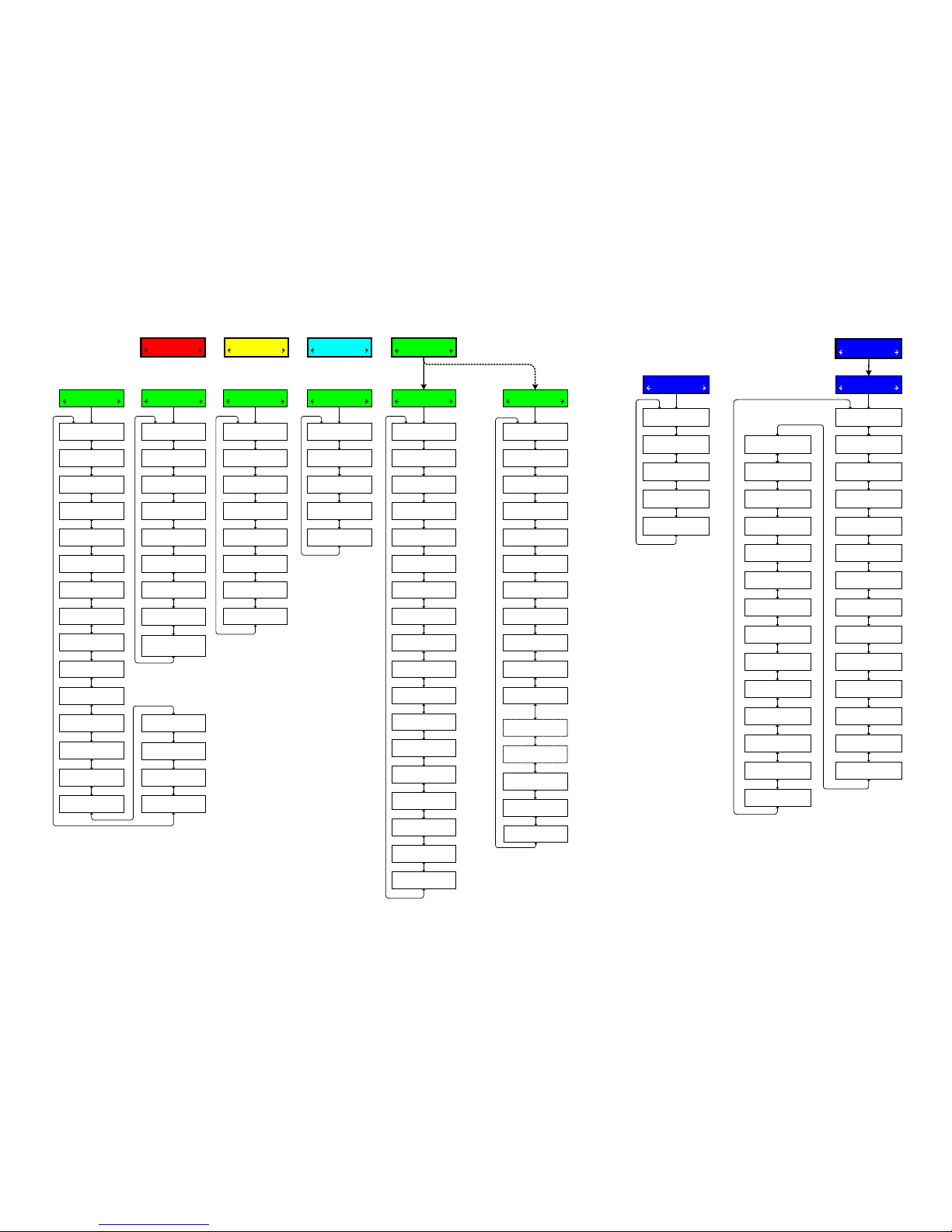
If Memory Card is present, the first menu
displayed under Communication is the
Memo
ry Card menu, otherwise the
Memory Card menu is not displayed.
If IEC 61850 is purchased
COMMUNICATION
CNFG UTIL
Memory Card
Load Setpoints
Press ENT to begin
Save Setpoints
Press ENT to begin
Save Datalog
Press ENT to begin
Save seq. of events
Press ENT to begin
Save oscillograph
Press ENT to begin
Clone save
Press ENT to begin
Clone load
Press ENT to begin
Load DNP Config
Press ENT to begin
Save DNP Config
Press ENT to begin
Save Metering Data
Press ENT to begin
Firmware Update
Press ENT to begin
Load IEC config
Press ENT to begin
Save IEC Config
Press ENT to begin
SD Quick Capture
Press ENT to begin
Comm Settings
Comm1 Port Type
RS485
Comm2 Port Type
RS232
Comm Protocol
DNP3.0
DNP Configuration
M2001D DNP DEFAULT
CID File ID
M2001D DEFAULT
Src Addr Validation
disable
Substation Address
DNP x
Feeder Address
DNP x
Comm Address
DNP x Mdbus x
Baud Rate
9600
Parity
NONE
Stop Bits
ONE STOPBIT
Sync Time
x mS
Output Pulse
x.x Sec
Comm Access Security
disable
Comm Access timeout
xx sec
TX Delay
xx ms
Heartbeat Option
Disabled
Protocol
MODBUS
Baud Rate
115200
Parity
NONE
Stop Bits
TWO STOPBITS
Sync Time
xx mS
RS232
Bluetooth Enable
ENABLE
Bluetooth Reset
Ready Press ENTER
Bluetooth Protocol
MODBUS
Authentication
disable
Friendly Name
M2001D-1
Bluetooth Pass Reset
Ready Press ENTER
Control BT Device
XX:XX:XX:XX:XX:XX
Bluetooth Mode
MODE0
Bluetooth
Set LCD Contrast: E
************
User Line 1 E
Beckwith Electric
User Line 2 E
M-2001D
Level 1 Access Code
Press ENT to change
Level 2 Access Code
Press ENT to change
Clear Osc Records
Ready Press ENTER
Oscillograph Message
ENABLE
HMI
DHCP Enable
ENABLE
IP Address
0.0.0.0
Net Mask
0.0.0.0
Gateway
0.0.0.0
Enter Modbus Port
502
Enter DNP Port
20000
Auto Negotiation
ENABLE
Keepalive time
7200 sec
Ethernet
Radius Server 1 IP
x. x. x. x
Radius Server 2 IP
x. x. x. x
Radius 1 Auth. Port
1812
Radius 2 Auth. Port
1814
Radius Secret Code
Press ENT to change
IEEE 1686 Standard
not used/
Authen with Encryp*
Radius 1 Acc. Port
1813
Radius 2 Acc. Port
1815
Radius En./Dis.
disable
IPSEC En./Dis.
disable
Load User config
Press ENT to begin
Load IPsec config
Press ENT to begin
SNTP Enable
disable
SNTP Server Address
0.0.0.0
Time Zone GMT
–5 Hr
UTILITIES
COMM MNTR
Bias Voltage
Status/Test Mode
Load Voltage
XXX.X Volts
Voltage Offset
X
Volt Cal Coefficient
32767 X
Volt RMS Coefficient
32762 X
Control Load I
x.x mA Lag/Lead
Curr Cal Coefficient
32767 X
Power Factor
x.xxx Lag/Lead
I Sin Coefficient
0 X
I Cos Coefficient
8192 X
Motor Current
x.xx mA
Mtr Cal. Coefficient
8192 X
Mtr Sin Coefficient
0 X
Mtr Cos Coefficient
8192 X
Calibration/Test
Mtr RMS Coefficient
8192 X
Circ Cal. Coefficien
32767 X
Circ Sin Coefficient
0 X
Circ Cos Coefficient
8192 X
LED Scroll Test
Press ENT to begin
Input Test
Press ENT to Begin
Output Test
Press ENT to test
Button Input Test
Press ENT to Begin
Change Src Input
press ENTER.
Watchdog resets: x
Total resets: xx
Clear reset counters
Press ENT to begin
X1 Duration
0 ms, Avg: 0 ms
Alarm Activity
Press ENT to Begin
About
Serial Number
xxxxx
Firmware Version
D-0214VXX.XX.XX
EE Checksum
XxXXXx
Last Loaded File CRC
x.x
Hardware Number
x
Comm Options En/Dis
11101111111111
Sheet 4 of 4
800-M-2001D-QSG-08 (03-17)
CONFIGURATION
SETP COMM
SETPOINTS
MNTR CNFG
MONITOR
UTIL SETP
© 2011 Beckwith Electric Co. All Rights Reserved
Technical Support
www.beckwithelectric.com / 727 544-2326
Email Support: [email protected]
*NOTE: Once IEEE 1686 Standard cyber security is enabled,
the user must enter a valid User Name and Password to
access any menus other than the "Utilities/About" menu. This
selection cannot be changed to "not used" without entering
a valid User Name and Password.
At any menu screen:
Press EXIT to go to the Menu Header.
Press either to move sideways to the adjacent Menu Header.
 Loading...