

Page 1

Chapter 1 Introduction
1.1 Foreword ................................................................................................ 1–1
1.2 Before You Begin ................................................................................... 1–2
1.3 Configuration As Shipped ...................................................................... 1–2
1.4 Description ............................................................................................. 1–3
1.5 Design Considerations........................................................................... 1–5
1.6 User Considerations .............................................................................. 1–7
TABLE OF CONTENTS
TABLE OF CONTENTS
M-0420 Multifunction Relay
Instruction Book
1.7 Options ................................................................................................... 1–8
1.8 Accessories ............................................................................................ 1–9
1.9 References ............................................................................................. 1–9
Chapter 2 Application
2.1 Protective Applications .......................................................................... 2–1
Islanding Protection (81U, 81O, 27, 59) ............................................... 2–1
Ferroresonance Protection (59I) ........................................................... 2–1
Utility-Side Ground Fault Protection and Phase Voltage
Unbalance Protection (27N, 59N) ......................................................... 2–2
Phase Fault Protection (51V, 67) .......................................................... 2–2
Directional Power (32F, 32R) ................................................................ 2–2
Anti-Motoring Protection (32R) .............................................................. 2–2
Ground Fault Protection (59N, 51N, 50N) ............................................ 2–2
Negative Sequence Overcurrent Protection (46) ................................. 2–3
Backup Phase Fault Protection (51VC/VR) .......................................... 2–3
VT Fuse-Loss Protection (60FL) ........................................................... 2–3
Power OK Status ................................................................................... 2–3
2.2 Trip Configuration vs. Applications ....................................................... 2–3
2.3 Intertie Protection................................................................................... 2–4
2.4 Generator Protection.............................................................................. 2–7
2.5 Setpoints............................................................................................... 2–11
2.6 Functions .............................................................................................. 2–12
81O/81U Over Frequency/Under Frequency ................................... 2–12
59/27 Overvoltage/Undervoltage ...................................................... 2–13
59I Peak Overvoltage........................................................................ 2–14
i
Page 2

M-0420 Instruction Book
59N/27N Overvoltage/Undervoltage,
Neutral Circuit or Zero Sequence ....................................................... 2–15
Ground Fault Detection Using 59N and Broken-Delta VTs ............... 2–16
Ground Fault Detection Using 27N and 59N with One VT ................ 2–17
51V Inverse Time Overcurrent, Three-Phase
with Voltage Control or Voltage Restraint........................................... 2–18
51N Inverse Time Overcurrent, Neutral Circuit................................ 2–24
50/50N Instantaneous Overcurrent,
Three-Phase and Neutral Circuits ....................................................... 2–25
46 Negative Sequence Overcurrent ................................................. 2–26
32 Directional Power, Three-Phase.................................................. 2–28
67 Phase Directional Overcurrent Option ........................................ 2–30
79 Reconnect Time Delay................................................................. 2–32
60FL VT Fuse-Loss Detection .......................................................... 2–33
2.7 Fault Recorder ..................................................................................... 2–33
Chapter 3 Front Panel Controls
3.1 Introduction............................................................................................. 3–1
3.2 Target/Status Indicators and Controls .................................................. 3–3
3.3 Serial Interfaces (COM1 and COM2).................................................... 3–3
Chapter 4 Operation
4.1 Introduction............................................................................................. 4–1
4.2 Software Flow ........................................................................................ 4–1
Power-On Self-Test and Status Screens .............................................. 4–1
Default Message Screens ..................................................................... 4–1
Access Screens ..................................................................................... 4–5
Menu Flow .............................................................................................. 4–5
4.3 Moving Between Menus ........................................................................ 4–5
4.4 Entering Values ...................................................................................... 4–5
4.5 Access Codes ........................................................................................ 4–8
4.6 Enabling and Disabling Relay Functions .............................................. 4–8
Chapter 5 Menu Reference
5.1 Introduction............................................................................................. 5–1
5.2 Relay Functions ..................................................................................... 5–1
5.3 Review Setpoints ................................................................................... 5–2
5.4 Monitor Status ........................................................................................ 5–2
5.5 Configure Relays.................................................................................... 5–3
5.6 View Target History ............................................................................... 5–4
5.7 Fault Recorder ....................................................................................... 5–4
5.8 Read Counter ......................................................................................... 5–5
ii
Page 3

5.9 Communication ...................................................................................... 5–5
5.10 Setup Unit............................................................................................... 5–6
5.11 Exit Local Mode ..................................................................................... 5–7
5.12 Menus ..................................................................................................... 5–8
Chapter 6 Installation
6.1 Initial Setup Procedure .......................................................................... 6–1
6.2 Commissioning Checkout ...................................................................... 6–2
6.3 DIP Switches .......................................................................................... 6–4
6.4 Mechanical/Physical Dimensions .......................................................... 6–6
6.5 Suggested VT Connections ................................................................. 6–10
6.6 UL-Listed Terminal Block Connections ............................................... 6–10
Chapter 7 Test Procedures
7.1 Introduction............................................................................................. 7–1
TABLE OF CONTENTS
7.2 Unit Setup............................................................................................... 7–1
7.3 Equipment Required .............................................................................. 7–2
7.4 Test and Equipment Setup .................................................................... 7–2
7.5 Diagnostic Test Procedures .................................................................. 7–5
Output Test ............................................................................................ 7–5
Input Test ............................................................................................... 7–6
LED Test ................................................................................................ 7–7
Button Test ............................................................................................. 7–7
Display Test ........................................................................................... 7–8
Backlight Test......................................................................................... 7–8
COM1 Test ............................................................................................. 7–9
COM2 Test ............................................................................................. 7–9
Other Diagnostic Mode Commands .................................................... 7–10
Power-On Self-Test ............................................................................. 7–11
59 RMS Overvoltage, 3-Phase ......................................................... 7–12
59N RMS Overvoltage, Neutral Circuit or Zero Sequence.............. 7–14
59I Peak Overvoltage........................................................................ 7–16
27 RMS Undervoltage, 3-Phase ....................................................... 7–18
27N RMS Undervoltage, Neutral Circuit or Zero Sequence............ 7–20
60 FL V.T. Fuse Loss Detection ....................................................... 7–22
81O Over Frequency ......................................................................... 7–23
81U Under Frequency ....................................................................... 7–24
50 Instantaneous Overcurrent, 3-Phase .......................................... 7–25
50N Instantaneous Overcurrent, Neutral ........................................ 7–26
51 Inverse Time Overcurrent, 3-Phase ............................................ 7–28
51VC Inverse Time Overcurrent with Voltage Control, 3-Phase ... 7–30
51VR Inverse Time Overcurrent with Voltage Restraint, 3-Phase 7–32
51N Inverse Time Overcurrent, Neutral ........................................... 7–34
46 Negative Sequence Overcurrent ................................................. 7–35
67 Phase Directional Overcurrent .................................................... 7–36
32F Directional Power, Forward Power, 3-Phase............................ 7–38
iii
Page 4

M-0420 Instruction Book
32R Directional Power, Reverse Power, 3-Phase ........................... 7–40
79 Reconnect Time Delay................................................................. 7–42
7.6 Self-Calibration Procedure................................................................... 7–43
Test Equipment .................................................................................... 7–43
Test Setup ............................................................................................ 7–43
Calibration Procedure .......................................................................... 7–44
Chapter 8 Design Changes
8.1 Introduction............................................................................................. 8–1
8.2 Host Processor Software Versions ....................................................... 8–1
Appendix A Theory of Operation
A.1 Introduction............................................................................................. A–1
A.2 System Block Diagram .......................................................................... A–2
A.3 Discrete Fourier Transform ................................................................... A–3
Estimation of RMS Value of the Signal................................................. A–4
Instantaneous Peak Voltage.................................................................. A–5
Estimation of the Fundamental Frequency ........................................... A–5
Calculation of Sequence Components .................................................. A–6
Calculation of Power/Power Factor ....................................................... A–6
Implementation of Inverse Time Overcurrent Relay Curves................ A–7
A.4 Acknowledgments .................................................................................. A–7
A.5 References ............................................................................................. A–7
Appendix B Self-Test Error Codes
Appendix C Communications
C.1 Introduction............................................................................................. C–1
C.2 The BECOCOM® Protocol..................................................................... C–1
C.3 Communication Ports............................................................................. C–1
C.4 Direct Terminal Communications via COM1......................................... C–2
Procedure for Terminal Communications via COM1............................ C–2
Appendix D Printed Circuit Board Interconnections
Appendix E Configuration Record Forms
iv
Page 5

TABLE OF CONTENTS
Figures Page
Chapter 1 Introduction
1-1 Traditional Relaying vs the M-0420 Multifunction Relay ...................... 1–4
1-2 M-0420 Block Diagram .......................................................................... 1–6
1-3 M-0420 Functional Diagram .................................................................. 1–6
1-4 M-0428A BECOPLOT™ Fault Data Analysis Software Output ........... 1–8
Chapter 2 Application
2-1 Intertie Protection – Typical One-Line Diagram ................................... 2–4
2-2 Intertie Protection – Typical Three-Line Diagram................................. 2–5
2-3 Intertie Protection – Trip Logic .............................................................. 2–6
2-4 Generator Protection – Typical One-Line Diagram .............................. 2–7
2-5 Generator Protection – Typical Three-Line Diagram ........................... 2–8
2-6 Generator Protection – Trip Logic ......................................................... 2–9
2-7 Example of Trip Characteristics: Over and Under Frequency ........... 2–11
2-8 Ground Fault Detection Using 59N and Broken-Delta VTs ............... 2–16
2-9 Ground Fault Detection Using 27N and 59N with One VT ................ 2–17
2-10 Voltage Restraint (51VR) Characteristic ............................................. 2–18
2-11 Definite Time Overcurrent Curve ........................................................ 2–20
2-12 Inverse Time Overcurrent Curve......................................................... 2–21
2-13 Very Inverse Time Overcurrent Curve ................................................ 2–22
2-14 Extremely Inverse Time Overcurrent Curve ....................................... 2–23
2-15 Negative Sequence Overcurrent Inverse Time Characteristic .......... 2–27
2-16 Phase Directional Overcurrent (67) Trip Characteristics ................... 2–31
Chapter 3 Front Panel Controls
3-1 M-0420 Front Panel ............................................................................... 3–2
Chapter 4 Operation
4-1 Software Flow ........................................................................................ 4–2
4-2 Power-on Self-Test and Status Screens............................................... 4–3
4-3 Default Message Screens ..................................................................... 4–4
4-4 Access Screens ..................................................................................... 4–6
4-5 Front Panel Operation ........................................................................... 4–7
v
Page 6

M-0420 Instruction Book
Chapter 5 Menu Reference
5-1 M-0420 Menu Flow, Version 4.01 Software ......................................... 5–8
5-2 Voltage Relay: RMS Overvoltage, 3-Phase (59) .................................. 5–9
5-3 Voltage Relay: Peak Overvoltage, 3-Phase (59I) .............................. 5–10
5-4 Voltage Relay: RMS Undervoltage, 3-Phase (27) .............................. 5–11
5-5 Voltage Relay: RMS Overvoltage Neutral Circuit or
Zero Sequence..................................................................................... 5–12
5-6 Voltage Relay: RMS Undervoltage, Neutral Circuit or
Zero Sequence (27N) .......................................................................... 5–13
5-7 Frequency Relay: Overfrequency (81O) ............................................. 5–14
5-8 Frequency Relay: Underfrequency (81U) ........................................... 5–15
5-9 Current Relay: Inverse Time Overcurrent, 3-Phase (51V) ................ 5–16
5-10 Current Relay: Phase Directional Overcurrent, 3-Phase (67) ........... 5–17
5-11 Current Relay: Inverse Time Overcurrent, Neutral (51N),
Instantaneous Overcurrent, Neutral (50N) ......................................... 5–18
5-12 Current Relay: Negative Sequence Overcurrent (46) ........................ 5–19
5-13 Power Relay: Forward Overpower (32F) ............................................ 5–20
5-14 Power Relay: Reverse Overpower (32R) ........................................... 5–21
5-15 Reonnect Relay (79) ............................................................................ 5–22
5-16 Review Setpoints ................................................................................. 5–23
5-17 Configuration of Phase Overcurrent Relay-67 Enabled ..................... 5–24
5-18 Example of Target History Screens .................................................... 5–27
Chapter 6 Installation
6-1 Internal Configuration DIP Switch–60 Hz ............................................. 6–5
6-2 Mounting Dimensions for GE L-2 Cabinet ............................................ 6–6
6-3 Mounting Dimensions for Westinghouse FT-41 Cabinet...................... 6–7
6-4 M-0420 Side View .................................................................................. 6–8
6-5 External Connections ............................................................................. 6–9
6-6 Connections for Wye-Wye Connected VTs ........................................ 6–10
6-7 Connections for Open-Delta Connected VTs ..................................... 6–10
6-8 Connections for Delta-Wye Connected VTs ....................................... 6–10
6-9 Wire Terminations for External Connection as Required
for UL Listing ........................................................................................ 6–10
vi
Page 7

Chapter 7 Test Procedures
7-1 Voltage Input Configuration ................................................................... 7–4
7-2 Current Input Configuration ................................................................... 7–4
7-3 Single-Phase Voltage Input Configuration for Calibration.................. 7–43
7-4 Single-Phase Current Input Configuration for Calibration .................. 7–43
Appendix A
A-1 System Block Diagram .......................................................................... A–2
A-2 Frequency Response of the DFT Algorithm ......................................... A–4
A-3 Phasor Diagram ..................................................................................... A–6
Appendix C
C-1 Null Modem Cable: M-0420 COM1 to PC (9-pin)................................. C–3
C-2 Null Modem Cable: M-0420 COM2 to PC (25-pin)............................... C–3
TABLE OF CONTENTS
Appendix D
D-1 M-0420 Board Interconnections ............................................................ D–1
Appendix E Configuration Record Forms
E-1 Functional Configuration Record ........................................................... E–2
E-2 Voltage Relay Setpoint Configuration Record ...................................... E–3
E-3 Frequency Relay Setpoint Configuration Record ................................. E–4
E-4 Current Relay Setpoint Configuration Record ...................................... E–5
E-5 Power and Reconnect Relay Setpoint Configuration Record .............. E–6
E-6 Internal DIP Switch Configuration Record ............................................ E–7
vii
Page 8

M-0420 Instruction Book
Tables Page
Chapter 1 Introduction
1-1 M-0420 Device Functions ...................................................................... 1–3
Chapter 2 Application
2-1 Current Transformer Placement Considerations for
Generator Phase-to-Phase Fault Protection....................................... 2–10
2-2 Over (81O) and Under (81U) Frequency Setpoint Ranges ............... 2–12
2-3 Overvoltage (59) and Undervoltage (27) Setpoint Ranges................ 2–13
2-4 Peak Overvoltage (59I) Setpoint Ranges ........................................... 2–14
2-5 Overvoltage (59N) and Undervoltage (27N) Setpoint Ranges .......... 2–15
2-6 Delta/Wye Transformer Voltage-Current Pairs ................................... 2–19
2-7 Inverse Time Overcurrent with Voltage Control/
Voltage Restraint (51VC/VR) Setpoint Ranges .................................. 2–19
2-8 Inverse Time Overcurrent Neutral (51N) Setpoint Ranges................ 2–24
2-9 Instantaneous Overcurrent (50) and Instantaneous Overcurrent
(50N) Neutral Setpoint Ranges ........................................................... 2–25
2-10 Negative Sequence Overcurrent (46) Setpoint Range....................... 2–26
2-11 Directional Power (32) Setpoint Ranges............................................. 2–29
2-12 Phase Directional Overcurrent (67) Setpoint Ranges ........................ 2–30
2-13 Reconnect Time Delay (79) Setpoint Ranges .................................... 2–32
Chapter 6 Installation
6-1 Internal Configuration DIP Switch ......................................................... 6–4
Chapter 7 Test Procedures
7-1 Initial Settings ......................................................................................... 7–3
7-2 Output Test Terminal Contacts ............................................................. 7–5
7-3 Input Test Terminal Contacts ................................................................ 7–6
7-4 LED Designations .................................................................................. 7–7
Appendix B Error Codes
B-1 Self-Test Error Codes ............................................................................ B–1
Appendix C Communications
C-1 Communication Port Signals ................................................................. C–2
C-2 Terminal Commands .............................................................................. C–2
viii
800-0420-IB-05 04/01
Page 9

1Introduction
1.1 Foreword .................................................................................... 1–1
1.2 Before You Begin .......................................................................1–2
1.3 Configuration As Shipped ..........................................................1–2
1.4 Description ................................................................................. 1–3
1.5 Design Considerations............................................................... 1–5
Introduction – 1
1.6 User Considerations ..................................................................1–7
1.7 Options .......................................................................................1–8
1.8 Accessories ................................................................................1–9
1.9 References .................................................................................1–9
1.1 Foreword
Beckwith Electric's multifunction protective relays
such as the M-0420 and M-0430 offer a number
of advantages to electric utilities seeking to optimize their protective systems:
Self-Diagnostics – The relay is constantly
checking its own operation. If not functioning
correctly, it alerts the operator through an output
contact. In contrast, single-function electromechanical relays must be tested periodically by
station maintenance personnel.
Fault Recording – The digital electronics in the
relay continuously record the waveform of the
voltage and current inputs, along with the status
contact inputs. When the breaker opens, as
indicated by the 52b contact, the waveform data
is stored in memory for later review when
investigating the cause of the trip.
Operation – All settings can be established or
changed using the front panel controls and
alphanumeric display.
Communication – Through a computer connec-
tion, all functions can be monitored and setpoints
changed by a PC-compatible computer, or by a
laptop PC plugged into the front panel.
Functions – The functions respond in the same
manner as do electromechanical relays, including time delays, and the nomenclature is the same.
This Instruction Book provides details of the
installation and operation of the relay. Our team
of applications engineers stands ready to assist
you in applying this equipment to your electric
system. Please don't hesitate to call us at (727)
544-2326.
Compact Size – The relay occupies a panel
space less than 8 inches wide and 21 inches high,
yet can operate fourteen protective functions.
1–1
Page 10

M-0420 Instruction Book
1.2 Before You Begin
The Beckwith Electric M-0420 Multifunction Relay is a sophisticated relay applicable to a wide
variety of applications. While it has been carefully designed to be easy to install and configure, if
you're a first-time user, we suggest that you acquaint yourself with its operation in the following
manner:
• Read this Introduction for a general over-
view of the relay.
• Read Chapter 2, Application, for informa-
tion on using the relay to protect generators and to initiate appropriate breaker
commands in response to faults and abnormal conditions.
• Refer to Chapters 3, Front Panel Controls
and 4, Operation, to familiarize yourself with
the layout and operation of the front-panel
controls.
• Refer to Chapter 5, Menu Reference, for
detailed information on the functions you will
be using in your application.
installation of the relay, please refer to Chapter
6, Installation.
If you are interested in a description of the relay's capabilities, please read this Introduction
thoroughly, and refer to Appendix A, Theory of
Operation, for more detailed information.
Please don't hesitate to call your local sales
representative or Beckwith's application engineers
(727-544-2326) for assistance in resolving any
problems.
1.3 Configuration As Shipped
You can become familiar with the basic operation of the relay before it is installed by connecting it to the appropriate power input and setting
it up on a bench or desktop. Even without any
test voltages connected, you will be able to step
through the various menus and note the indications on the liquid crystal display (LCD) and the
various light-emitting diodes (LEDs). The formal
initial setup information is presented in Chapter
6, Installation, which includes Figure 6-5 showing the external connections.
• Read Chapter 6, Installation, for mounting
dimensions, external connections, initial setup, and verification routines.
• Refer to Appendix E, Configuration Record
Forms for forms on which to record your
relay configuration and DIP switch settings.
• Refer to publication M-0429A BECOCOM®/
M-0428A BECOPLOT® User’s Guide for
information on configuring and interrogating
the relay via a personal computer running
the optional BECOCOM communications
software package, and for information on
plotting downloaded fault data via the optional
BECOPLOT software package.
The M-0420 Multifunction Relay Instruction Book
has been organized to address the needs of different parts of your organization. If you are responsible for verifying that the relay conforms to
specifications as received, please turn to Chapter 6, Installation for initial setup, and to Chapter 7, Test Procedures.
If you are responsible for the operation of the
relay in a specific application, please turn to Chapter 2, Application, for information on enabling
specific functions and entering setpoints. If you
are responsible for the mechanical and electrical
As shipped, the relay is in the following configuration:
• the clock has been disabled
• the second setpoints on various functions
have been disabled, and do not appear on
the display
• the DIP switch (at bottom of inside case)
has been set as below; setting is also detailed on the yellow or pink tag attached to
the equipment. (The yellow tag is for 60 Hz;
the pink tag is for 50 Hz.)
1)noitcelesresurofton(FFO
2)noitarbilacnahtrehtar,noitarepolamron(NO
3)edomcitsongaidnahtrehtar,noitarepolamron(NO
4)esahpynanodesnestnerruc/rewopesrever(NO
5)enil-ot-enilroftesstupniTV(NO
6)caV021siegatlovyradnocesTV(FFO
7)gatwolley-zH06siycneuqerfmetsys(FFO
)gatknip-ZH05siycneuqerfmetsys(NO
8)ylnotnenopmoclatnemadnufyb,SMR(FFO
1–2
Page 11

Introduction – 1
• the 51 voltage control and voltage restraint
functions are disabled
• the access code feature is disabled
• options supplied with the equipment are noted
on the yellow or pink (50 Hz) tag. These
are:
phase directional overcurrent function
(device 67)
input voltage (120 V ac, 125 V dc,
48 V dc, 24 V dc)
neutral current input (nominal 5 A or
1 A)
• a set of replacement fuses is attached to
one of the handles. These fuses are mounted
on the internal PC board.
noitcnuF noitpircseD
72 esahp-3,egatlovrednUSMR
N72ecneuqeSoreZrotiucriClartueN,egatlovrednUSMR
1.4 Description
The M-0420 Multifunction Relay is a
microprocessor-based unit that uses digital signal
processing technology to provide 14 different
protective relaying functions (see Table 1-1) in
one compact unit. The M-0420 is designed to
provide these functions in two basic applications:
generation, and generator/system interties. Within
these basic applications, the various devices in
the M-0420 can provide protection in cases of
islanding, ferroresonance, ground or phase faults,
generator motoring, and other abnormal operating
conditions. Internal relay functions are listed in
Table 1-1. The nomenclature follows the standards
of ANSI/IEEE Std. C37.2-1979, Standard Electric
Power Systems Device Function Numbers.
23
64esahp-3,yaleRtnerrucrevOecneuqeSevitageN
05 esahp-3,yaleRtnerrucrevOsuoenatnatsnI
N05lartueN,yaleRtnerrucrevOsuoenatnatsnI
N15 lartueN,yaleRtnerrucrevOemiTesrevnI
V15
95 esahp-3,yaleRegatlovrevOSMR
N95
I95 esahp-3,yaleRegatlovrevOkaeP
*76esahp-3,yaleRtnerrucrevOlanoitceriDesahP
97 yaleDemiTtcennoceR
O18ycneuqerfrevO
U18 ycneuqerfrednU
LF06noitceteDssoLesuF.T.V
dna)F23(drawroF,esahp-3,yaleRrewoPlanoitceriD
)R23(esreveR
htiw,esahp-3,yaleRtnerrucrevOemiTesrevnI
tniartseRegatloVrolortnoCegatloV
oreZrotiucriClartueN,yaleRegatlovrevOSMR
ecneuqeS
lanoitpO*
Table 1-1 M-0420 Device Functions
1–3
Page 12
M-0420 Instruction Book
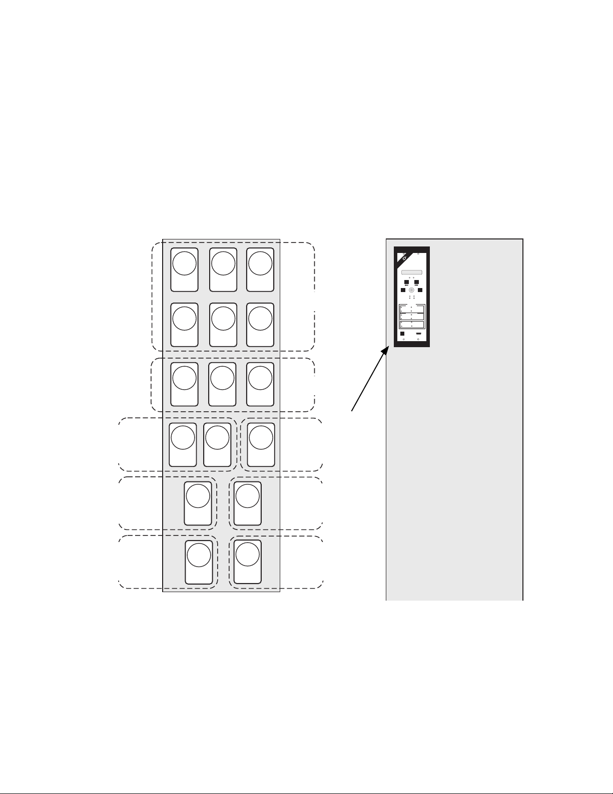
Since all functions are incorporated into one package, much less panel space and panel wiring is
required than for individual relays, as illustrated
in Figure 1-1. You can set and examine all functions via a menu-driven, 2-line by 24-character
LCD display or via remote communication access.
Once you reprogram a value, the new value is
placed in nonvolatile memory where it is unaffected by a loss of power or other system disturbance.
50/
51V
AF
67
AF
50/
51V
BF
67
BF
50/
51V
CF
Relay Functions
67
CF
The M-0420 Multifunction Relay includes multiple output and status input contacts. It can be
powered by 24, 48, or 125 V dc, or by 120 V ac,
50/60 Hz power, and is rated according to ANSI/
IEEE C37.90 and C37.90.1. The relay includes
self-test diagnostics, internal calibration correction, communication capability via two RS-232C
ports, real-time display of system parameters, trip
targets, and capture of fault data that occur during a system disturbance.
Phase Current
BECKWITH
ELECTRIC
VOLTAGE RELAY
VOLT freq curr
EXIT
RECORDED
OVERVOLTAGE
UNDERVOLTAGE
OVERVOLTAGE
UNDERVOLTAGE
OVERFREQUENCY
UNDERFREQUENCY
CO. INC.
PRIDE
M0420
MULTIFUNCTIO
N
SELECT
FUNCTION
POWER
FAULT
TARGETS
PHASE ELEMENTS
59
OVERCURRENT
27
INSTANTANEOUS
OVERCURRENT
NEUTRAL ELEMENTS
59 N
OVERCURRENT
27 N
INSTANTANEOUS
OVERCURRENT
81 O
NEGATIVE SEQUENCE
81 U
TARGET RESET/
LAMP TEST
Made in U.S.A.
®
➞
ENTER
SETPOINT
ENTER
RELAY OK
BREAKER
CLOSED
51/67
50
51 N
50 N
46
OVERCURRENT
32
DIRECTIONAL
OVERPOWER
SERIAL INTERFACE
COM 1
Neutral
Voltage Current Relay
Functions
Over/Under
Frequency
Relay Function
Directional Power
Relay Function
Figure 1-1 Traditional Relaying vs the M-0420 Multifunction Relay
27/
59
59I
AF
27/
59
BF CF
50/51N27/59
N
81
O/U
32
3F
46
79
27/
59
59I
A B C
F
Phase Voltage
Relay Functions
Peak
Overvoltage
Relay Function
Negative Sequence
Current Unbalance
Relay Function
Reconnect Time
Delay
Relay Function
1–4
Page 13

1.5 Design Considerations
Introduction – 1
There are basically two approaches in the design of digital relays. In the first approach, the
microprocessor simply replaces the relay logic
and does not process the voltage and current
signals. The performance of these relays depends
on the accuracy of the analog components used,
and is subject to dc offsets and gain drift with
temperature, supply voltage changes, or aging.
In the second approach, the microprocessor both
processes the signals and performs the logic,
providing a simpler design and offering performance advantages. The advent of low-cost digital signal processors (DSPs), microprocessors
designed especially for the efficient numerical
procedures required, paved the way for the design of a digital relay using state-of-the-art digital
signal processing techniques, thereby eliminating the problems inherent with analog hardware.
The Beckwith Electric M-0420 Multifunction Relay
follows this second approach: analog signalprocessing hardware is replaced with a DSP.
Various parameters of the input signals are
estimated using digital signal-processing
algorithms. The voltage and current input signals
of the relay are modeled as sinusoidal signals
corrupted by dc offset and harmonic components.
These signals can be characterized by various
parameters such as rms value, peak value, rms
value/phase angle, and frequency of the
fundamental component.
However, while DSPs are highly effective for signalprocessing applications, they are not very efficient for general purpose applications and have
limited memory space. Therefore, the relay uses
a dual-processor architecture. The DSP executes
all the signal-processing algorithms, while a general-purpose (host) processor manages input/
output and other overhead functions, monitors the
keyboard for operator requests, updates memories for setpoint values, facilitates operator interaction via the alphanumeric display, establishes
two-way communication using the RS-232C serial ports, analyzes the data from the DSP, and
issues the trip commands.
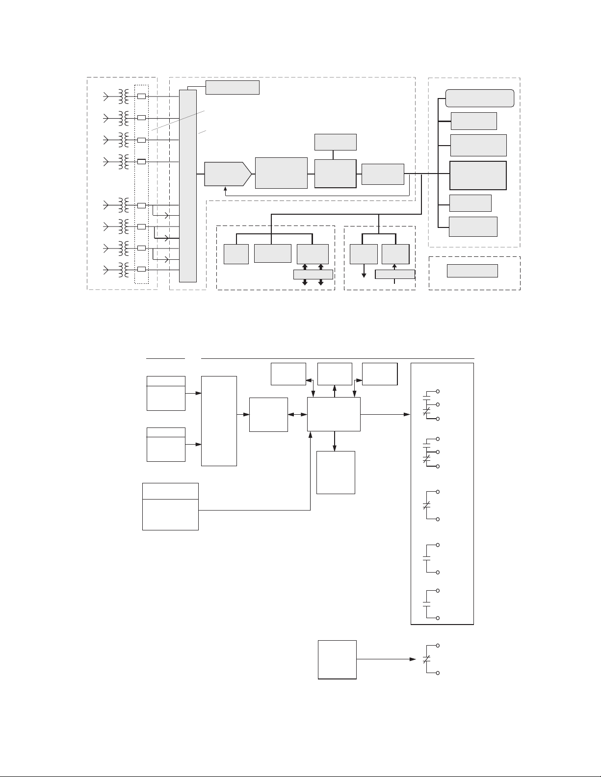
Figures 1-2 and 1-3 present a general overview
of the hardware design and functional operation
of the relay. As shown in these diagrams, the
inputs to the relay, filtered to remove higher order harmonics, are multiplexed and then passed
through an Analog-to-Digital Converter (ADC) to
the DSP, which performs a discrete Fourier transform (DFT) 16 times per cycle for each of the
inputs. The host processor performs all input/output
and overhead functions, including monitoring of
the status inputs, and ultimately analyzes the data
from the DSP to determine the need for a trip
command.
One significant design feature of the relay is
automatic correction of the sensing transformer
error caused by ambient temperature excursions.
Voltage transformers exhibit enough internal
resistance so that the internal regulation of the
transformer results in a significant error due to
changes in temperature. The relay includes a
temperature sensor mounted in the enclosure to
measure directly and accurately the internal
temperature of the relay. This temperature signal
is coupled through the ADC to the DSP, which
processes the information to determine the
appropriate factor required to correct the sensing
transformer error.
The relay uses an algorithm based on the DFT
to compute the frequency and to determine the
phase angle for real/reactive power measurements.
The algorithm uses voltage phasor estimates obtained from the DFT to compute reliable estimates
of frequency unaffected by dc and harmonic components in the signal. Additionally, deriving the
positive sequence voltage phasor from the DFT
means that the frequency function will continue
to operate should any single- or two-phase fault
occur.
1–5
Page 14
M-0420 Instruction Book
VTs & CTs
v
a
v
b
c
v
v
n
i
a
i
b
i
c
i
n
Input Board
Temperature
Sensor
Anti-Aliasing Low-Pass Filters (LPF)
Analog Multiplexer
8K byte
ROM
12-bit
LED
Analog-to-Digital
Converter
(ADC)
Front-Panel
Controls
Programmable
Gain Amplifier
MUX
i'
a
i'
b
i'
c
Targets
Front Panel Board
Digital Signal
Processor
TMS 32015
Address/Data Bus
RS 232
Serial I/O
Opto-Isolation
COM1 COM2
(DSP)
Figure 1-2 M-0420 Block Diagram
ANALOG
INPUTS M–0420 MULTIFUNCTION RELAY
VO LTAG E
3-PHASES
1-NEUTRAL
CURRENT
3-PHASES
1-NEUTRAL
STATUS
INPUT
1. BREAKER
STATUS 52b
2. VT FUSE LOSS
1. FILTERS
2. MUX
3. PGA
4. ADC
SERIAL
INTERFACE
DIGITAL
SIGNAL
PROCESSOR
TARGETS
HOST
PROCESSOR
RELAY
SETTINGS
IN
NON-
VOLATILE
MEMORY
DSP Processor Board
2K byte
Dual-Ported
RAM
Relay
Outputs
Output Board
Contact
Inputs
Opto-Isolation
USER
INTERFACE
Host Processor Board
2-Line by 24-Character
Liquid Crystal Display
32K byte RAM
128K byte Flash-
Lithium Battery
Power Supply
Power Supply Board
OUTPUT
RELAYS
1. TRIP
2. RECON ENABLE
3. SELF TEST
ALARM
4. TRIP ANNUN
Programmable
ROM
Host Processor
10 MHz 64180
EEPROM
RAM, Clock
10 Year
1–6
POWER
SUPPLY
AC OR
DC
Figure 1-3 M-0420 Functional Diagram
5. VT FUSE LOSS
6. PWR OK STAT
Page 15

1.6 User Considerations
Introduction – 1
In the design of the M-0420 Multifunction Relay,
careful consideration was given to making its use
as similar as possible to that of the traditional
protective relays that are still found throughout
typical power systems.
Ease of Use and Compatibility
In order to provide maximum compatibility with
existing equipment, care was taken that traditional
electromechanical nomenclature was used for
setpoint values and trip characteristics. For
example, the inverse time overcurrent functions
(devices 51 and 51N) use industry-accepted timecurve families (Definite Time, Inverse, Very Inverse,
and Extremely Inverse) based on the ABB (formerly
Westinghouse) CO and COV curves. Within each
family, the operator selects the tap setting and
time dial setting just as though doing so on an
electromechanical relay.
The user-friendly controls and display provide easy
access to the various functions. The software is
completely menu driven through a liquid crystal
alphanumeric display (LCD). All functions and
values can easily be set using the front panel
buttons and the rotary knob.
Communication Capabilities
One of the important features of the relay is its
capability for remote communications. The relay
provides two RS-232C serial ports for communication via modem or direct serial connection. In
a typical communications application, the rearpanel communication port is permanently connected to a modem, while the front-panel port is
kept free for on-site programming via a laptop
computer.
Fault Recording and Analysis
The multifunction relay provides up to 96 cycles
of fault waveform data with selectable distribution of the time before and after the breaker trip.
This data can be downloaded via an MS-DOS
computer running the M-0429A BECOCOM® Communications Software. Once downloaded, the data
can be analyzed using the associated M-0428A
BECOPLOT® Fault Data Analysis Software package.
The fault data analysis software runs on an
MS-DOS computer, enabling the user to plot fault
data, specifying which waveforms and inputs are
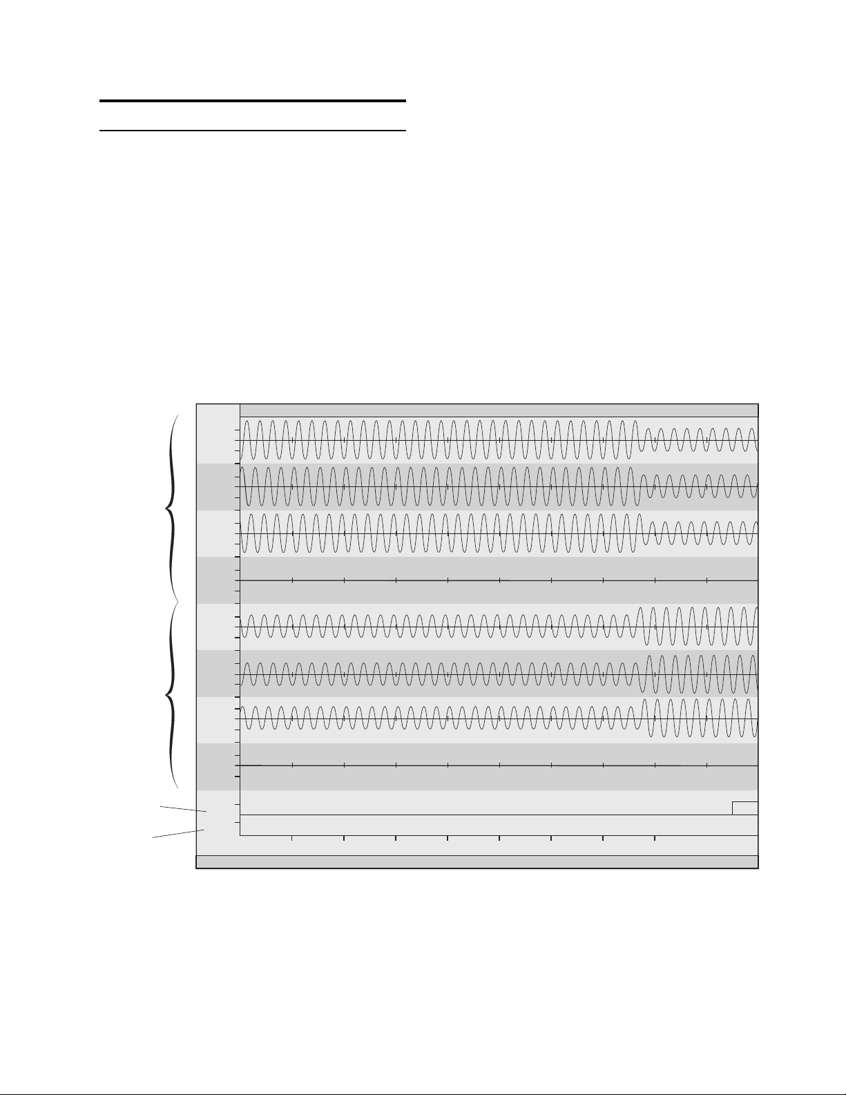
displayed, and at what scale. (The sample plot
shown in Figure 1-4 displays all waveforms.) A
marking feature enables the user to mark any
time span and zoom instantly to display it at full
screen, and specific points on the waveform may
be tagged in order to read actual waveform values.
Displayed plots can be printed using the DOS
Print Screen command.
Self-Diagnostics
To ensure confidence in the relay’s operation,
the system software provides many hardware and
software diagnostic checks, some of which are
performed continuously, and others on processor
reset. Should a failure occur, an output relay is
activated, and processing stops in order to prevent
mis-operation. Likewise, if system power fails, an
output contact closes.
Internal Calibration Correction
One of the most important and novel advantages
of the relay is its capability for correcting its
calibration through internal software. Most existing
static and microprocessor relays are designed
with a number of trim pots to trim the signal offsets,
and gain and phase inaccuracies. This can be a
time-consuming process, during both factory
calibration and routine calibration by the customer.
The relay does away entirely with trim pots for
calibration. The gain and phase angle errors are
computed using calibration coefficients stored in
nonvolatile memory. When the calibration mode
is selected, the relay display prompts the operator
to connect the voltage inputs to 120 V and the
current inputs to 5 A with zero phase angle between
the signals. Then, the relay computes the gain
and phase angle errors and stores the appropriate
correction coefficients for use by the relay software.
1–7
Page 16
M-0420 Instruction Book
1.7 Options
In addition to the selectable power inputs of 24,
48, or 125 V dc/120 V ac (50 or 60 Hz), the relay
can provide the following optional functions:
67 Phase Directional Overcurrent
The relay is available with the phase directional
overcurrent function (67). In addition to the definite
time delay provided on the 67 function, the
directional element of the 67 function can be used
to provide directional control of the 51V function,
thereby realizing a directional inverse time
overcurrent function.
File: FAULT.DAT Time Tag: 11/15/91 10:13:32
1165.7 1219.6 1273.4 1327.3 1381.1 1435
Voltages
Currents
52b Breaker
Input Status
Fuse Loss
1.2 pu
0.6
Va
0.6
1.2 pu
0.6
Vb
0.6
1 pu
0.5
Vc
0.5
0.1 pu
0.05
Vn
0.05
4 pu
2
Ia
2
4 pu
2
Ib
2
4 pu
2
Ic
2
0.4 pu
0.2
In
0.2
52b
60FL
time
1004.2 1058
(ms)
H:Help X:Zmin x:Zmout Y:Zmin y:Zmout ->:Next <-:Prev C:Cursor R:Read Q:Quit
1111.9
Neutral Current Input
The relay is available with a nominal neutral current
input of 5 A (standard) or 1 A (optional). When
the 1 A input option is chosen, the relay internally
scales the current by a factor of 5 and the settings
and status display work as though the 5 A nominal
neutral current is selected. With the 1 A neutral
current input, the current-related settings and status
display values should be divided by 5 to obtain
the actual current values.
1488.9
1–8
Figure 1-4 M-0428A BECOPLOT® Fault Data Analysis Software Output
Page 17

Introduction – 1
1.8 Accessories
M-0319 Dropping Regulator
The M-0319 Dropping Regulator is a resistor/zenerdiode regulating device used to produce 125 V
dc from a 250 V dc battery source. The regulator
can be used to allow an M-0420 Multifunction
Relay with the 120 V ac/125 V dc power supply
option to operate from a 250 V dc source.
M-0421 PRIDE® Test Adapter
The M-0421 Test Adapter makes bench testing
the relay an easy process. The adapter provides
a complete set of rear terminals for testing the
unit after it has been removed from its draw-out
case.
M-0429A BECOCOM® Communications
Software Package
The BECOCOM communications software runs
on an MS-DOS computer, providing remote access to the relay via either direct serial connection or modem. BECOCOM provides the following
communication functions:
• Setpoint interrogation and modification
• Line status real-time monitoring
• Downloading recorded fault data
BECOCOM also provides remote access to the
Beckwith Electric M-0430 Multifunction Relay.
1.9 References
The references that follow provide additional information about the use of digital technology in
protective relaying. References 12 and 13 present
more detailed information about the design and
relay applications, and are available upon request
from Beckwith Electric Co., Inc.
[1]
Grid Interconnection Performance Requirements and Current Practice
Institute, Topical Report 87-0117, 1986.
[2]
IEEE Guide for Interfacing Dispersed Stor-
. Gas Research
age and Generation Facilities with Electric
Utility Systems
[3]
Intertie Protection of Consumer-Owned
Sources of Generation
Publication 88TH0224-6-PWR.
[4] ANSI/IEEE C37.102-1987 “
AC Generator Protection
[5] M.S. Sachdev (Coordinator),
sor Relays and Protection Systems
Tutorial Text, 88EH0269-1-PWR.
[6] W.E. Feero, W.B. Gish, and C.L. Wagner,
“
Overvoltages on Distribution System Gen-
. ANSI/IEEE Std. 1001-1988.
, 3 MVA or Less. IEEE
IEEE Guide for
.”
Microproces-
. IEEE
eration Separated from the Power Systems
Final Report ERM-8701-07, April 1987, Electric Research and Management, Inc., State
College, PA, 16804.
,”
M-0428A BECOPLOT® Fault Data Analysis
Software Package
The M-0428A BECOPLOT Fault Data Analysis
Software runs on any MS-DOS computer, enabling
you to plot and print fault data downloaded (using the BECOCOM communications software
package) from the M-0420 and M-0430 relays.
Figure 1-4 illustrates typical data output.
M-0422/M-0423 Serial Communications
Cables
The M-0422 cable is a 10 foot straight-through
RS-232 cable for use between the relay's rearpanel (COM2) port and a modem. This cable has
DB25 (25-pin) connectors at each end.
The M-0423 cable is a 10 foot null-modem RS-232
cable for direct connection between a PC and
the M-0420 front-panel (COM1) port. This cable
has DB9 (9-pin) connectors at each end.
[7] A.G. Phadke, J.S. Thorp, and M.G. Adami-
ak, “
A New Measurement Technique for
Tracking Voltage Phasors, Local System
Frequency, and Rate-of-Change of Frequency
.” IEEE Transactions on PAS, vol. PAS-
102, No. 5, May 1983, pp. 1025-1038.
[8] David M. Denison, “
Application of Digital Fault
Recorders on the Tampa Electric Company
System
Conference, Georgia Institute of Technology, Atlanta, Georgia, May 2-4, 1990.
[9]
Electric Utility Systems and Practices
Edition, Homer M. Rustebakke, John Wiley
& Sons, 1983.
[10]
Protective Relaying, Principles and
Applications
Dekker, Inc., 1987.
,” 44th Annual Protective Relaying
, 4th
, J. Lewis Blackburn, Marcel
1–9
Page 18

M-0420 Instruction Book
[11] C.F. Henville, “
grading Projects
Relay Replacement and Up-
,” Canadian Electrical Association 1991 Spring Meeting, Toronto,
Ontario, May, 1991.
[12] Murty V. V. S. Yalla, Donald L. Hornak, “
Digital Multifunction Relay for Intertie and
Generator Protection
,” Canadian Electrical
Association 1992 Spring Meeting, Vancouver, B.C., March 1992.
[13] Murty V. V. S. Yalla, “
Protective Relay
A Digital Multifunction
,” IEEE Transactions on
Power Delivery, Vol. 7, No. 1, January 1992,
pp. 193-201.
A
1–10
Page 19

2Application
2.1 Protective Applications .............................................................. 2–1
2.2 Trip Configuration vs Applications ............................................ 2–3
2.3 Intertie Protection....................................................................... 2–4
2.4 Generator Protection..................................................................2–7
2.5 Setpoints...................................................................................2–11
2.6 Function ....................................................................................2–12
81O/81U Overfrequency/Underfrequency...............................2–12
59/27 Overvoltage/Undervoltage............................................. 2–13
59I Peak Overvoltage ..............................................................2–14
59N/27N Overvoltage/Undervoltage, Neutral Circuit
or Zero Sequence ....................................................................2–15
Ground Fault Detection Using 59N and Broken-Delta VTs ...2–16
Ground Fault Detection Using 27N and 59N with One VT ....2–17
51V Inverse Time Overcurrent, 3-Phase, with
Voltage Control and Voltage Restraint....................................2–18
51N Inverse Time Overcurrent, Neutral Circuit ......................2–24
50/50N Instantaneous Overcurrent, 3-Phase
and Neutral Circuit ................................................................... 2–25
46 Negative Sequence Overcurrent ........................................2–26
32 Directional Power, 3-Phase................................................ 2–28
67 Phase Directional Overcurrent Option ...............................2–30
79 Reconnect Time Delay .......................................................2–32
60FL VT Fuse Loss Detection.................................................2–33
Application – 2
2.7 Fault Recorder .........................................................................2–33
2.1 Protective Applications
The sections that follow discuss briefly the principal
applications of the M-0420 Multifunction Relay in
intertie or generator protection. Section 2.6,
Functions, discusses the individual functions in
detail, presenting setpoint ranges, increments, and
the initial default settings.
Islanding Protection (81U, 81O, 27, 59)
When a dispersed source of generation (DSG) is
suddenly islanded, the frequency will quickly shift
from 60.0 Hz (except for the improbable case of
an exact generation and load match), making the
measurement of frequency an excellent means
of detecting the island condition. The relay provides
both under frequency (81U) and over frequency
(81O) functions. The relay also provides both rms
undervoltage (27) and rms overvoltage (59)
functions that can be useful in detecting islanding.
Each has two setpoints with time delays from 1
to 8160 cycles, and magnitude range settings from
10 to 200 V.
Ferroresonance Protection (59I)
Lightly loaded islanded systems can experience
ferroresonance, where the system is in resonance
but the inductance is highly nonlinear as the
transformer core cycles in and out of magnetic
saturation. Under these conditions, the voltage
waveform will be distorted to the extent that the
peak voltage of the non-sinusoidal wave can be
dangerously high. Since the peak overvoltage (59I)
2–1
Page 20

M-0420 Instruction Book
function of the relay detects the value of the
instantaneously sampled wave, it can act in
situations where a relay reacting to rms voltage
would not. The setpoint range is from 1.05 to 1.50
per unit, with a time delay variable from 1 to 8160
cycles.
Utility-Side Ground Fault Protection and
Phase Voltage Unbalance Protection (27N,
59N)
The relay provides both rms undervoltage and
rms overvoltage functions for the neutral circuit
(27N and 59N). Used together with one VT connected from any one phase to ground, the 27N
and 59N devices are an effective means of detecting the most common line-to-ground fault. A
fault on the phase that includes the VT will pull
that phase voltage low and initiate operation of
the 27N function. A fault on either phase without
the VT will result in S3 x normal voltage appearing at the VT, initiating operation of the 59N.
The 59N may also be used to detect system phase
voltage unbalance conditions in conjunction with
three VTs. To do so, the VT secondaries are connected in broken delta and the 59N device inserted. In this case, voltage at the 59N will be
zero so long as the three-phase voltages are
balanced, but will rise above zero with any unbalanced condition, as will occur with a utility line
or ground fault.
line-side CT inputs are used, this function can
also provide high-speed protection against generator winding faults. However, with line-side CTs,
the protection against winding faults during offline operation (when the breaker is open) is not
available from the 51V, 50, 46, or 67 functions.
Calculation of the current used for tripping is a
unique feature of this relay. The current is derived
from an RMS calculation, but (by user selection)
can also be computed based on either including
or not including the contribution of harmonics to
the value. Since it is not well established by the
industry whether the calculation should be based
simply upon the fundamental frequency component
or a broader frequency range, a simple switch
setting allows the operator to select either one.
Directional Power (32F, 32R)
Implementation of the directional power function
is straightforward, issuing a trip command when
the magnitude of the power flow (in either direction as selected) exceeds the setpoint for the prescribed time. However, as opposed to reverse
power relays that rely on zero crossings for phase
angle information, the relay power calculation uses
the fundamental frequency phasor measurements
obtained from the DFT, and thus is immune to
harmonics in voltage and current signals. The
setpoints for either direction range from 0.02 to
3.0 pu, with time delays from 1 to 8160 cycles.
Implementation of the 27N and 59N functions provides two setpoints each with a range setting of
10 to 200 V and a time delay of 1 to 8160 cycles.
Phase Fault Protection (51V, 67)
Time overcurrent relays (51), one per phase, are
basic to any protection scheme. This is the main
device used to trip circuits selectively and timecoordinate them with other up- or downstream
devices. Four complete series of inverse time tripping characteristics from Definite Time to Extremely
Inverse (based on the ABB CO and COV curves)
are included in the relay.
For intertie protection applications, the optional
phase directional overcurrent function (67) allows
greater selectivity for utility system faults, since
the directional element can be set to look toward
the utility system. As a generator protection relay, the 67 function, looking into the generator,
can provide protection against accidental energization of the generator on turning gear. When
Anti-Motoring Protection (32R)
When the energy supply to the prime mover is
cut off while the generator is still on line, the generator will act as a synchronous motor driving
the prime mover. A reverse power relay is used
to detect this motoring. Because the power required to motor is a function of the type of prime
mover, the required sensitivity of the reverse power
relay can vary widely for different applications.
The reverse power function provides 2% sensitivity, making it applicable to many anti-motoring
situations. A time delay of up to 8160 cycles can
be set to avoid tripping during power swings.
Ground Fault Protection (59N, 51N, 50N)
Detection of ground faults in a high-impedancegrounded unit generator can be accomplished by
an overvoltage relay in the generator neutral. For
good fault sensitivity, the pickup of the relay should
be about 10 to 16 V. However, because the third
harmonics which normally flow in the system and
2–2
Page 21

Application – 2
neutral can easily exceed this value, they must
be filtered, or the relay otherwise made insensitive
to them. For this application, the relay responds
only to the fundamental frequency component of
the neutral voltage signal.
In such a high-impedance grounding system,
ground faults in the primary system will induce
zero-sequence voltages at the generator due to
capacitive coupling between the windings of the
unit transformer. If the coupling voltage is
anticipated to be greater than the 59 relay pickup,
a time delay should be used to permit the primary
ground relays to clear high-side faults. The relay
provides a variable time delay of 1 to 8160 cycles.
Alternative or additional protection can be provided
with the use of an inverse-time overcurrent relay
(51N) and/or an instantaneous overcurrent relay
(50N). These relays must be set above the
maximum unbalance current that normally flows
in the generator neutral. A typical setting for the
51N function would be 1.5 to 2 times the typical
value. Because the 50N function provides
instantaneous protection, it must be set above
the greater of normal neutral unbalance and the
maximum current resulting from primary system
ground faults. A typical setting would be 2 to 3
times the maximum.
Negative Sequence Overcurrent Protection (46)
Unbalanced faults and other system conditions
can cause negative sequence currents in the
generator, leading to second-harmonic currents
in the rotor that can cause severe overheating
and damage. The relay implements the inverse
time negative sequence overcurrent function
2
(I
t=K) in order to protect the generator from
2
the unbalanced currents.
Backup Phase Fault Protection (51VC/VR)
Backup protection for system phase faults can
be provided by a voltage-controlled/restrained inverse-time overcurrent relay (51VC/VR). The voltage restraint function is well-suited to small
generators with relatively short stator time constants. The voltage control feature helps to confirm that the overcurrent is due to a fault by
activating the function only when the voltage is
below the voltage control setpoint. Additionally,
the relay can determine the equivalent high-side
voltages of delta/wye unit transformers through
its internal software, thus eliminating the need
for auxiliary instrument transformers.
VT Fuse-Loss Protection (60FL)
If the internal blown-fuse detection is enabled, or
the external fuse-loss input is connected, the relay
provides user-selectable blocking of the 27, 51V,
67, and 32R functions upon detection of a VT
fuse-loss condition. Additionally, the relay will
activate an output contact indicating the blownfuse condition. This external contact can be used
to block other relays which may be affected by
the blown-fuse condition (for example, a loss-offield relay).
POWER OK STATUS
The green POWER LED on the front panel remains
on as long as power is applied and the power
supply is operating properly. When system power
fails or is removed, a normally-closed output relay
opens to provide an alarm function.
2.2 Trip Configuration vs. Applications
Figures 2-1 through 2-6 illustrate the protection
capabilities and trip logic for both intertie and
generator protection modes. To optimize the relay
for the specific application, access the
CONFIGURE RELAYS menu (see Chapter 5,
Menu Reference) and do the following:
1. Press ENTER. The legend VOLTAGE
RELAY will appear on the display.
2. Turn the rotary knob four steps to the right.
The legend CONFIGURE TRIP CIRCUIT will
appear on the top line, and TRIP will appear
on the bottom line.
3. Press ENTER. The legend TRIP CIRCUIT
TYPE will appear on the top line, with the
two choices INTERTIE and generator on
the bottom line.
4. Select one of these, using the rotary knob,
and press ENTER.
When INTERTIE is selected, all functions are
available at all times (individual functions can be
disabled via the CONFIGURE RELAYS menu).
When GENERATOR is selected, the relay disables the 27, 81O, 81U, 27N, 32F, and 32R functions when the 52b status input indicates that the
breaker is open. This feature ensures that the
relay will not send an unwanted trip signal while
the generator is off-line, such as when being
brought up to speed.
2–3
Page 22
M-0420 Instruction Book
When GENERATOR is selected, the following
conditions must be true:
• The 52b status input
• High-speed reverse power
must
be connected.
must not
be se-
lected.
■ NOTE: For generator protection during off-nom-
inal frequency operation, more accurate response
will be achieved if the total waveform (including
harmonics) is used as the basis for the rms magnitude of voltage and current. (This option is selected via the internal configuration DIP switch
as explained in Chapter 6, Installation.)
Utility System
n NOTES:
* Voltage transformer connection may be either
broken delta or single phase, depending on
application.
** Voltage transformer connection may be wye,
open delta, or delta.
a Since only one neutral voltage input is
provided, the 59N function may be used in
one of the locations shown, but not both
simultaneously. If 59N is used for generator
neutral fault detection, it is not available for
utility ground fault monitoring.
b Since only one neutral current input is
provided, the 50N/51N functions can be used
in one of the locations shown but not all
simultaneously. 50N/51N can be used in
high- or low-impedance grounding
applications or to detect ground fault currents
on the grounded wye side of the power
transformer.
c 51V may be either 51VC or 51VR, with or
without directional (67) control.
d 67 (Phase Directional Overcurrent) is optional.
e 60FL = VT Fuse Loss detector.
f M-0420 trips and initiates permissive
reconnect for the 52I circuit breaker.
2.3 Intertie Protection
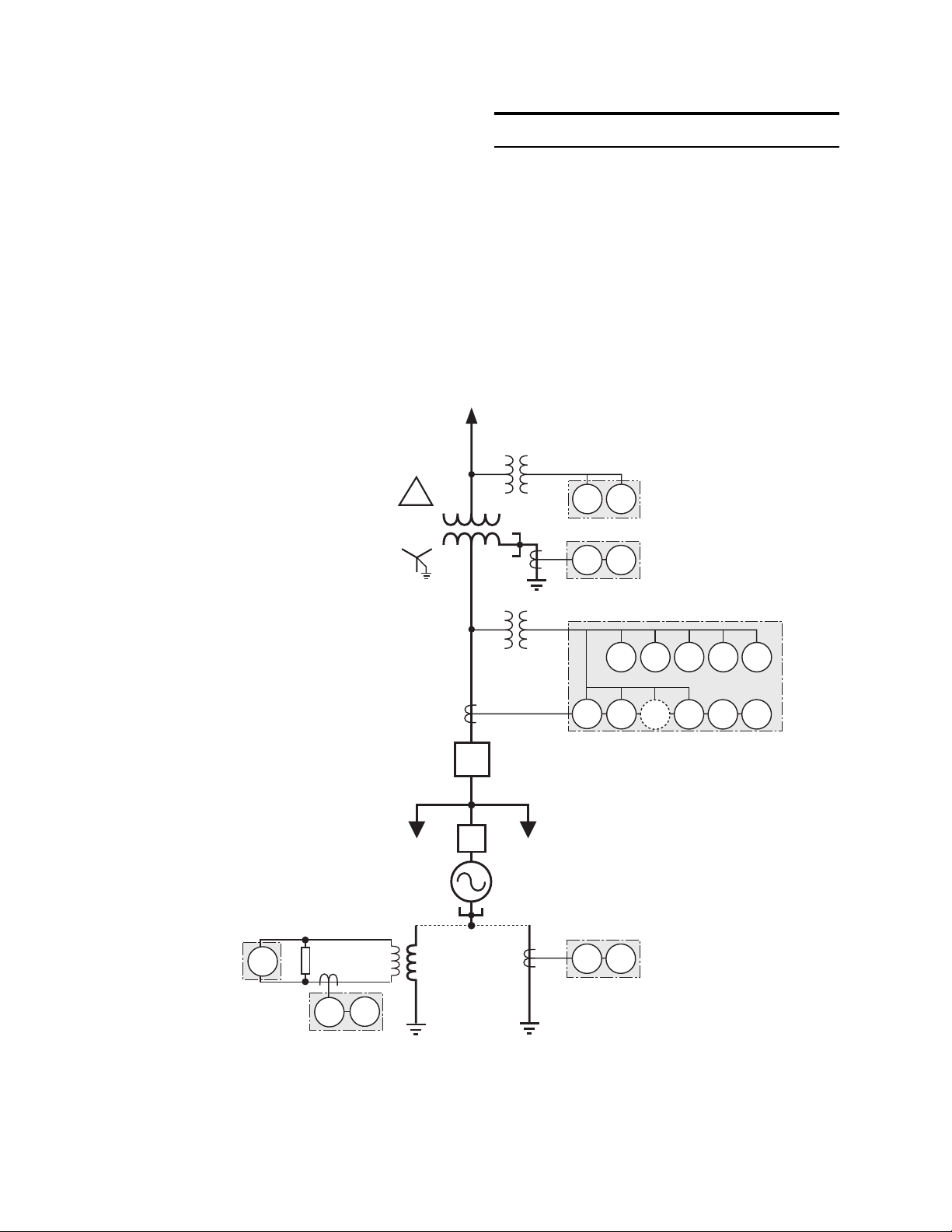
The system one-line diagram shown in Figure 2-1
and the system three-line diagram in Figure 2-2
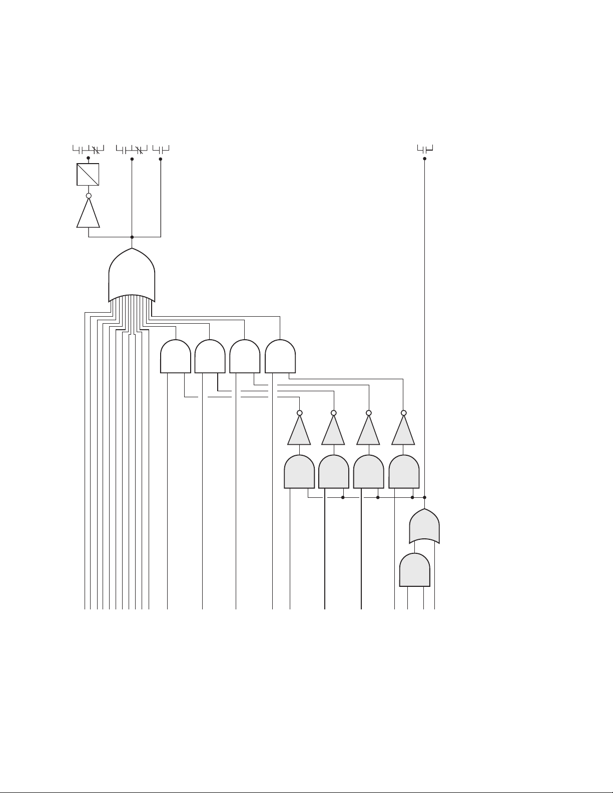
illustrate the typical intertie protection capabilities of the relay. Figure 2-3 illustrates the trip
logic used when the relay is configured for intertie protection.
*
59N27N
➀
50N 51N
➁
**
I
59
67
59
60FL
46
81O81U
50
52I
52G
27
32
51
3
V
➂➄➃
➅
Load Bus
2–4
59N
50N 51N
➀
51N
50N
➁
High-Impedance
Grounding
Low-Impedance
Grounding
Figure 2-1 Intertie Protection –Typical One-Line Diagram
➁
Page 23
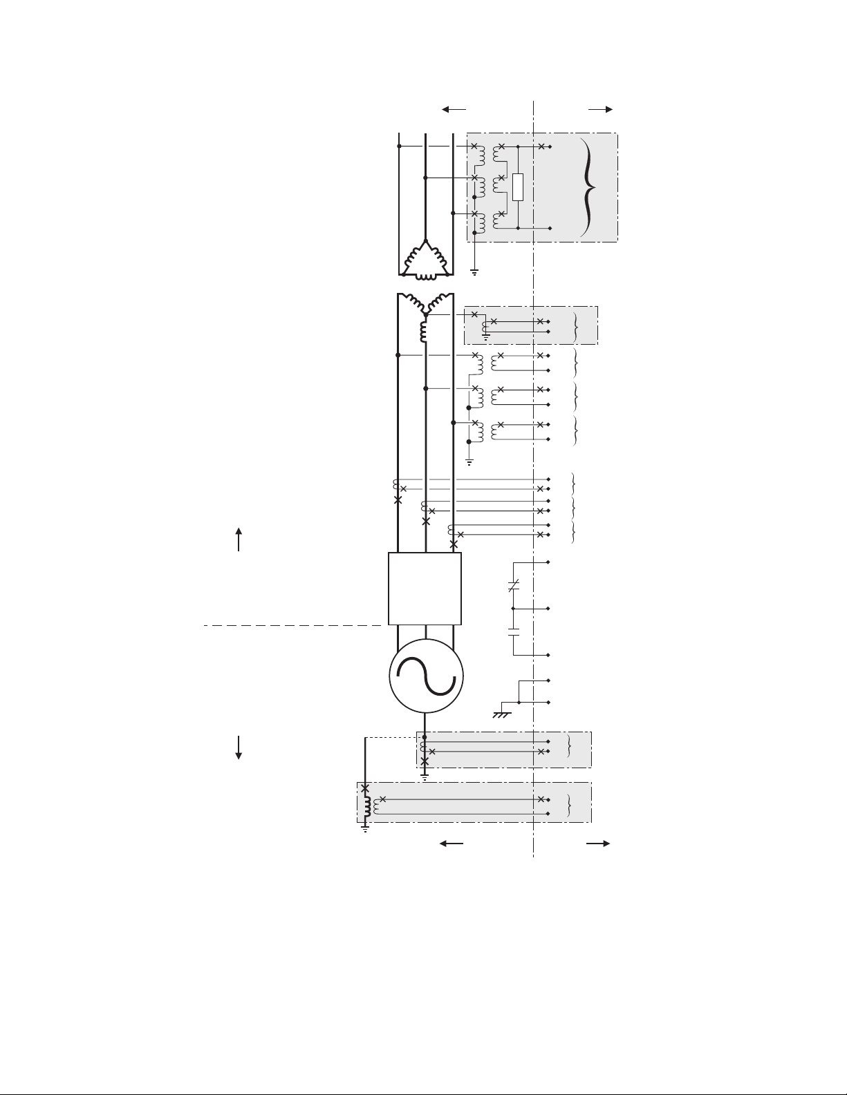
SYSTEM RELAY
Application – 2
Power
Transformer
A
a
acb
19
R
11
12
13
14
15
16
17
18
10
20
6
5
8
7
9
B
C
c
b
➀
V
N
➁
I
N
V
a
V
b
V
c
I
a
I
b
I
c
32
52b Breaker
AC
Circuit
UTILITYGENERATOR
Breaker
52I
Generator
SYSTEM RELAY
n NOTES:
a If voltage is used for generator neutral fault detection, the 59N input is not available for utility ground fault
monitoring at terminals 19 and 20.
b The Neutral Current input can be used either at the transformer neutral or the generator neutral, but not both
simultaneously.
Status Input
52
External Status
Common
33
60 F.L. Input
30
Chassis Ground
24
12
11
19
20
➁
I
N
➀
V
N
Figure 2-2 Intertie Protection–Typical Three-Line Diagram
2–5
Page 24
M-0420 Instruction Book
Trip Output
Trip Annunciate
Reconnect
Enable Output
0
RT
NOT
OR
Output
VT Fuse Loss
Output
AND
AND
AND
AND
NOT
AND
NOT
AND
NOT
AND
NOT
AND
OR
AND
➂
59
59I
59N
27N
81U5050N
51N
81O
67
46
32F
27
32R
➀
51V
➀
➂
➁
should not be enabled. b If 51V blocking is enabled when a blown VT fuse condition is detected, the M-0420
disables 51VC (if VC is enabled) or disables VR of 51VR (keeping the tap setting at the value established for the
rated voltage input). c If 51V is controlled by the directional element of 67, 51V will be blocked when 67 is
60 F.L.
device 60.)
blocked.
2–6
Enable 67 Blocking
Enable 27 Blocking
Enable 32R Blocking
Enable 51V Blocking
Figure 2-3 Intertie Protection–Trip Logic
Internal VT Fuse Loss
Enable Internal VT Fuse Loss
input from supplemental
(External VT fuse loss contact
■ NOTES: a When the high-speed setting has been selected for the 32R or 67 functions, the respective blocking function
Page 25
2.4 Generator Protection
Application – 2
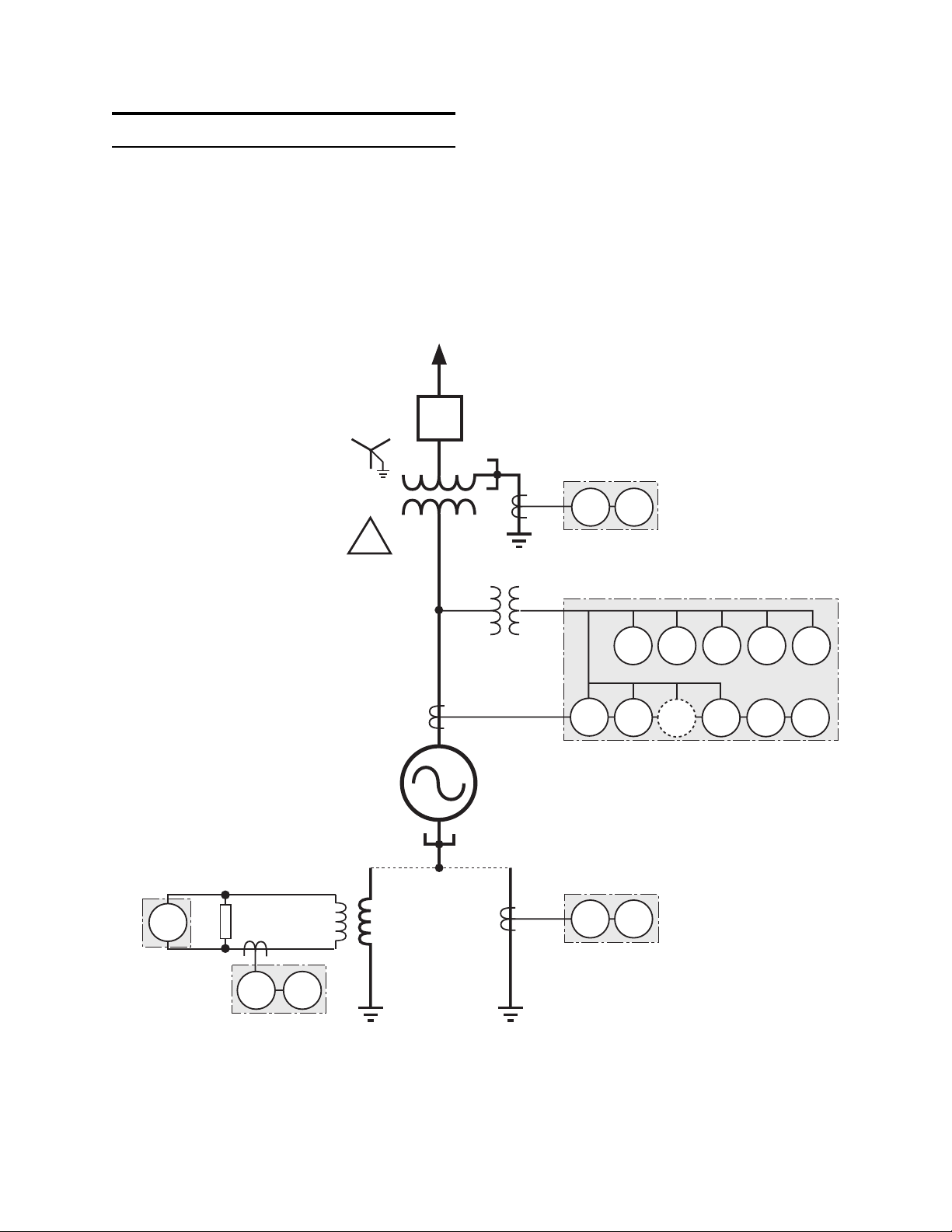
The system one-line diagram shown in Figure
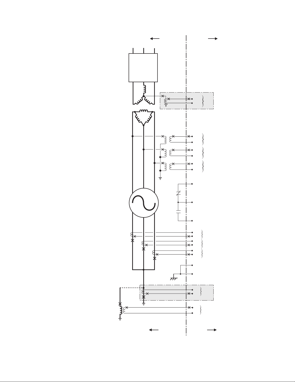
2-4, and the system three-line diagram shown in
Figure 2-5 illustrate the typical generator protection capabilities of the M-0420 Multifunction Protection Relay. Figure 2-6 illustrates the trip logic
used when the relay is configured for generator
Utility System
52
n NOTES:
*
Voltage transformer connection
may be wye, open delta, or delta.
a Since only one neutral current input
is provided, the 50N/51N functions
can be used in one of the locations
shown, but not all simultaneously.
50N/51N can be used in high- or
low-impedance grounding or to
detect ground fault currents on the
grounded wye side of the power
transformer.
b 51V may be either 51VC or 51VR,
with or without directional (67)
control.
c 67 (Phase Directional Overcurrent)
function is optional.
d 60FL VT Fuse Loss detector.
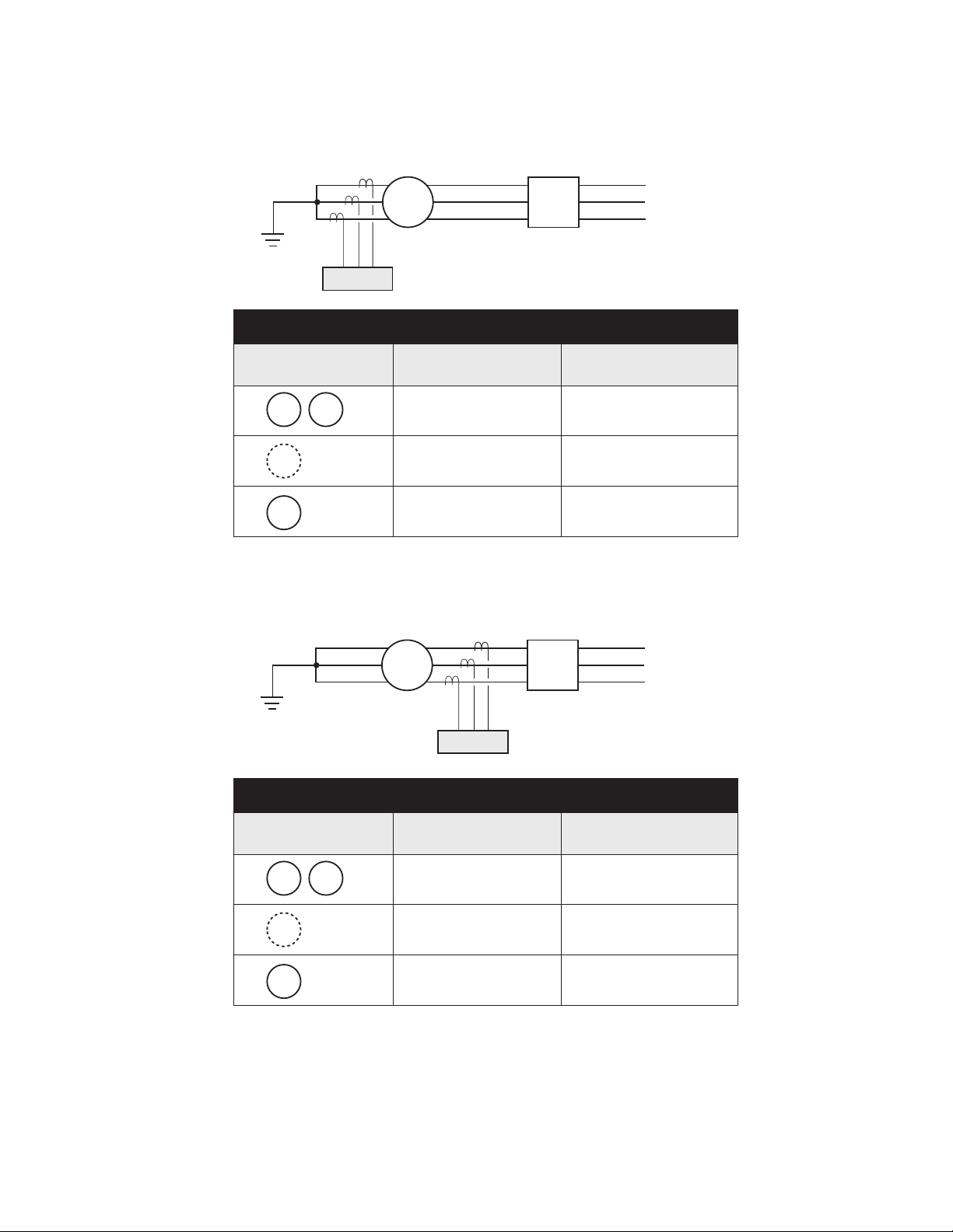
protection. Table 2-1 provides general guidelines
for the placement of current transformers for generator phase-to-phase fault protection.
■ NOTE: These are guidelines only, and may not
apply to all situations.
50N 51N
➀
*
I
59
67
59
60FL
27
32
51
3
V
➁➂➃
46
81O81U
50
59N
51N50N
➀
50N 51N
➀
High-Impedance
Grounding
Low-Impedance
Grounding
Figure 2-4 Generator Protection–Typical One-Line Diagram
2–7
Page 26
M-0420 Instruction Book
Circuit
Breaker
Power
Transformer
n NOTE: a The neutral current input
can be used either at the transformer
neutral or the generator neutral, but
not both simultaneously.
AC
SYSTEM RELAY
52
B
A
a
C
c
b
11
12
13
14
15
16
17
18
➀
I
N
V
a
V
b
V
c
Generator
acb
32
52b Breaker
Status Input
52
External Status
Common
33
60 F.L. Input
6
I
a
5
8
I
b
7
10
I
c
9
30
Chassis Ground
24
12
I
N
11
19
V
N
20
➀
2–8
SYSTEM RELAY
Figure 2-5 Generator Protection—Typical Three-Line Diagram
Page 27
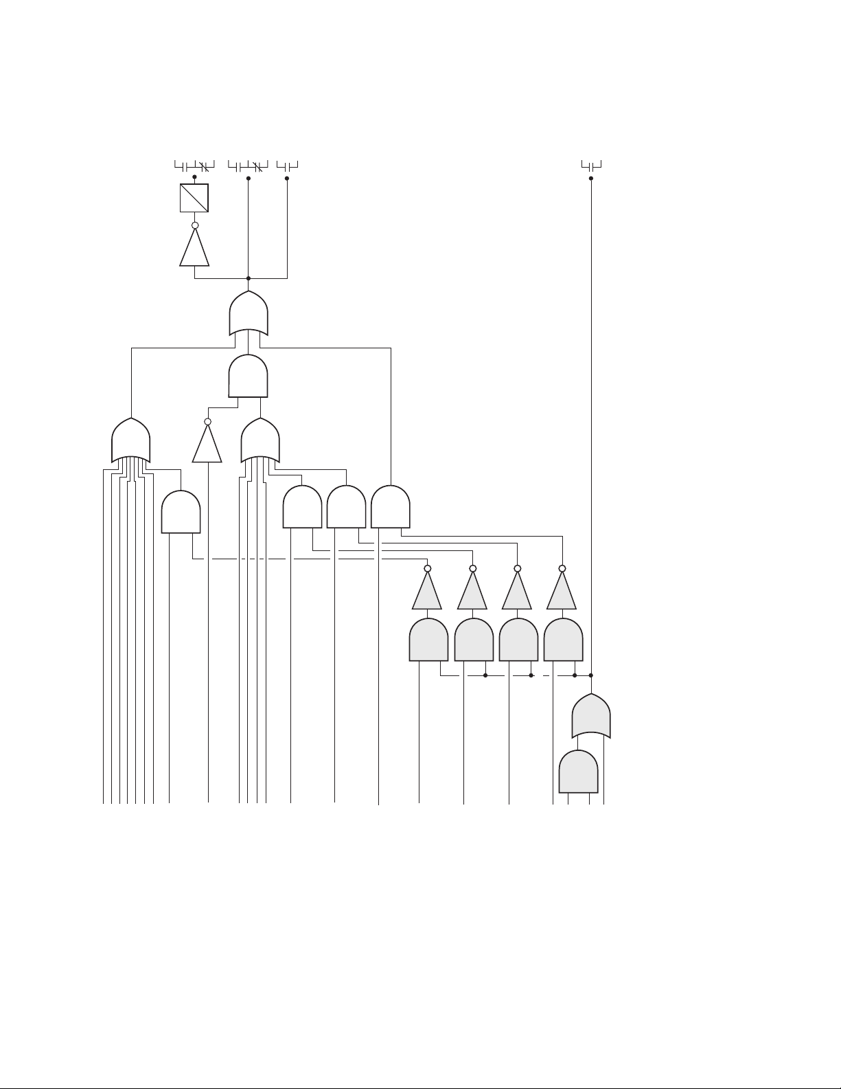
Reconnect
Enable Output
0
RT
NOT
Trip Output
OR
AND
Trip Annunciate
Output
VT Fuse Loss
Output
Application – 2
OR
NOT
AND
OR
AND
AND27AND
NOT
AND
NOT
AND
NOT
AND
NOT
AND
OR
AND
➂
59
59I
59N
67
50
50N
51N
46
52b
breaker
27N
81O
status input
81U
32F
32R
➀
51V
Enable 67 Blocking
➀
Enable 27 Blocking
Enable 32R Blocking
➂
➁
Enable 51V Blocking
Internal VT Fuse Loss
Enable Internal VT Fuse Loss
device 60.)
60 F.L. Input
input from supplementary
(External VT fuse loss contact
should not be enabled. b If 51V blocking is enabled when a blown VT fuse condition is detected, the M-0420
disables 51VC (if VC is enabled) or disables VR of 51VR (keeping the tap setting at the value established for the
rated voltage input). c If 51V is controlled by the directional element of 67, 51V will be blocked when 67 is blocked.
■ NOTES: a When the high-speed setting has been selected for the 32R or 67 functions, the respective blocking function
Figure 2-6 Generator Protection–Trip Logic
2–9
Page 28
M-0420 Instruction Book
CTs on Neutral Side
G
M-0420
Protection Applications — Phase-to-Phase Faults
Protective
Device Function
51
50
VR
*
67
46
Offline
(Synchronizing)
Applicable Protection Applicable Protection
Not Applicable Not Applicable
Applicable Protection Applicable Protection
CTs on Line Side
52
SYSTEM
On-Line
G
M-0420
Protection Applications — Phase-to-Phase Faults
Protective
Device Function
51
50
VR
*
67
46
■ NOTE: The 67 phase directional overcurrent function is optional. Using the 67 function for protec-
tion against inadvertent energizing is applicable to both CT positions.
Offline
(Synchronizing)
Not Applicable
Not Applicable
Not Applicable
52
Applicable Protection
Applicable Protection
(MSA must be set towards
Applicable Protection
SYSTEM
On-Line
generator.)
Table 2-1 Current Transformer Placement Considerations
for Generator Phase-to-Phase Fault Protection
2–10
Page 29
2.5 Setpoints
Application – 2
The M-0420 Multifunction Relay provides
programmable setpoints for each function. Currentrelated functions incorporate instantaneous or
inverse time characteristics consistent with industry
standards. Voltage and frequency functions can
have a magnitude #1 and a magnitude #2 setpoint
in conjunction with a time delay #1 and a time
delay #2 setting.
■ NOTE: Functions with two setpoints are shipped
with the second one disabled. These will not appear on the menu until they have been enabled.
See Chapter 5, Menu Reference.
Over Frequency
Magnitude #1
61.0
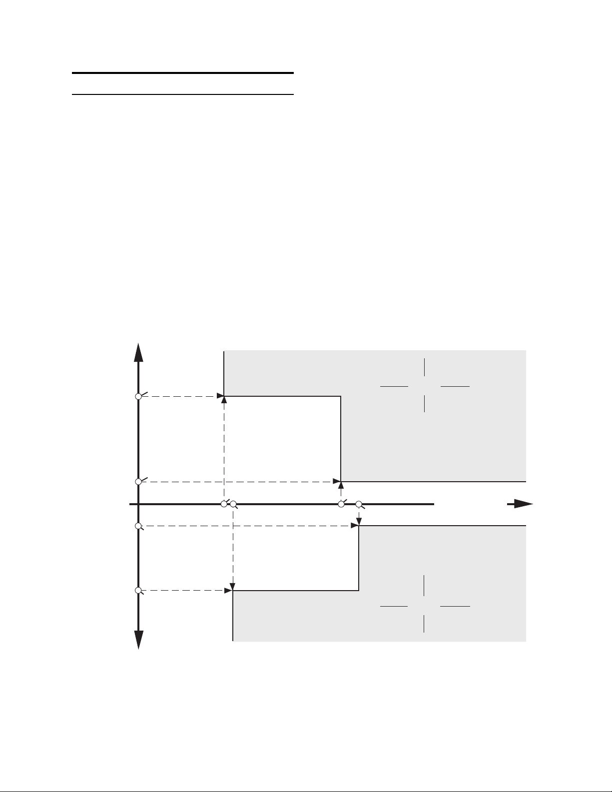
As an example, consider the 81 device. The over
frequency value can be set in the relay from 60.05
to 63.00 Hz in 0.05 Hz increments, and the
associated time delay may be set from the
minimum relay operating time of 2 cycles to 8160
cycles. Specific user requirements may mean that
this function will be programmed, for example, to
trip at 240 cycles if the frequency increases to
60.2 Hz, but trip at 10 cycles at 61 Hz – a first
approximation of an inverse characteristic (shown
in Figure 2-7). As illustrated in this figure, the
under frequency setpoints are independent and
need not mirror the setpoints used for over
frequency.
Trip
60.8
60.6
60.4
Over Frequency (Hz)
60.2
60.0
59.8
59.6
59.4
59.2
Under Frequency (Hz)
59.0
Over Frequency
Magnitude #2
Under Frequency
Magnitude #2
Under Frequency
Magnitude #1
Over Frequency
10
Time Delay #1
15
Under Frequency
Time Delay #1
240
250
Over Frequency
Time Delay #2
Under Frequency
Time Delay #2
Time (cycles)
Trip
Figure 2-7 Example of Trip Characteristics: Over and Under Frequency
2–11
Page 30

M-0420 Instruction Book
2.6 Functions
81O/81U Over Frequency/Under Frequency
When a dispersed source of generation (DSG) is
suddenly islanded, the frequency will quickly shift
from 60.0 Hz (except for the improbable case of
an exact generation and load match), making the
measurement of frequency an excellent means
to detect the island condition. If the only purpose
is to detect the island condition, the frequency
relays 81U and 81O can be set to operate at
59.5 Hz and 60.5 Hz respectively (on a 60 Hz
system) with a time delay of about 6 cycles.
NOITCNUF EGNARTNIOPTES TNEMERCNI
)O18(ycneuqerfrevO
2#,1#edutingaM
A second school of thought, however, advocates
that the DSG should definitely not be severed
from the utility at the slow side while the frequency
remains as high as 59.5 Hz. This concept follows
from the premise that if the drop in frequency is
due to a major loss of system generation, it is
just at this time that all available DSG should be
kept on-line to help avoid a complete system
collapse. If this is the objective, it may be useful
to set one underfrequency characteristic at 57.5
to 58.0 Hz with a very short time delay, but allowing
a higher frequency, say 59.0 Hz, to be maintained
for several seconds.
LAITINI
-
GNITTES
zH00.36ot50.06
)zH00.35ot50.05(
zH50.0zH05.06
2#,1#yaleDemiTselcyc0618ot2elcyc0.1selcyc03
)U18(ycneuqerfrednU
2#,1#edutingaM
zH59.95ot00.35
)zH59.94ot00.34(
zH50.0zH05.95
2#,1#yaleDemiTselcyc0618ot2elcyc0.1selcyc03
-
ehtybdemmargorperlitnuyromemtnioptesnisieulavehT:gnitteSlaitinI
nehwdelbane1#tnioptesylnoevahstnioptesowthtiwsnoitcnuf;rotarepo
.yrotcafmorfdeppihs
Table 2-2 Over (81O) and Under (81U) Frequency Setpoint Ranges
2–12
Page 31

59/27 Overvoltage/Undervoltage
Voltage is also commonly suggested as an efficient
means to protect against islanding. Notably, unless
the DSG includes very high-speed generator
excitation response, the island case where load
is less than generation will result in a rapid rise
of potentially damaging voltage. Except for those
systems prone to ferroresonance, the voltage
waveform will remain essentially sinusoidal, making
the use of rms measurement appropriate for these
functions. An IEEE suggestion is that undervoltage
relays be set at 90% to 95% of nominal voltage
(in accordance with the lower limit allowed for
supply to customers) with a 1 second time delay
to prevent incorrect operation from a voltage dip
caused by an external fault. For instantaneous
Application – 2
overvoltage operation, IEEE suggests that the first
setpoint (with a short time delay) be set at up to
150% of the nominal voltage, and the second
setpoint (with a long time delay) at 106% to 110%
of the nominal voltage to prevent nuisance trips
(
Intertie Protection of Consumer-Owned Sources
of Generation, 3 MVA or Less
88TH0224-6-PWR).
▲ CAUTION: When 69.3 V is chosen for the VT
secondary voltage, 69.3 V is internally converted
to 120 V (1 pu) for all calculations and for setting
and display purposes. For example, if a pickup
of 73 V (1.1 pu) is desired when 69.3 V has been
chosen for the VT secondary voltage, this will be
displayed and entered as 126.4 V (1.1 pu on 120
V base).
; IEEE Publication
NOITCNUF EGNARTNIOPTES TNEMERCNI
LAITINI
-
GNITTES
)95(esahP-3,egatlovrevOSMR
2#,1#edutingaMV002ot01V0.1V231
2#,1#yaleDemiTselcyc0618ot1elcyc0.1selcyc03
)72(esahP-3,egatlovrednUSMR
2#,1#edutingaMV002ot01V0.1V801
2#,1#yaleDemiTselcyc0618ot1elcyc0.1selcyc03
-
ehtybdemmargorperlitnuyromemtnioptesnisieulavehT:gnitteSlaitinI
nehwdelbane1#tnioptesylnoevahstnioptesowthtiwsnoitcnuf;rotarepo
.yrotcafmorfdeppihs
Table 2-3 Overvoltage (59) and Undervoltage (27) Setpoint Ranges
2–13
Page 32

M-0420 Instruction Book
59I Peak Overvoltage
Unless otherwise noted, an overvoltage relay is
presumed to operate based on the rms value of
voltage. There is, however, a system phenomenon
known as ferroresonance that can occur on a
lightly loaded islanded system. As the name
implies, a system experiencing ferroresonance is
in resonance, but the inductance is highly
nonlinear, being variable as the transformer core
cycles in and out of magnetic saturation. At this
time, the voltage waveform will be expected to
be very rich in harmonics, to the extent that it is
possible that the peak voltage of the non-sinusoidal
wave will be dangerously high, even though the
rms value of the same voltage remains in an
acceptable range.
Because it is necessary to describe voltage for
this purpose in terms of the peak value of volt-
age (not rms), it is convenient to define the parameter setpoints in per unit of the peak of the
nominal sinusoidal waveform. Then, with the peak
value of a nominal 120 V sine wave being 120 x
S2 = 170 V, a 1.2 per unit setting would initiate
tripping action at 1.2 x 170 = 204 V, as instantaneously detected. Note that, because of the nonsinusoidal voltage waveform expected, the rms
value of this voltage cannot be so simply calculated as 204 V/S2 = 144 Volts, but may be very
much less than that value. One suggestion is that
this function be set at 1.3 to 1.5 per unit with the
time delay set to operate very quickly, i.e., at
less than 10 cycles of delay.
■ NOTE: When 69.3 V is chosen for the VT sec-
ondary voltage, 1 pu peak voltage is equivalent
to 69.3 x S2 = 98 V.
NOITCNUF EGNARTNIOPTES TNEMERCNI
LAITINI
-
GNITTES
*)I95(egatlovrevOkaeP
2#,1#edutingaMup05.1ot50.1up10.0up01.1
2#,1#yaleDemiTselcyc0618ot1elcyc0.1selcyc03
ecnanoserorrefrofdednetni;esnopseredutingamegatlovsuoenatnatsnI*
.noitcetorp
-
ehtybdemmargorperlitnuyromemtnioptesnisieulavehT:gnitteSlaitinI
nehwdelbane1#tnioptesylnoevahstnioptesowthtiwsnoitcnuf;rotarepo
.yrotcafmorfdeppihs
Table 2-4 Peak Overvoltage (59I) Setpoint Ranges
2–14
Page 33

59N/27N Overvoltage/Undervoltage, Neutral
Circuit or Zero Sequence
These devices may be adapted in various ways
depending upon the location in the circuit and
the protection objective. The 59N device is very
effective in detecting generator ground faults when
generator neutral impedance grounding is used
in conjunction with a distribution transformer. In
such a high-impedance grounding system, ground
faults in the primary system will induce zerosequence voltages at the generator due to
capacitive coupling between the windings of the
unit transformer. If the coupling voltage is
anticipated to be greater than the 59N relay pickup
voltage, a time delay should be used to permit
the primary ground relays to clear high-side faults.
For good fault sensitivity, the pickup of the 59N
function should be about 10 to 16 V. However,
because the third and higher harmonic voltages
that normally appear at the generator neutral can
easily exceed this value, they must be filtered or
the relay otherwise be made insensitive to them.
Additionally, a greater portion of the generator
Application – 2
stator windings can be protected by tuning the
59N function to the fundamental frequency only.
For these reasons, the 59N and 27N functions
respond only to the fundamental frequency
component while rejecting all harmonics. (This is
true regardless of the setting of internal
configuration DIP switch 8.)
Other 27N/59N applications, shown in Figures 2-11
and 2-12, are for detecting ground faults on the
utility side of the power transformer. Protection
schemes are applied based on using one or three
voltage transformers (VT).
▲ CAUTION: When 69.3 V is chosen for the VT
secondary voltage, 69.3 V is internally converted
to 120 V (1 pu) for all calculations and for setting
and display purposes. For example, if a pickup
of 73 V (1.1 pu) is desired when 69.3 V has been
chosen for the VT secondary voltage, this will be
displayed and entered as 126.4 V (1.1 pu on 120
V base).
NOITCNUF EGNARTNIOPTES TNEMERCNI
LAITINI
-
GNITTES
)N95(ecneuqeSoreZrotiucriClartueN,egatlovrevOSMR
2#,1#edutingaMV002ot01V0.1V051
2#,1#yaleDemiTselcyc0618ot1elcyc0.1selcyc03
)N72(ecneuqeSoreZrotiucriClartueN,egatlovrednUSMR
2#,1#edutingaMV002ot01V0.1V06
2#,1#yaleDemiTselcyc0618ot1elcyc0.1selcyc03
-
ehtybdemmargorperlitnuyromemtnioptesnisieulavehT:gnitteSlaitinI
nehwdelbane1#tnioptesylnoevahstnioptesowthtiwsnoitcnuf;rotarepo
.yrotcafmorfdeppihs
Table 2-5 Overvoltage (59N) and Undervoltage (27N) Setpoint Ranges
2–15
Page 34
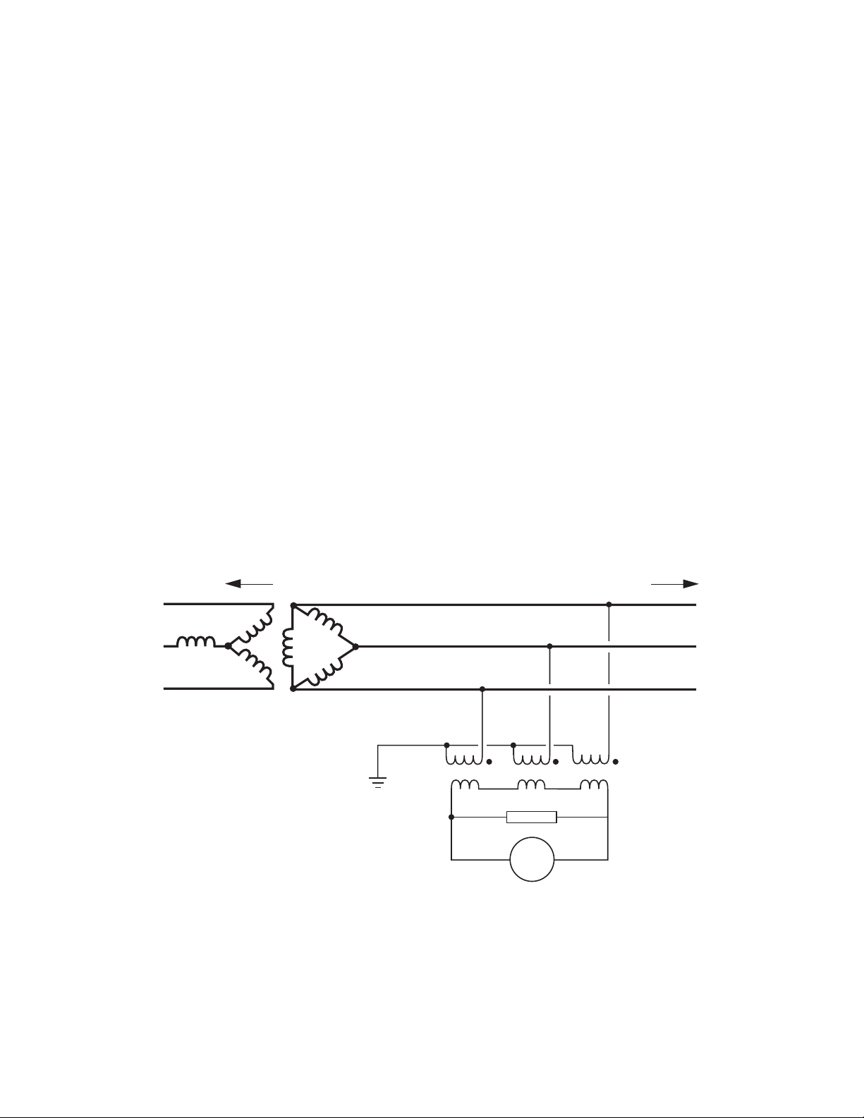
M-0420 Instruction Book
Ground Fault Detection Using 59N and
Broken-Delta VTs
The 59N may be used to detect system phase
voltage unbalance in conjunction with three VTs.
To do so, the VT secondaries are connected in
“broken” delta; i.e. they are in delta except that
one corner is open and the 59N device is inserted, as illustrated in Figure 2-8.
In this case, voltage at 59N in Figure 2-8 will be
zero so long as the three-phase voltages are
balanced, but will rise above zero with any zerosequence unbalanced condition, as will be
expected with any real-world utility ground fault.
When the relay burden is small, the transformers
in this scheme will be subject to ferroresonance
and high voltage oscillations unless a shunt resistor is used. The shunt resistor will damp high
transient voltage oscillations and will usually hold
peak values to less than twice normal crest voltage to ground. (
inghouse Electric Corporation, 1982
Applied Protective Relaying, West-
.)
To Dispersed Source of
Generation (DSG)
c
b
a
Power
Transformer
RESISTOR
59N
To
Utility
C
B
A
Figure 2-8 Ground Fault Detection Using 59N and Broken-Delta VTs
2–16
Page 35
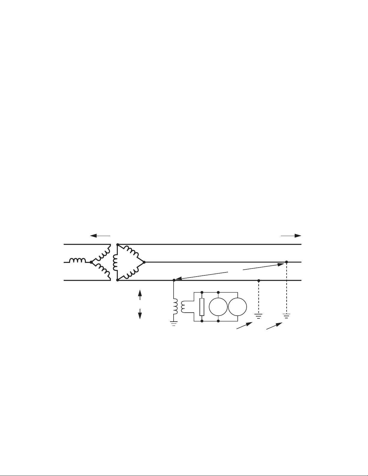
Ground Fault Detection Using 27N and 59N
with One VT
An alternate, but not recommended, scheme uses
the 27N and 59N devices with one VT rated for
line-to-line voltage, but connected from any one
phase to ground as shown in Figure 2-9. This
scheme will detect the most common line-to-ground
faults in the following manner:
1. A fault on the phase that includes the VT
will pull that phase voltage low and initiate
operation of the 27N device.
2. A fault on either phase without the VT will
result in line-to-line voltage (or S3 x normal
line-to-neutral voltage) appearing at the VT,
initiating operation of the 59N.
Application – 2
For this scheme to work, the capacitance to ground
of the lines must be fairly closely balanced and
high enough to keep the neutral of the system at
close to ground potential. The shunt resistor helps
to minimize the chance of ferroresonance or neutral
inversion. (
house Electric Corporation, 1982
Applied Protective Relaying, Westing-
.)
▲ CAUTION: This scheme should be used with
caution since it can result in high overvoltages
due to ferroresonance and neutral inversion.
To Dispersed Source of
Generation (DSG)
c
b
V
L-L
a
Power
Transformer
V
RESISTOR
Fault on phase 'a'
27N detects
undervoltage
59N27N
Fault on phase 'b'
V=0
To
Utility
V=V
L-L
59N detects
overvoltage
C
B
A
Figure 2-9 Ground Fault Detection Using 27N and 59N with One VT
2–17
Page 36

M-0420 Instruction Book
51V Inverse Time Overcurrent, Three-Phase
with Voltage Control or Voltage Restraint
Time-overcurrent relays, one per phase, are basic
to any protection scheme. This is the main device
used to trip circuits selectively and to timecoordinate them with other up- or downstream
devices. For this function, four complete series
of inverse time tripping characteristics are included,
based on the ABB CO and COV curves. This is
accomplished in a way that allows the protection
engineer to use the same descriptions and
nomenclature which are traditionally used with
electromechanical relays. Thus, the four curve
families to be chosen are definite time, inverse,
very inverse or extremely inverse, which relate
to the degree of slope of the basic characteristic
curves. In the menu, these are abbreviated as
DEF, INV, VINV, and EINV. Within each family,
the operator selects time dial setting and tap setting
through the menu, just as one would through
electromechanical means.
The curves available for use are shown in Figures
2-10 through 2-13. They cover a range of from
1.5 to 20 times the tap setting. An additional onecycle time delay should be added to these curves
in order to obtain the relay operating time. For
currents beyond 20 times the tap setting, the relay
operating time will be the same as the time for
20 times the tap setting; i.e., the relay operates
at definite minimum time. The particular settings
will be made by information from short-circuit (fault)
studies and knowledge of the coordination
requirements with other devices in the system
that respond to time overcurrent.
When voltage restraint is selected, the tap setting
of the 51VR is modified continuously according
to the voltage inputs as shown in Figure 2-14.
The relay continues to operate independently of
current decrement in the machine. The voltage
restraint function is well-suited to small generators
with relatively short time constants. (Voltage
restraint is disabled as shipped from the factory.)
When the generator is connected to the system
through a delta/wye transformer, proper voltages
(equivalent to the high-side of the transformer)
should be used for the 51VR or 51VC element.
The relay can internally determine the equivalent
high-side voltages of the delta/wye unit transformer,
saving auxiliary instrument transformers. The
voltage-current pairs used are shown in Table
2-6.
▲ CAUTION: When 69.3 V is chosen for the
VT secondary voltage, 69.3 V is internally converted to 120 V (1 pu) for all calculations and for
setting and display purposes. For example, if a
pickup of 73 V (1.1 pu) is desired when 69.3 V
has been chosen for the VT secondary voltage,
this will be displayed and entered as 126.4 V (1.1
pu on 120 V base).
100
75
Tap Setting as %
of Tap Setting at
Rated Voltage
50
25
A unique feature of this relay concerns the
calculation of the current used for tripping. The
current is derived from an rms calculation, but,
by user selection, will be computed based on either
inclusion or exclusion of the contribution of
harmonics to the value. Since it is not well
established by the industry whether the calculation
should be based simply upon the fundamental
frequency component or a broader frequency
range, a simple DIP switch setting (No. 8) allows
the operator to select either one.
The inverse time overcurrent function can be
voltage controlled (VC) or voltage restrained (VR).
2–18
0
0
Input Voltage (% of rated voltage)
5025 75 100
Figure 2-10 Voltage Restraint (51VR)
Characteristic
Page 37
Application – 2
egatloV
tnerruC
N-LL-LN-LL-L
I
A
I
B
I
C
For voltage controlled operation, the function is
not active unless the voltage is below the voltage
control setpoint, which can be used to help confirm
that the overcurrent is due to a system fault. When
applied, most users will set voltage control in the
range of 0.7 to 0.9 per unit rms voltage. (Voltage
control is disabled as shipped from the factory.
The initial setting of 1.1 pu also effectively disables
this function.)
V(AV-C/) 53 V
V(BV-A/) 53V
V(CV-B/) 53 V
BA
CB
AC
Table 2-6 Delta/Wye Transformer Voltage-Current Pairs
detcennoCyltceriDrotareneG
hguorhTdetcennoCrotareneG
remrofsnarTeyW/atleD
egatloV
tnerruC
I
A
I
B
I
C
If the relay is equipped with the optional phase
directional overcurrent function (67), the 51V
element can be controlled by it, thereby realizing
a directional inverse time overcurrent function.
The various features of the 51V function, such
as voltage control, voltage restraint, voltage
transformations (for delta-wye unit transformers),
and directional control can be programmed by
the operator.
V
V
V
V(
V-
A
B
C
BA
V(
CB
V(
AC
/) 53
AC
V-
/) 53
BA
V-
/) 53
CB
NOITCNUF EGNARTNIOPTES TNEMERCNI
LAITINI
-
GNITTES
tniartseRegatloVdnalortnoCegatloVhtiwesahP-3,tnerrucrevOemiTesrevnI
)V15(
yreV,esrevnI,etinifeD
sevruCcitsiretcarahC
ylemertxE,esrevnI
esrevnIyreV
esrevnI
A54.1ot05.0
gnitteSpaT
A09.2ot05.1
A08.5ot00.3
A00.21ot00.6
A50.0
A01.0
A02.0
A0.6
A05.0
gnitteSlaiDemiT0.11ot5.01.00.5
)CV(lortnoCegatloV
ro
)RV(tniartseRegatloV
V002ot01
)up76.1ot80.0(
V1
tniartseRraeniL
V231
)up1.1(
.yrotcafmorfdeppihsnehwdelbasideratniartseRdnalortnoCegatloV
-
ehtybdemmargorperlitnuyromemtnioptesnisieulavehT:gnitteSlaitinI
.rotarepo
Table 2-7 Inverse Time Overcurrent with
Voltage Control/Voltage Restraint (51VC/VR) Setpoint Ranges
2–19
Page 38
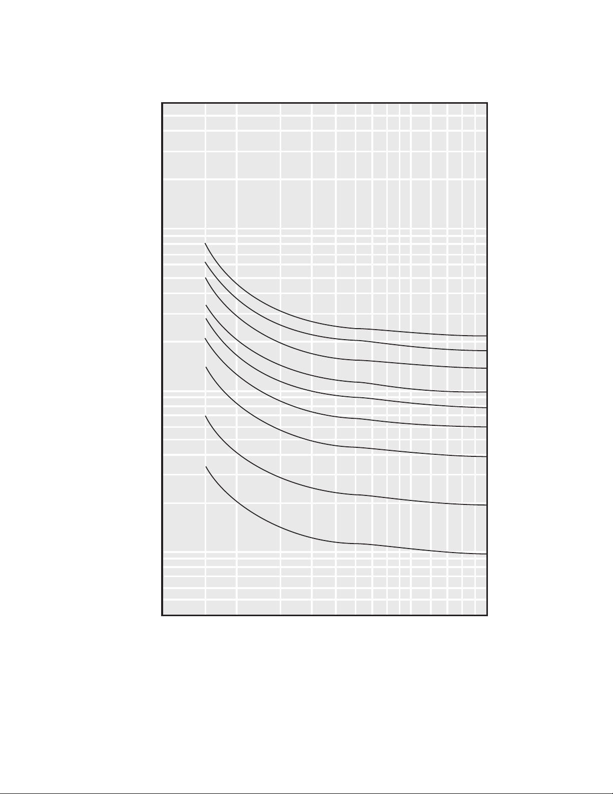
M-0420 Instruction Book
60
40
30
20
10
6
4
Time
(Seconds)
1.0
0.6
0.4
0.3
0.2
0.1
0.06
3
2
Time
Dial
11
9
7
5
4
3
2
1
0.5
0.04
1 1.5 2 3 4 5 6 7 8 9 10 12 14 16 1820
Current in Multiples of Tap Setting
■ NOTE: An additional one-cycle time delay should be added to these curves in order to obtain the
relay operating time.
Figure 2-11 Definite Time Overcurrent Curve
2–20
Page 39
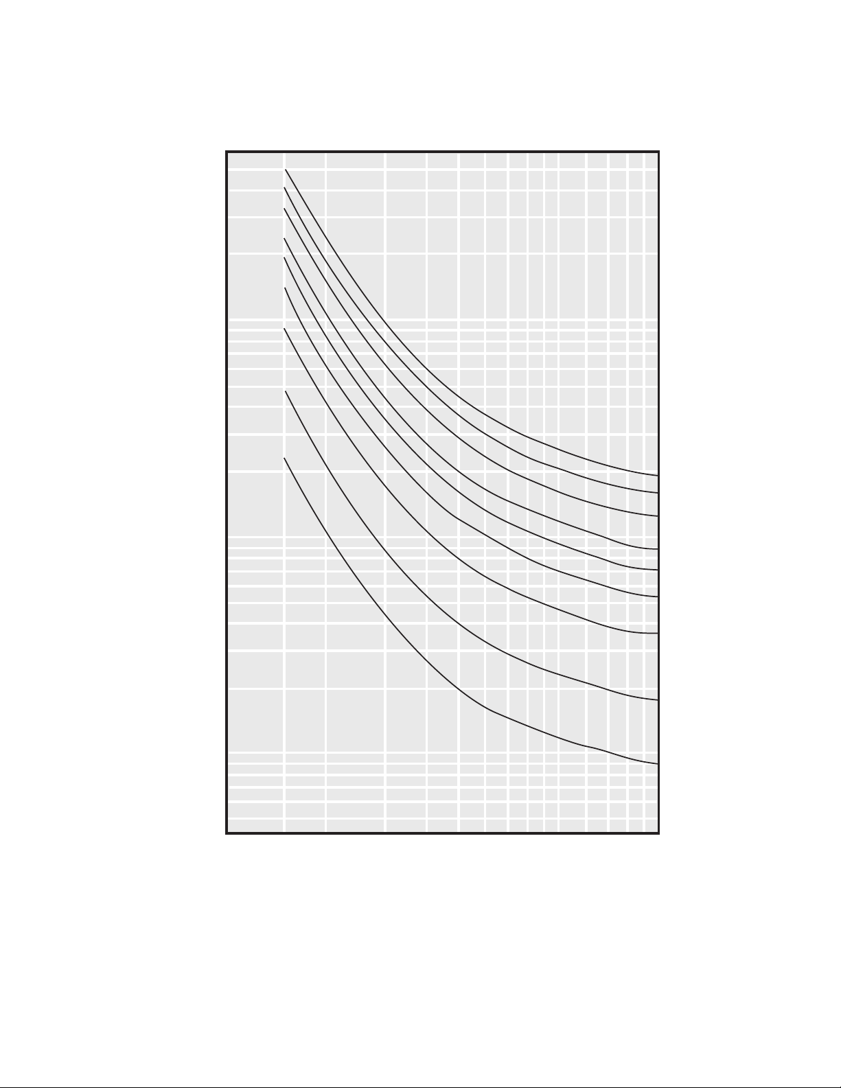
60
40
30
20
10
Application – 2
6
4
Time
(Seconds)
1.0
0.6
0.4
0.3
0.2
0.1
0.06
3
2
Time
Dial
11
9
7
5
4
3
2
1
0.5
0.04
1 1.5 2 3 4 5 6 7 8 9 10 12 14 16 18 20
Current in Multiples of Tap Setting
■ NOTE: An additional one-cycle time delay should be added to these curves in order to obtain the
relay operating time.
Figure 2-12 Inverse Time Overcurrent Curve
2–21
Page 40
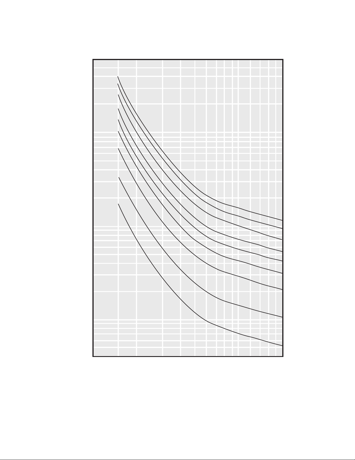
M-0420 Instruction Book
60
40
30
20
10
6
4
3
Time
(Seconds)
2
1.0
0.6
0.4
0.3
0.2
0.1
0.06
0.04
1 1.5 2 3 4 5 6 7 8 9 10 12 14 16 18 20
Time
Dial
11
9
7
5
4
3
2
1
0.5
Current in Multiples of Tap Setting
■ NOTE: An additional one-cycle time delay should be added to these curves in order to obtain the
relay operating time.
Figure 2-13 Very Inverse Time Overcurrent Curve
2–22
Page 41
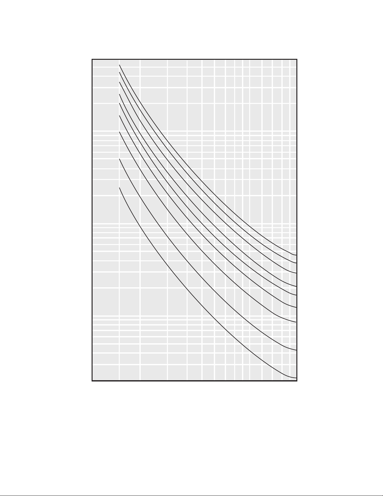
60
40
30
20
10
Application – 2
6
4
3
2
Time
(Seconds)
0.06
0.04
0.03
0.02
1.0
0.6
0.4
0.3
0.2
0.1
1 1.5 2 3 4
Time
Dial
11
9
7
5
4
3
2
1
0.5
6
5
891012 14 16 18 20
7
Current in Multiples of Tap Setting
■ NOTE: An additional one-cycle time delay should be added to these curves in order to obtain the
relay operating time.
Figure 2-14 Extremely Inverse Time Overcurrent Curve
2–23
Page 42

M-0420 Instruction Book
51N Inverse Time Overcurrent, Neutral
Circuit
This is identical in function to 51V except that,
since it is intended for use in the neutral, it will
operate by detecting zero sequence current that
flows during ground faults, and can usually be
set to a more sensitive value than those on the
individual phases. (Voltage control or voltage restraint are not provided in the neutral circuit since
they are not needed.) When used for generator
ground fault protection, 51N provides alternative
or backup ground-fault protection to 59N. This
relay must be set above the maximum zero sequence current that normally flows in the generator neutral. A typical setting would be 1.5 to 2
times the expected maximum zero sequence current value.
If the 51N function is not used at the generator
neutral circuit, it can be used to detect ground
faults on the system by monitoring the current
through the ground connection of a wye-connected
power transformer.
NOITCNUF EGNARTNIOPTES TNEMERCNI
LAITINI
-
GNITTES
)N15(lartueN,tnerrucrevOemiTesrevnI
yreV,esrevnI,etinifeD
sevruCcitsiretcarahC
ylemertxE,esrevnI
esrevnIyreV
esrevnI
A54.1ot05.0
gnitteSpaT
A09.2ot05.1
A08.5ot00.3
A00.21ot00.6
A50.0
A01.0
A02.0
A0.6
A05.0
gnitteSlaiDemiT0.11ot5.01.00.5
-
ehtybdemmargorperlitnuyromemtnioptesnisieulavehT:gnitteSlaitinI
.rotarepo
Table 2-8 Inverse Time Overcurrent Neutral (51N) Setpoint Ranges
2–24
Page 43

50/50N Instantaneous Overcurrent, ThreePhase and Neutral Circuits
The instantaneous phase (50) and neutral
overcurrent (50N) functions provide fast tripping
times for high fault currents. The settings for 50
and 50N should be chosen such that they will
not respond to faults on the adjacent system.
Similar to 51N, the 50N function can also be applied
either at the generator neutral or transformer
neutral.
noitcnuF egnaRtniopteS tnemercnI gnitteSlaitinI
edutingaM*A0.042ot0.1A1.0A0.01
Application – 2
)05(esahP-3,tnerrucrevOsuoenatnatsnI
emiTpirT
esnopseR
.V15rofnesohcegnareht
edutingaM*A0.042ot0.1A1.0A0.01
emiTpirT
esnopseR
.N15ybnesohcegnar
.yrotcafmorfdeppihs
mumixamselcyc2
)N05(lartueN,tnerrucrevOsuoenatnatsnI
mumixamselcyc2
Table 2-9 Instantaneous Overcurrent (50) and
Instantaneous Overcurrent (50N) Neutral Setpoint Ranges
rofgnittespattnerrucrevoesahpmumixamehtsemit02deecxeottoN*
ehtrofgnittespattnerrucrevoesahpmumixamehtsemit02deecxeottoN*
ehtybdemmargorperlitnuyromemtnioptesnisieulavehT:gnitteSlaitinI
nehwdelbane1#tnioptesylnoevahstnioptesowthtiwsnoitcnuf;rotarepo
2–25
Page 44

M-0420 Instruction Book
46 Negative Sequence Overcurrent
Unbalanced faults and other system conditions
can cause unbalanced three-phase currents in
the generator. The negative sequence components
of these currents cause double-frequency currents
in the rotor that can lead to severe overheating
and damage. The negative sequence overcurrent
function is set to operate before the specified limit
for the machine is reached. As established by
the ANSI standards, limits are expressed as I
where I2 is the negative sequence current in
multiples of the tap setting, “t” is the operating
time of the negative sequence relay element in
seconds, and K (the time dial setting) is a constant
established by the machine design.
2
2
t=K,
The negative sequence overcurrent function has
a tap setting variable from 1 A to 5 A and a pickup setting variable from 5% to 100%. Also, the
value of K can vary from 1 to 95, making this
function suitable for any generator size.
The minimum delay for this function is factory
set at 12 cycles to avoid nuisance tripping. The
maximum delay can be set by the user to reduce
the tripping times for modest imbalances. An
important feature that helps protect the generator
from damage due to recurring imbalances is a
linear reset characteristic: when I2 decreases below
the pickup value, the trip timer takes 4 minutes
to reset from its 100% trip level. Figure 2-15
illustrates the inverse time characteristic of the
negative sequence current function.
NOITCNUF EGNARTNIOPTES TNEMERCNI
LAITINI
-
GNITTES
)64(tnerrucrevOecneuqeSevitageN
gnitteSpaTA0.5ot0.1A1.0A0.5
fo%sapukciP
gnitteSpaT
%001ot5%1%05
gnitteSlaiDemiT59ot10.10.52
mumixaMetinifeD
pirTotemiT
-
selcyc000,06ot006selcyc5selcyc000,01
ehtybdemmargorperlitnuyromemtnioptesnisieulavehT:gnitteSlaitinI
nehwdelbane1#tnioptesylnoevahstnioptesowthtiwsnoitcnuf;rotarepo
.yrotcafmorfdeppihs
Table 2-10 Negative Sequence Overcurrent (46) Setpoint Ranges
2–26
Page 45
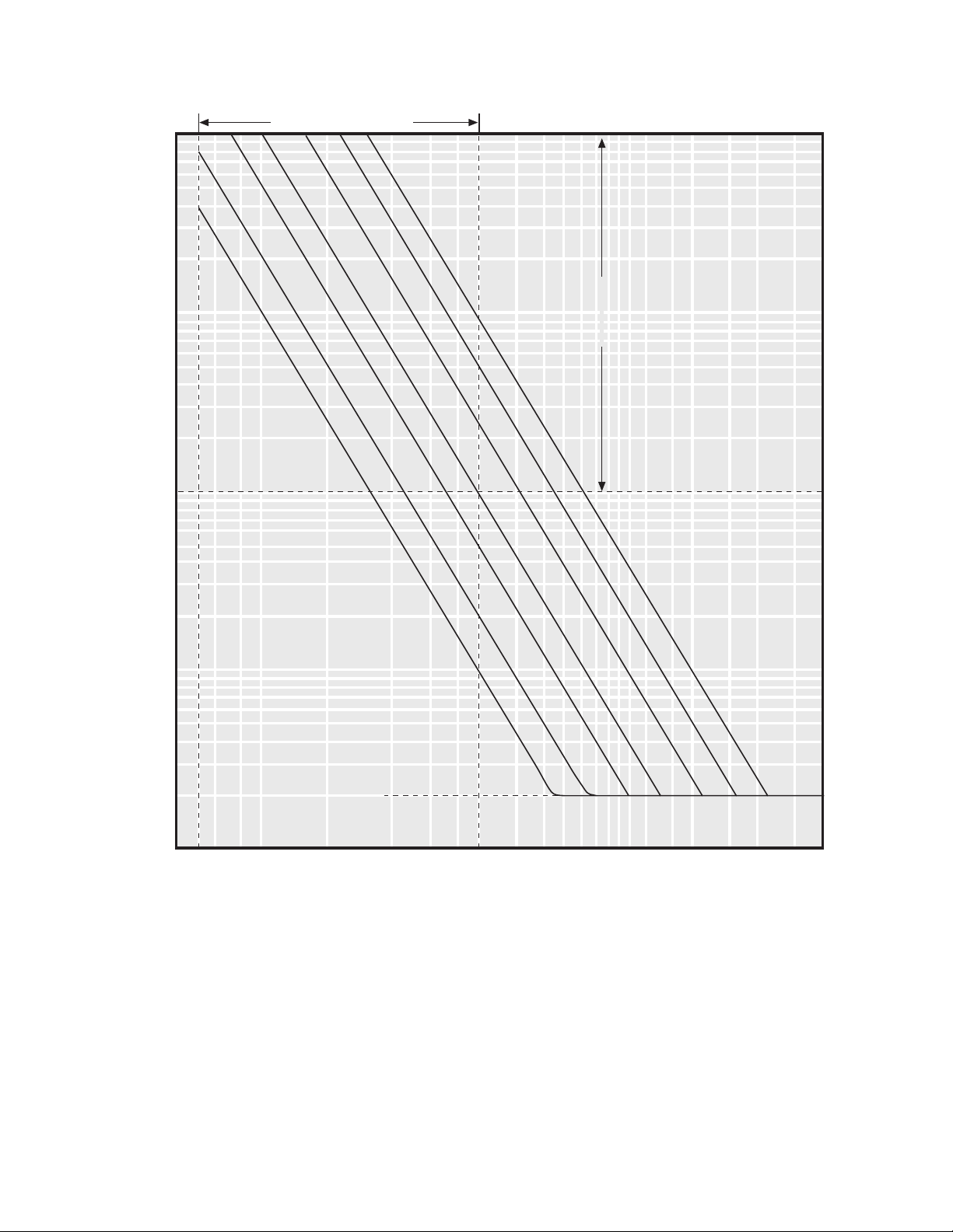
Application – 2
1000
800
600
400
200
100
80
60
40
20
10
8
Time (Seconds)
6
4
Pickup Setting Range
2
I
t = K
2
Definite
Maximum
Time Setting
Range
2
K
1
0.6
0.4
0.2
0.1
4
5 6 8 10 20 40 60 80 100 150 200 300 400 500
Definite
Minimum
Time
10
5
2
1
600 800 1000 2000 40001500 3000
95
50
25
Negative Sequence Current in Percent of Tap Setting
■ NOTE: These curves are valid only for cases where the phase current is less than 30 A (A/D
converter full scale). When the phase current exceeds 30 A, the actual times will be longer than the
ones shown here.
Figure 2-15 Negative Sequence Overcurrent Inverse Time Characteristic
2–27
Page 46
M-0420 Instruction Book
32 Directional Power, Three-Phase
The implementation of the directional power function is straightforward, issuing a trip command
when the magnitude of the power flow (in either
direction as selected) exceeds the setpoint for
the prescribed time. The forward and reverse
power functions can be individually adjusted to
trip when the total three-phase power is in the
range of 0.02 pu to 3.0 pu.
The reverse power function has a single-phase
option that, when selected, can detect reversal
of power in any one phase. (This function is
available only with the line-to-neutral voltage option
selected on the internal configuration DIP switch.)
For generator protection, with VT and CT
connections as illustrated in Figure 2-5, reverse
power is defined as power flow into the generator,
forward power as power flow out. This function
provides protection against generator motoring
(power flowing into the generator). For
interconnection protection, with VT and CT
connections as illustrated in Figure 2-2, reverse
power is defined as power flow into the generator/
customer, forward power as power flow to the
utility.
▲ CAUTION: Proper CT polarity is important in
defining the direction of power flow.
The minimum inherent time delay of the relay to
a reversal of power is 0.75 cycle (selected by
choosing the high-speed setting), and may be
adjusted by the user up to 8160 cycles of intentional
delay.
)up1(serepma-tlovesaB=5 Vx3
=5 5x021x3=5 5x3.96x3
Line-to-Neutral Voltage Input Option
The forward power function and the display of
real and reactive power use three-phase voltamperes as the base:
The base volt-amperes per unit for line-to-line and
line-to-neutral operation (selected via the internal
configuration DIP switch) are derived as follows.
These volt-amperes are used as the base value
(1 pu) for forward and reverse power relay
functions and for display of real and reactive power.
noitpOtupnIegatloVeniL-ot-eniL
sTVyradnocesV021sTVyradnocesV3.96
LIxL
=5 Vx3
LIxL
AV9301=AV006=
2–28
)up1(serepma-tlovesaBVx3=
sTVyradnocesV021sTVyradnocesV3.96
Ix
ESAHP
ESAHP
5x021x3=5x3.96x3=
AV0081=AV9301=
noitpOtupnIegatloVlartueN-ot-eniL
Vx3=
Ix
ESAHP
ESAHP
Page 47
Application – 2
The reverse power function has single-phase/threephase options. The base volt-amperes (1 pu) for
these options are as follows:
Three-phase (line-to-line voltage input) reverse
power base volt-amperes:
rewoPesreveResahP-eerhT
sTVyradnocesV021sTVyradnocesV3.96
AV0081=/0081= 5 AV9301=3
noitcnuF egnaRtniopteS tnemercnI gnitteSlaitinI
)23(esahP-3,rewoPlanoitceriD
rewoPdrawroF
edutingaMwolF
Single-phase (line-to-neutral voltage input) reverse
power base volt-amperes:
rewoPesreveResahP-elgniS
sTVyradnocesV021sTVyradnocesV3.96
AV006=/006= 5 AV643=3
up0.3ot20.0 up10.0 up0.3
2#,1#yaleDemiTselcyc0618ot1elcyc0.1selcyc03
rewoPesreveR
edutingaMwolF
up0.3ot20.0 up10.0 up0.3
*yaleDemiTselcyc0618ot1elcyc0.1selcyc03
57.0=emitesnopser;yaledlanoitnetnionsahgnittesdeeps-hgih,yaleDemiT*
elcyc K .elcyc5.0
Table 2-11 Directional Power (32) Setpoint Ranges
67 Phase Directional Overcurrent Option
For intertie protection applications, the phase directional overcurrent relay allows greater selectivity for
utility system faults, since the directional element can be set to look toward the utility system. As a
generator protection relay, the 67 function, looking into the generator, can provide protection for accidental
energizing of the generator on turning gear. When line-side CT inputs are used, this function can also
provide high-speed protection for generator winding faults. However, with line-side CTs, the protection
2–29
Page 48

M-0420 Instruction Book
for winding faults during off-line operation (when
the breaker is open) is not available from the 51V,
50, 46, or 67 functions.
A single directional element is used to provide
directional discrimination for all types of phaseto-phase and three-phase faults. The directional
element is polarized from positive sequence
voltage and positive sequence current. In order
to obtain maximum sensitivity for fault currents,
the directional element is provided with a maximum
sensitivity angle adjustment (MSA). The directional
element is equipped with a prefault voltage memory
of eight cycles to provide correct directional
discrimination for bolted three-phase faults.
Examples of the tripping and blocking directions
of the directional element are shown in Figure
2-16.
NOITCNUF EGNARTNIOPTES TNEMERCNI
LAITINI
-
GNITTES
)76(tnerrucrevOlanoitceriDesahP
tnemelEtnerrucrevO
edutingaMA*042ot1A1.0A0.01
**yaleDemiTselcyc0618ot1elcyc0.1selcyc03
tnemelElanoitceriD
ytivitisneSmumixaM
)ASM(elgnA)euqroT(
o
0
o
953ot
o
1
o
58
ASMtaytivitisneS)ecneuqesevitisop(AV5.0
yromeMtluaferP)egatlovecneuqesevitisop(selcyc8
seititnauQgniziraloP.tnerrucecneuqesevitisopdnaegatlovecneuqesevitisoP
-3ehthcihwotniegnarehtfognittespatmumixamehtsemit02deecxeottoN*
.sllafV15rofnesohcgnittespattnerrucrevoesahp
57.0=emitesnopser;yaledlanoitnetnionsahgnittesdeepshgiH** K .elcyc5.0
-
ehtybdemmargorperlitnuyromemtnioptesnisieulavehT:gnitteSlaitinI
deppihsnehwdelbane1#tnioptesylnoevahstnioptesowthtiwsnoitcnuf;rotarepo
.yrotcafmorf
2–30
Table 2-12 Phase Directional Overcurrent (67) Setpoint Ranges
Page 49
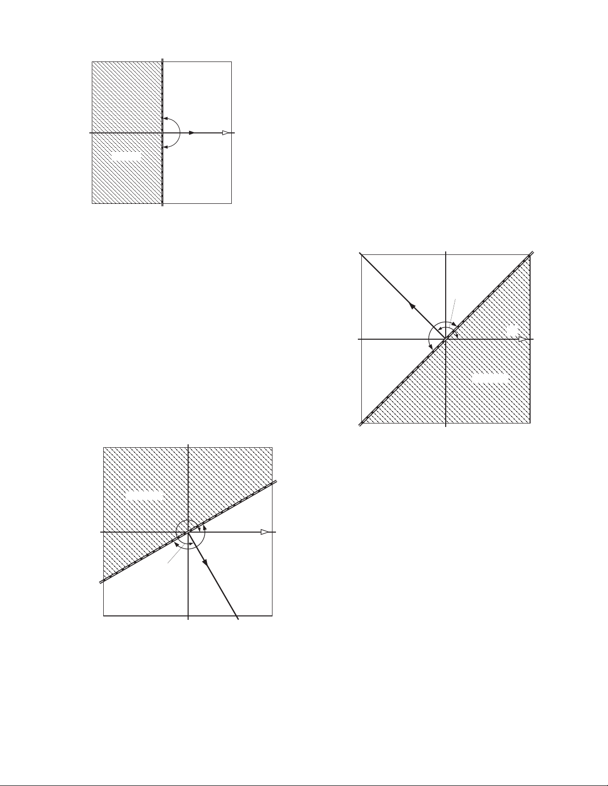
Application – 2
o
90
TRIPPING
180
I
o
BLOCKING
1
V
1
Maximum
Sensitivity Line
o
0
MSA=0°
Zero Sensitivity Line
o
270
(-90O)
Maximum
Sensitivity Line
TRIPPING
I
MSA=135°
MSA = 135°
1
V
1
BLOCKING
Zero Sensitivity Line
BLOCKING
V
1
I
1
Zero
Sensitivity
Line
MSA = 300°
TRIPPING
Maximum
Sensitivity Line
MSA=300°
■ NOTE: V1=Positive Sequence Voltage; I1=Positive Sequence Line Current (at MSA). For forward
power, unity power factor condition V1 and I1 are in-phase both for line-to-ground and line-to-line VT
input conditions (with line-to-line VTs, thirty degrees phase shift is corrected internally in the software).
Figure 2-16 Phase Directional Overcurrent (67) Trip Characteristics
2–31
Page 50

M-0420 Instruction Book
79 Reconnect Time Delay
The reconnect relay is a permissive output that
may be set to close from 1 to 8160 cycles after
all parameters are within limits. The reconnect
time delay may also be used as a seal-in timer
on the trip output contact.
NOITCNUF EGNARTNIOPTES TNEMERCNI
LAITINI
-
GNITTES
)97(yaleDemiTtcennoceR
yaleR)esolC(tcennoceRselcyc0618ot1elcyc0.1selcyc06
-
ehtybdemmargorperlitnuyromemtnioptesnisieulavehT:gnitteSlaitinI
.rotarepo
Table 2-13 Reconnect Time Delay (79) Setpoint Ranges
2–32
Page 51

60FL VT Fuse-Loss Detection
Since some relay functions may otherwise send
an inadvertent trip signal when a voltagetransformer fuse is blown, the relay detects the
loss of both internal and external VT fuses. The
status of the fuses can be determined from the
front panel or via remote communications.
For internal detection of a fuse-loss condition,
an algorithm compares positive and negative
sequence voltages and currents. The presence
of negative sequence voltage, accompanied by
the absence of negative sequence current is
considered to signal the fuse-loss condition. The
actual algorithm used is provided below:
A fuse-loss condition is considered to exist when
(V1>12.8 V)
or
(I1 < 0.33 amps)]
(where
and
(V2>0.33 V1)
and
[(I2<0.167 I1)
V1 = positive sequence voltage, V2 = negative sequence voltage, I1 = positive sequence
current,
and
I2 = negative sequence current)
The V1 > 12.8 V condition determines if the VT
inputs are applied to the relay. For a VT fuse
failure condition, the negative sequence voltage
is always greater than 50% of the positive
sequence voltage; hence, V2 > 0.33 V1 provides
a reliable blown VT fuse indication. However,
negative sequence voltage will also be present
during phase-to-phase fault conditions. The blown
VT fuse condition is distinguished from the fault
condition by verifying that I2 < 0.167 I1. Finally,
determining if I1 < 0.33 A prevents the VT fuse
output contacts from chattering when a VT fuse
blows during a no-load condition.
Application – 2
The status of the fuses can be determined by
selecting MONITOR FUSE STATUS under the
MONITOR STATUS menu.
VT Fuse-Loss Blocking
If the internal fuse-loss detection is enabled, or
the external fuse loss input is connected, the relay
will provide user-selectable blocking of the 27,
51V, 67, and 32R functions upon detection of a
VT fuse-loss condition. Additionally, the relay will
send an output contact indicating the blown fuse
condition (VT Fuse Loss output). This external
contact can be used to block other relays which
may be affected by the blown fuse condition (for
example, a loss-of-field relay). Internal VT fuseloss detection and function blocking can be
selected via the CONFIGURE V.T. FUSE LOSS
menu under the CONFIGURE RELAYS menu
selection.
If blocking of the 51V function is enabled when
the blown VT fuse condition is detected, the relay
will disable 51VC (if VC is enabled) or disable
VR of 51VR (keeping the tap setting at the value
established for the rated voltage input).
If blocking of the 67 function is enabled and the
directional element of the 67 function is being
used to provide directional control of the 51V
function, the 51V function will be effectively blocked
along with 67 during a blown-fuse condition.
When the high-speed setting has been selected
for the 32R or 67 functions, the respective blocking function should not be enabled.
The above logic can reliably detect a blown VT
fuse. However, for any specific application, if the
above logic cannot reliably be used (such as when
the current inputs to the relay are not connected),
the sustained positive sequence current in a phaseto-phase fault is less than 0.33 A, or the negative
sequence currents are not present during phaseto-phase or ground fault conditions (I2 < 0.167
I1)), the internal VT fuse loss detection logic can
be disabled via the CONFIGURE V.T. FUSE LOSS
menu under the CONFIGURE RELAYS menu
selection. In these cases, and since the detection
algorithm cannot detect the condition of all three
fuses being blown (two in case of open delta),
the M-0420’s external contact input on terminal
33 – usually from a supplemental device 60 –
can be used as an external indication of a blown
VT fuse.
2.7 Fault Recorder
The fault recorder provides comprehensive fault
data recording for all monitored waveforms (at
16 samples per cycle) and status inputs. Fault
data can be downloaded via the RS-232C ports
to any PC-compatible computer running the
M-0429A BECOCOM® Communications Software
package. Once downloaded, the waveform data
can be examined and printed using the M-0428A
BECOPLOT® Fault Data Analysis Software
package.
2–33
Page 52

M-0420 Instruction Book
Operation
The fault recorder can be either armed or disarmed;
if armed, it can be triggered either manually through
serial communications via BECOCOM or
automatically via the 52b status input. When armed
and untriggered, the recorder continuously records
waveform data, keeping the most recent 96 cycles
of data (at 16 samples per cycle) in its memory.
When triggered, the recorder continues recording
for a period selected by the operator and then
goes to unarmed mode, keeping the 96-cycle
snapshot of waveform data in its memory for
downloading via the BECOCOM communications
software. Rearming the fault recorder restarts the
process (overwriting the stored fault data). You
can determine the status of the fault recorder
(whether armed or not, and if armed, whether
triggered or not) through the front panel or via
remote communications using BECOCOM.
■ NOTE: The fault recorder is initially disarmed
after power up.
Auto-Rearming
The fault recorder can also be set to rearm itself
automatically when the relay detects a closing
breaker via the 52b input. When auto-rearming
is enabled, the fault recorder is armed when the
breaker closes (as indicated by the 52b input).
▲ CAUTION: The previous fault record is lost
once the recorder is rearmed.
When auto-rearming
is enabled, the fault record must be downloaded
while the breaker is open.
2–34
Page 53

Front Panel Controls – 3
3 Front Panel Controls
3.1 Introduction ................................................................................. 3–1
3.2 Target/Status Indicators and Controls ......................................3–3
3.3 Serial Interfaces (COM1 and COM2) ........................................ 3–3
3.1 Introduction
The M-0420 Multifunction Relay has been designed
to be quick and easy to set and interrogate. An
integral part of this design is the layout and
function of the front panel indicators and controls,
illustrated in Figure 3-1. These controls logically
fall into two groups: user interface indicators and
controls, and target/status indicators and controls.
User Interface Indicators and Controls
The user interface indicators and controls consist of the Liquid Crystal Display, the SELECT
FUNCTION and ENTER SETPOINT LEDs, the
left/right arrow buttons, the
tons, and the rotary knob. You use these controls to navigate the system software and set
and interrogate the unit. Detailed information on
using these controls is provided in Chapter 4,
Operation.
Liquid Crystal Display
To assist you in setting and interrogating the
relay, the LCD displays menus that guide you to
the desired function or setpoint value. These menus
consist of two lines. The bottom line lists lower
case abbreviations of each menu selection with
the current menu selection highlighted by being
in uppercase. The top menu line provides an
expanded description of the current menu selection.
EXIT
and
ENTER
but-
When you're not using the controls, and the relay
has not tripped, the LCD is blanked and remains
blanked until you press
first-level menu is displayed. If the unit has tripped,
the LCD cycles through a sequence of screens
summarizing the trip status conditions until
is pressed.
Select Function LED
The red SELECT FUNCTION LED is lit when a
menu is displayed on the LCD, prompting you to
choose a menu selection using either the left/right
arrow buttons or the rotary knob.
Enter Setpoint LED
The red ENTER SETPOINT LED lights to prompt
you to enter a value, such as a setpoint magnitude
or time delay. Enter or change values by using
the left/right arrow buttons and/or the rotary knob
to increment or decrement the currently displayed
value.
Left/Right Arrow Buttons
You use the left/right arrow buttons to choose
among the menu selections displayed and, when
entering values, to select the digit (by moving
the cursor) of the displayed setpoint that will be
incremented or decremented by turning the rotary
knob.
ENTER
, at which time the
ENTER
3–1
Page 54
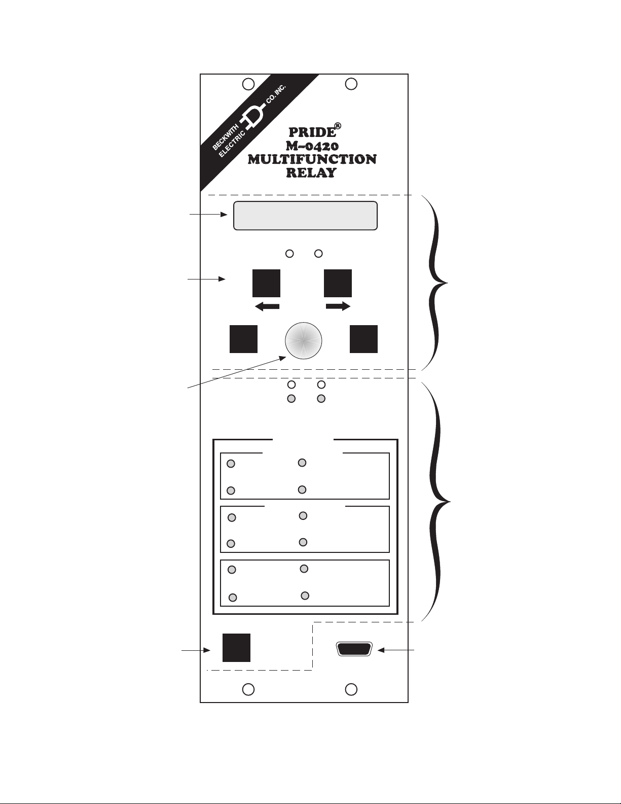
M-0420 Instruction Book
Liquid Crystal
Display
Left/Right Buttons
Rotary Knob
VOLTAGE RELAY
VOLT freq curr powr
FUNCTION
EXIT
RECORDED
SELECT
POWER
FAULT
ENTER
SETPOINT
TARGETS
PHASE ELEMENTS
59
OVERVOLTAGE
27
UNDERVOLTAGE
NEUTRAL ELEMENTS
59 N
OVER VOLTAGE
27 N
UNDERVOLTAGE
81 O
OVERFREQUENCY
81 U
UNDERFREQUENCY
51/67
OVERCURRENT
50
INSTANTANEOUS
OVERCURRENT
51 N
OVERCURRENT
50 N
INSTANTANEOUS
OVERCURRENT
NEGATIVE SEQUENCE
OVERCURRENT
DIRECTIONAL
OVERPOWER
ENTER
RELAY OK
BREAKER
CLOSED
46
32
➞
User Interface
Indicators
and Controls
Target/Status
Indicators
and Controls
3–2
Target Reset/
Lamp Test
Button
SERIAL INTERFACE
TARGET RESET/
LAMP TEST
Made in U.S.A.
COM 1
Figure 3-1 M-0420 Front Panel
Serial Port
Page 55

Front Panel Controls – 3
EXIT Button
Use the
EXIT
button to exit from a displayed
screen and return to the immediately preceding
menu.
ENTER Button
The
ENTER
button is used to choose a highlighted
menu selection, to replace a setpoint or other
programmable value with the currently displayed
value, or to select one of several displayed options,
such as ENABLE or DISABLE a function.
ROTARY Knob
Use the rotary knob to increment (by rotating
clockwise) or decrement (by rotating counterclockwise) a value currently displayed. (This new value is not stored and does not affect the unit’s
calculations until
ENTER
is pressed.) For values
with a large range, use the left/right arrow buttons to move the cursor (an underline) to any
digit. Incrementing and decrementing will then
start with the underlined digit.
You can also use the rotary knob instead of the
left/right arrow buttons to choose among menu
selections displayed on the LCD.
Fault Recorded LED
The red FAULT RECORDED LED will light to
indicate that fault data has been recorded in the
unit’s memory in response to a 52b breaker open
status, if the fault recorder has been armed. You
can arm or disarm the fault recorder using the
FAULT RECORDER menu selection.
Breaker Closed LED
The red BREAKER CLOSED LED will light to
indicate when the breaker status input (52b) is
open.
TARGET Indicators and Target Reset/Lamp
Test Button
Normally, the twelve red target LEDs are not lit.
If the unit trips, the LEDs corresponding to the
cause(s) of the trip will light and stay lit until
reset. Pressing and releasing the TARGET RESET/
LAMP TEST button will momentarily light all LEDs
(providing a means to test them) and reset the
target LEDs if the trip condition is not present.
Detailed information about the cause of the last
five trips is, however, retained in the unit’s memory
for access through the display via the VIEW
TARGET HISTORY menu.
3.2 Target/Status Indicators and Controls
The target/status indicators and controls consist
of the POWER and RELAY OK LEDs, the FAULT
RECORDED and BREAKER CLOSED LEDs, the
twelve target LEDs, and the
TEST
button.
TARGET RESET/LAMP
POWER LED
The green POWER LED indicator will remain lit
whenever power is applied to the unit.
Relay OK LED
The green RELAY OK LED is under control of
the relay's microprocessor. For units having
software version 4.00 and above, you can program
this LED either to flash or to remain on continuously
when the relay is functioning properly. To make
this selection, go to the SETUP UNIT menu, use
the right-arrow button or rotary knob to display
the RELAY OK LED FLASH menu, and select
either DISABLE or ENABLE.
Pressing and holding the
TARGET RESET/LAMP TEST
button will display the pick up status of the relay
functions.
3.3 Serial Interfaces (COM 1 and COM 2)
The SERIAL INTERFACE COM 1 port is a standard
9-pin RS-232C communications port. This port
will normally be used for local setting and
interrogation of the relay via a portable computer.
An additional port, COM 2, is available at the
rear of the relay. This 25-pin port will normally be
used for remote setting and interrogation of the
relay via a modem and a compatible
communications protocol. Detailed information on
the use of the communications ports is provided
in Appendix C, Communications and the M-0429A
BECOCOM®/M-0428A BECOPLOT® User’s Guide.
3–3
Page 56

M-0420 Instruction Book
This Page Intentionally Left Blank
3–4
Page 57

4 Operation
4.1 Introduction ................................................................................. 4–1
4.2 Software Flow ............................................................................. 4–1
4.3 Moving Between Menus............................................................. 4–5
4.4 Entering Values ..........................................................................4–5
4.5 Access Codes ............................................................................ 4–8
Operation – 4
4.6 Enabling and Disabling Relay Functions .................................. 4–8
4.1 Introduction
While the M-0420 Multifunction Relay is a
sophisticated unit that performs a number of
complex functions, care has been taken to make
it easy to use. This chapter provides general
information on the software flow and the use of
the front panel controls to maneuver through the
menus, enter values, and set and interrogate the
unit. Figure 4-1 illustrates the overall software
flow. Detailed information on each menu selection
is provided in Chapter 5, MENU REFERENCE.
4.2 Software Flow
Power-On Self-Test and Status Screens
Each time it is powered up, the relay performs a
number of self-tests to ensure its correct operation.
During the self-tests, the display presents a
lowercase “x” for each test successfully executed.
When all tests have been executed successfully,
it will briefly display PASS and then a series of
unit status screens, including the Beckwith Electric
Co. copyright notice, the software version number,
the serial number of the unit, the date and time
as set in the system clock, and the default user
logo (Beckwith Electric Co.). (Figure 4-2 illustrates
this sequence of screens.) If any test should
fail, an error code will be displayed and the unit
will not allow operation to proceed. In such a
case, note the error code and contact the factory.
A list of error codes and their descriptions is
provided in Appendix B, Self-Test Error Codes.
Default Message Screens
Normally, when the relay is powered and unattended,
the display is blanked to increase its life-span.
The display is automatically blanked after exiting
from the main menu and from
after 5 minutes of unattended operation.
However, if the unit has tripped and has not been
reset, it will display the time and date of the trip
and will automatically cycle through status screens
for each applicable target. (This sequence is
illustrated in Figure 4-3.) In either case, pressing
ENTER
will begin local mode operation, displaying
the access code entry screen or, if no access
code has been defined, the first-level menu.
most
other screens
4–1
Page 58
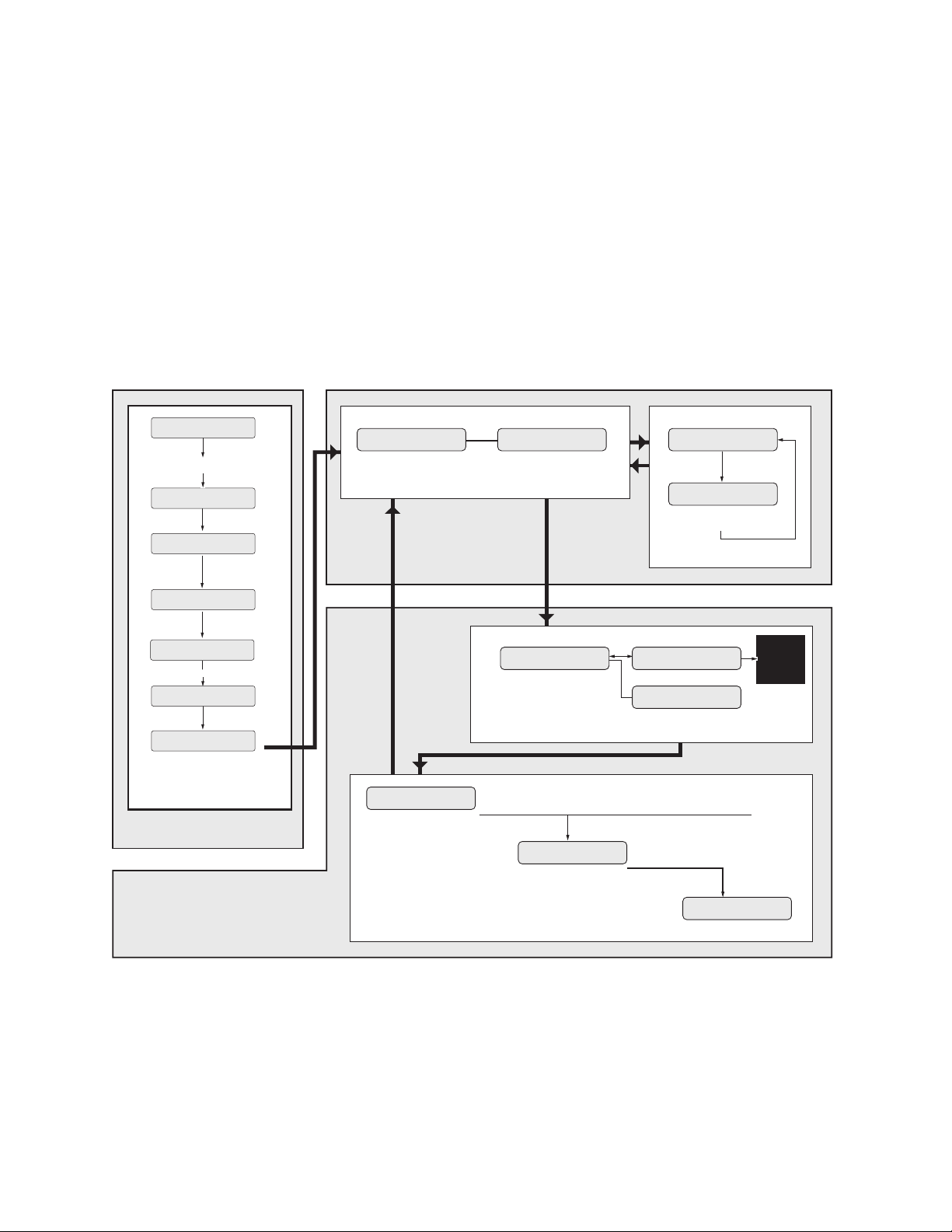
M-0420 Instruction Book
Self-Tests
POWER ON SELFTESTS
XXXXXXXX
LED Test
POWER ON SELFTESTS
PASS
Model Number
Beckwith Electric Co.
M-0420
Software Version
Beckwith Electric
D - 0020V04.01 - 32
Serial Number
Beckwith Electric Co.
SERIAL NUMBER 114
System Date and Time
Beckwith Electric Co.
06/15/93 15:24:32
Default Logo
Beckwith Electric Co.
M-0420
BECKWITH ELECTRIC CO.
Blanked Screen
M-0420
Default Message Screens
ENTER ACCESS CODE
Access Screens (optional)
-TRGT- 06/22/93 10:19:12
Trip #47
-TRGT- 06/22/93 10:19:12
NEUTRALTIME OVERCURRENT
Trip Target Screens
0
ACCESS DENIED!
LEVEL 1 ACCESS GRANTED!
5-minute
access
lockout
Power-On Self-Test and
Status Screens
VOLTAGE RELAY
➞
recon setpts stat config targets fault_rec count comm setup exitVOLT freq curr powr
Power-On
OVERVOLTAGE SETPOINTS
PHASE_OVER phase_under nutrl_over nutrl_under
Local Mode
Main Menu Flow
■ NOTE: Communications through the front/rear-panel communications ports is suspended while the
M-0420 is in local mode.
Figure 4-1 Software Flow
4–2
➞
PHASE OVERVOLTAGE #1
132 VOLTS (1.10 P U)
Page 59
Self-Tests
POWER ON SELFTESTS
XXXXXXXX
LED Test
POWER ON SELFTESTS
PASS
Model Number
Beckwith Electric Co.
M-0420
Operation – 4
Software Version
Beckwith Electric
D - 0020V04.01 - 32
Serial Number
Beckwith Electric Co.
SERIAL NUMBER 114
System Date and Time
Beckwith Electric Co.
06/15/93 15:24:32
Default Logo
Beckwith Electric Co.
M-0420
Figure 4-2 Power-On Self-Test and Status Screens
4–3
Page 60
M-0420 Instruction Book
-TRGT- 06/22/93 10:19:12
Trip Target Screens
cycles through
continuously
Trip #47
these screens
•••
status
screens
additional
NEUTRAL TIME OVERCURRENT
-TRGT- 06/22/93 10:19:12
if necessary
Trip Target Screens
from Power-On Self-Test screens
operation
after a trip
Default Message Screen*
BECKWITH ELECTRIC CO.
seconds
after several
screen briefly
default message
ENTER
M-0420
ENTER
first-level menu
button from
EXIT or EXIT
after 5
minutes
screens
from most
ENTER
displayed
if screen blanking is enabled.
will blank after a short period of time
else Beckwith Model Number. Screen
Displays user logo screen if defined,
*
4–4
Blanked Screen*
Default Message Screens
Figure 4-3 Default Message Screens
Page 61

Operation – 4
■ NOTE: Communication through the front- and
rear-panel communication ports is suspended while
the unit is in local mode. To resume communication and ensure security, you should always exit
from the main menu after configuring or interrogating the relay from the front panel.
Access Screens
To prevent unauthorized access to relay functions,
the software has the provision for assigning access
codes. If access codes have been assigned, the
access code entry screen, illustrated in Figure
4-4, Access Screens, will be displayed after
ENTER
is pressed from the default message screen (see
above). The relay is shipped with the access
code feature disabled.
If a valid access code is entered, the unit will
notify the user that access has been granted.
However, on the third entry of an invalid code
the unit will lock out access through the front
panel for five minutes. Detailed information on
defining and entering access codes is provided
below and in Chapter 5, Menu Reference.
Menu Flow
If access is granted, the unit will display the
first-level menu. This left-to-right scrolling menu
provides access to a second level of menus which
in turn provide access to the protective functions.
Figure 4-5, Front Panel Operation, illustrates the
relationship between the menu levels and the
use of the front panel controls to navigate between
them. Detailed information on the use of the front
panel controls for moving between menus is
provided below.
4.3 Moving Between Menus
Once the desired menu selection has been highlighted, it is chosen by pressing the ENTER button. Depending on the menu selection chosen,
the display shows either a second-level menu
(with the SELECT FUNCTION LED lit), a value
to be inspected or changed, or a choice to be
made, such as enable or disable. (If a value can
be changed or a selection can be made, the
ENTER SETPOINT LED will be lit.)
4.4 Entering Values
Numeric values must be entered for the setpoints,
for certain configuration data, and for access
codes. When a value must be entered, the unit
will light the ENTER SETPOINT LED as a prompt.
A value is entered or changed by incrementing or
decrementing the currently displayed value using
the rotary knob. Turning the knob clockwise will
increment the displayed value. Turning the knob
counterclockwise will decrement the displayed
value.
■ NOTE: While the rotary knob has click detents,
these are only to provide tactile feedback. Passing
one detent does not necessarily mean that the
displayed value will be incremented or decremented
by one. Turning the knob too quickly may result
in an unanticipated change in the displayed value.
As shown in Figure 4-5, an underline cursor is
displayed in the position of the least significant
digit of the value to be entered or changed. When
the value to be incremented has a wide range,
the left/right arrow buttons can be used to move
the underline to any displayed digit. Turning the
front panel knob will increment or decrement the
value beginning with the underlined digit.
As shown in Figure 4-5, each menu has two
lines. On the bottom line appear lower case abbreviations of each menu selection with the current menu selection “highlighted” by being displayed
in upper case. An expanded description of the
highlighted menu selection is displayed on the
top line of the display. The left and right arrow
buttons are used to highlight the desired menu
selection. If more selections exist on a given
menu than can be displayed at one time, an
arrow at one or both sides of the display signifies that the display will scroll in that direction.
As a prompt, the SELECT FUNCTION LED lights
to signify that a menu selection should be made.
Once the value is set, press the
ENTER
button to
store the new value into the unit’s memory. It
will become the active setpoint as soon as
ENTER
is pressed (unless inhibited by the presence of
another function).
■ NOTE: The relay will not allow you to enter a
digit outside the applicable range of values. See
the table of values for each function in Chapter
2, Application, for a detailed listing of the setpoint
ranges and initial settings.
4–5
Page 62
M-0420 Instruction Book
access
lockout
5-minute
attempt
on third failed
ACCESS DENIED!
to First-Level Menu
LEVEL 1 ACCESS GRANTED!
to select digit
ENTER
SETPOINT
0
SELECT
ENTER ACCESS CODE
from Default Message screens
Access Screen
FUNCTION
four digits
can be up to
access code
underlined
selected digit
to select digit
password value
displayed
to enter
ENTER
to increment
EXIT
or decrement
displayed value
4–6
access code to 9999.
setting), set the Level 3
function (the default
optional. To disable this
Access codes are
*
Figure 4-4 Access Screens
Access Screens (optional*)
Page 63
into memory
setpoint value
displayed
to enter
Operation – 4
ENTER
SETPOINT
to select digitto select digit
ENTEREXIT
Setpoint Display
132 VOLTS (1.10 PU)
SELECT
PHASE OVERVOLTAGE #1
digit
selected
underlined
nutrl_over nutrl_under
Second-Level Menu
➞
highlighting
to move
ENTER
SETPOINT
SELECT
OVERVOLTAGE SETPOINTS
FUNCTION
PHASE_OVER phase_under
to move
lower-level
to select
FUNCTION
menu
to move
highlighting
EXIT ENTER
menu
return to
previous
to increment
level
selected digit
or decrement
displayed value
beginning with the
highlighting
level
menu
return to
previous
First-Level Menu
recon setpts stat config targets fault_rec count comm setup exit
from Access screens
➞
highlighting
to move
ENTER
SETPOINT
SELECT
VOLTAGE
FUNCTION
VOLT freq curr powr
to move
highlighting
(all caps)
selection
highlighted
selection
highlighted
description of
Figure 4-5 Front Panel Operation
menu
lower-level
to select
EXIT ENTER
Default
return to
Message
to move
highlighting
Screen
Main Menus
4–7
Page 64

M-0420 Instruction Book
4.5 Access Codes
The M-0420 Multifunction Relay supports three
levels of access codes. Depending on the access code they hold, users have varying levels
of access:
Level 3 access – access to all relay func-
tions and diagnostics
Level 2 access – read and change setpoints,
monitor status, view trip history
Level 1 access – read setpoints, monitor
status, view trip history
■ NOTE: Each access code is a user-defined
one- to four-digit number. If the Level 3 access
code is set to 9999, the access code feature is
disabled. When this feature is disabled, the access screens are bypassed.
Access codes are entered in the same manner
as any other value, using the rotary knob (and
the left and right arrow buttons, if desired). Access
codes can be altered by choosing the ALTER
ACCESS CODES menu selection under the SETUP
UNIT menu.
4.6 Enabling and Disabling Relay Functions
Each relay function can be individually enabled
or disabled via the CONFIGURE RELAY menu
selection. To enable or disable a function, merely
highlight the ENABLE or DISABLE choice for
the appropriate function under the CONFIGURE
RELAY menu and press
will not appear
However, if
under any other menu or screen.
all
functions of a device (individual
ENTER
. A disabled function
target) are disabled, the message FUNCTION(S)
DISABLED—SEE CONFIGURE MENU will appear
if it is selected.
■ NOTE: Functions having two setpoints are
shipped with the second setpoint disabled. Disabling
unused functions improves the response time of
the indicators and controls.
▲ CAUTION: If you forget your access code,
you will have to contact the factory for information on resetting the unit.
4–8
Page 65

Menu Reference – 5
5 Menu Reference
5.1 Introduction ................................................................................. 5–1
5.2 Relay Functions .........................................................................5–1
5.3 Review Setpoints ....................................................................... 5–2
5.4 Monitor Status ............................................................................ 5–2
5.5 Configure Relays ........................................................................5–3
5.6 View Target History ................................................................... 5–4
5.7 Fault Recorder ............................................................................5–4
5.8 Read Counter.............................................................................. 5–5
5.9 Communication ...........................................................................5–5
5.10 Setup Unit ...................................................................................5–6
5.11 Exit Local Mode ......................................................................... 5–7
5.12 Menus ......................................................................................... 5–8
5.1 Introduction
This chapter provides a short description for each
main menu selection available in the M-0420
Multifunction Relay Version 4.01 software. Flowcharts are provided for the relay configuration
menus. (Figure 5-1, M-0420 Menu Flow, summarizes the main menu flow.) The functions in this
chapter are presented in the same order as on
the main menu.
■ NOTES: The descriptions assume that the
relay settings are enabled or disabled as shipped
from the factory (see Figure 7-1).
5.2 Relay Functions
Voltage Relay
VOLTAGE RELAY
VOLT freq curr powr C
The VOLTAGE RELAY menu selection provides
access to the voltage functions of the relay. Figures 5-2 through 5-6 illustrate the software flow
for these functions. Setpoint ranges and initial
settings are provided in Chapter 2, Application,
and in the Specifications at the front of this book.
Setpoint Configuration Record Forms are provided
in Appendix E, Configuration Record Forms.
These forms provide a comprehensive,
standardized means of recording setpoint values.
5–1
Page 66

M-0420 Instruction Book
Frequency Relay
FREQUENCY RELAY
volt FREQ curr powr C
The FREQUENCY RELAY menu selection provides
access to the frequency functions. Figures 5-7
and 5-8 illustrate the software flow for these
functions. Setpoint ranges and initial settings are
provided in Chapter 2, Application, and in the
Specifications at the front of this book.
Current Relay
CURRENT RELAY
volt freq CURR powr C
The CURRENT RELAY menu selection provides
access to the current functions. Figures 5-9 through
5-12 illustrate the software flow for these functions.
Setpoint ranges and initial settings are provided
in Chapter 2, Application, and in the Specifications
at the front of this book.
■ NOTE: During the time that a setpoint associated
with the inverse time/instantaneous phase
overcurrent, phase directional overcurrent, inverse
time/instantaneous neutral overcurrent, or negative
sequence overcurrent functions is being changed,
that function and the functions associated with it
are disabled. They are re-enabled when you exit
from the setpoint menu.
Reconnect Relay
RECONNECT RELAY
B RECON C
The RECONNECT RELAY menu selection pro-
vides access to the reconnect function. Figure
5-15 illustrates the software flow for this function. Setpoint ranges and initial settings are provided in Chapter 2, Application, and in the
Specifications at the front of this book.
5.3 Review setpoints
REVIEW SETPOINT
B SETPTS stat config C
The REVIEW SETPOINT menu selection enables
you to review the existing settings of all
enabled
setpoint values and time delays. This menu can
only be scrolled forward and cannot be scrolled
backward.
■ NOTE: Setpoint values cannot be changed via
this menu.
5.4 Monitor status
MONITOR STATUS
B setpts STAT config C
■ NOTE: Function 67, phase directional
overcurrent, is an option that may be purchased
for installation at the factory. If 67 is present,
and the directional function is enabled, additional
setpoint screens appear in the CURRENT RELAY
menu, as shown in Figures 5-9 and 5-10.
Power Relay
POWER RELAY
volt freq curr POWR C
The POWER RELAY menu selection provides
access to the power functions. Figures 5-13 and
5-14 illustrate the software flow for these functions. Setpoint ranges and initial settings are provided in Chapter 2, Application, and in the
Specifications at the front of this book.
5–2
The MONITOR STATUS menu selection enables
you to examine the system status and the relay
timers in real-time for each function. Each status
display may be scrolled in either direction by
means of the front panel knob. The second-level
menu presents the following status options:
Voltage Status: including phase, neutral, peak
phase, positive, negative, and zero sequence
voltages.
Frequency Status
■ NOTE: If there is no VT input, the FREQUENCY
STATUS menu reports LOW VOLT DISABLE. If
the applied positive sequence voltage is approximately below 20 V, the FREQUENCY STATUS
menu displays LOW VOLT DISABLE.
Current Status: including phase, neutral, and
negative sequence currents.
Page 67

Menu Reference – 5
Power Status: including real and reactive power,
and power factor.
Voltage Timer
Frequency Timer
Current Timer
Power Timer
Reconnect Timer
Fuse Status: including the external VT fuses
and the relay's internal fuses.
Temperature: the unit’s internal temperature as
reported by the on-board temperature sensor
Time of Last Power Up
5.5 Configure Relays
CONFIGURE RELAYS
B setpts stat CONFIG C
The CONFIGURE RELAYS menu selection allows you to enable or disable the individual relay
functions and to optimize the relay for either generator or intertie protection.
Functions are grouped under the following submenus: Voltage Relay, Frequency Relay, Current Relay, Power Relay, Trip Circuit Type (Intertie
or Generator), and VT Fuse Loss.
Voltage/Frequency/Current/Power Relays
Each of these menus allows you to enable or
disable individual relay functions. To enable or
disable a function, highlight the ENABLE or
DISABLE choice for the appropriate function and
press
ENTER
. (Some functions have additional
choices to allow you to enable or disable specific
features.) The CONFIGURE menu for the phase
overcurrent relay is shown in Figures 5-17 and
5-18.
the 51V function can be directionally controlled
by enabling the directional control selection for
the 51V function under the configuration menu.
(Note that disabling unused functions improves
the response of the user indicators and controls.)
Trip Circuit Type
TRIP CIRCUIT TYPE
INTERTIE generator
The M-0420 Multifunction Relay can be optimized
for either generator or intertie protection by means
of the TRIP CIRCUIT TYPE screen. To select
the trip circuit type, highlight the desired selection
and press
ENTER
.
When INTERTIE is selected, all functions work
as described in this Instruction Book.
When GENERATOR is selected, the relay inhibits
the trip outputs from the 27, 81O, 81U, 27N,
32F, and 32R functions when the 52b status input
(closed contact) indicates that the breaker is open.
This feature ensures that the relay will not send
an unwanted trip signal while the generator is offline, such as when being brought up to speed.
The functions, however, are still active, and their
setpoints can be changed.
When GENERATOR is selected, the following
conditions must be true:
• The 52b breaker status input
must
be con-
nected.
• The high-speed option on the reverse power
and directional overcurrent functions
not
be selected.
must
Additionally, more accurate response will be
achieved during off-nominal-frequency operation
if the total waveform (including harmonics) is used
as the basis for the rms magnitude of voltage
and current. (This option is selected by setting
switch 8 of the internal configuration DIP switch
to ON.)
■ NOTE: A disabled function
will not appear
under
any menu or screen other than the CONFIGURE
RELAYS menu. If all functions for a relay are
disabled, the message FUNCTION DISABLED
\SEE CONFIG MENU will be displayed when the
main menu selection is chosen. Additionally, certain
functions can have their operation modified by
other functions or menu selections; for example,
■ NOTE: Functions 59N and 27N respond to the
fundamental frequency component regardless of
the setting of DIP Switch 8.
5–3
Page 68

M-0420 Instruction Book
VT Fuse Loss Detection
INTERNAL FUSE LOSS LOGIC
disable ENABLE
Internal VT fuse-loss detection can be enabled
or disabled under user control. Additionally, blocking
of the 27, 51V, 67, and 32R functions during a
fuse-loss condition can be individually selected.
As shown in Figure 5-19, fuse-loss detection and
blocking are selected via the CONFIGURE V.T.
FUSE LOSS menu under the CONFIGURE
RELAYS menu selection.
5.6 View target History
VIEW TARGET HISTORY
B TARGETS fault_rec C
The VIEW TARGET HISTORY menu enables you
to review the targets for the previous five trip
conditions. As shown in Figure 5-18, Example of
Target History Screens, the target history for each
trip cycles continuously through a sequence of
screens until you press
EXIT
. Both status
information (which indicates when a value was
outside the setpoint range) and timer information
(which indicates when a value was outside the
setpoint range and the timer expired) are shown,
along with individual phase element information
where appropriate. A time/date tag and the trip
counter are also displayed. The second-level menu
presents Target Information #0–4, with Target 0
being the latest trip. You can clear all trip history
data to provide a clean starting point for further
target recording by pressing
ENTER
at CLEAR
TARGET HISTORY screen.
5.7 Fault Recorder
FAULT RECORDER
B targets FAULT_REC C
The fault recorder function records comprehensive fault data from the three phase and the
neutral voltages and the three phase and the
neutral currents at 16 samples per cycle (960
Hz), and from the 52b and 60 FL status inputs at
480 Hz. The FAULT RECORDER menu selection
enables you to determine the status of the fault
recorder (whether armed or not, and if armed,
whether triggered or not), and to arm or disarm
the recorder. Fault recorder information can be
downloaded via the RS-232C ports to an IBMcompatible personal computer running the M-0429A
BECOCOM® Communications Software package.
Once downloaded, you can examine the waveform data and output it using the M-0428A BECOPLOT® Fault Data Analysis Software package.
(Refer to the M-0429A BECOCOM®/M-0428A
BECOPLOT® User’s Guide for more information
on downloading and analyzing fault data.)
The fault recorder can be either armed or disarmed. In the armed condition, the fault recorder
will be triggered to freeze the data when a breaker open (52b) signal is present. The status display changes from ARMED to TRIGGERED.
When armed but not triggered, the recorder continuously records waveform data, keeping the data
from the most recent 96 cycles in its memory.
When the breaker opens, as indicated by the
external contact closure at the 52b status input,
the recorder is triggered. It continues recording
for a minimum of four to six additional cycles
(default value is 5% post-trigger data acquisition)
and then goes to disarmed mode, keeping the
95% pre-fault and 5% post-fault snapshot of waveform data in its memory for downloading via the
BECOCOM software. This software also permits
the user to trigger the fault recorder manually.
5–4
■ NOTE: The fault recorder is initially disarmed
after power up. To arm the fault recorder, choose
the ARM menu selection and press
ENTER
; the
recorder will be armed.
Page 69

Menu Reference – 5
Automatic Fault Recorder Re-arming
The fault recorder can be set to rearm itself automatically under the FAULT RECORDER menu
selection. When auto-rearming is enabled, the
fault recorder is armed when the breaker closes
(as indicated by the 52b contact opening input)
and triggered when the breaker opens.
▲ CAUTION: The previous fault record is lost
once the recorder is rearmed. When auto-rearming is enabled, the fault record must be downloaded while the breaker is open.
POST TRIGGER DELAY
The post trigger delay function permits you to
vary the distribution of data before and after the
fault over the range from 5% to 95% of the 96
cycles.
5.8 Read Counter
READ COUNTER
B COUNT comm setup exit
The system counters count the number of trip,
close, self-test alarm indications, and power-loss
situations. By pressing
ENTER
from the READ
COUNTER menu, you can determine the present
count of each counter, and, if desired, clear them.
The second-level menu presents the counters in
the following order: Trip Counter, Close Counter,
Alarm Counter, Power Loss Counter, Clear Trip
Counter, Clear Close Counter, Clear Alarm Counter,
Clear Power Loss Counter
Configure COM 1/Configure COM 2
CONFIGURE COM1
COM1 com2 com_adr accssC
The CONFIGURE COM1 and CONFIGURE COM2
menu selections enable you to set the baud rate
and parity for the front- and rear-panel RS-232C
ports. The relay can communicate at up to 9600
baud and with even parity or no parity (parity
disabled).
■ NOTE: These parameters must match those
of the attached modem, computer, or other communications device. The default parameters have
been chosen to match the default parameters
supplied with the M-0429A BECOCOM Communications Software package.
Communication Address
COMMUNICATION ADDRESS
com1 com2 COM_ADR accssC
The communication address capability allows
multiple units (M-0420 Multifunction Relay or other
compatible Beckwith products) to share a phone
line or modem. Each relay can be given an individual
address ranging from 1–200. All relays have the
group address of 230. More information on the
use of communication addresses is provided in
the Chapter 2, Application, of the M-0429A
BECOCOM/M-0428A BECOPLOT Software User’s
Guide.
Comm Access Code
5.9 Communication
COMMUNICATION
B count COMM setup exit
You can configure the relay for communication
via the RS-232C ports using the COMMUNICATION
menu. In a typical communications application,
the rear-panel communication port is permanently
connected to a modem, while the front-panel port
is kept free for on-site programming via a laptop
PC. The second-level menu selections are
described below. Refer to the M-0429A
BECOCOM®/M-0428A BECOPLOT® Software
User’s Guide, and to Appendix C, Com-
munications, of this Instruction Book for detailed
information about these functions.
COMMUNICATION ADDRESS
com1 com2 com_adr ACCSSC
This function enables you to restrict communications access to the function setpoints by establishing a security access code. Setting the access
code to 0 will disable this protection.
Issue COM2 Modem Log On
ISSUE COM2 MODEM LOG ON
B ISSUE enter
The ISSUE COM2 MODEM LOG ON menu selection enables you to send the predefined COM2
initialization parameters to the attached communication device. These parameters may be used
for initializing a modem, and are defined using
the ENTER COM2 MODEM LOG ON command.
5–5
Page 70

M-0420 Instruction Book
Enter COM2 Modem Log On
ENTER COM2 MODEM LOG ON
B issue ENTER
Using the ENTER COM2 MODEM LOG ON menu,
you can define a string of initialization parameters
to be sent using the ISSUE COM2 MODEM LOG
ON menu selection. These parameters are also
sent on power-up. For a Hayes-compatible modem
set as receiver, the following string might be
used:
AT EØ QV &DØ SØ=2 X4 M1
If the first character of the ENTER COM2 MODEM
LOG ON string is a space character, no log-on
string will be issued through the COM2 port, in
effect disabling the Log On function.
Many factors are involved in choosing the current
characters for the log-on string including
manufacture, type, speed and default settings of
the modem selected. Some modems allow all
parameters to be set up before installation, thereby
eliminating the need for the modem string
altogether.
Beckwith Electric has a series of application notes
relating to communications issues. Please contact
the factory at (727) 544-2326 for further information.
5.10 Setup Unit
SETUP UNIT
B count comm SETUP exit
The SETUP UNIT menu selection enables you to
perform tasks necessary to set up the unit for
operation. The second-level menu selections are
described below.
Software Version
Alter Access Codes
ALTER ACCESS CODES
vers ACCESS time dispC
The ALTER ACCESS CODES menu selection
enables you to define and change access codes.
The relay supports three levels of access codes:
Level 3 access – access to all relay functions
(including defining or changing access codes)
Level 2 access – read and change setpoints,
monitor status, view trip history
Level 1 access – read setpoints, monitor
status, view trip history
Each access code is a one to four digit number.
If the level 3 access code is set to 9999, the
access code feature is disabled. Access codes
are entered in the same manner as any other
value, using the rotary knob and the left/right
arrow buttons.
■ NOTE: If access codes are enabled (the level
3 code is set to something other than 9999), you
must have level 3 access to alter any access
code. If you forget your access code, you will
have to contact the factory for information on
resetting the unit.
Date & Time
DATE & TIME
vers access TIME dispC
The DATE & TIME menu selection enables you
to set the unit’s internal clock to the current date
and time, to synchronize the clock, to start and
stop the clock, and to calibrate the clock’s time
base.
■ NOTE: The unit is shipped with the clock
stopped.
SOFTWARE VERSION
VERS access time dispC
The SOFTWARE VERSION menu selection pre-
sents the current software version. This menu
selection displays the same software version
number that is displayed when system power is
turned on.
5–6
LCD Display Blanking
LCD DISPLAY BLANKING
Bvers access time DISPC
The LCD DISPLAY BLANKING menu selection
enables you to select the screen-blanking option
for the Liquid Crystal Display. When screen-blanking
is enabled, the LCD will blank two seconds after
EXIT
is chosen from the top-level menu and after
five minutes of unattended operation from
most
other menus. This feature is enabled as shipped
from the factory.
Page 71
Menu Reference – 5
Input User Logo
USER LOGO LINE 1
BLOGO1 logo2 dipsw C
The INPUT USER LOGO menu selection enables
you to enter two alphanumeric lines (User Logo 1
and User Logo 2) to identify the unit. If these
lines are defined, they will be displayed instead
of the Beckwith Electric Co. screen at certain
times. The information on these screens is also
automatically transmitted via COM1 and COM2
during remote communications in order to aid in
identifying the relay. To enter a line, first use the
left- and right-arrow keys to move the cursor to
the location of the desired character. Next, use
the front panel knob to select the desired character from the ASCII character set. Repeat this
procedure for each character in the message.
When the desired message has been entered,
press
ENTER
.
■ NOTE: The user logo screens will be dis-
played if the first character of line 1 (the top
menu line) is any character
other than a space
If a space character is present, this feature is
disabled.
DIP Switch settings
DIP SWITCH SETTINGS
Blogo1 logo2 DIPSWC
1X 8 OFF DIPSWITCH
XXXXXXX on
C.T. PHASE RATIO
1.0:1
C.T. NEUTRAL RATIO
1.0:1
In order for the M-0429A BECOCOM
Communications Software program to properly
display primary values for voltages, currents, and
power, the program must have available the
appropriate VT and CT ratios. For this reason,
the relay can be programmed with VT and CT
ratios. During communications, these ratios are
transmitted to the BECOCOM program. These
ratios are always set as X to 1. For example, if
the VT is a 600 V/120 V or 575 V/115 V, the
ratio would be input as 5.0 to 1.
■ NOTE: These ratios are used for BECOCOM
display purposes only; they are not used in the
relay for any calculations and need not be set if
remote communication is not desired.
.
■ NOTE: When the VT secondary voltage has
been chosen to be 120 V (via the internal configuration DIP switch), the VT ratios should be calculated as marked on the VT. However, when
69.3 V has been selected, the VT ratio should be
divided by S3. For example, a 600 V/69.3 V VT
has a ratio of 600/(69.3 x S3) = 5 or 5.0:1.
(When the 69.3 V option is selected, the M-0420
internally scales the input voltages by a factor of
S3 to provide a nominal 120 V. Hence the S3
factor in the above equation.)
®
The DIP SWITCH SETTINGS menu enables you
to determine the setting of the internal configuration DIP switches. Choosing this menu selection
will display the default screen shown below (60
Hz version). For further information about the
DIP switches, see Chapter 6, Installation.
VT and CT Ratios
VT & CT RATIOS
B RATIO
V.T. PHASE RATIO
1.0:1
V.T. NEUTRAL RATIO
1.0:1
When the VT inputs are selected as line-to-ground
through DIP switch 5, primary line voltages are
displayed as follows:
VAB = VAS3VBC = VBS3VCA = VCS3
Because of the many connections and ratios
available with CTs and VTs, experimentation with
various ratios may be required to achieve the
proper primary value display.
5.11 EXIT LOCAL MODE
EXIT LOCAL MODE
B count comm setup EXIT
Pressing
ENTER
when EXIT LOCAL MODE is dis-
played returns you to the default message screens.
5–7
Page 72
M-0420 Instruction Book
5.12 Menus
VOLTAGE RELAY
VOLT freq curr powr
• RMS Phase Overvoltage Setpoints
• Peak Phase Overvoltage Setpoints
• RMS Phase Undervoltage Setpoints
• RMS Neutral Overvoltage Setpoints
• RMS Neutral Undervoltage Setpoints
RECONNECT RELAY
RECON
• Reconnect Setpoints
• Delay Reconnect
VIEW TARGET HISTORY
TARGETS fault_rec
• Trip 0
• Trip 1
• Trip 2
• Trip 3
• Trip 4
• Clear Target History
FREQUENCY RELAY
volt FREQ curr powr
• Over Frequency Setpoints
• Under Frequency Setpoints
REVIEW SETPOINTS
SETPTS stat config
FAULT RECORDER
targets FAULT_REC
• Status Armed/Triggered
• Arm Recorder
• Disarm Recorder
• Auto Re-Arm Recorder
CURRENT RELAY
volt freq CURR powr
• Phase Overcurrent Setpoints
• Phase Directional Overcurrent Setpoints
• Phase Inst Overcurrent Setpoints
• Neutral Overcurrent Setpoints
• Neutral Inst Overcurrent Setpoints
• Negative Sequence Overcurrent Setpoints
MONITOR STATUS
setpts STAT config
•
•
•
• Voltage Status
• Frequency Status
• Current Status
• Power Status
• Voltage Timer
• Frequency Timer
• Current Timer
• Power Timer
• Reconnect Timer
• Temperature
• Fuse Status
READ COUNTER
COUNT comm setup exit
• Trip Counter
• Close Counter
• Alarm Counter
• Power Loss Counter
• Clear Trip Counter
• Clear Close Counter
• Clear Alarm Counter
• Clear Power Loss Counter
POWER RELAY
volt freq curr POWR
• Forward Power Setpoints
• Reverse Power Setpoints
CONFIGURE RELAYS
setpts stat CONFIG
• Voltage Relay
• Frequency Relay
• Current Relay
• Power Relay
• Trip Circuit Type
• VT Fuse Loss
COMMUNICATION
count COMM setup exit
• Configure COM1
• Configure COM2
• Communication Address
• Issue COM2 Modem Log On
• Enter COM2 Modem Log On
5–8
SETUP UNIT
count comm SETUP exit
• Software Version
• Alter Access Codes
• Date & Time
• LCD Display Blanking
• User Logo Line 1
• User Logo Line 2
• DIP Switch Settings
• VT & CT Ratios
EXIT LOCAL MODE
count comm setup EXIT
Figure 5-1 M-0420 Menu Flow, Version 4.01 Software
Page 73
Menu Reference – 5
SELECT
FUNCTION
SELECT
FUNCTION
SELECT
FUNCTION
SELECT
FUNCTION
ENTER
SETPOINT
ENTER
SETPOINT
ENTER
SETPOINT
ENTER
SETPOINT
VOLTAGE RELAY
VOLT freq curr powr
ENTER
OVERVOLTAGE SETPOINTS
PHASE_OVER phase_under
ENTER
PHASE OVERVOLTAGE #1
132 Volts (1.10PU)
Rotate knob to setpoint value
ENTER
DELAY PHASE OVERVOLT #1
30 Cycles
➞
➞
EXIT
EXIT
EXIT
Rotate knob to setpoint value
ENTER
SELECT
FUNCTION
SELECT
FUNCTION
ENTER
SETPOINT
ENTER
SETPOINT
PHASE OVERVOLTAGE #2
132 Volts (1.10PU)
Rotate knob to setpoint value
ENTER
DELAY PHASE OVERVOLT #2
30 Cycles
Rotate knob to setpoint value
ENTER
A
EXIT
EXIT
B
■ NOTE: Setpoints #2 are disabled as shipped, and do not appear on the menu. Use CONFIGURE
RELAYS menu to enable them.
Figure 5-2 Voltage Relay: RMS Overvoltage, 3-Phase (59)
5–9
Page 74
M-0420 Instruction Book
SELECT
FUNCTION
SELECT
FUNCTION
SELECT
FUNCTION
ENTER
SETPOINT
ENTER
SETPOINT
ENTER
SETPOINT
A
PEAK OVERVOLTAGE #1
1.10PU
Rotate knob to setpoint value
ENTER
DELAY PEAK OVERVOLT #1
30 Cycles
Rotate knob to setpoint value
ENTER
PEAK OVERVOLTAGE #2
1.10PU
Rotate knob to setpoint value
ENTER
B
EXIT
EXIT
EXIT
SELECT
FUNCTION
ENTER
SETPOINT
DELAY PEAK OVERVOLT #2
30 Cycles
Rotate knob to setpoint value
ENTER
EXIT
■ NOTE: Setpoints #2 are disabled as shipped, and do not appear on the menu. Use CONFIGURE
RELAYS menu to enable them.
Figure 5-3 Voltage Relay: Peak Overvoltage, 3-Phase (59I)
5–10
Page 75
Menu Reference – 5
SELECT
FUNCTION
SELECT
FUNCTION
SELECT
FUNCTION
SELECT
FUNCTION
ENTER
SETPOINT
ENTER
SETPOINT
ENTER
SETPOINT
ENTER
SETPOINT
VOLTAGE RELAY
VOLT freq curr powr
ENTER
Rotate knob to make selection
UNDERVOLTAGE SETPOINTS
phase_over PHASE_UNDER
ENTER
PHASE UNDERVOLTAGE #1
108 Volts ( .90PU)
Rotate knob to setpoint value
ENTER
DELAY PHASE UNDERVOLT #1
30 Cycles
EXIT
EXIT
EXIT
Rotate knob to setpoint value
ENTER
SELECT
FUNCTION
SELECT
FUNCTION
ENTER
SETPOINT
ENTER
SETPOINT
PHASE UNDERVOLTAGE #2
108 Volts ( .90PU)
Rotate knob to setpoint value
ENTER
DELAY PHASE UNDERVOLT #2
30 Cycles
Rotate knob to setpoint value
ENTER
EXIT
EXIT
■ NOTE: Setpoints #2 are disabled as shipped, and do not appear on the menu. Use CONFIGURE
RELAYS menu to enable them.
Figure 5-4 Voltage Relay: RMS Undervoltage, 3-Phase (27)
5–11
Page 76
M-0420 Instruction Book
SELECT
FUNCTION
SELECT
FUNCTION
SELECT
FUNCTION
SELECT
FUNCTION
ENTER
SETPOINT
ENTER
SETPOINT
ENTER
SETPOINT
ENTER
SETPOINT
VOLTAGE RELAY
VOLT freq curr powr
ENTER
Rotate knob to make selection
OVERVOLTAGE SETPOINTS
NUTRL_OVER nutrl_under
➞
ENTER
NEUTRAL OVERVOLTAGE #1
150 Volts (1.25PU)
Rotate knob to setpoint value
ENTER
DELAY NEUTRL OVERVOLT #1
30 Cycles
➞
EXIT
EXIT
EXIT
Rotate knob to setpoint value
ENTER
SELECT
FUNCTION
SELECT
FUNCTION
ENTER
SETPOINT
ENTER
SETPOINT
NEUTRAL OVERVOLTAGE #2
150 Volts (1.25PU)
Rotate knob to setpoint value
ENTER
DELAY NEUTRL OVERVOLT #2
30 Cycles
Rotate knob to setpoint value
ENTER
EXIT
EXIT
■ NOTE: Setpoints #2 are disabled as shipped, and do not appear on the menu. Use CONFIGURE
RELAYS menu to enable them.
Figure 5-5 Voltage Relay: RMS Overvoltage, Neutral Circuit or Zero Sequence (59N)
5–12
Page 77
Menu Reference – 5
SELECT
FUNCTION
SELECT
FUNCTION
SELECT
FUNCTION
SELECT
FUNCTION
ENTER
SETPOINT
ENTER
SETPOINT
ENTER
SETPOINT
ENTER
SETPOINT
VOLTAGE RELAY
VOLT freq curr powr
ENTER
Rotate knob to make selection
UNDERVOLTAGE SETPOINTS
nutrl_over NUTRL_UNDER
➞
ENTER
NEUTRAL UNDERVOLTAGE #1
60 Volts ( .50PU)
Rotate knob to setpoint value
ENTER
DELAY NEUTRL UNDERVOLT #1
30 Cycles
➞
EXIT
EXIT
EXIT
SELECT
FUNCTION
SELECT
FUNCTION
ENTER
SETPOINT
ENTER
SETPOINT
Rotate knob to setpoint value
ENTER
NEUTRAL UNDERVOLTAGE #2
60 Volts ( .50PU)
Rotate knob to setpoint value
ENTER
DELAY NEUTRL UNDERVOLT #2
30 Cycles
Rotate knob to setpoint value
ENTER
EXIT
EXIT
■ NOTE: Setpoints #2 are disabled as shipped, and do not appear on the menu. Use CONFIGURE
RELAYS menu to enable them.
Figure 5-6 Voltage Relay: RMS Undervoltage, Neutral Circuit or Zero Sequence (27N)
5–13
Page 78
M-0420 Instruction Book
SELECT
FUNCTION
SELECT
FUNCTION
SELECT
FUNCTION
SELECT
FUNCTION
ENTER
SETPOINT
ENTER
SETPOINT
ENTER
SETPOINT
ENTER
SETPOINT
FREQUENCY RELAY
volt FREQ curr powr
ENTER
OVERFREQUENCY SETPOINTS
OVER under
ENTER
OVERFREQUENCY #1
60.50 Hz
Rotate knob to setpoint value
ENTER
DELAY OVERFREQUENCY #1
30 Cycles
➞
EXIT
EXIT
EXIT
Rotate knob to setpoint value
ENTER
SELECT
FUNCTION
SELECT
FUNCTION
ENTER
SETPOINT
ENTER
SETPOINT
OVERFREQUENCY #2
60.50 Hz
Rotate knob to setpoint value
ENTER
DELAY OVERFREQUENCY #2
30 Cycles
Rotate knob to setpoint value
ENTER
EXIT
EXIT
■ NOTE: Setpoints #2 are disabled as shipped, and do not appear on the menu. Use CONFIGURE
RELAYS menu to enable them.
5–14
Figure 5-7 Frequency Relay: Over Frequency (81O)
Page 79
Menu Reference – 5
SELECT
FUNCTION
SELECT
FUNCTION
SELECT
FUNCTION
SELECT
FUNCTION
ENTER
SETPOINT
ENTER
SETPOINT
ENTER
SETPOINT
ENTER
SETPOINT
FREQUENCY RELAY
volt FREQ curr powr
ENTER
Rotate knob to make selection
UNDERFREQUENCY SETPOINTS
over UNDER
ENTER
UNDERFREQUENCY #1
59.50 Hz
Rotate knob to setpoint value
ENTER
DELAY UNDERFREQUENCY #1
30 Cycles
➞
EXIT
EXIT
EXIT
Rotate knob to setpoint value
ENTER
SELECT
FUNCTION
SELECT
FUNCTION
ENTER
SETPOINT
ENTER
SETPOINT
UNDERFREQUENCY #2
59.50 Hz
Rotate knob to setpoint value
ENTER
DELAY UNDERFREQUENCY #2
30 Cycles
Rotate knob to setpoint value
ENTER
EXIT
EXIT
■ NOTE: Setpoints #2 are disabled as shipped, and do not appear on the menu. Use CONFIGURE
RELAYS menu to enable them.
Figure 5-8 Frequency Relay: Under Frequency (81U)
5–15
Page 80
M-0420 Instruction Book
SELECT
FUNCTION
SELECT
FUNCTION
SELECT
FUNCTION
SELECT
FUNCTION
ENTER
SETPOINT
ENTER
SETPOINT
ENTER
SETPOINT
ENTER
SETPOINT
CURRENT RELAY
volt freq CURR powr
ENTER
OVERCURRENT SETPOINTS
PHASE_OVER nutrl_over
ENTER
TAP PHASE OVERCURRENT
6.0 Amps
Rotate knob to setpoint value
ENTER
TIMING PHASE OVERCURRENT
def inv VINV einv
Rotate knob to setpoint value
ENTER
➞
➞
✝
def = definite time
✝
inv = inverse
vinv = very inverse
einv = extremely inverss
EXIT
EXIT
EXIT
SELECT
FUNCTION
SELECT
FUNCTION
SELECT
FUNCTION
ENTER
SETPOINT
ENTER
SETPOINT
ENTER
SETPOINT
TIME DIAL PHASE OVERCURR
5.0
Rotate knob to setpoint value
ENTER
VOLTAGE CONTROL OVERCURR *
132 Volts (1.10 PU)
Rotate knob to setpoint value
ENTER
PHASE INST OVERCURRENT
10.0 Amps
Rotate knob to setpoint value
ENTER
EXIT
EXIT
Additional screens if 67
and Directional enabled
EXIT
*Not applicable
if voltage restraint
is enabled
A
B
5–16
Figure 5-9 Current Relay: Inverse Time Overcurrent, 3-Phase (51V)
Instantaneous Overcurrent, 3-Phase (50)
Page 81
Menu Reference – 5
SELECT
FUNCTION
SELECT
FUNCTION
SELECT
FUNCTION
ENTER
SETPOINT
ENTER
SETPOINT
ENTER
SETPOINT
A
ANGLE DIR ELEMENT
85 DEG.
Rotate knob to setpoint value
ENTER
PICKUP PHASE DIR OVERCUR
10.0 Amps
Rotate knob to setpoint value
ENTER
DELAY PHASE DIR OVERCUR
30 Cycles
Rotate knob to setpoint value
B
EXIT
EXIT
EXIT
ENTER
SELECT
FUNCTION
ENTER
SETPOINT
PHASE INST OVERCURRENT
10.0 Amps
Rotate knob to setpoint value
ENTER
EXIT
■ NOTE: The first three screens relate to the phase directional overcurrent function (67), an option
that must be installed at the factory.
Figure 5-10 Current Relay: Phase Directional Overcurrent, 3-Phase (67)
5–17
Page 82
M-0420 Instruction Book
SELECT
FUNCTION
SELECT
FUNCTION
SELECT
FUNCTION
SELECT
FUNCTION
ENTER
SETPOINT
ENTER
SETPOINT
ENTER
SETPOINT
ENTER
SETPOINT
CURRENT RELAY
volt freq CURR powr
ENTER
Rotate knob to make selection
OVERCURRENT SETPOINTS
phase_over NUTRL_OVER
ENTER
TAP NEUTRAL OVERCURRENT
6.0 Amps
Rotate knob to setpoint value
ENTER
TIMING NUTRL OVERCURRENT
def inv VINV einv
➞
➞
EXIT
EXIT
EXIT
SELECT
FUNCTION
SELECT
FUNCTION
ENTER
SETPOINT
ENTER
SETPOINT
Rotate knob to setpoint value
ENTER
TIME DIAL NUTRL OVERCURR
5.0 Amps
Rotate knob to setpoint value
ENTER
NUTRL INST OVERCURRENT
10.0 Amps
Rotate knob to setpoint value
ENTER
EXIT
EXIT
5–18
Figure 5-11 Current Relay: Inverse Time Overcurrent, Neutral (51N)
Instantaneous Overcurrent, Neutral (50N)
Page 83
Menu Reference – 5
SELECT
FUNCTION
SELECT
FUNCTION
SELECT
FUNCTION
SELECT
FUNCTION
ENTER
SETPOINT
ENTER
SETPOINT
ENTER
SETPOINT
ENTER
SETPOINT
CURRENT RELAY
volt freq CURR powr
ENTER
Rotate knob to make selection
OVERCURRENT SETPOINTS
NEG_SEQ_OVER
➞
ENTER
TAP NEG SEQ OVERCURRENT
5.0 Amps
Rotate knob to setpoint value
ENTER
PICKUP NEG SEQ OVERCURR
50%
Rotate knob to setpoint value
➞
EXIT
EXIT
EXIT
SELECT
FUNCTION
SELECT
FUNCTION
SELECT
FUNCTION
ENTER
SETPOINT
ENTER
SETPOINT
ENTER
SETPOINT
ENTER
TIMING NEG SEQ OVERCURR
I_SQUARED_T
(No selection is necessary)
ENTER
TIME DIAL NEG SEQ OVRCUR
25
Rotate knob to setpoint value
ENTER
MAX TIME NEG SEQ OVERCUR
10000 Cycles
Rotate knob to setpoint value
ENTER
EXIT
EXIT
EXIT
Figure 5-12 Current Relay: Negative Sequence Overcurrent (46)
5–19
Page 84
M-0420 Instruction Book
SELECT
FUNCTION
SELECT
FUNCTION
SELECT
FUNCTION
SELECT
FUNCTION
ENTER
SETPOINT
ENTER
SETPOINT
ENTER
SETPOINT
ENTER
SETPOINT
POWER RELAY
volt freq curr POWR
ENTER
FORWARD POWER SETPOINTS
FORWARD reverse
ENTER
FORWARD OVERPOWER
3.00 PU
Rotate knob to setpoint value
ENTER
DELAY FORWARD POWER
30 Cycles
➞
EXIT
EXIT
EXIT
Rotate knob to setpoint value
ENTER
5–20
Figure 5-13 Power Relay: Forward Overpower (32F)
Page 85
Menu Reference – 5
SELECT
FUNCTION
SELECT
FUNCTION
SELECT
FUNCTION
SELECT
FUNCTION
ENTER
SETPOINT
ENTER
SETPOINT
ENTER
SETPOINT
ENTER
SETPOINT
POWER RELAY
volt freq curr POWR
ENTER
Rotate knob to make selection
REVERSE POWER SETPOINTS
forward REVERSE
ENTER
REVERSE OVERPOWER
-3.00 PU
Rotate knob to setpoint value
ENTER
DELAY REVERSE POWER
30 Cycles
➞
EXIT
EXIT
EXIT
Rotate knob to setpoint value
ENTER
Figure 5-14 Power Relay: Reverse Overpower (32R)
5–21
Page 86
M-0420 Instruction Book
SELECT
FUNCTION
SELECT
FUNCTION
SELECT
FUNCTION
ENTER
SETPOINT
ENTER
SETPOINT
ENTER
SETPOINT
RECONNECT RELAY
RECON
➞
ENTER
RECONNECT SETPOINTS
RECON
ENTER
DELAY RECONNECT
60 Cycles
Rotate knob to setpoint value
ENTER
➞
EXIT
EXIT
5–22
Figure 5-15 Reconnect Relay (79)
Page 87
Menu Reference – 5
SELECT
FUNCTION
SELECT
FUNCTION
SELECT
FUNCTION
SELECT
FUNCTION
SELECT
FUNCTION
ENTER
SETPOINT
ENTER
SETPOINT
ENTER
SETPOINT
ENTER
SETPOINT
ENTER
SETPOINT
REVIEW SETPOINTS
SETPTS stat config
➞
ENTER
➞
ROTATE KNOB
TO REVIEW SETPOINTS
Rotate knob
PHASE OVERVOLTAGE #1
132 Volts (1.10PU)
Rotate knob
DELAY PHASE OVERVOLT #1
30 Cycles
DELAY RECONNECT
60 Cycles
EXIT
EXIT
EXIT
EXIT
Rotate knob
Figure 5-16 Review Setpoints
5–23
Page 88
M-0420 Instruction Book
SELECT
FUNCTION
SELECT
FUNCTION
SELECT
FUNCTION
SELECT
FUNCTION
ENTER
SETPOINT
ENTER
SETPOINT
ENTER
SETPOINT
ENTER
SETPOINT
CONFIGURE RELAYS
setpts stat CONFII
➞
ENTER
CONFIGURE RELAY
CURRENT_RELAY
➞
ENTER
PHASE TIME OVERCURRENT
disable NONDIRECTIONAL
Rotate knob to make selection
ENTER
ENTER
V0LTAGE CONTROL OVERCURR
disable V_CNTRL v_rstrnt
➞
➞
➞
EXIT
EXIT
directional
EXIT
Rotate knob to make selection
ENTER
VC DELTA-Y TRANSFORM
DISABLE enable
Rotate knob to make selection
ENTER
PHASE DIRECTIONAL OVRCUR
DISABLE enable high-spd
Rotate knob to make selection
ENTER
EXIT
EXIT
SELECT
FUNCTION
SELECT
FUNCTION
Path if
function
disabled
ENTER
SETPOINT
ENTER
SETPOINT
A
Figure 5-17 Configure Phase Overcurrent Relay–67 Enabled (Page 1 of 3)
B
5–24
Page 89
Menu Reference – 5
SELECT
FUNCTION
SELECT
FUNCTION
SELECT
FUNCTION
ENTER
SETPOINT
ENTER
SETPOINT
ENTER
SETPOINT
A
PHASE INST OVERCURRENT
DISABLE enable
Use Arrow Keys to Select Option
ENTER
NEUTRAL TIME OVERCURRENT
DISABLE enable
Use Arrow Keys to Select Option
ENTER
NUTRL INST OVERCURRENT
DISABLE enable
Use Arrow Keys to Select Option
B
EXIT
EXIT
EXIT
ENTER
SELECT
FUNCTION
ENTER
SETPOINT
NEG SEQ TIME OVERCURRENT
DISABLE enable
Use Arrow Keys to Select Option
ENTER
EXIT
Figure 5-17 Configure Relays Phase Overcurrent Relay (Page 2 of 3)
5–25
Page 90
M-0420 Instruction Book
SELECT
FUNCTION
SELECT
FUNCTION
SELECT
FUNCTION
SELECT
FUNCTION
ENTER
SETPOINT
ENTER
SETPOINT
ENTER
SETPOINT
ENTER
SETPOINT
CONFIGURE RELAYS
setpts stat CONFIG
➞
ENTER
Rotate knob to make selection
CONFIGURE V.T. FUSE LOSS
trip FUSE
➞
ENTER
INTERNAL FUSE LOSS LOGIC
disable ENABLE
Rotate knob to make selection
Rotate knob to enable or disable blocking
ENTER
BLOCK PHASE UNDERVOLTAGE
disable ENABLE
➞
➞
EXIT
EXIT
EXIT
SELECT
FUNCTION
SELECT
FUNCTION
SELECT
FUNCTION
ENTER
SETPOINT
ENTER
SETPOINT
ENTER
SETPOINT
Rotate knob to enable or disable blocking
ENTER
BLOCK REVERSE POWER
DISABLE enable
Rotate knob to enable or disable blocking
ENTER
BLOCK TIME OVERCURRENT
disable ENABLE
Rotate knob to enable or disable blocking
ENTER
BLOCK TIME OVERCURRENT
disable ENABLE
Rotate knob to enable or disable blocking
ENTER
EXIT
EXIT
EXIT
5–26
Figure 5-17 Configure Relays VT Fuse-Loss Blocking (Page 3 of 3)
Page 91
Cycles
continously
through
screens
TRGT_0 06/22/93 10:19:12
TRIP# = 12
TRIP_0 08/28/91 10:19:12
TRGT_0 06/22/93 10:19:12
TIMER TARGETS AT TRIP
TIMER TARGETS
TRGT_0 06/22/93 10:19:12
PHASE UNDERVOLTAGE #1
TRGT_0 06/22/93 10:19:12
PHASE A=X B=X C=X
TRIP_0 08/28/91 10:19:12
TRGT_0 06/22/93 10:19:12
TIMER TARGETS AT TRIP
STATUS TARGETS
TRGT_0 06/22/93 10:19:12
PHASE UNDERVOLTAGE #1
TRGT_0 06/22/93 10:19:12
PHASE A=X B=X C=X
Menu Reference – 5
Figure 5-18 Example of Target History Screens
5–27
Page 92

M-0420 Instruction Book
This Page Left Intentionally Blank
5–28
Page 93

6Installation
6.1 Initial Setup Procedure ..............................................................6–1
6.2 Commissioning Checkout ..........................................................6–2
6.3 Dip Switches ..............................................................................6–4
6.4 Mechanical/Physical Dimensions ..............................................6–6
6.5 Suggested VT Connections .....................................................6–10
6.6 UL Listed Terminal Block Connections ...................................6–10
Installation – 6
6.1 Initial Setup Procedure
The M-0420 Multifunction Relay is shipped with
the initial relay settings listed in the Specifications at the front of this book and in Chapter 2,
Application. Select settings that are unique to
your application using the CONFIGURE RELAYS
menu and then the specific settings for each relay function. Review the front panel operation of
the relay, described in Chapter 3, Front Panel
Controls, before you attempt the following procedure.
■ NOTE: The following procedure can be per-
formed before the relay is installed. All settings
will remain stored in its memory even after power has been removed.
1. Connect power to the relay’s rear power terminals (as marked on the rear-panel power
supply label and as shown in Figure 6-5,
External Connections).
2. As described in Chapter 4, Operation, the
relay performs a power-on self test routine
and ends by cycling through a display of all
of the functions that are tripped. Assuming
that various voltage functions are enabled,
and that there are no test voltage inputs con-
nected, you will see various voltage targets
identified as having tripped.
3. To set the system clock, proceed as follows:
a. Press the
beginning of the main menu.
b. Rotate the knob clockwise until SETUP
UNIT appears on the first line of the
display.
c. Press
TIME
.
d. Press
the system memory will appear. If the
clock is stopped (the as-shipped condition), the seconds digits will not
change. If so, press
knob to
The DATE & TIME menu will return.
Push
be in capital letters. Press
step through all of the elements of
setting the date and time using the
rotary knob and saving each entry using the
ENTER
ENTER
ENTER
ENTER
START
ENTER
ENTER
, the DATE & TIME menu will
button to go to the
, and rotate the knob to
. The date and time in
ENTER
, then press
. The selection SET will
button. After the last
, rotate the
ENTER
again.
ENTER
and
6–1
Page 94

M-0420 Instruction Book
appear again. Press
ENTER
, and the
new date and time will appear on the
display, with the seconds digit incrementing. To synchronize with utility
system time, set the time somewhat
ahead and use the SYNC function.
Press
EXIT
to return to the SETUP UNIT
menu.
The battery-backed clock will maintain
system time when system power is
removed. However, if the relay is to
be taken out of service and stored, it
is best to stop the clock.
4. If desired, set the user logo screen to your
company name and location of the relay by
pressing
ENTER
from SETUP UNIT and rotate
the knob clockwise to USER LOGO LINE
1. Press
ENTER
. The default Beckwith Electric
logo will appear, with the underline cursor
under the farthest left character. You can
change this character through a complete
set of capital and small letters, numbers,
and symbols by turning the rotary knob.
When the desired character is visible, press
the right arrow button. This moves the cursor
to the next location. When all characters
are correct, push
ENTER
. The screen -WAIT-
will appear, then the display returns to the
USER LOGO LINE 1 selection. Select USER
LOGO LINE 2, repeat the process, then
EXIT
.
and for a description of their settings. The
default DIP switch configuration is shown
on the yellow tag attached to the unit when
shipped. The configuration can also be
determined at any time by accessing the
DIP SWITCH SETTINGS portion of the
SETUP UNIT menu.
7. If remote communication is required, set
the baud rate, parity, and other parameters
for the COM1 and COM2 ports by following
the instructions in Appendix C, Communi-
cations, and in the M-0429A BECOCOM/
M-0428A BECOPLOT® User’s Guide.
8. Enable the desired relay functions under the
CONFIGURATION menu.
■ NOTE: Disabling unused functions improves
the response time of the indicators and controls.
9. Enter the desired setpoints for the enabled
functions. See Chapter 5, Menu Reference.
10. If security is desired, set the user access
codes.
11. Install the unit and connect the external input
and output signals to the relay according to
the rear panel terminal block markings as
shown in Figure 6-5, External Connections.
6.2 Commissioning Checkout
■ NOTE: If the relay is to be used with the
M-0429A BECOCOM® Communications Software
package, these lines should be set to an
unambiguous identifier; for example, “Beckwith
Electric\62nd St. Substation”.
5. If desired, calibrate the unit following the
calibration procedure detailed in Chapter 7,
Test Procedures.
■ NOTE: The relay has been fully calibrated at
the factory using very precise and accurate test
equipment. There is no need to recalibrate the
unit before initial installation. Further calibration
is only necessary if a component was changed
during a repair procedure, and will be only as
accurate as the test equipment used.
6. Set the internal configuration DIP switches
according to your application. Refer to the
DIP Switches section following for more
information on the location of the DIP switches
During field commissioning, check the following
to ensure that the CT and VT connections are
correct.
1. Press
ENTER
. The SELECT FUNCTION LED
should turn on and the unit should display
VOLTAGE RELAY
VOLT freq curr powr C
2. Turn the rotary knob clockwise until the unit
displays
MONITOR STATUS
B setpts STAT config C
3. Press ENTER. The unit should display
MONITOR VOLTAGE STATUS
VOLT freq curr powr C
6–2
Page 95
ENTER
4. Press
. The unit should display either
VA, VB, VC (line-to-ground connections) or
VAB, VBC, V
(line-to-line connections).
CA
PHASE VOLTAGE (VOLTS)
A= 0.0 B= 0.0 C= 0.0
Installation – 6
9. Turn the rotary knob clockwise until the unit
displays
MONITOR CURRENT STATUS
volt freq CURR powrC
Compare these voltages with actual measurements using a voltmeter. If there is a
discrepancy, check for loose connections to
the rear terminal block of the unit.
5. Display positive, negative and zero sequence
voltages. Press
ENTER
until the unit displays
POS SEQUENCE VOLTAGE
0.0 Volts
The positive sequence should be
(V
POSyVA
6. Press
y VByVC or V
ENTER
until the unit displays
AB
y V
BC
y VCA)
NEG SEQUENCE VOLTAGE
0.0 Volts
The negative sequence should be V
7. Press
ENTER
until the unit displays
NEG
y 0
ZERO SEQUENCE VOLTAGE
0.0 Volts
10. Display line currents (IA, IB, IC). Press
ENTER
The unit should display
PHASE CURRENT (AMPS)
A=0.0 B=0.0 C=0.0
Compare these currents with the measured
values using a meter. If there is a discrepancy, check the CT connections to the rear
terminal block of the unit.
11. Display negative sequence current. Press
ENTER
. The unit should display
NEG SEQUENCE CURRENT
0.0 Amps
Negative sequence current should be close
to zero amperes. If a significant amount of
negative sequence current (greater than 25%
of IA, IB, IC,) then either the phase sequence
or the polarities are incorrect. Modify connections to obtain proper phase sequence
and polarities.
12. Press EXIT until the unit displays
.
The zero sequence should be V
ZERO
If the negative sequence voltage shows a
high value and the positive sequence voltage
is close to zero, the phase sequence is
incorrect and proper phases must be
reversed to obtain correct phase sequence.
If the phase sequence is incorrect, frequencyand power-related functions will not operate
properly and the MONITOR FREQUENCY
STATUS menu will read LOW VOLT
DISABLE.
If positive, negative and zero sequence voltages are all present, check the polarities of
the VT connections and change connections
to obtain proper polarities.
8. Press EXIT until the unit displays
MONITOR VOLTAGE STATUS
VOLT freq curr powr C
y 0
MONITOR VOLTAGE STATUS
VOLT freq curr powr C
Turn the rotary knob clockwise until the unit
displays
MONITOR POWER STATUS
volt freq curr POWR C
Display real power and check its sign. Press
ENTER
. The unit should display
REAL POWER
.00 PU
The sign should be positive for forward power
and negative for reverse power. If the sign
does not agree with actual conditions, reverse
the polarities of all three CTs.
6–3
Page 96

M-0420 Instruction Book
6.3 DIP Switches
Certain system conditions and operator preferences must be set at the time of installation. These
parameters are established using an 8-position
DIP switch inside the relay.
■ NOTE: The DIP switch settings can be ex-
amined from the front panel by using the DIPSW
selection under the SETUP menu. Appendix E,
Configuration Record Forms, of this manual
contains a form for recording the unit’s DIP switch
settings.
hctiwS noitpircseD )nwod(NO )pu(FFO
1tesebtsumhctiwssihT.noitcelesresuroftoN ffo .
Accessing the Internal Configuration DIP
Switch
Release the four captive screws (two each at the
top and bottom of the front panel) and pull the
internal assembly from the housing. As shown in
Figure 6-1, the DIP switch is accessible from the
bottom front of the unit.
■ NOTE: Significant force is required to remove
and replace the unit in its housing.
2 yaleRetarbilaC noitarepOlamroN yaleRetarbilaC
3edoMcitsongaiDnoitarepOlamroNedoMcitsongaiD
ynaniwolfrewopfolasreverA
4 rewoPesreveR
tnerruClanoitceriD IaIro
5stupnITVcisaBeniLoteniLdnuorGoteniL
6 egatloVyradnoceSTV *caV3.96 caV021
7ycneuqerFmetsySzH05zH06
8 tnerruCdnaegatloVfoedutingaMSMRrofsisaB
.sesoprupyalpsiddnagnittes
.8hctiws
Iro
b
c
yalersetaitiniesahpeno
roBProAP(noitarepo
.)tnioptes<CP
tnioptes> IaI,
**mrofevaWlatoT
)scinomrahgnidulcni(
b
Idna,
c
tsumrewopesahp-3latotehT
rofnoitceridesreverehtnieb
+BP+AP(noitaitiniyaler
.)tnioptes<CP
tnioptes>
ycneuqerFlatnemadnuF
ylnotnenopmoc
rof)up1(V021tnelaviuqenaottupniV3.96ehtselacsyllanretni0240-Meht,detcelessinoitpocaV3.96ehtnehW*
PIDfognittesehtfosseldrager,ylnotnenopmocycneuqerflatnemadnufotdnopser)N72dnaN95(snoitcnufegatlovlartueN**
■ NOTE: If line-to-line is chosen for the basic VT inputs (DIP switch 5 is ON), reverse power sensing
will respond to total three-phase power regardless of the setting of DIP switch 4.
Table 6-1 Internal Configuration DIP Switch
6–4
Page 97
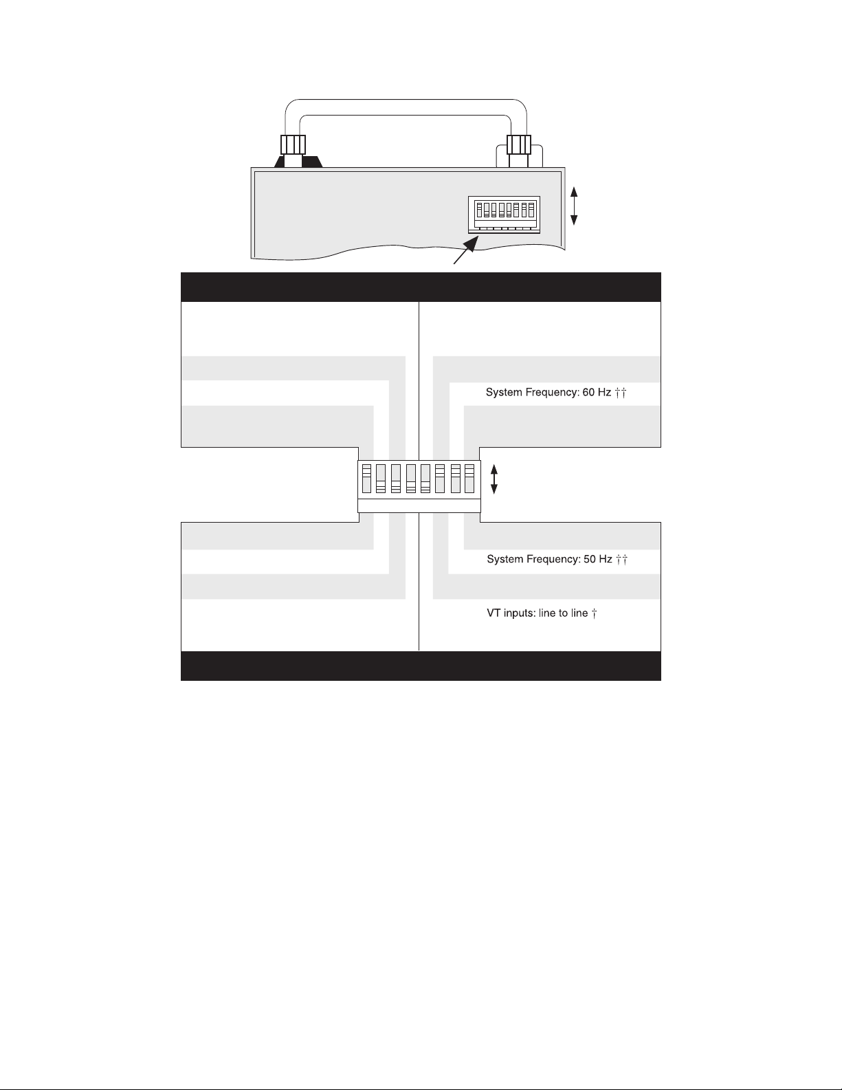
Installation – 6
Bottom view of M-0420 unit,
removed from pull-out case.
Reverse Power Initiation:
PA + PB + PC < setpoint
Directional Current:
Ia, Ib, and Ic > setpoint
Diagnostic Mode
Calibrate Relay
Not for user selection.
This switch must be set OFF.
Not for user selection.
This switch must be set OFF.
Normal Operation
Normal Operation
OFF (UP)
4
3
2
1
1 2 3 4 5 6 7 8
1
2
3
OFF
1 2 3 4 5 6 7 8
VT inputs: line to ground
5
VT secondary voltage: 120 V ac
6
ON
7
RMS magnitude calculated by
8
fundamental frequency
component only *
OFF
ON
RMS magnitude calculated by total
8
waveform (including harmonics) *
7
VT secondary voltage: 69.3 V ac **
6
Reverse Power Initiation:
PA or PB or PC < setpoint
Directional Current:
Ia or Ib or Ic > setpoint
4
ON (DOWN)
5
■ NOTES:
* 59N and 27N functions respond to fundamental frequency component of input waveform only,
regardless of the position of switch 8.
** When 69.3 V is chosen for the VT secondary voltage, 69.3 V is internally converted to 120 V (1 pu)
for all calculations and for setting and display options.
j If line-to-line is chosen for the basic VT inputs (DIP switch 5 is ON), reverse power sensing will
respond to total three-phase power regardless of the setting of switch 4.
jj If the system frequency selection (DIP switch 7) is changed from the original factory calibration, the
unit must be recalibrated (see the self-calibration procedure in Chapter 7, Test Procedures).
Figure 6-1 Internal Configuration DIP Switch–60 Hz.
6–5
Page 98
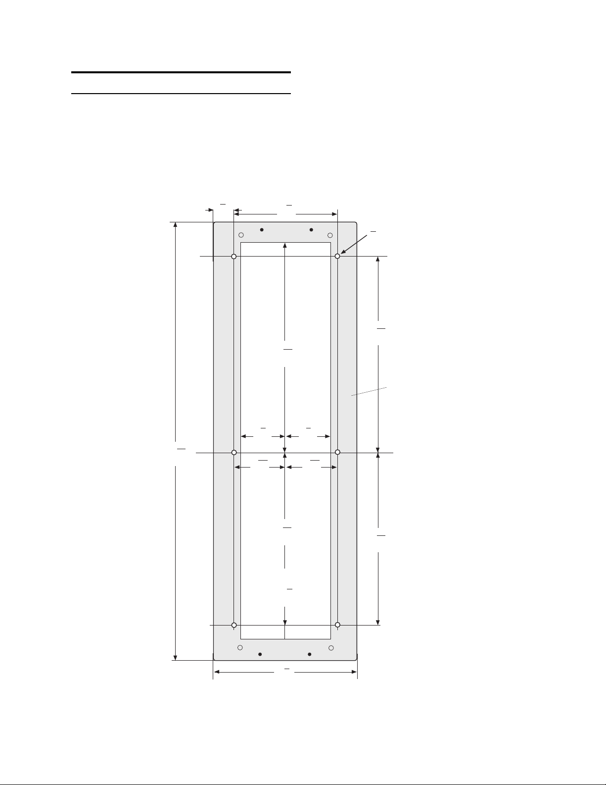
M-0420 Instruction Book
6.4 Mechanical/Physical Dimensions
The M-0420 Multifunction Relay is designed as a
drawout case for semiflush panel mounting. It will
directly mount in a panel prepared for either a
General Electric L-2 or Westinghouse FT-41 housing. Dimensions for these mounting configurations
are provided in Figures 6-2 and 6-3.
3
4
(1.9)
6
(15.6)
8
(22.7)
■ NOTE: If this is a new installation, choose
either mounting configuration and prepare the panel
accordingly.
1
8
1
4
Diameter
(0.64)
25
7
32
15
16
(19.8)
M-0420
Case Bezel
20
(52.8)
7
2
8
25
32
(7.2)
3
(7.8)
1
16
(22.7)
7
2
8
(7.2)
1
3
16
(7.8)
15
8
16
25
7
32
(19.8)
Max. Depth:
1
14
8
(35.9)
5
7
8
(19.4)
Inches
(Centimeters)
Front View
6–6
Figure 6-2 Mounting Dimensions for GE L-2 Cabinet
Page 99
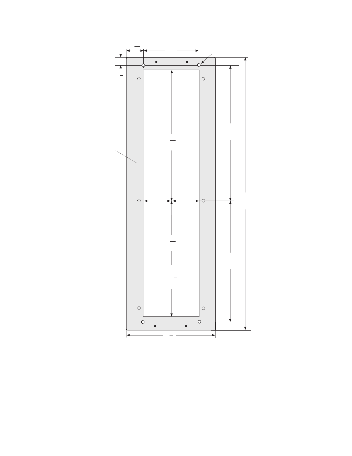
Installation – 6
M-0420
Case
Bezel
1
(2.9)
1
1
32
(2.6)
1
8
2
(7.2)
9
5
16
(14.1)
15
8
16
(22.7)
7
8
7
2
8
(7.2)
1
4
(0.64)
Diameter
1
9
4
(23.5)
25
20
32
(52.8)
15
8
16
(22.7)
1
9
4
(23.5)
Max. Depth:
1
14
8
(35.9)
5
7
8
(19.4)
Inches
(Centimeters)
Front View
Figure 6-3 Mounting Dimensions for Westinghouse FT-41 Cabinet
6–7
Page 100
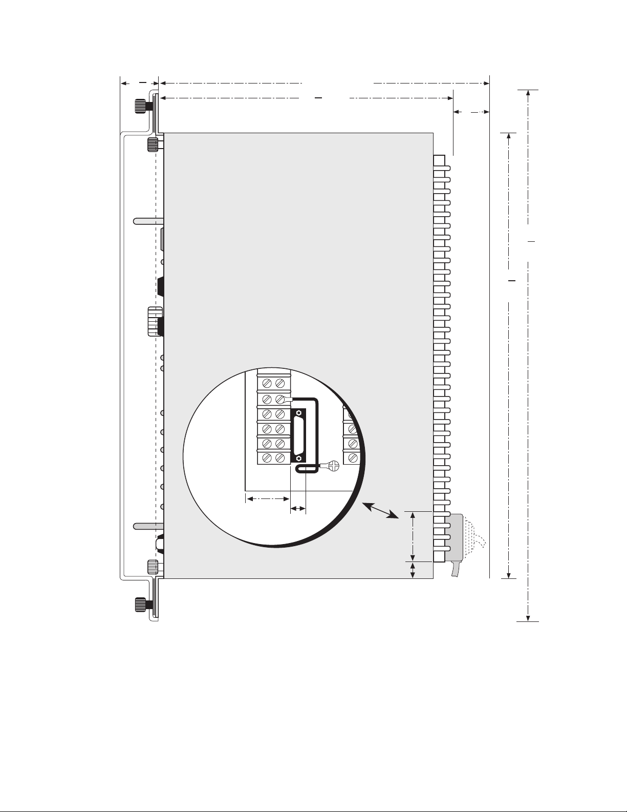
M-0420 Instruction Book
1
(3.8)
1
2
Approx.
1
14
2
19
(36.8)
(48.3)
Approx.*
1
4
2
(11.4)
17
(45.4)
Approx.
21
(53.7)
7
8
1
8
C
O
M
2
1.79
(6.4)
0.651
(1.65)
0.995
2.25
(5.72)
(2.53)
Inches
(Centimeters)
■ NOTE: Approximately 2.5" clearance is required when a right-angle connector is used for the rear
RS-232C port.
Figure 6-4 M-0420 Side View
6–8
 Loading...