

Page 1
Instruction Book
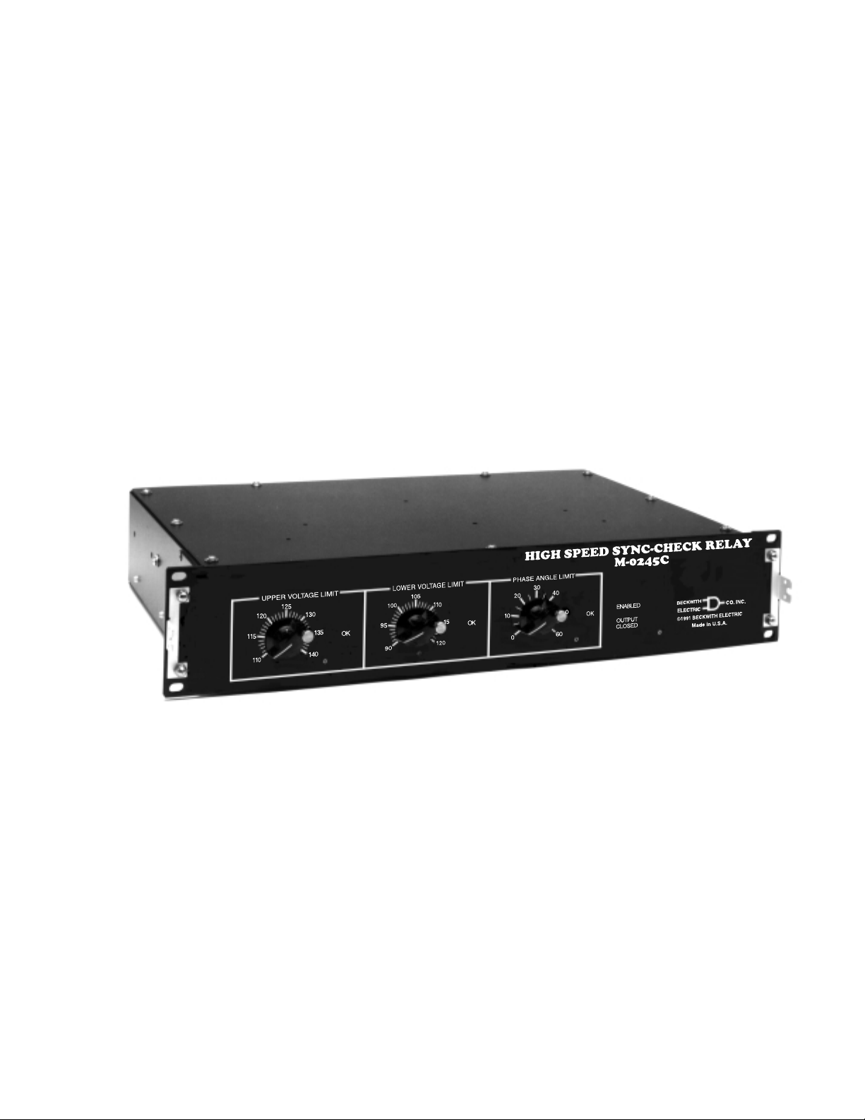
M-0245C High Speed
Sync-Check Relay
Page 2
SYNCHRONIZING
High Speed
Sync-Check Relay
M-0245C
Motor Bus Transfer Relay for
Power Plant and Industrial Site Motor Bus Transfer
• Verifies that the line voltage is within preset limits.
• Verifies within one cycle if the phase angle is within preset limits.
Page 3

M-0245C High Speed Sync-Check Relay Specification
High speed transfer of auxiliary services at a generating plant or the motor load in an industrial plant is highly
desirable to prevent either damage to critical motors or an unplanned shutdown.
A significant induced voltage will remain at the terminals of a rotating machine for a period of time following
removal of power. If, during the power transfer sequence, the phase angle of this voltage relative to the auxiliary
source is ignored, severe damage to an expensive machine or process may result. The M-0245C High Speed
Sync-Check Relay provides the means necessary to inhibit transfer if the phase angle is excessive or the line
voltage is out of range.
Inputs
Motor Bus Voltage: 120 V ac nominal
Line Voltage: 120 V ac nominal
M-0245C Supply: 120 V ac ±10%, 60 to 400 Hz
External Dry Contact Closure: Enables the synchronizing verification. This contact should be designed for low
voltage, low current signals.
■■
■ NOTE: All voltage inputs are isolated. The supply input and auxiliary source may be connected together
■■
externally, provided the voltage transformer from this auxiliary supply has sufficient capacity.
Burden
Motor Bus Voltage: 0.15 VA burden
Line Voltage: 0.15 VA burden
M-0245C Supply: 12 VA burden
Controls
UPPER VOLTAGE LIMIT for Line Voltage: 110 to 140 V ac
LOWER VOLTAGE LIMIT for Line Voltage: 90 to 120 V ac
PHASE ANGLE LIMIT: Ranges are available from 0 to 180°, 0 to 120°, 0 to 60°, or 0 to 30°
■■
■ NOTE: Accurately calibrated dials facilitate field adjustment without additional test equipment.
■■
LED Indicators
UPPER VOLTAGE LIMIT - OK: Line voltage is less than the upper voltage limit setting.
LOWER VOLTAGE LIMIT - OK: Line voltage is greater than the lower voltage limit setting.
PHASE ANGLE LIMIT OK: Phase difference between the Line and Bus voltage inputs is less than the phase
angle limit setting.
ENABLED: The external enable contact, rear terminal TB1-20 to TB1-21, is closed.
OUTPUT CLOSED: The solid-state output circuit, rear terminal TB2-A to TB2-B, is closed.
Breaker Close Relay
Solid-state Breaker Close Circuit is capable of making and breaking an inductive current of 15 A at 300 V dc. The
closing signal will remain until the enable contact is opened, provided phase angle and voltage remain within
preset limits.
Response Time
Delay after power turn on: Approximately 2 sec. Output will be open during this period, regardless of other
inputs.
Delay after closing enable input: 1/4 cycle. Output will be open until the M-0245C is enabled, regardless of
other inputs.
–2–
Page 4

M-0245C High Speed Sync-Check Relay Specification
Delay after voltage change in or out of band: Generally ranges from 0 to 0.08 sec. Refer to the M-0245C
Application Guide for further details.
Maximum delay after phase change in or out of band: 1 cycle
Status Relay Contacts
Line Source Voltage OK: Contact is closed when the voltage is within the upper and lower voltage limit settings.
Phase Angle OK: Contact is closed when the phase angle between the Line and Motor Bus voltage inputs is
within the phase angle limit setting.
Analog Outputs
Phase Difference: 0 to 180° corresponding to 0 to 10 V dc (55.6 mV per degree)
Line Source Voltage: 0 to 140 V ac input corresponding to 0 to 7 V dc output
Motor Bus Source Voltage: 0 to 140 V ac input corresponding to 0 to 7 V dc output
■■
■ NOTE: Each analog output has an output impedance of 10 K referenced to rear terminal TB1-7. These outputs
■■
are suitable for use with existing or future supervisory control systems.
Reliability
The M-0245C High Speed Sync-Check Relay is assembled on a single glass-epoxy printed circuit board, thereby
eliminating the need for plug-in connectors. All semiconductor components are hermetically sealed and of the
highest and most reliable quality available. Highly stable instrument grade capacitors and resistors are used in
critical measurement circuits to minimize the possibility of error.
Transient Protection
All inputs and outputs are fully transient protected and will pass the ANSI C37.90.1-1989 Surge Withstand
Capability (SWC) Test. The Motor Bus and Line Input Voltages, Status Relay outputs, 120 V ac Power input and
Breaker Close Circuit output will withstand 1500 V ac, 60 Hz to chassis or instrument ground for one minute.
Voltage inputs are electrically isolated from each other, from other circuits and from ground.
■■
■ NOTE: Use of varistor suppressors across contacts and from contacts to chassis ground is suggested if
■■
these contacts are to be tied to long wire runs.
Harmonic Filters
Many applications for the M-0245C High Speed Sync-Check Relay will involve power systems which incorporate
loads such as variable speed drives, arc furnaces and converters which produce harmonics on the system. The
M-0245C includes active filters on the bus and line voltage inputs to permit proper operation in these applications.
Environmental
Temperature Range: Units will operate properly over a temperature range of –40° to +80° C.
Humidity: Stated accuracies are maintained under 95% relative humidity (non-condensing).
Fungus Resistance: A conformal printed circuit board coating inhibits fungus growth.
Seismic: Units are designed to meet extreme shock and vibration requirements.
–3–
Page 5

Physical
Size: 19" wide x 3-1/2" high x 13" deep (48.3 cm x 8.9 cm x 33.0 cm). Requires two rack units space in a
standard 19" rack. May also be panel-mounted horizontally or vertically.
Approximate Weight: 15 lbs (6.8 kg)
Approximate Shipping Weight: 20 lbs (9.1 kg)
The M-0245C includes a transparent cover to protect the knobs and prevent accidental resetting.
Patents
The M-0245C High Speed Sync-Check Relay is covered by U.S. Patents 4,218,625 and 4,256,972.
Warranty
The M-0245C High Speed Sync-Check Relay is covered by a two year warranty from date of shipment.
The Specification is subject to change without notice.
© Beckwith Electric Co.
Printed in U.S.A. (04.24.01)
BECKWITH ELECTRIC CO., INC.
6190 - 118th Avenue North • Largo, Florida 33773-3724 U.S.A.
PHONE (727) 544-2326 • FAX (727) 546-0121
E-MAIL [email protected]
WEB PAGE www.beckwithelectric.com
800-0245C-00 04/01
Page 6
WARNING
DANGEROUS VOLTAGES, capable of causing death or serious
injury, are present on the external terminals and inside the equipment. Use extreme caution and follow all safety rules when handling, testing or adjusting the equipment. However, these internal
voltage levels are no greater than the voltages applied to the external terminals.
DANGER! HIGH VOLTAGE
– This sign warns that the area is connected to a dangerous high voltage, and you
must never touch it.
PERSONNEL SAFETY PRECAUTIONS
The following general rules and other specific warnings throughout the manual must be followed during application,
test or repair of this equipment. Failure to do so will violate standards for safety in the design, manufacture, and intended
use of the product. Qualified personnel should be the only ones who operate and maintain this equipment. Beckwith
Electric Co., Inc. assumes no liability for the customer’s failure to comply with these requirements.
– This sign means that you should refer to the corresponding section of the operation
manual for important information before proceeding.
Always Ground the Equipment
To avoid possible shock hazard, the chassis must be connected to an electrical ground. When servicing
equipment in a test area, the Protective Earth Terminal must be attached to a separate ground securely
by use of a tool, since it is not grounded by external connectors.
Do NOT operate in an explosive environment
Do not operate this equipment in the presence of flammable or explosive gases or fumes. To do so would
risk a possible fire or explosion.
Keep away from live circuits
Operating personnel must not remove the cover or expose the printed circuit board while power is applied. In no case may components be replaced with power applied. In some instances, dangerous voltages may exist even when power is disconnected. To avoid electrical shock, always disconnect power and
discharge circuits before working on the unit.
Exercise care during installation, operation, & maintenance procedures
The equipment described in this manual contains voltages high enough to cause serious injury or death.
Only qualified personnel should install, operate, test, and maintain this equipment. Be sure that all personnel safety procedures are carefully followed. Exercise due care when operating or servicing alone.
Do not modify equipment
Do not perform any unauthorized modifications on this instrument. Return of the unit to a Beckwith
Electric repair facility is preferred. If authorized modifications are to be attempted, be sure to follow
replacement procedures carefully to assure that safety features are maintained.
Page 7

PRODUCT CAUTIONS
Before attempting any test, calibration, or maintenance procedure, personnel must be completely familiar
with the particular circuitry of this unit, and have an adequate understanding of field effect devices. If a
component is found to be defective, always follow replacement procedures carefully to that assure safety
features are maintained. Always replace components with those of equal or better quality as shown in the
Parts List of the Instruction Book.
Avoid static charge
This unit contains MOS circuitry, which can be damaged by improper test or rework procedures. Care
should be taken to avoid static charge on work surfaces and service personnel.
Use caution when measuring resistances
Any attempt to measure resistances between points on the printed circuit board, unless otherwise noted
in the Instruction Book, is likely to cause damage to the unit.
Page 8

Table of Contents
M-0245C High Speed Sync-Check Relay
Instruction Book
1.0 Introduction ................................................................................................................... 1
2.0 Theory of Operation...................................................................................................... 1
Motor Bus Undervoltage Monitor .................................................................................. 1
Input Loss Protection .................................................................................................... 1
3.0 Maintenance ................................................................................................................. 2
Figure 1 Block Diagram .............................................................................................
4.0 Test Procedure ............................................................................................................. 4
Equipment Required ..................................................................................................... 4
4.1 Component Replacement Procedure ........................................................................... 4
3
4.2 Test Procedures ........................................................................................................... 4
Upper Voltage Limit ...................................................................................................... 4
Lower Voltage Limit ...................................................................................................... 4
Phase Angle Limit......................................................................................................... 5
Voltage Analog Output.................................................................................................. 5
Phase Angle Analog Output ......................................................................................... 5
Voltage Status Output Contact ..................................................................................... 5
Figure 2 External Connections ...................................................................................
Phase Angle Status Output .......................................................................................... 7
Breaker Close Circuit.................................................................................................... 7
Enable Response Time ................................................................................................ 7
Phase Angle OK to Output Contact Response Time .................................................... 8
4.3 Phase Angle Detection Circuit ...................................................................................... 8
Rate of Change of Phase Angle ................................................................................... 8
4.4 Loss of Voltage Input Detection Circuits ....................................................................... 8
Line Voltage Loss ......................................................................................................... 8
Motor Bus Voltage Loss ............................................................................................... 8
Motor Bus Undervoltage Detector <25% ...................................................................... 8
Figure 3 Test Setup ...................................................................................................
Figure 4 Line Voltage Loss ......................................................................................
Figure 5 Motor Bus Voltage Loss .............................................................................
10
10
6
9
5.0 Typical Voltages ......................................................................................................... 11
Conditions................................................................................................................... 11
6.0 Typical Resistances ................................................................................................... 12
Conditions................................................................................................................... 12
–i–
Page 9

7.0 Calibration ..................................................................................................................13
Phase Angle Calibration ............................................................................................. 13
Figure 6 Component Location, B-0207 ....................................................................
Figure 7 Variable Speed Motor Application Option Component Location ................
Figure 8 Schematic, X-0245 ....................................................................................
Figure 9 Variable Speed Motor Application Option Schematic, Y-0264 ...................
14
15
16
18
Parts List .................................................................................................................... 19
Phase Angle Limit Control Option............................................................................... 25
Parts Mounted to the Enclosure ................................................................................. 25
B-0264 Variable Speed Motor Application Option ...................................................... 26
© Beckwith Electric Co.
Printed in U.S.A. (04.24.01)
800-0245C-IB-00 04/01
–ii–
Page 10

1.0 Introduction
The Beckwith Electric M-0245C is a solid-state device
specifically designed to respond to changes in the
phase angle between two input voltages. When the
line voltage input is within the UPPER and LOWER
VOLTAGE LIMIT dial settings, and the phase angle
between the line voltage and the motor bus voltage is
less than that set on the PHASE ANGLE LIMIT dial,
the device will permit breaker closing. If the phase
angle exceeds the control setting, the device will
block closing within one cycle; i.e., if the limit is 30°,
the unit will inhibit closing within one cycle of the time
when the phase angle exceeds 30°. If the phase
angle returns within the 30° limit, the unit will enable
closing within one cycle.
Using advanced, state of the art semiconductors and
circuits, the Beckwith Electric M-0245C achieves an
overall stability and resolution unattainable with other
techniques. Modern hybrid and monolithic
semiconductors are used to gain temperature stability
without critical compensation or trimming. Unique,
patented circuitry allows precise phase measurement
over a wide range of frequency, voltage and
temperature; while operating within ±1% of the
theoretical speed limit for phase measurement.
2.0 Theory of Operation
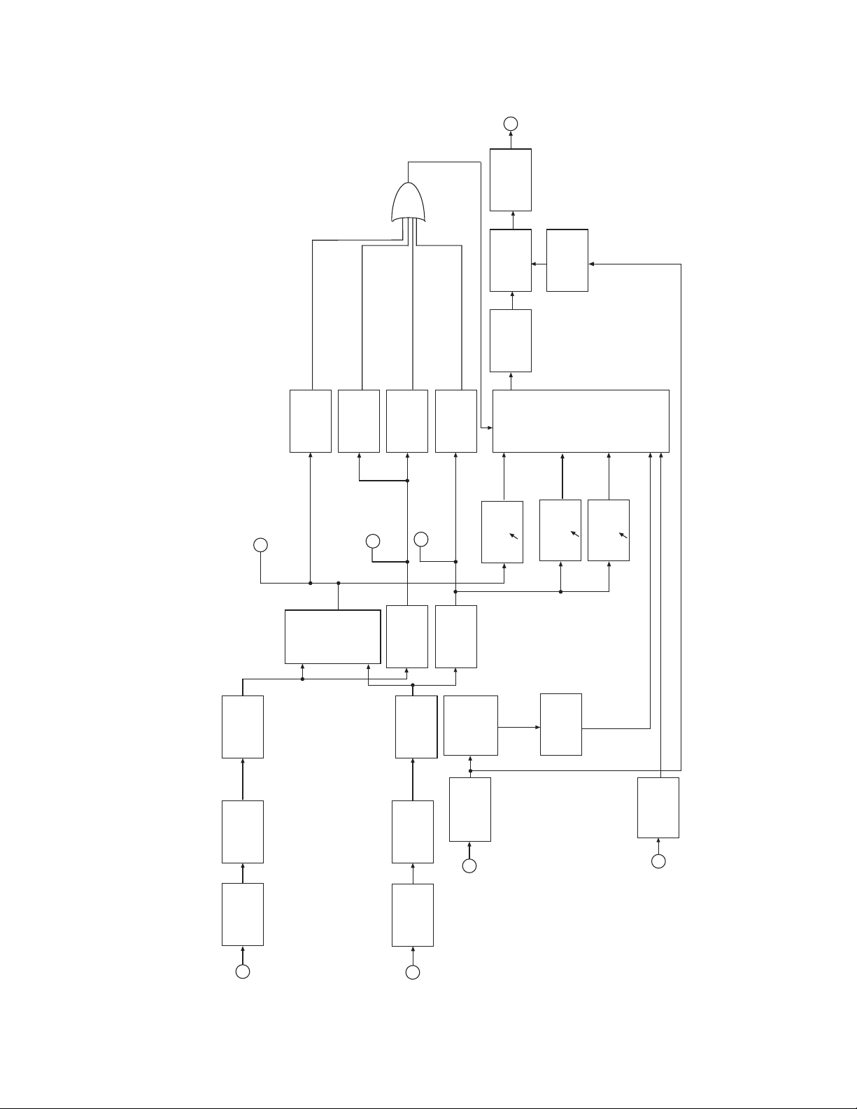
Refer to Figure 1, Block Diagram. Each input (Motor
Bus, Line) is passed through a transformer and scaled
down from 120 V ac to 6 V ac. If variable speed motor
control is used on the motor bus, the variable speed
motor application option should be specified, which
places a dual channel low pass active filter after each
input transformer. This eliminates false zero crossing
triggering due to commutated bus voltage waveforms.
The scaled down voltages are converted into dc
voltages by the Ac to Dc Converters. These converters
are active full-wave rectifiers and filters that eliminate
the diode drop typical of conventional full-wave
rectifiers, which are highly temperature-dependent.
Full-wave rectification was chosen over half-wave
rectification because the filter response time is much
faster for a given ripple voltage. This is due to the fact
that full-wave rectification contains no fundamental
frequency components, only harmonics. The Upper
and Lower Voltage Comparitors compare the output
of the Ac to Dc Converter to a portion of a highly
stable hybrid 10 V reference. LEDs located on the
front panel indicate the condition of the Line voltage
with reference to the UPPER and LOWER VOLTAGE
LIMIT settings.
Two Zero-Crossing Detectors generate rectangular
waveforms at the zero crossing of each input. A logic
gate provides a pulse width that is proportional to the
phase difference between each input, which is then
integrated and sampled each half cycle of the highest
frequency input. This sampled voltage is an accurate
measure of the phase difference and is updated
once every 8.3 ms. The sampled voltage varies from
0 to +10 V for a phase difference change of 0 to
±180°. The sampled phase voltage is compared to
the extremely stable hybrid voltage reference. The
compared signal is an indication of the phase
difference with reference to the front panel PHASE
ANGLE LIMIT setting. Rear terminal TB1-5 allows
external monitoring of the phase difference sampled
voltage, referenced as “Phase Angle Analog Output.”
Power is provided by the Power Supply, which
supplies ±24 V dc, ±15 V dc and the precision 10 V
reference used for comparison. The supply is
designed to operate from 108 V ac to 132 V ac input
and is electrically isolated from all other inputs and
outputs. The Logic Network monitors all functions
including power supply voltages. Upon receiving a
logic “1” from the enable input and the appropriate
logic conditions from the Phase Angle, Upper Voltage,
and Lower Voltage Comparitors; the Logic Network
outputs a breaker close signal to the Breaker Close
Network. Terminals A and B are electrically shorted
by the Breaker Close Network until one of the
controlling logic conditions is false or logic “1.”
Motor Bus Undervoltage Monitor
The Motor Bus Undervoltage Detector will disable
the relay if the voltage decays below 25% during a
bus transfer sequence. This will ensure that the phase
measurement circuitry does not misoperate during a
low voltage condition.
Input Loss Protection
The M-0245C has been designed with an Input Loss
Detector circuit to minimize the possibility of the output
contacts closing due to sudden loss of the VT input
sources. The M-0245C output contact is forced to
the normally open state for any of the following
conditions:
1. Sudden drop in the line V.T. voltage
magnitude.
2. Sudden drop in the bus V.T. voltage
magnitude.
3. Bus V.T. voltage less than 0.25%.
4. Rate of change of phase, as detected by
the M-0245C circuitry, is greater than
2900°/sec. (8 Hz frequency difference).
–1–
Page 11

M-0245C Instruction Book
The possibility still remains, however, that under certain
conditions (i.e., loose wires causing an intermittent
contact) the internal circuitry may not be able to
detect the loss, and the output contact could close
when the unit is initiated. Therefore, as a safeguard,
the “Close to Enable Sync Check” contact from TB120 to TB1-21 should be closed only during the time
required for the transfer sequence to be completed.
3.0 Maintenance
Due to the extremely sophisticated nature of the
circuitry in the M-0245C, field repair is not
recommended. All units are fully calibrated at the
factory prior to shipment; there is no need to recalibrate a unit prior to initial installation. Calibration
is only required after a component is replaced.
In the event that a unit does not operate properly, it
should be established that the problem is caused by
malfunction of a Beckwith Electric unit and not caused
by an external fault or wiring error. Once this is
determined, the entire unit should be returned to
Beckwith Electric. Pack the unit carefully (in the
original carton if possible), assuring that there is
adequate packing material to protect the contents.
■ NOTE: Any equipment returned for repair must
be sent with transportation charges
prepaid. The equipment must remain the
property of the user. The warranty is void
if the value of the unit is invoiced to
Beckwith Electric at the time of return or if
the unit is returned with transportation
charges collect.
If under warranty, units will be repaired rapidly and
returned at no cost and with return transportation paid
if the fault is found to be due to workmanship or failure
of material. If a unit is under warranty and express
shipment for return of the repaired unit is requested,
shipping charges will be billed at the current rate. If
the fault is due to abuse or misuse, or if the unit is out
of warranty, a modest charge will be made. Repair
can normally be expected to take two weeks, plus
shipping time. If faster service is required, it should
be requested at the time of return.
To help in analyzing the problem, a complete
description of the malfunction and conditions leading
to the failure should be included with the unit.
However, if you choose to repair the unit, it is
necessary to be completely familiar with the circuitry
involved, and have an adequate understanding of
field effect devices. Be sure to carefully read the
WARNING page at the beginning of this manual.
To gain access to the circuit board, remove the top
and bottom cover of the unit. Components can then
be easily tested or changed. It is suggested that first
a visual inspection be made for any component that
does not appear normal or appears to have
overheated. Analysis of the circuit will then often lead
to the cause of the failure and components that need
to be replaced.
If no obvious problems exist, it is suggested that the
TEST and CALIBRATION PROCEDURES be
followed until a portion of a circuit is detected which
does not perform as expected or until a calibration
point is found which will not meet requirements. These
procedures should lead to a determination of the
defective component.
▲ CAUTION: Do not reverse polarity of the V.T.
leads to the rear terminal block if the unit is taken out
of service for maintenance.
–2–
Page 12
CLOSE
OUTPUT
BREAKER
TRANSIENT
1 V/18°
PHASE ANGLE
ANALOG OUTPUT
RATE OF
CHANGE OF
Ø > 2900°/sec
PHASE
HIGH-SPEED
<25%
VOLTAGE
DETECTOR
BUS UNDER-
1 V/20 V ac
BUS VOLTAGE
ANALOG OUTPUT
NETWORK
MEASURING
DETECTOR
INPUT LOSS
1 V/20 V ac
LINE VOLTAGE
ANALOG OUTPUT
1 V/20 V ac
ACTIVE
AC to DC
CONVERTER
BLOCK CLOSING
DETECTOR
INPUT LOSS
1 V/20 V ac
ACTIVE
AC to DC
CONVERTER
CLOSE
BREAKER
NETWORK
SOLID-STATE
OPTICAL
PHASE OK
PHASE ANGLE
COMPARATOR
POWER
ISOLATED
UPPER
VOLTAGE
COMPARATOR
SUPPLY
LOGIC
NETWORK
LOWER
VOLTAGE
COMPARATOR
SPEED
MOTOR
VARIABLE
ISOLATION
STEP-DOWN
TRANSFORMER
TRANSIENT
PROTECTION
BUS
INPUT
MOTOR
MAIN
POWER
SPEED
MOTOR
VARIABLE
ISOLATION
STEP-DOWN
TRANSFORMER
TRANSIENT
PROTECTION
LINE
INPUT
SUPPLY
TRANSIENT
PROTECTION
60 Hz
120 VAC
NETWORK
Figure 1 Block Diagram
–3–
POWER
SUPPLY
MONITOR
BUFFER
AMPLIFIER
INPUT
ENABLE
SYNC-CHECK
Page 13

M-0245C Instruction Book
4.0 Test Procedure
■■
■ NOTE: Values that change for the 50 Hz Operation
■■
option are shown in brackets.
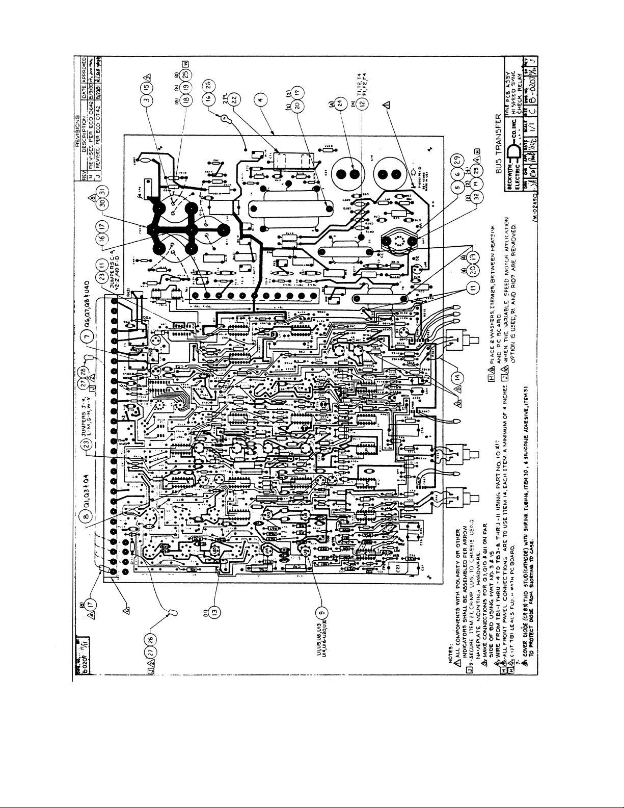
Refer to Figure 2, External Connections, and Figure 6,
Component Location, in conjunction with this section.
Equipment Required
1. A variable frequency source with phase
angle control capable of providing 140 V
rms with a minimum phase setting
resolution of 1°.
2. A fixed 60 [50] Hz frequency source
capable of providing 140 V rms with a
minimum phase setting resolution of 1°
rms.
3. Two (2) digital multimeters (DMMs) with
ac and dc accuracy of ±0.2% of full scale;
Hewlett-Packard model 3465A or
equivalent.
4. A dual trace oscilloscope; Tektronics, Inc.
model 465 or equivalent.
5. A digital phase angle meter with an
accuracy of ±0.5°.
6. A synchroscope, if available.
7. An incandescent bulb and dc battery
source.
■ NOTE: The two ac sources above should be
phase-locked to each other.
4. When replacing integrated circuits, make
sure to insert the unit into the transipad so
that the tab fits into the slot. Once this is
done, there is only one way to insert the
combination into the printed circuit board.
5. Use a Weller Controlled Output Soldering
Station, model MTCPL, 60 W, 120 V,
50/60 Hz with a grounded tip or equivalent
equipment when soldering in new
components.
4.2 Test Procedure
Upper Voltage Limit
1. Set the UPPER VOLTAGE LIMIT control
to 125 V rms.
2. Apply the variable source at 120 V rms,
60 [50] Hz to TB1-1 and TB1-2. Note that
TB1-1 is the Hot terminal. This source will
later be referred to as the “Motor Bus
voltage input.”
3. Apply the fixed source at 120 V rms, 60
[50] Hz to TB1-3 and TB1-4, and TB1-26
and TB1-27. Note that TB1-4 and TB1-27
are the Hot terminals. This source will
later be referred to as the “Line voltage
input.”
4. The UPPER VOLTAGE LIMIT-LINE LED
should light.
5. Slowly raise the Line voltage input to
approximately 125 V rms.
4.1 Component Replacement
Procedure
1. The M-0245C printed circuit board has been
coated with a moisture-resistant, conformal
coating. If a component needs to be
changed, carefully scrape away the coating
surrounding the component using a small,
sharp knife; being careful not to damage
the foil on the printed circuit board.
2. Clip out the old component and discard.
▲ CAUTION: Do not attempt to melt the solder and
push the new component through the hole, as the
leads are likely to catch the edge of the foil and lift it
off the board.
3. Remove the clipped wires using a solder
wick or syringe. Be sure to leave the holes
clear to facilitate insertion of the new
component.
6. The UPPER VOLTAGE LIMIT-LINE LED
should go out as the Line voltage passes
125 V rms.
7. Slowly reduce the Line voltage input; the
UPPER VOLTAGE LIMIT-LINE LED
should light as the voltage level drops
below 125 V rms.
8. Return the Line voltage input to 120 V
rms.
9. Repeat steps 3 through 7 with the UPPER
VOLTAGE LIMIT dial set at 115 V rms,
then at 135 V rms.
Lower Voltage Limit
1. Set the LOWER VOLTAGE LIMIT dial at
105 V rms.
2. Adjust the Line voltage input to
approximately 106 V rms.
3. Adjust the Bus voltage input to 120 V rms.
–4–
Page 14

■ NOTE: To prevent the voltage level detection
circuit outputs from oscillating, there is
approximately 0.5 V rms hysteresis
between when the LEDs turn on and turn
off, within a dial setting accuracy of K2%
of full scale.
4. The LOWER VOLTAGE-LINE LED should
light.
5. Slowly reduce the Line voltage; the LOWER
VOLTAGE LIMIT-LINE LED should go out
as the Line voltage input drops below 105
V rms.
6. Slowly increase the Line voltage input; the
LOWER VOLTAGE LIMIT-LINE LED
should light as the voltage level passes
105 V rms.
7. Return the Line voltage input to 120 V rms.
8. Repeat steps 3 through 6 with the LOWER
VOLTAGE LIMIT set at 95 V rms, then at
115 V rms.
Phase Angle Limit
■ NOTE: The following section is written for a 60°
full scale unit. Multiply accordingly for other
scale options.
1. Adjust the Line voltage input to 120 V rms,
60 [50] Hz.
2. Adjust the Motor Bus voltage input to 120 V
rms, 60 [50] Hz.
3. The phase angle meter reading and
synchroscope should show a stable phase
angle.
4. Set the PHASE ANGLE LIMIT dial at
midscale (30°).
5. Adjust the phase angle between the Line
and Motor Bus voltage inputs to 29.5°.
■ NOTE: To prevent the voltage level detection
circuit outputs from oscillating, there is
approximately 0.5 V rms hysteresis
between when the LEDs turn on and turn
off, within a dial setting accuracy of K2%
of full scale.
9. Repeat steps 4 through 8 with the PHASE
ANGLE LIMIT dial set at 10° and 50°.
10. Return both inputs to 120 V rms, 60
[50] Hz.
Voltage Analog Output
1. Connect the positive lead of the multimeter
to TB1-28.
2. Connect the negative (common) lead of
the multimeter to TB1-7.
3. The dc voltage reading should be
proportional to the Line voltage input ac
level, which should be 0 to 7 V dc as the
Line voltage input varies from 0 to 140 V
rms. The accuracy should be K2% of full
scale.
4. Move the DMM positive lead from TB1-28
to TB1-18. The negative lead remains on
TB1-7.
5. The dc voltage reading should be 0 to 7 V
dc as the Motor Bus voltage input varies
from 0 to 140 V rms. The accuracy should
be ±2% of full scale.
Phase Angle Analog Output
1. Connect the DMM positive lead to TB1-5.
2. Connect the DMM negative lead to TB1-7.
3. The dc voltage reading should be 0 to 10
V dc as the phase angle between the Line
input and the Motor Bus input changes
from 0° to 180°. The accuracy should be
±1% of full scale.
Voltage Status Output Contact
1. Place one ohmmeter across TB1-22 and
TB1-23.
2. Set the UPPER VOLTAGE LIMIT dial at
125 V rms.
3. Set the LOWER VOLTAGE LIMIT dial at
105 V rms.
4. Adjust the Motor Bus voltage input level to
120 V rms, 60 [50] Hz.
5. Adjust the Line voltage input level to 120 V
rms, 60 [50] Hz.
6. The PHASE ANGLE OK LED should light.
7. Slowly increase the phase angle between
the sources; the PHASE ANGLE OK LED
should go out as the phase angle passes
30°.
8. Slowly reduce the phase angle; the
PHASE ANGLE OK LED should come on
as the phase angle drops below 30°.
6. The VOLTAGE LIMIT LED should be lit.
7. The Voltage Status Contact from TB1-22
to TB1-23 should be closed.
8. Set the UPPER VOLTAGE LIMIT dial to
115 V rms.
9. The Voltage Status Contact from TB1-22
to TB1-23 should open when the UPPER
VOLTAGE LIMIT-LINE LED is off.
–5–
Page 15
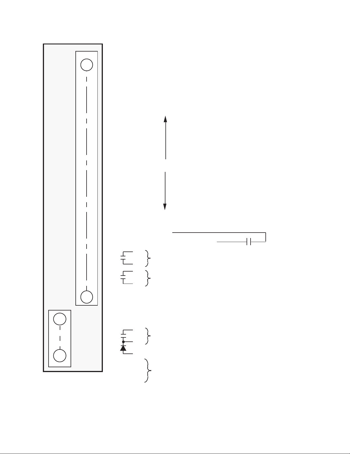
M-0245C Instruction Book
1
10
11
12
FUNCTION
1
Motor Bus Potential Input Hot
2
Motor Bus Potential Input Neutral
3
Line Potential Input Neutral
4
Line Potential Input Hot
5
Phase Angle Analog Output
6
Not used
7
0 Volts, Common for Analog Outputs. Should be Grounded.
8
9
13
14
15
16
17
18
19
20
21
22
23
24
25
TB1
28
AH
26
27
28
Not Used
Motor Bus Voltage Analog
Output
0 Volts
Enable Sync-Check Input
Status Contact, Closed
when Voltage OK
Status Contact, Closed when
Phase Angle OK
120 V ac Power Neutral
120 V ac Power Hot
Line Voltage Analog Output
Close to Enable
Sync-Check
TB2
+
A
Solid-State Breaker Close Circuit Output
B
-
C
Transient Suppressor Diode
D
Not Used
H
Figure 2 External Connections
–6–
Page 16

10. Return the UPPER VOLTAGE LIMIT dial
to 125 V rms.
11. The UPPER VOLTAGE LIMIT-LINE LED
should be on, and the Voltage Status
Contact from TB1-22 to TB1-23 should be
closed.
12. Move the LOWER VOLTAGE LIMIT dial
past 115 V rms to approximately 118 V
rms.
13. The Voltage Status Contact from TB1-22
to TB1-23 should be open when the LOWER
VOLTAGE LIMIT-LINE LED is off.
14. Return the LOWER VOLTAGE LIMIT dial
to 105 V rms.
15. The LOWER VOLTAGE LIMIT-LINE LED
should be on, and the Voltage Status
Contact should be closed.
Phase Angle Status Output
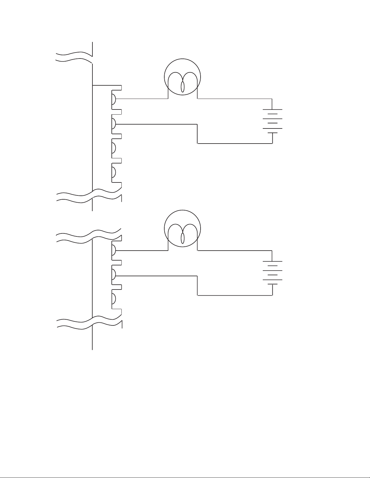
1. Connect a 25 W incandescent bulb and a
dc battery source across Phase Angle
Status Contact TB1-24 and TB1-25 as
shown in Figure 3, Test Setup.
2. Adjust the Line voltage input to 120 V rms,
60 [50] Hz.
3. Adjust the Motor Bus voltage input to 120
V rms, 60 [50] Hz at a 20° phase angle
with respect to the Line voltage input.
4. Set the the UPPER VOLTAGE LIMIT dial
to 125 V rms.
5. Set the LOWER VOLTAGE LIMIT dial to
105 V rms.
6. Set the PHASE ANGLE LIMIT dial to 30°.
7. Slowly increase the phase angle between
the Line and Motor Bus voltage inputs.
8. The PHASE ANGLE OK LED and the
light bulb should turn off as the phase
angle passes 30°.
9. Slowly reduce the phase angle between
the sources to below 30°; the light bulb
and the LED should light as the phase
angle passes 30°.
3. With the phase angle between the inputs
at 20° and the PHASE ANGLE LIMIT dial
set at midscale, the incandescent bulb
and all front panel LEDs should light.
4. Slowly increase the phase angle above
30°, the light bulb and the PHASE ANGLE
OK LED should turn off.
5. Return the phase angle between the
sources to 20°.
6. The incandescent bulb should be lit.
7. Remove the jumper from the Enable Sync
Check Input TB1-20 to TB1-21.
8. The output should drop out (the bulb should
turn off) when the jumper is removed and
should light when the jumper is reapplied.
Enable Response Time
1. Adjust the Line voltage input to 120 V rms,
60 [50] Hz.
2. Adjust the Motor Bus voltage input to 120
V rms at a 20° phase angle with respect to
the Line input.
3. Place the Channel 1 scope probe on
TB1-20 and the reference on TB1-21.
4. Place the Channel 2 scope probe on
TB2-A and the reference on TB2-B.
5. Set the scope trigger mode on “Normal.”
6. Set the trigger slope level on (+).
7. Set the trigger source on Channel 1.
8. Set the horizontal sweep time at 2 ms/div.
9. Test the Enable Sync Check Input
terminals TB1-20 and TB1-21 with a
jumper to ensure proper trigger of the
sweep. Adjust the stop level dial towards
the (+) direction to observe better starting
point of the sweep. Adjust the horizontal
position, if necessary.
10. After proper triggering of the signal is
observed when the unit is enabled, push
the vertical mode to Channel 2 to monitor
the signal on the Breaker Close Circuit
Output.
Breaker Close Circuit
1. Connect an incandescent bulb and a dc
battery source to the Breaker Close Circuit
Output TB2-A and TB2-B as shown in
Figure 3. Note that TB2-A is the more
positive terminal.
2. Adjust the Line voltage and Motor Bus
voltage inputs to 120 V rms, 60 [50] Hz.
11. Measure the delay time between when
the Enable Sync Check Input closes and
the Breaker Close Circuit Output TB2-A
and TB2-B signal drops to minimum by
counting the divisions on the horizontal
screen.
12. The response time between when the
Enable Sync Check Input closes and the
Breaker Close Circuit Output closes should
be approximately 5 ms K2 ms.
–7–
Page 17

M-0245C Instruction Book
Phase Angle OK to Output Contact Response
Time
1. Set the PHASE ANGLE LIMIT dial to 20°.
2. Apply 120 V rms, 60 [50] Hz to the Line
voltage input.
3. Apply 120 V rms, 60 [50] Hz to the Motor
Bus voltage input at a 40° phase angle
with respect to the Line voltage input.
4. Attach the Channel 1 scope probe to CR64
cathode, with reference to TB1-7.
5. Change the scope trigger to trigger on a
decrease in phase angle.
6. Channel 2 should remain attached to
TB2-A and TB2-B.
7. Jump the phase angle to 0°.
8. Measure the time delay between the
change in phase angle and the Channel 2
signal going high.
9. The time delay should be 7 ms (minimum)
to 24 ms (maximum).
10. Change the scope trigger to trigger on an
increase in phase angle.
4.4 Loss of Voltage Input
Detection Circuits
Line Voltage Loss
Refer to Figure 4, Line Voltage Loss, for the following
section:
1. Apply 120 V ac, 60 [50] Hz to the Bus
voltage input.
2. Apply 120 V ac, 60 [50] Hz to the Line
voltage input.
3. Place the Channel 1 probe on the anode
of CR19.
4. Place the Channel 2 probe on the end of
R136 nearest the rear terminal block.
5. Trigger the scope on Channel 1. Set the
horizontal sweep time at 5 ms/div.
6. Completely remove the Line voltage inputs.
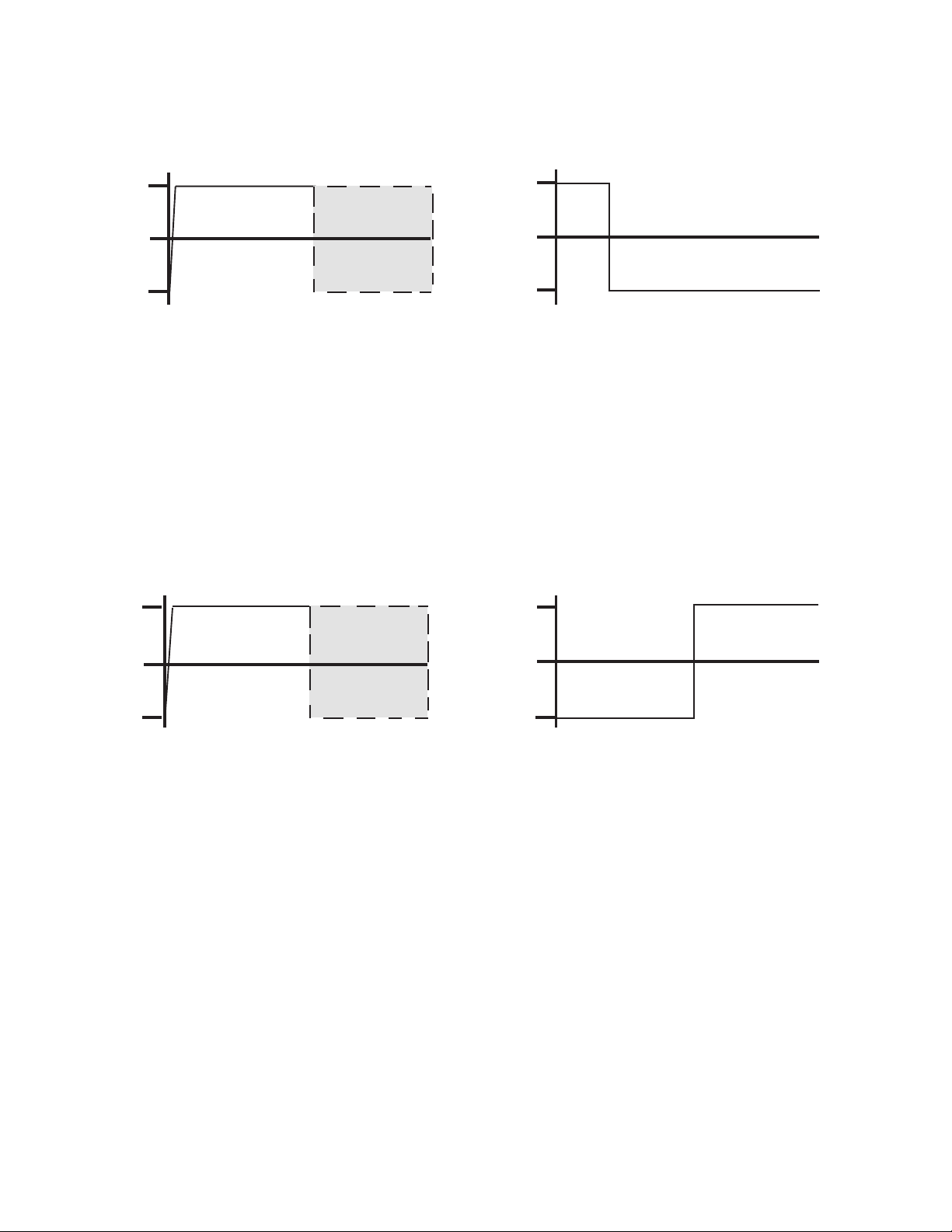
7. As shown in Figure 4, the Channel 1 signal
should immediately go high from –15 V to
+15 V, and Channel 2 should go low after
20 ms.
11. Jump the phase angle from 0° to 40°.
12. Measure the time delay between the phase
angle increasing and the output contact
opening.
13. The time delay should be 7 ms (minimum)
to 24 ms (maximum).
4.3 Phase Angle Detection Circuit
Rate of Change of Phase Angle
1. Apply 120 V ac, 60 [50] Hz to the Line
voltage input.
2. Attach the scope ground to the negative
end of C78; attach the probe to the anode
of CR8.
3. Begin to slowly adjust the Motor Bus
frequency to approximately 120 V ac,
51 Hz.
4. The pulse rate should be approximately
one pulse per cycle as the Motor Bus
frequency approaches 51 [41] Hz K1 Hz.
5. Slowly increase the Motor Bus frequency.
Pulses should stop as the frequency rises
above approximately 51 [41] Hz.
Motor Bus Voltage Loss
Refer to Figure 5 for the following section.
1. Apply 120 V ac, 60 [50] Hz to the Motor
Bus voltage input.
2. Apply 120 V ac, 60 [50] Hz to the Line
voltage input.
3. Place the Channel 1 probe on Test Point
10 (TP10); attach Channel 2 probe to TP9.
4. Trigger the scope on Channel 1. Set the
horizontal sweep time at 10 ms/div.
5. Completely remove the Motor Bus voltage
input.
6. As shown in Figure 5, the Channel 1 signal
should immediately go high from –15 V to
+15 V, and Channel 2 should go high after
approximately 50 ms.
Motor Bus Undervoltage Detector <25%
1. Reapply 120 V ac, 60 [50] Hz to the Motor
Bus voltage input.
2. Remove the Channel 1 probe.
3. Slowly reduce the Motor Bus voltage.
4. The signal on Channel 2 should go high
as the voltage level drops below 25%.
–8–
Page 18
M-0245
CONNECTIONS FOR BREAKER
CLOSE CIRCUIT TEST
25 W
INCANDESCENT
BULB
TB2-A
TB2-B
TB2-C
TB2-D
TB1-24
TB1-25
+
DC SOURCE
-
CONNECTIONS FOR PHASE ANGLE
STATUS CONTACT TEST
25 W
INCANDESCENT
BULB
+
DC SOURCE
TB1-26
-
Figure 3 Test Setup
–9–
Page 19
M-0245C Instruction Book
+15
-15
+15
+15
0
-15
CHANNEL 1
20 MS
0
CHANNEL 2
Figure 4 Line Voltage Loss
+15
0
-15
0
-15
50 MS
CHANNEL 1 CHANNEL 2
Figure 5 Motor Bus Voltage Loss
–10–
Page 20

5.0 Typical Voltages
Conditions
1. Motor Bus, Line and Power Supply are 120 V, 60 [50] Hz.
2. Measurements are made with a true rms type digital multimeter as described in the TEST PROCEDURE
section.
3. Readings are made with the negative lead of the multimeter tied to TB1-7, except where noted.
■ NOTE: The “bottom” of a component refers to the end nearest the front panel of the unit; the “top” refers to the
end nearest the rear terminal block.
FONOITACOL
TNIOPTSET
GNIDAER
82-1BTcdV40.6cd
81-1BT cdV40.6 cd
75RfodnEpoTcdV99.6cd
011RfodnEmottoB caV96.31 evaWerauqS
3RfodnEmottoBcaV76.31evaWerauqS
1RfodnEmottoB caV00.6 evaWeniS
701RfodnEmottoBcaV30.6evaWeniS
231RfodnEmottoB cdV00.6 cd
531RfopoTcdV74.4cd
)11PT(11tnioPtseT cdV00.01 cd
)8PT(8tnioPtseTcdV88.41-cd
)6PT(6tnioPtseT cdV78.41 cd
3RVfomottoBcdV29.22-cd
FOEPYT
MROFEVAW
1RVfopoT cdV56.02 cd
07RCfopoTcaV47.71evaWeniS
27RCfopoT cdV56.71 evaWeniS
■ NOTE: The following readings are made with the negative lead of the multimeter tied to TB2-B and with the
Enable jumper removed from TB1-20 to TB1-21.
FONOITACOL
TNIOPTSET
17CfodnEevitisoPcdV97.32cd
2RVfodnEpoT cdV59.31 cd
291RfodnEpoTcdV00.0cd
–11–
GNIDAER
FOEPYT
MROFEVAW
Page 21

M-0245C Instruction Book
6.0 Typical Resistances
Conditions
1. All rear terminals are open-circuited.
2. Measurements are made with a true rms
digital multimeter as described in the
Section 4.0, Test Procedure.
FONOITACOL
EVITAGEN
DAELMMD
NOITACOL
EVITISOPFO
ELACS GNIDAER
DAELMMD
1-1BT2-1BTK01K2.2
1-1BT 3-1BT K001 nepO
1-1BT7-1BTK001nepO
3-1BT 7-1BT K001 nepO
3-1BT4-1BTK01K2.2
7-1BT 91-1BT K1 0.0 Ω
7-1BT52-1BTK001nepO
7-1BT 3Tfo3#daeL K1 4 Ω
7-1BT3Tfo5#daeLK14Ω
42-1BT 52-1BT K001 nepO
62-1BT72-1BTK172 Ω
B-2BT A-2BT K001 nepO
B-2BTC-2BTK001nepO
C-2BT B-2BT K1 nepO
B-2BT7-2BTK001nepO
1Tfo4#daeL 1Tfo3#daeL K01 051 Ω
2Tfo4#daeL1Tfo3#daeLK01051 Ω
▲ CAUTION: Any attempt to measure resistances between points on the printed circuit board other than those
shown above is likely to cause damage to the unit.
–12–
Page 22

7.0 Calibration
11. Place a clip lead between TB1-1 and
TB1-3.
■ NOTE: The M-0245C has been fully calibrated at
the factory using highly sophisticated,
computer-controlled test equipment. There
is no need to recalibrate the unit before
initial installation. Further calibration is only
necessary if a component is changed
during a repair procedure.
Access to the calibration points is only possible with
the top cover removed; therefore, after field repair,
do not install the unit in a rack or panel before following
these procedures.
Refer to Figure 2, External Connections, and Figure
6, Component Location.
Phase Angle Calibration
1. Supply 120 V ac, 60 Hz to TB1-1 and
TB1-2, noting that TB1-1 is the HOT
terminal.
2. Place a clip lead between TB1-1 and
TB1-4.
3. Place a second between TB1-2 and TB1-3.
4. Using a dual trace oscilloscope or phase
meter attach one channel to E3 of the low
pass filter board.
5. Attach the second channel to E4.
6. Attach the common lead of the scope or
phase meter to E6.
7. Adjust R1 of the filter board (B-0246) for a
measured phase angle of 0.00 degrees.
8. Adjust R196 until the voltmeter reads 6.000
V dc at R50.
9. Adjust R200 until the voltmeter reads 6.000
V dc at R116.
10. Remove the clip leads from TB1-1 and
TB1-4 and TB1-2 and TB1-3.
12. Place a second clip lead between TB1-2
and TB1-4
13. Attach the positive lead of the dc voltmeter
to Test Point 1 (TP1).
14. Attach the negative lead to TB1-7 or C78
(–) end.
15. Supply 120 V ac, 60 Hz to power input
TB1-26 and TB1-27, noting TB1-27 is the
HOT terminal.
16. Adjust R89 until the voltmeter reads
+10.000 volts.
17. Remove the positive lead of the dc
voltmeter and attach to Test Point 2 (TP2).
18. Adjust R6 until the voltmeter reads –10.014
volts.
19. Remove the positive lead of the dc
voltmeter and attach to Test Point 3 (TP3).
20. Adjust R65 until the voltmeter reads
–10.014 volts.
21. Remove the positive lead of the dc
voltmeter and attach to R105 or the jumper
between points J and K.
22. The voltmeter should read +10.00 volts
K0.03 volts.
23. Adjust source supplying TB1-1 and TB1-2
to 60.000 Hz.
24. Remove clip leads to TB1-3 and TB1-4,
supply 60 Hz at +90°, 120 V ac to TB1-3
and TB1-4, TB1-4 being HOT.
25. Record voltmeter reading.
26. Change phase angle of source to TB1-3
and TB1-4 to 90°.
27. The voltmeter reading should be about
K.05 V of the recorded voltage.
–13–
Page 23
M-0245C Instruction Book
Figure 6 Component Location, B-0207
–14–
Page 24
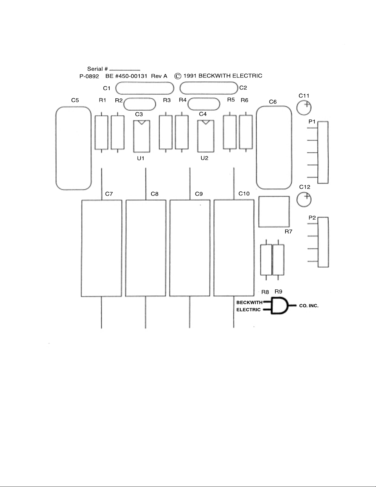
Figure 7 Variable Speed Motor Application Component Location, B-0264
–15–
Page 25
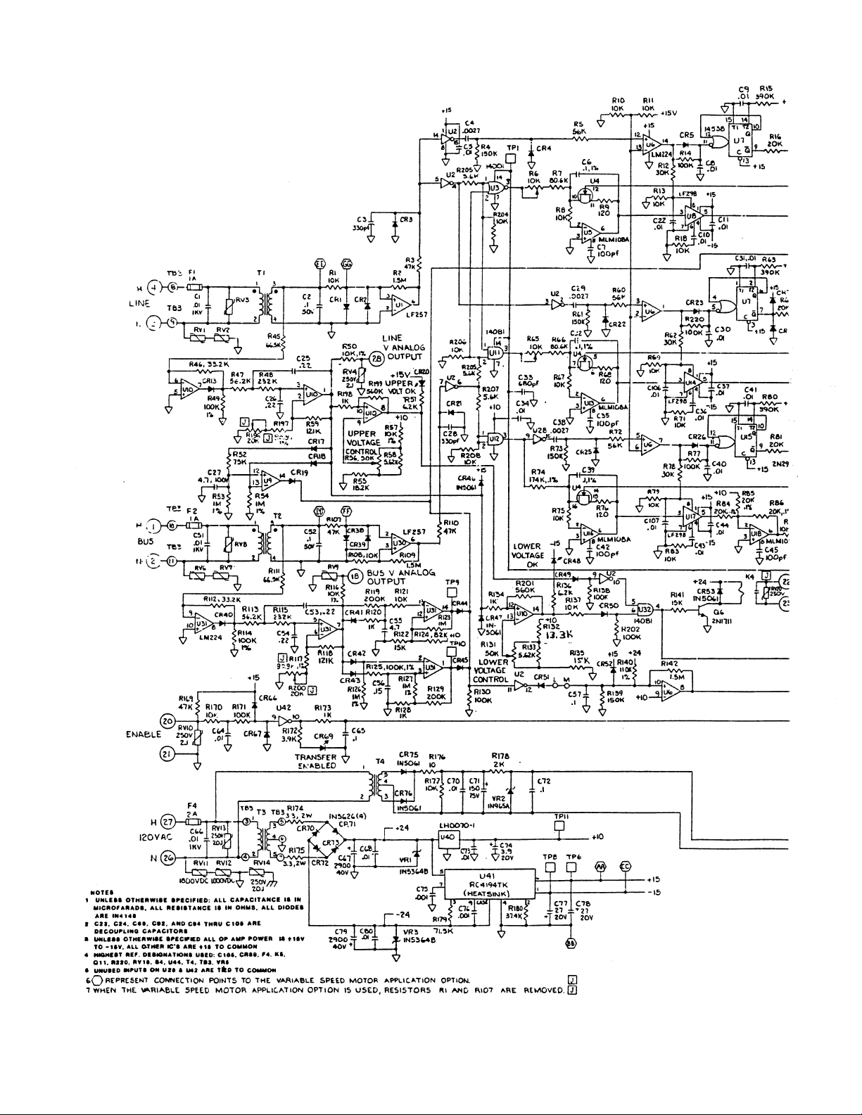
M-0245C Instruction Book
–16–
Page 26
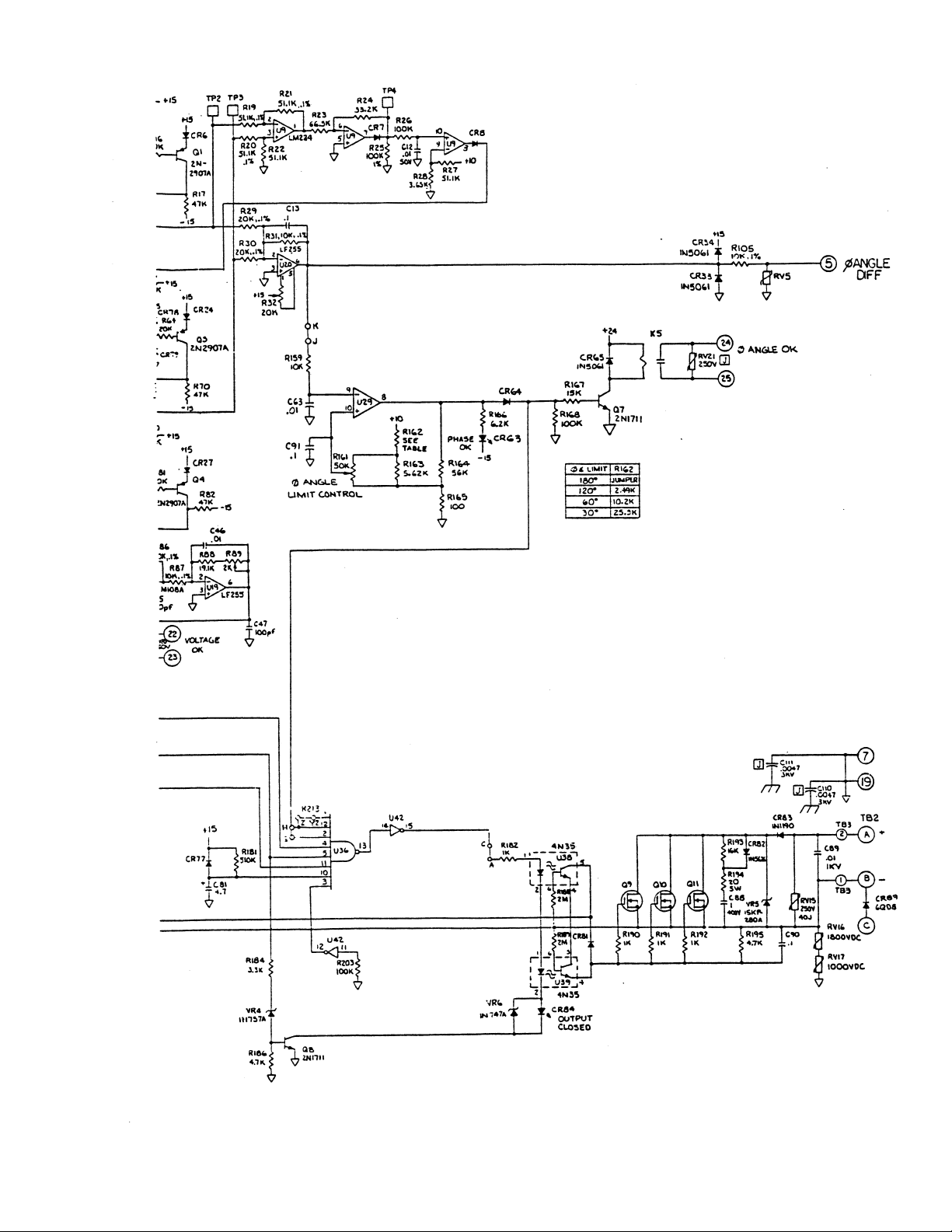
Figure 8 Schematic, X-0245C
–17–
Page 27
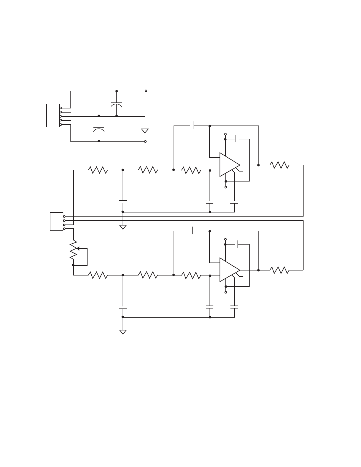
M-0245C Instruction Book
P1
1
2
3
4
5
R1
953
+15
+
C11
2.2
+
C12
2.2
C8
2.0
+15
C1
.01
-15
7
2
R2 R3
953 953
LM208H
-
3
+
U1
6
1
84
R8
10K
1/2W
P2
-15
C5
1.5
4
3
2
1
R7
200
R6
825
R5 R4
953 953
C9
2.0
C7
.47
+15
2
-
3
+
7
U2
C3
100 pf
C2
.01
LM208H
6
1
84
R9
47K
1/2W
-15
C6
1.5
C10
.47
C4
100 pf
Figure 9 Variable Speed Motor Application Schematic, Y-0264
–18–
Page 28
M-0245C Instruction Book
PARTS LIST
M-0245C High Speed Sync-Check Relay
This list includes all electrical and mechanical parts which could conceivably either require replacement
or be lost. The COMPONENT DESIGNATION is the same as that appearing on schematics or referred
to in Instruction Books.
The BECO NUMBER refers to an index maintained by the company. This lists the currently available
device which may be substituted even though the device originally supplied is obsolete and no longer
available. Parts marked by an asterisk* are not available from other sources. Either the original component or a current substitute will be carried in stock by Beckwith Electric.
Parts not marked with an asterisk are normally available from an electronics components house. Those
parts or a current substitute will normally be available from Beckwith Electric stock.
In either case, when parts are ordered from Beckwith Electric, we will be responsible for supplying the
current replacement in the shortest possible time.
Sufficient detailed description is also given to permit purchasing from an electronics parts house,
providing the part is of equal or better quality to insure reliable operation. This may require some interpretation of specifications which may be avoided by direct purchase from Beckwith Electric using the
BECO NUMBER.
Note that in a few instances, components are selected in final test. Procedures described in the TEST
PROCEDURES Section must be followed in replacing these components.
All resistors are 1/2 W unless noted.
COMPONENT
DESIGNATION
C1,C51,C66,C89 000-00904 Capacitor, Ceramic Disc, 0.01 µF ±20%, 1 kV
C2,C52,C91 000-00914 Capacitor, Ceramic Disc, 0.1 µF ±20%, 50 V
C3,C28 010-00613 Capacitor, NPO Ceramic, 330 pF ±10%, 50 V
C4,C29,C38 000-00810 Capacitor, Polyester, 0.0027 µF ±10%, 400 V
C5,C8,C9,C11,C12,C22, 000-00917 Capacitor, Ceramic Disc, 0.01 µF ±20%, 50 V
C24,C30,C31,C34,C37,
C40,C41,C44,C68–C70,
C73,C80,C84,C92,C94–
C99,C101,C103–C107
C6,C32,C39 010-00802 Capacitor, Polysulfone, 0.1 µF ±1%, 50 V
BECO
NUMBER
450-00065* Printed Circuit Board, P-0592
DESCRIPTION
C7,C35,C42,C45,C47 000-00903 Capacitor, Ceramic Disc, 100 pF ±10%, 1 kV
C10,C36,C43 010-00432 Capacitor, Polystyrene, 0.01 µF ±10%, 63 V
–19–
Page 29
M-0245C Instruction Book
COMPONENT
DESIGNATION
C13,C57,C65,C72 000-00811 Capacitor, Polyester, 0.1 µF ±10%, 100 V
C14–C21 Not Used
C23,C90,C100,C102 000-00909 Capacitor, Ceramic Disc, 0.1 µF +80/-20%, 25 V
C25,C26,C53,C54 000-00829 Capacitor, Polyester, 0.22 µF ±10%, 100 V
C27,C55 000-00813 Capacitor, Polyester, 4.7 µF ±10%, 100 V
C33 000-00902 Capacitor, Ceramic Disc, 680 pF ±10%, 1 kV
C46,C63,C64 000-00808 Capacitor, Polyester, 0.01 µF ±10%, 400 V
C48–C50 Not Used
C56 000-00825 Capacitor, Polyester, 0.15 µF ±10%, 100 V
C58–C62 Not Used
C67,C79 000-00637 Capacitor, Electrolytic, 3500 µF +100/-10%, 40 V
C71 000-00652 Capacitor, Electrolytic, 150 µF +75/-10%, 75 V
C74 000-00501 Capacitor, Tantalum, 3.9 µF ±10%, 35 V
C75,C76 000-00913 Capacitor, Ceramic Disc, 0.001 µF, ±10%, 100 V
BECO
NUMBER
DESCRIPTION
C77,C78 000-00504 Capacitor, Tantalum, 27 µF ±10%, 20 V
C81 000-00555 Capacitor, Tantalum, 4.7 µF ±20%, 25 V
C82,C83,C85–C87 Not Used
C88 000-00817 Capacitor, Polyester, 1 µF ±10%, 400 V
C110,C111 000-00939 Capacitor, Ceramic Disc, 0.0047 µF ±20%, 3000 V
CR1–CR8,CR13,CR17– 400-00224 Diode, 1N4148
CR19,CR21–CR27,
CR38–CR45,CR49–
CR52,CR64,CR66,CR67,
CR77–CR79, CR81
CR9–CR12,CR14–CR16 Not Used
CR20,CR48,CR63, 400-00722 Diode, Light Emitting, Hewlett–Packard 5082–4658
CR69,CR84
CR28–CR32 Not Used
CR33,CR34,CR46, 400-00211 Diode, 1N5061
CR47,CR53,CR65,
CR75,CR76
CR35–CR37,CR54– Not Used
CR62,CR68
CR70–CR73,CR82 400-00213 Diode, 1N5626
–20–
Page 30
COMPONENT
DESIGNATION
CR74,CR80 Not Used
CR83 400-00229 Diode, 1N1190
CR89 See PARTS MOUNTED TO THE ENCLOSURE
F1,F2 420-00850 Fuse, 1 A, 125 V, Littelfuse 275–001
F3 Not Used
F4 420-00849 Fuse, 2 A, 125 V, Littelfuse 275–002
K1–K3 Not Used
K4,K5 430-00151 Relay, 24 V dc, SPDT, American Zettler
Q1,Q3,Q4 400-00305 Transistor, PNP, 2N2907A
Q2,Q5 Not Used
Q6–Q8 400-00300 Transistor, NPN, 2N1711
Q9–Q11 400-00422 Transistor, Power FET, Silconix VN45JA
BECO
NUMBER
DESCRIPTION
AZ4UP–E–1C–24D
R8,R10,R11,R13,R18, 200-00103 Resistor, Carbon Film, 10 K ±5%
R67,R69,R71,R75, ■ NOTE: If Variable Speed Motor Application Option is
R79,R83,R108,R121, installed, see that option’s parts list for R1 and R7
R177,R204,R206 values.
R2,R109,R142 200-00155 Resistor, Carbon Film, 1.5 M ±5%
R3,R17,R70,R82, 180-00473 Resistor, Carbon Comp, 47 K ±5%, 1/4 W
R107,R110,R169
R4,R61,R73 200-00154 Resistor, Carbon Film, 150 K ±5%
R5,R60,R72 180-00563 Resistor, Carbon Comp, 56 K ±5%, 1/4 W
R6,R65 360-00093 Potentiometer, 10 K, Bourns 3009P–1–103
R7,R66 330-00588 Resistor, Metal Film, 80.6 K ±1%, 1/4 W, RN60E
NOTE: If Variable Speed Motor Application Option is
installed, see that option’s parts list for R1 and R7
values.
R9,R68,R76 200-00121 Resistor, Carbon Film, 120 Ω ±5%
R12,R62,R78 180-00303 Resistor, Carbon Comp, 30 K ±5%, 1/4 W
R14,R26,R77,R130,R138, 180-00104 Resistor, Carbon Comp, 100 K ±5%, 1/4 W
R168,R171,R202,R203,
R209,R220
R15,R63,R80 200-00394 Resistor, Carbon Film, 390 K ±5%
–21–
Page 31
M-0245C Instruction Book
COMPONENT
DESIGNATION
R16,R64,R81 180-00203 Resistor, Carbon Film, 20 K ±5%, 1/4 W
R19–R22 340-00015 Resistor, Metal Film, 51.1 K ±0.1%, 1/4 W, RN60E5112B
R23,R45,R111 340-00580 Resistor, Metal Film, 66.5 K ±1%, 1/4 W, RN60C
R24,R46,R112 390-00551 Resistor, Metal Film, 33.2 K ±1%, 1/8 W, RN55C
R25,R49,R114,R125 390-00601 Resistor, Metal Film, 100 K ±1%, 1/8 W, RN60C
R27 390-00569 Resistor, Metal Film, 51.1 K ±1%, 1/8 W, RN55C
R28 390-00455 Resistor, Metal Film, 3.65 K ±1%, 1/8 W, RN55C
R29,R30,R84–R86 340-00002 Resistor, Metal Film, 20K ±0.1%, 1/4 W, RN60E
R31,R87 340-00001 Resistor, Metal Film, 10 K ±0.1%, 1/4 W, RN60E
R32 360-00068 Potentiometer, 20 K, Bourns 3009P–1–203
R33–R44 Not Used
R47,R113 390-00573 Resistor, Metal Film, 56.2 K ±1%, 1/8 W, RN55C
R48,R115 390-00636 Resistor, Metal Film, 232 K ±1%, 1/4 W, RN55C
R50,R57,R105,R116 340-00501 Resistor, Metal Film, 10 K ±1%, 1/4 W, RN60C
BECO
NUMBER
DESCRIPTION
R51,R136,R166 200-00622 Resistor, Carbon Film, 6.2 K ±5%
R52 340-00585 Resistor, Metal Film, 75 K ±1%, 1/4 W, RN60C
R53,R54,R126,R127 340-00701 Resistor, Metal Film, 1 M ±1%, 1/4 W, RN60C
R55 330-00526 Resistor, Metal Film, 18.2 K ±1%, 1/4 W, RN60E
R56,R131,R161 360-00119 Potentiometer, 50 K ±10%, Allen Bradley
72B1G040S503W
R58,R133,R163 330-00473 Resistor, Metal Film, 5.62 K ±1%, 1/4 W, RN60E
R59,R118 330-00609 Resistor, Metal Film, 121 K ±1%, 1/4 W
R74 340-00011 Resistor, Metal Film, 174 K ±0.1%, 1/4 W, RN60E
R88 330-00528 Resistor, Metal Film, 19.1 K ±1%, 1/4 W, RN60E
R89 360-00069 Potentiometer, 2 K, Bourns 3009P–1–202
R90–R104,R106 Not Used
R117,R197 390-00593 Resistor, Metal Film, 90.9 K ±1%, 1/8 W, RN55C
R119,R129 200-00204 Resistor, Carbon Film, 200 K ±5%
R120,R128,R134,R182, 200-00102 Resistor, Carbon Film, 1 K ±5%
R190–R192,R198
R122,R141,R167 200-00153 Resistor, Carbon Film, 15 K ±5%
R123 200-00105 Resistor, Carbon Film, 1 M ±5%
R124 200-00823 Resistor, Carbon Film, 82 K ±5%
–22–
Page 32
COMPONENT
DESIGNATION
R132 330-00513 Resistor, Metal Film, 13.3 K ±1%, 1/4 W, RN60E
R135 330-00518 Resistor, Metal Film, 15 K ±1%, 1/4 W, RN60E
R137,R159,R170 180-00103 Resistor, Carbon Comp, 10 K ±5%, 1/4 W
R139 180-00154 Resistor, Carbon Comp, 150 K ±5%, 1/4 W
R140 390-00605 Resistor, Metal Film, 110 K ±1%, 1/8 W
R143–R158,R160 Not Used
R162 Select for 30°, 60°, 120°, or 180° phase angle limit - Refer
R164 200-00563 Resistor, Carbon Film, 56 K ±5%
R165 330-00301 Resistor, Metal Film, 100 Ω ±1%, 1/4 W, RN60E
R172 180-00392 Resistor, Carbon Film, 3.9 K ±5%, 1/4 W
R173 180-00102 Resistor, Carbon Comp 1 K ±5%, 1/4 W
R174,R175 370-00006 Resistor, Wirewound, 3.3 Ω ±5%, 2 W
R176 200-00100 Resistor, Carbon Film, 10 Ω ±5%
BECO
NUMBER
DESCRIPTION
to OPTIONAL COMPONENTS
R178 200-00202 Resistor, Carbon Film, 2 K ±5%
R179, R180 340-00443 Resistor, Metal Film, 2.74 K ±1%, 1/4 W
R181 200-00514 Resistor, Carbon Film, 510 K ±5%
R183 Not Used
R184 200-00332 Resistor, Carbon Film, 3.3 K ±5%
R185 Not Used
R186,R195 200-00472 Resistor, Carbon Film, 4.7 K ±5%
R187 Not Used
R188,R189 200-00205 Resistor, Carbon Film, 2 M ±5%
R193 340-00013 Resistor, Carbon Comp. 16 K ±5%
R194 350-00052 Resistor, Wirewound, 20 Ω ±5%, 5 W
R196,R200 360-00141 Potentiometer, 20 K, ±10%, Bourns 3266W-1-203
R199,R201 180-00564 Resistor, Carbon Comp, 560 K ±5%, 1/4 W
R205,R207,R209 180-00562 Resistor, Carbon Comp, 5.6 K ±5%, 1/4 W
R208 200-00104 Resistor, Carbon Film, 100 K ±5%
R222,R223 390-00339 Resistor, Metal Film, 249K, K1%, 1/8W
R210–R219,R221 Not Used
RV1,RV3,RV6,RV8, 400-00724 Varistor, 250 V, 20 J, G.E. V250LA20
RV13,RV14,RV20,RV21
–23–
Page 33
M-0245C Instruction Book
COMPONENT
DESIGNATION
RV2,RV7,RV11,RV16 400-00718 Varistor, 1800 V dc, 80 J, Panasonic ERZ–C–14DK182
RV4,RV5,RV9,RV10 400-00709 Varistor, 250 V, 2 J, G.E. V250LA2
RV12,RV17 400-00734 Varistor, 1000 V dc, 40 J, Panasonic ERZ–C–14DK102
RV15 400-00727 Varistor, 250 V, 40 J, G.E. V250LA40B
T1,T2 410-00031* Transformer Set, B-0210, U-0086
T3 410-00030* Transformer, U-0085
T4 410-00017* Transformer, U-0029
TB1 420-00052 Terminal Strip, 28–Position, R.D.I. 6PCR-28-001
TB2 See PARTS MOUNTED TO THE ENCLOSURE
TB3 420-00067 Terminal Strip, 11–Position, Curtis GBPC-11
U1,U30 400-00655 Op Amp, National LF257H
U2,U28,U42 400-00638 Hex Inverter, Motorola MC14049BAL
U3 400-00625 Quad 2–Input NOR–Gate, Motorola MC14001BAL
BECO
NUMBER
DESCRIPTION
U4 400-00658 Varafet, Intersil IT401A
U5,U13,U16,U18 400-00633 Op Amp, Motorola MLM108AG
U6,U9,U10,U29,U31 400-00665 Quad Op Amp, National LM224J
U7,U15 540-00010 Multivibrator, Motorola MC14538BAL
U8,U14,U17 400-00656 Sample and Hold, National LF298H
U11,U12,U32 400-00636 Quad 2–Input AND–Gate, Motorola MC14081BAL
U19,U20 400-00620 Op Amp, National LF255H
U21–U27,U33–U35 Not Used
U36 400-00683 8–Input NAND–Gate, Motorola MC14068BAL
U37 Not Used
U38,U39 400-00716 Photon Coupled Isolator, G.E. 4N35
U40 400-00644 Voltage Reference, National LH0070-1H
U41 560-00010 Voltage Regulator, Raytheon RC4194TK
VR1,VR3 400-00057 Diode, Zener, 33 V ±5%, 5 W, 1N5364B
VR2 400-00030 Diode, Zener, 15 V ±10%, 400 mW, 1N965B
VR4 400-00056 Diode, Zener, 9.1 V ±5%, 400 mW, 1N757A
VR5 400-00074 Transient Suppressor, General Semiconductor Ind.
15KP280A
VR6 400-00017 Diode, Zener, 3.6 V ±5%, 400 mW, 1N747A
–24–
Page 34
COMPONENT
DESIGNATION
BECO
NUMBER
DESCRIPTION
PHASE ANGLE LIMIT CONTROL OPTION
R162 370-00020 Jumper = 180
190-00439 Resistor, Metal Film, 2.49 K ±1%, 1/8 W = 120
190-00502 Resistor, Metal Film, 10.2 K ±1%, 1/8 W = 60
190-00540 Resistor, Metal Film, 25.5 K ±1%, 1/8 W = 30
0
0
0
0
PARTS MOUNTED TO THE ENCLOSURE
CR89 400-00230 Diode, 6QD8
TB2 420-00051 Terminal Block, Barrier Strip, Cinch-Jones 8-142Y
50 HZ OPTION
B-0207-D1
R7, R66 330-00601 Resistor, 100KΩ, K1%, 1/4W
R74 330-00632 Resistor, 210KΩ, K1%, 1/4W
–25–
Page 35
M-0245C Instruction Book
COMPONENT
DESIGNATION
BECO
NUMBER
DESCRIPTION
B-0264 VARIABLE SPEED MOTOR APPLICATION
C1,C2 000-00904 Capacitor, 0.01 µF, ±20%, 1KV, Centralab DD-1032
C3,C4 000-00903 Capacitor, 100 pf, ±20%, 1KV, Centralab DD-101
C5,C6 010-00549 Capacitor, 1.5 µF, 100 V, Polyester Seacor MMKK
C7,C10 010-00441 Capacitor, 0.47 µF, ±1%, 50V, Polystyrene,
F-dyne PC12.47-50-1
C8,C9 010-00800 Capacitor, 2.0 µF, ±5%, 50V Component Research
H14B205DXW
C11,C12 000-00553 Capacitor, 2.2 µF, 25V, Tantalum Panasonic F25E2R2
R1-R5 340-00395 Resistor, Metal Film, 953 Ω, ±1%. 1/4 W RN60C
R6 330-00389 Resistor, Metal Film, 825 Ω, ±1%. 1/4 W RN60E
R7 360-00034 Potentiometer, 200ý, ±20%. Bourns 3386P-1-201
R8 200-00103 Resistor, Carbon Film, 10KΩ, ±5%
R9 200-00473 Resistor, Carbon Film, 47KΩ, ±5%
U1,U2 560-00011 OP AMP, LM108AJ-8
–26–
Page 36

Legal Information
Patent
The units described in this manual are covered by
U.S. Patents 4,218,625 and 4,256,972.
Buyer shall hold harmless and indemnify the Seller,
its directors, officers, agents, and employees from
any and all costs and expense, damage or loss,
resulting from any alleged infringementof United
States Letters Patent or rights accruing thereform or
trademarks, whether federal, state, or common law,
arising from the Seller’s compliance with Buyer’s
designs, specifications, or instructions.
Warranty
Seller hereby warrants that the goods which are the
subject matter of this contract will be manufactured
in a good workmanlike manner and all materials
used herein will be new and reasonably suitable for
the equipment. Seller warrants that if, during a
period of two years from date of shipment of the
equipment, the equipment rendered shall be found
by the Buyer to be faulty or shall fail to peform in
accordance with Seller’s specifications of the
product, Seller shall at his expense correct the
same, provided, however, that Buyers shall ship the
equipment prepaid to Seller’s facility. The Seller’s
responsibility hereunder shall be limited to replacement value of the equipment furnished under this
contract.
Seller makes no warranties expressed or implied
other than those set out above. Seller specifically
excludes the implied warranties of merchantibility
and fitness for a particular purpose. There are no
warranties which extend beyond the description
contained herein. In no event shall Seller be liable for
consequential, exemplary, or punitive damages of
whatever nature.
Any equipment returned for repair must be sent
with transportation charges prepaid. The equipment
must remain the property of the Buyer. The aforementioned warranties are void if the value of the
unit is invoiced to the Seller at the time of return.
Indemnification
The Seller shall not be liable for any property
damages whatsoever or for any loss or damage
arising out of, connected with, or resulting from
this contract, or from the performance or breach
thereof, or from all services covered by or furnished
under this contract.
In no event shall the Seller be liable for special,
incidental, exemplary, or consequential damages,
including but not limited to, loss of profits or
revenue, loss of use of the equipment or any
associated equipment, cost of capital, cost of
purchased power, cost of substitute equipment,
facilities or services, downtime costs, or claims or
damages of customers or employees of the Buyer
for such damages, regardless of whether said claim
or damages is based on contract, warranty, tort
including negligence, or otherwise.
Under no circumstances shall the Seller be liable
for any personal injury whatsoever.
It is agreed that when the equipment furnished
hereunder are to be used or performed in connection with any nuclear installation, facility, or
activity, Seller shall have no liability for any
nuclear damage, personal injury, property damage,
or nuclear contamination to any property located at
or near the site of the nuclear facility. Buyer agrees
to indemnify and hold harmless the Seller against
any and all liability associated therewith whatsoever whether based on contract, tort, or otherwise.
Nuclear installation or facility means any nuclear
reactor and includes the site on which any of the
foregoing is located, all operations conducted on
such site, and all premises used for such operations.
Notice:
Any illustrations and descriptions by Beckwith
Electric Co., Inc. are for the sole purpose of
identification.
The drawings and/or specifications enclosed herein
are the proprietary property of Beckwith Electric
Co., Inc., and are issued in strict confidence;
therefore, shall not be used as a basis of reproduction of the apparatus described therein without
written permission of Beckwith Electric Co., Inc.
No illustration or description contained herein
shall be construed as an express warranty of
affirmation, promise, description, or sample, and
any and all such express warranties are specifically
excluded nor shall such illustration or description
imply a warranty that the product is merchantable
or fit for a particular purpose. There shall be no
warranties which extend beyond those contained in
the Beckwith Electric Co., Inc. terms of sale.
All rights reserved by Beckwith Electric Co., Inc. No reproduction may be made without prior written approval
of the Company.
Page 37

This Page Left Intentionally Blank
Page 38

BECKWITH ELECTRIC CO., INC.
6190 - 118th Avenue North • Largo, Florida 33773-3724 U.S.A.
PHONE (727) 544-2326 • FAX (727) 546-0121
E-MAIL [email protected]
WEB PAGE www.beckwithelectric.com
© Beckwith Electric Co.
Printed in USA 800-0245C-IB-00 04/01
 Loading...