

Page 1
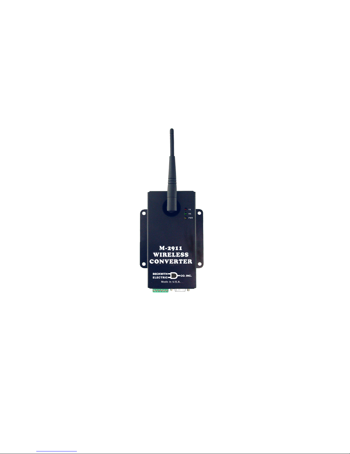
BlueJay™ Universal
Data Transceiver
M-2911
CONTROLS
• Provides direct sequence spread spectrum peer-to-peer, point-topoint, point-to-multipoint and master/slave high speed (1 Mbps) data
transmission rates at ranges up to 1500 feet
• Interfaces using either a RS-232, RS-422 or RS-485 connection at
interface baud rates between 2400 and 115.2 Kbps
• Substation hardened to withstand temperatures from -40 to +80
degrees C and humidity up to 95%
• No user license required, interfaces with almost any legacy IED
Page 2
Page 3

M-2911 BlueJay Universal Data Transceiver
The M-2911 Blue Jay™ Universal Data Transceiver is a self-contained short-range wireless communication
device (SRD) that is used for transferring serial communication data between Intelligent Electrical Device's
(IED’s) and computers hosting control software in an industrial environment. The M-2911 is based on an
Intersil direct sequence spread spectrum chip set that operates in the 2.4 GHz ISM band. The M-2911 design
meets the category for low power devices (LPDs) standard requirement for license-free operation.
Interface
The M-2911 is equipped with two serial data connectors, one is a DE-9 connector for use with an RS-232
serial data port and the other is a 6-pin bare wire Phoenix–type connector for use with an RS-422/RS-485
(twisted shielded pair) serial data ports. Only one port can be used at a time. Each port is capable of serial
data speeds of up to 115 kbps.
Data Transmission:
-5
• Error Detection – 16 bit CRC (10
BER at –70dBm)
• Maximum throughput – 1 Mbps RF, 2400 to 115.2 Kbps interface baud rate
Communication
The M-2911 conditions the data and transmits it over a half-duplex direct sequence spread spectrum radio
operating in the 2.4 GHz ISM band. The over-the-air data rate is 1 Mbps.
Transmit:
• Frequency Range – 2400 MHz to 2483.5 MHz
• Output Power – 30 mW
• Modulation – DBPSK
• Occupied Bandwidth – 20 MHz
• Spurious Emissions – 50 mV/meter
• Harmonic Emissions – 500 uV/meter
• Spreading Method – Direct Sequence 11 bit code
• Center Band – Carrier 2.450 GHz
Receive:
• Sensitivity – -93 dBm
• Selectivity – 25 MHz
■ NOTE: For maximum range, all antennae must be oriented in the same plane.
Power
The M-2911 includes a self-contained switching power supply that supplies the data and RF circuitry with
regulated dc power as required. The power supply has an external 3.5 mm outside diameter, 2.1 mm inside
pin, center positive power input jack designed to accept the output of a UL listed wall transformer power
supply included with each unit that delivers between 7 and 60 V dc at a maximum power output of 2.5 Watts.
Power Requirements:
• Operating Voltage – +7 to +60 V dc
• Transmit Current – 2 W (300 mA @ 7 V)
• Receive Current – 2 W (300 mA @ 7 V)
• Inlet Current – 1 W (150 mA @ 7 V)
• Sleep Current – 0.2 W (30 mA @ 7 V)
–3–
Page 4

M-2911 BlueJay Universal Data Transceiver
Configuration
The M-2911 is configurable with the following parameters:
• Unit (Transmit/Receive) Address: 1 to 250
• Destination (Transmit): 1 to 255
• Multicast (Receive) Address: 251 to 254
• Baud Rate: Selectable from 2400 to 115,200
• Parity: Even/Odd/No Parity
• Transmit Retry: 0 to 9 times
• Interface: RS-232/RS-422/RS-485
• RS-232 RTS/CTS: FIXED/AUTO/FLOW-THRU
• RS-422/485 Tx:
Gating: 0 to 10 characters
Lead Time: 0 to 10 mS
Hold Time: 0 to 10 mS
• Intercharacter Timeout: 1 to 10 character times/1 to 100 mS
• Maximum Packet Size: 1 to 60 characters
Configuring the M-2911
To configure the M-2911, the unit must be put in the AT-Command Mode. To put the unit in AT-Command
Mode:
1. Connect the unit (using an RS-232 cable) to a PC or laptop computer running a terminal emulator
program (such as Microsoft HyperTerminal) set to 9600 bps, No Parity, One Stop Bit.
2. Apply power to the unit.
3. After 1–2 seconds, type "+++", and pause for 1 second or more. The M-2911 will enter
AT-Command Mode and respond with "OK". The user can then enter any of the AT Commands
listed below.
■ NOTE: After each command, the unit will return "OK" if the command was valid, or "???" if invalid or out-
of-range.
AT Commands
Unit (Transmit/Receive) Address Configuration: ATS=nnn<ENTER>, where nnn is 1 to 250
Destination (Transmit) Address Configuration: ATD=nnn<ENTER>, where nnn is 1 to 255
Multicast (Receive) Address Configuration: ATM=nnn<ENTER>, where nnn is 251 to 254
Baud Rate Select: ATB=nnnnnn<ENTER>, where nnnnnn is 2400, 4800, 9600, 19200, 38400, 76800, or
115200
Parity Select: ATP=x, where x is E for Even Parity, O for Odd Parity, or N for No Parity
Transmit Retries Configuration: ATR=n<ENTER>, where nn is 0 to 9
Interface Selection: RS-232, RS-422, or RS-485
ATI=RS232<ENTER>
ATI=RS422<ENTER>
ATI=RS485<ENTER>
RS-232 RST Configuration:
ATI=RTSx<ENTER>, where x is 0 for Low, 1 for High, F for Flow-Thru
ATI=CTSx<ENTER>, where x is 0 for Ignore, 1 for Obey, F for Flow-Thru
–4–
Page 5

M-2911 BlueJay Universal Data Transceiver
RS-422 Tx Gating Configuration:
ATI=TXO<ENTER>, to set Transmit On.
ATI=TXLnC<ENTER>, to set Transmit On Lead Time to n characters
ATI=TXHnC<ENTER>, to set Transmit On Hold Time to n characters
ATI=TXLnnn<ENTER>, to set Transmit On Lead Time to nnn mS
ATI=TXHnnn<ENTER>, to set Transmit On Hold Time to nnn mS
Intercharacter Timeout Configuration:
ATT=nnC<ENTER>, where nn is1–10
ATT=nnn<ENTER>, where nnn is 1–1,000 for 1 mS to 1000 mS
Maximum Packet Size Configuration: ATN=nn<ENTER>, where nn is 1–52
View Settings: ATV<ENTER>; the command returns the following (example) parameters:
Beckwith Electric M-2911 BlueJay Transceiver
Software Version 01.00
Serial Number: 001.032
Unit Address: 001, Destination Address: 002, Multicast Address: 251
Baud Rate: 9600 bps, No Parity
Transmit Retry: 5
RS-232, RTS Flow-Thru, DTR Flow-Thru, DSR Flow-Thru
Intercharacter Timeout: 5 Char, Maximum Packet Size: 32 Char
Exit AT-Command Mode: ATZ
Application Information
BBXRataDevieceR2niP
ABXTataDtimsnarT3niP
ACSTRdneSottseuqeR7niP
BCSTCdneSotraelC
DCRTDydaeRlanimreTataD4niP
FCDCDtceteDreirraCataD
BADNGdnuorGlangiS5niP
Table 1 RS-232 Communication Port Signals
tiucriC langiS
S9-BD
232-SR
–5–
Page 6
M-2911 BlueJay Universal Data Transceiver
RS-232 Communication
M-2911
DB9S
1
RX
TX
2
3
4
SGND
5
6
RTS
CTS
7
8
9
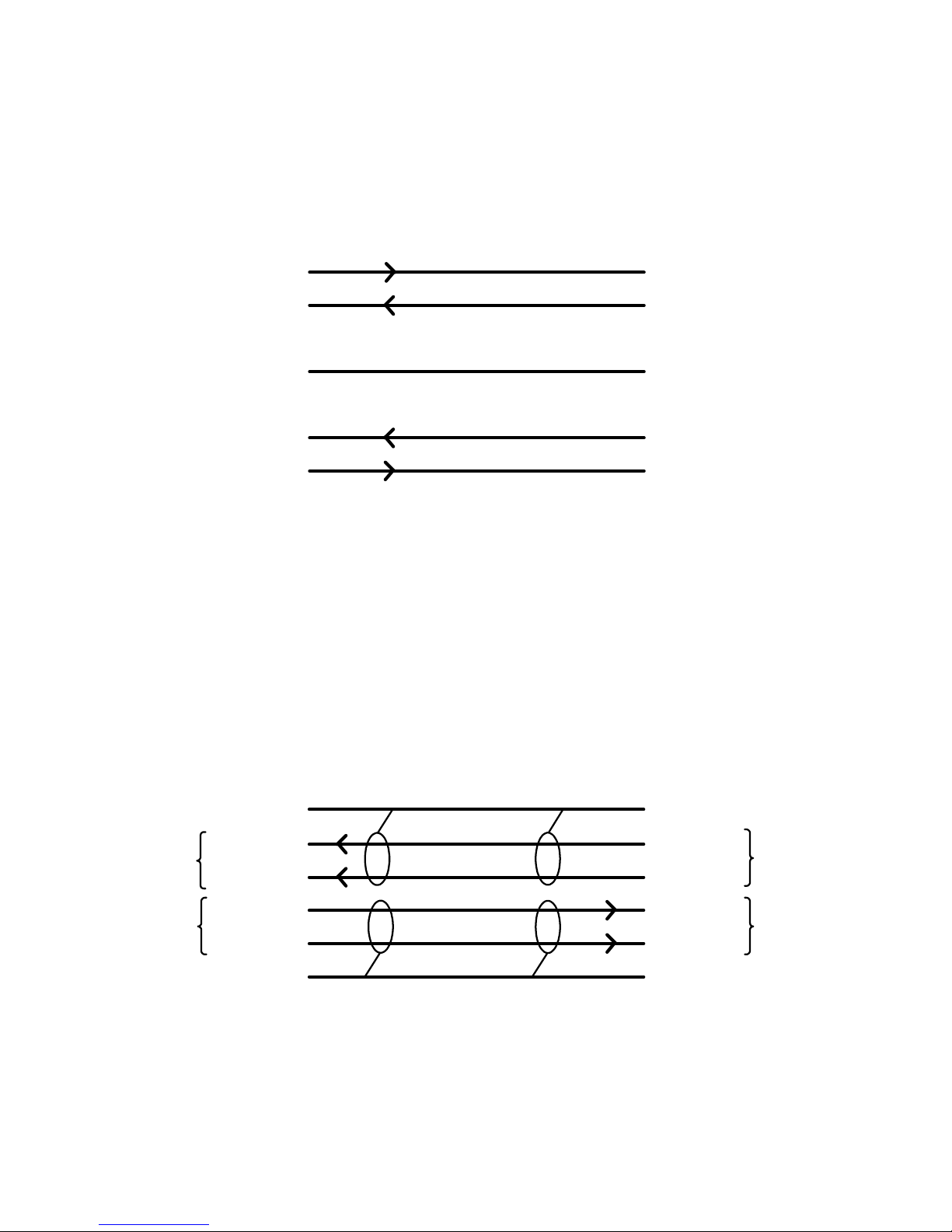
Figure 1 RS-232 Pin-out
RS-232 is point-to-point (four wires plus shield) from M-2911 to one IED.
PC
DB9P
1
2
3
4
5
6
7
8
9
RX
TX
SGND
RTS
CTS
RS-422 Communication
M-2911
6 Pin Terminal
Block P1
SGND
D-
RX
D+
D-
TX
D+
SGND
1
2
3
4
5
6
Shielded Twisted Pair
Figure 2 RS-422 Pin-out
RS-422
Connection
1
SGND
2
D-
3
D+
4
D-
5
D+
6
SGND
TX
RX
–6–
Page 7
M-2911 BlueJay Universal Data Transceiver
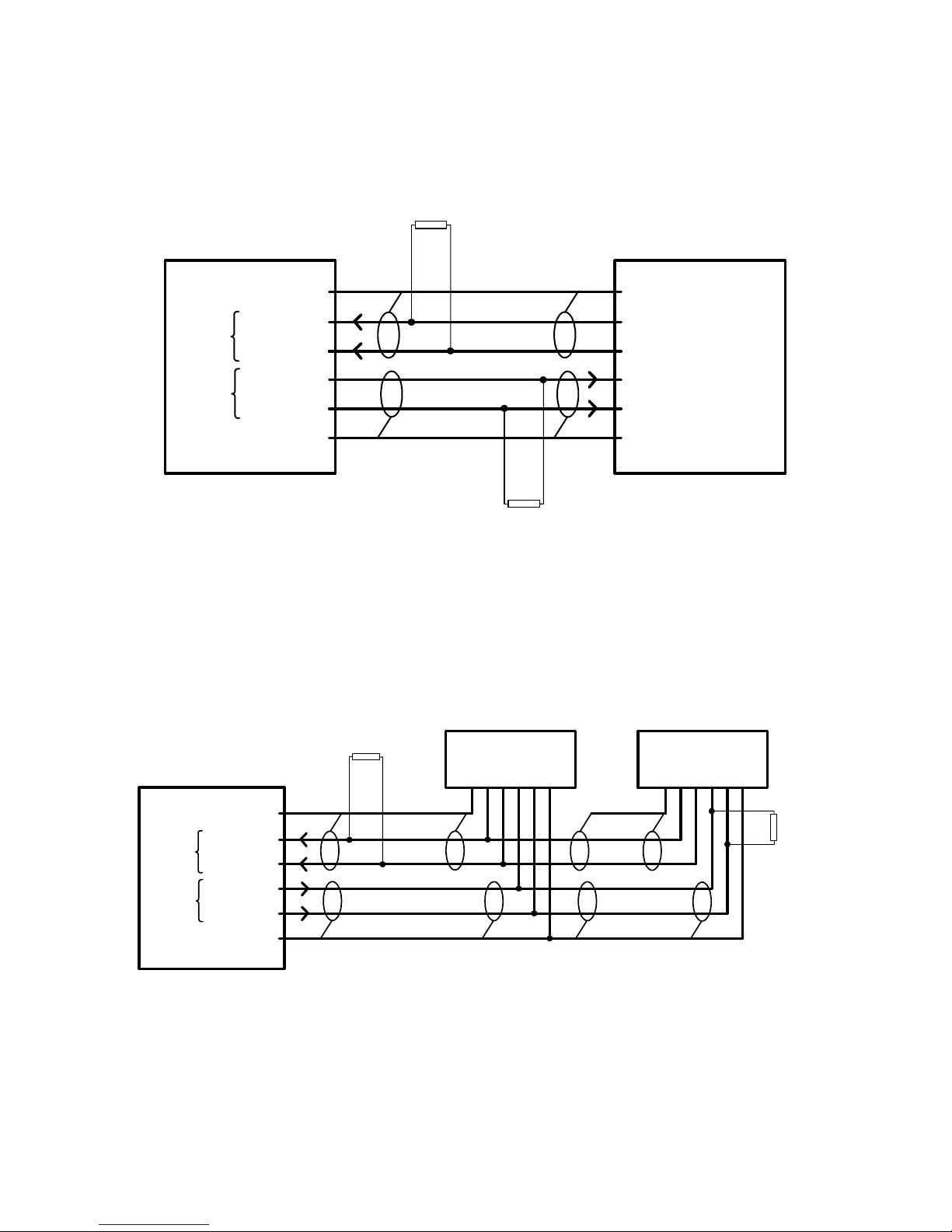
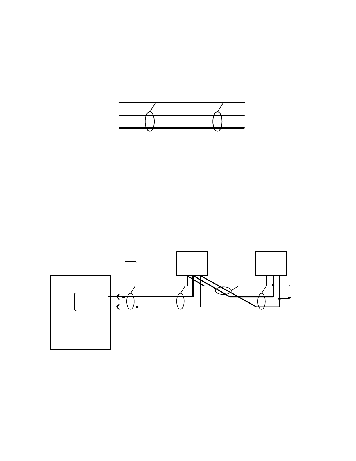
RS-422 is a dual shielded, twisted pair (four wires plus two shields), from M-2911 to one IED.
M-2911
200
RS-422
SGND
RX
DD+
TX
DD+
SGND
RS-422 network is a dual shielded twisted pair (four wires plus two shields), from M-2911 to IEDs in parallel.
1
2
3
4
5
6
IED
200
Figure 3 RS-422 Example IED
M-2911
RS-422
SGND
D-
RX
D+
D-
TX
D+
SGND
IED's In Parallel
200
1
2
3
4
5
6
Figure 4 RS-422 Network Example IED's in Parallel
IEDIED
200
–7–
Page 8
M-2911 BlueJay Universal Data Transceiver
RS-485 Communication
M-2911
6 Pin Terminal
Block P1
SGND
D-
D+
N/C
N/C
N/C
RS-485 is a single shielded twisted pair (two wires plus shield), from M-2911 to IEDs in parallel.
1
2
3
4
5
6
Figure 5 RS-485 Pin-out
IED's In Parallel
RS-485
Network
1
SGND
2
D-
3
D+
4
5
6
M-2911
RS-485
RX/TX
SGND
D-
D+
N/C
N/C
N/C
200
1
2
3
4
5
6
Figure 6 RS-485 Example IED's in Parallel
IEDIED
200
–8–
Page 9
M-2911 BlueJay Universal Data Transceiver
.25
3.88
3.38
TX
RX
PWR
4.51
1.00
1.50
3.62 (2X)
5.50
3.08
1.15
.56
M-2911
WIRELESS
CONVERTER
BECKWITH
ELECTRIC
Made in U.S.A.
CO. INC.
2.75
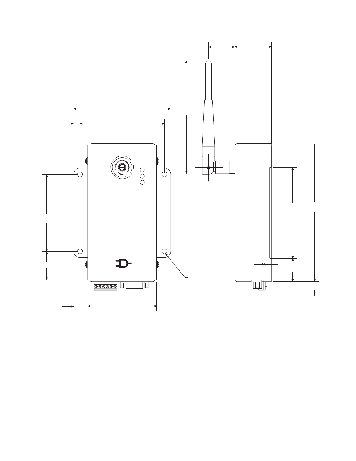
Figure 7 Outline Dimensions
.20 DIA
(4X)
.93 (2X)
.38
–9–
Page 10
M-2911 BlueJay Universal Data Transceiver
Environmental
Temperature: Proper operation maintained from –40°C to +80°C.
Storage Temperature: –50°C to +100°C.
Humidity: Proper operation is maintained up to 95% relative humidity (non-condensing).
Environmental Protection: The power supply printed circuit board is conformally coated to inhibit fungus
growth.
Enclosure: 1/16" Aluminum.
Physical
Size: 5.88" high (with antenna 9.43") x 3.88" wide x 2.5" deep (14.58 cm (23.1) x 9.9 cm x 6.13 cm). See
Figure 7 for dimensional drawing.
Weight: 2.13 oz (60 grams)
Enclosure meets requirements of IP30.
Safety and Cautions
8 WARNING: The installation, maintenance, and/or operation of this equipment could present
potentially unsafe conditions, including, but not limited to, electrical shock or improper voltage to
components. Improper operation could cause personal injury, death, or damage to property.
Read all safety instructions before operating the M-2911, and retain them for further reference. Follow all
operating and usage instructions, and make special note of the following safety symbols:
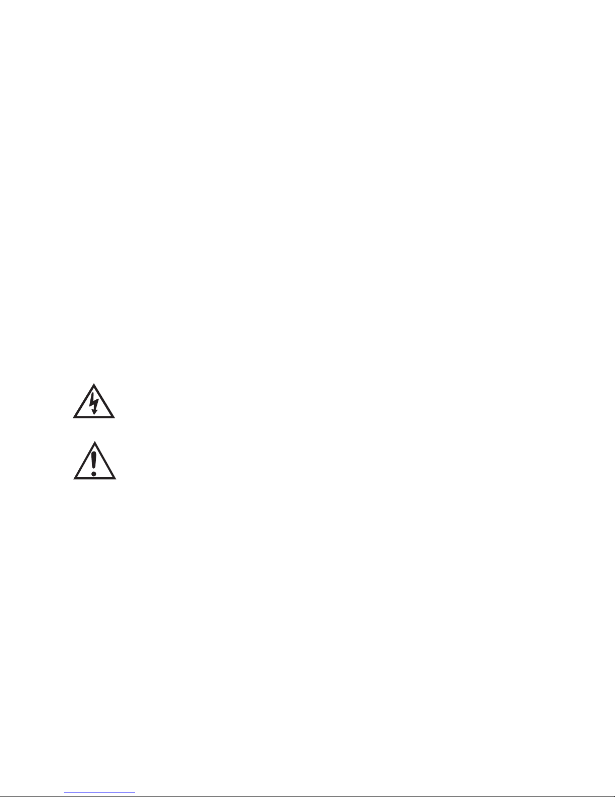
– This sign warns that the area is connected to a dangerous high voltage, and you must
never touch it.
– This sign means that you should refer to the corresponding section of the operation
manual for important information before proceeding.
Do not attempt to perform maintenance or service functions that are not described in the operating
instructions. Instead, refer all such service requirements to Beckwith Electric Co., Inc. Unit must be returned
for service in secure (preferably original) packaging. Shipping cost must be paid by user.
Only the antenna provided is authorized for use with the M-2911. If the antenna is lost or damaged, please
contact Beckwith Electric Co., Inc. to secure a replacement antenna.
This product generates, uses, and can radiate radio frequency (RF). If it is not installed and used in
accordance with the operating instructions, it can cause harmful interference to communications. If this
equipment causes harmful interference to radio or television reception, the user should try and correct the
interference by:
• Reorienting or relocating the receiving/transmitting antenna
• Increasing the separation between the equipment and the M-2911
• Connecting the equipment into an outlet on a different circuit from the M-2911.
If these do not correct the interference, consult an experienced radio/television technician for assistance.
Correcting such interference is the responsibility of the user, not the manufacturer.
–10–
Page 11

M-2911 BlueJay Universal Data Transceiver
Compliance
This device has been designed to operate with an antenna having a maximum gain of 2 dB. Antenna having
a higher gain are strictly prohibited per regulations of Industry Canada. The required antenna impedance is 50
ohms.
This equipment has been tested and found to comply with the limites for a Class A digital device, pursuant to
Part 15.247 and 15.109 of the FCC Rules and Industry Canada RSS-210 and ICES-003. These limits are
designed to provide reasonable protection against harmful interference when the equipment is operated in a
commercial environment. This equipment generates, uses, and can radiate radio frequency energy, and, if
not installed and used in accordance with the instruction manual, may cause harmful interference to radio
communications. Operation of this equipment in a residential area is likely to cause harmful interference in
which case the user will be required to correct the interference at his own expense.
Patent & Warranty
■ NOTE: Changes or modifications to the unit not expressly approved by Beckwith Electric Co. may void
the user's authority to operate the equipment.
U.S. Patent for the M-2911 BlueJay™ Universal Data Transceiver is pending.
The M-2911 BlueJay™ Universal Data Transceiver is covered by a five year warranty from the date of
shipment.
Specification is subject to change without notice.
–11–
Page 12

4
9
9
1
:
1
0
0
9
R
i
g
e
O
S
I
d
e
r
e
t
s
BECKWITH ELECTRIC CO., INC.
6190 - 118th Avenue North • Largo, Florida 33773-3724 U.S.A.
PHONE (727) 544-2326 • FAX (727) 546-0121
E-MAIL [email protected]
WEB PAGE www.beckwithelectric.com
© 2002 Beckwith Electric
Printed in U.S.A. (08.30.02)
800-2911-SP-00MC1 11/02
 Loading...