

Beckhoff CP7103, CP7111, CP7110, CP7112, CP7113 Installation And Operating Instructions Manual
...Page 1

Installation and Operating instructions for
Panel-PC CP71xx
Version: 1.2
Date: 2006-03-06
Page 2

Page 3

Table of contents
Table of contents
1.
General Notes 3
Notes on the documentation 3
Liability conditions 3
Description of safety symbols 3
Basic safety measures 4
Operator's obligation to exercise diligence 5
Operator requirements 5
2.
Product Description 6
Appropriate Use 6
Structure 6
Access to the drives 7
Interfaces 8
USB interfaces 8
Network connection 8
Serial interface 8
DVI-I interface (in use) 8
USB interface (in use) 8
Serial interface (in use) 8
Additional plug-in cards (optional) 8
3.
Installation Instructions 9
Transport and Unpacking 9
Transport 9
Unpacking 9
Installation of the PC 10
Earthing measures 10
Power Supply Connection 11
Electrical data 11
Pin assignment of the connector 11
Fitting the cable 12
Assembling the connector 12
Connecting Power Supply 13
Cable Cross Sections 13
PC_ON, Power-Status 13
Wiring diagram 13
Connecting devices 14
Connecting cables 14
Check voltage rating and connect 14
4.
Operating Instructions 15
Switching the Industrial PC on and off 15
First switching on and driver installation 15
UPS Software Components (optional) 16
Installation on the PC 16
Help files 16
Maintenance 17
Cleaning the Industrial PC 17
Replacing the battery on the motherboard 17
Servicing 17
Shutting down 17
Disposal 17
5.
Troubleshooting 18
Fault correction 18
Service support 19
Beckhoff Service 19
Beckhoff Support 19
Company headquarters 19
CP71xx 1
Page 4

Table of contents
6.
Assembly dimensions 20
7.
Appendix 21
Technical data 21
Approvals 21
FCC: Federal Communications Commission Radio Frequency Interference
Statement 21
FCC: Canadian Notice 21
2 CP71xx
Page 5
General Notes
General Notes
Notes on the documentation
This description is only intended for the use of trained specialists in control
and automation engineering who are familiar with the applicable national
standards. It is essential that the following notes and explanations are
followed when installing and commissioning these components.
Liability conditions
The responsible staff must ensure that the application or use of the
products described satisfy all the requirements for safety, including all the
relevant laws, regulations, guidelines and standards.
The documentation has been prepared with care. The products described
are, however, constantly under development. For this reason, the
documentation may not always be have been fully checked for consistency
with the performance data, standards or other characteristics described.
None of the statements in this manual represent a guarantee for as set out
in § 443 of the German Civil Code or a statement about the assumed use
according to the contract as set out in § 434 para. 1 clause 1 no. 1 of the
German Civil Code. In the event that it contains technical or editorial errors,
we retain the right to make alterations at any time and without warning. No
claims for the modification of products that have already been supplied
may be made on the basis of the data, diagrams and descriptions in this
documentation.
© This documentation is protected by copyright. Any reproduction or third
party use of this publication, whether in whole or in part, without the written
permission of Beckhoff Automation GmbH, is forbidden.
Description of safety symbols
i
Danger
Warning
Note
The following safety symbols are used in this operating manual. They are
intended to alert the reader to the associated safety instructions.
This symbol is intended to highlight risks for the life or health of personnel.
This symbol is intended to highlight risks for equipment, materials or the
environment.
This symbol indicates information that contributes to better understanding.
CP71xx 3
Page 6

General Notes
Basic safety measures
Only switch the PC off after
closing the software
Warning
Before the Industrial PC is switched off, software that is running must
be properly closed.
Otherwise it is possible that data on the hard disk is lost. Please read the
section on Switching the Industrial PC on and off.
Switch off all parts of the equipment, then uncouple the fieldbus!
Before opening the housing of the PC, and whenever the PC is being used
for purposes other than plant control, such as during functional tests
following repair, all parts of the equipment must first be switched off, after
which the Industrial PC can be uncoupled from the plant.
Pulling out the fieldbus connection plug uncouples the PC (optional).
Items of equipment that have been switched off must be secured against
being switched on again.
The Industrial PC’s power supply unit must be supplied with 24 VDC.
Do not exchange any parts when under power!
When components are being fitted or removed, the supply voltage must be
switched off.
Fitting work on the Industrial PC can result in damage:
• If metal objects such as screws or tools fall onto operating circuit
boards.
• If connecting cables internal to the PC are removed or inserted
during operation.
• If plug-in cards are removed or inserted when the PC is switched
on.
4 CP71xx
Page 7

General Notes
Operator's obligation to exercise diligence
National regulations
depending on the machine
type
Warning
Procedure in the event of a
fault
The operator must ensure that
• the Industrial PC is only used for its intended use (see also
Product Description chapter).
• the Industrial PC is in a sound condition and in working order
during operation.
• the operation manual is in good condition and complete, and
always available for reference at the location of the Industrial PC.
• the Industrial PC is operated, maintained and repaired only by
sufficiently qualified and authorized personnel.
• the personnel is instructed regularly about relevant occupational
safety and environmental protection aspects, and is familiar with
the operating manual and in particular the safety notes contained
herein.
• none of the safety and warning notes attached to the Industrial PC
are removed, and that all notes remain legible.
Depending on the type of machine and plant in which the Industrial PC is
being used, there will be national regulations for the control of such
machines and plant that the operator must observe. These regulations
cover, amongst other things, the intervals between inspections of the
controller.
The operator must initiate such inspections in good time.
Only trained persons may open the Industrial PC housing!
The operator is responsible for ensuring that only trained electrical staff
opens the housing of the Industrial PC.
In the event of a fault in the Industrial PC, appropriate measures can be
determined with the aid of the list in the Fault correction section.
Operator requirements
Read the operating
instructions
Software knowledge
Every user of the Industrial PC must have read these operating
instructions.
Every user must be familiar with any of the functions of the software
installed on the PC that he can reach.
CP71xx 5
Page 8

Product Description
Product Description
Rear view of the CP71xx
Appropriate Use
The water protected Panel-PC CP71xx with plug-in card motherboard is
designed for mounted behind a Beckhoff Control Panel.
Structure
1
2
1
Opening the housing
i
Note
Internal view of the PC
In order to open the PC housing, first remove the two M4 screws (1) using
a combination wrench SW 7 and the Allen screw (2) using a No.2 Allen key
(see photo above). The cover of the housing can then be removed to the
rear.
The position of the screws varies according to the position of the mounting
arm.
3
2
1
6 CP71xx
Removing the outer housing provides access to the inner chassis (1), the
power supply unit (2) and the interfaces (3) of the PC. The inner chassis is
fastened with 4 crosshead screws (see arrows).
Page 9

Product Description
b
Rapid access to integrated
components
Side view of the
Panel PC
4
3
a
5
6
1
2
After removing the fastening screws the inner chassis can be taken off,
thus providing access to the processor with cooling ribs and fan (1),
memory (2), plug-in cards (3), floppy disk drive (4), CD-ROM drive (5)
(optional) and Status-LEDs (6).
After unscrewing the crosshead screw (a) and removing the sheet metal
cover you can pull out the CD-ROM drive.
Unscrewing the crosshead-screw (b) and removing the card holder allows
access to the free slot.
Access to the drives
1
2
3
5
4
Opening the side door
Unlock the side door (1) through tricks of the button (2) and then push the
door to the side.
After opening the side door you have access to the floppy disk drive (3),
the CD-ROM drive (4) (optional) and the Status-LEDs with Reset
button (5).
CP71xx 7
Page 10

Product Description
Interfaces to the add-on
Panel PC CP71xx
Interfaces
USB1, USB2
Network
RS 232
COM1
DVI
USB3
RS 232
COM2
Type plate
1
3
4
2
5
7
6
USB interfaces
The two USB interfaces (1) and (2) are used for connecting peripheral
devices with USB port. USB 2.0 standard is supported.
Network connection
Two 10/100 Base-T RJ-45 connectors (3) allow the PC to be connected to
a Local Area Network (LAN).
Serial interface
The Industrial PC CP71xx has one available serial RS232 interface
COM1 (4) which is connected to a 9-pin SUB-D pin connector.
DVI-I interface (in use)
The DVI-I interface (5) is used for connecting the Control Panel.
USB interface (in use)
An additional USB-interface (6) is used for connecting the Control Panel.
Serial interface (in use)
The serial interface COM2 (7), using the type RS232, is used for
connecting the power supply unit.
Additional plug-in cards (optional)
There is a type plate at the housing of the Industrial PC which provides
information about the hardware configuration of the Industrial PC at the
time it was supplied.
8 CP71xx
Page 11
Installation Instructions
Installation Instructions
Warning
Please also refer to chapter General Notes.
Transport and Unpacking
The specified storage conditions must be observed (see chapter Technical
data).
Transport
Despite the robust design of the unit, the components are sensitive to
strong vibrations and impacts. During transport, your Industrial PC should
therefore be protected from excessive mechanical stress. Therefore,
please use the original packaging.
Danger of damage to the unit!
If the device is transported in cold weather or is exposed to extreme
variations in temperature, make sure that moisture (condensation) does not
form on or inside the device.
Prior to operation, the unit must be allowed to slowly adjust to room
temperature. Should condensation occur, a delay time of approximately 12
hours must be allowed before the unit is switched on.
Unpacking
Proceed as follows to unpack the unit:
1. Remove packaging.
2. Do not discard the original packaging. Keep it for future relocation.
3. Check the delivery for completeness by comparing it with your order.
4. Please keep the associated paperwork. It contains important
information for handling the unit.
5. Check the contents for visible shipping damage.
6. If you notice any shipping damage or inconsistencies between the
contents and your order, you should notify Beckhoff Service.
CP71xx 9
Page 12

Installation Instructions
Installation of the PC
i
Note
Warning
Earthing measures
The Panel PC series CP71xx is designed for mounting arm installation. A
Control Panel is installed in the front of the Panel PC.
The ambient conditions specified for operation must be observed (see the
section Technical data).
When the unit is installed in an enclosure, adequate space for
ventilation and for opening the PC must be provided.
Please note the following points during installation of the PC:
• Position the PC in such a way that reflections on the screen are
avoided as far as possible.
• Use the position of the screen as a guide for the correct installation
height; it should be optimally visible for the user at all times.
• The PC should not be exposed to direct sunlight.
Extreme environmental conditions should be avoided as far as
possible. Protect the rear of your PC from dust, humidity and heat.
The clearance above and below the housing must be at least 50 cm in
order to ensure adequate ventilation of the PC.
The cooling ribs of the PC must not be covered.
Earthing measures
Earthing connections dissipate interference from external power supply
cables, signal cables or cables to peripheral equipment.
The earthing of the PC is established via the power supply cable.
10 CP71xx
Page 13

Installation Instructions
Power Supply Connection
Supplied mains power unit
Danger
Current carrying capacity
of the 24 V power supply
unit
Pin assignment for
connecting the switch, the
power supply and the
battery pack (optional)
The Industrial PC is fitted with a 24 V
power supply unit .
DC
Optional an uninterruptible power supply (UPS) can be realized using the
battery pack C9900-U330.
Danger of Explosion if using other battery packs!
Electrical data
Input voltage: 22 – 30 V DC
Current consumption: 10 A (22 V)
Power consumption: 150 W (max.)
Output voltages from
the 24 V power supply
+ 5 V
+ 12 V
- 12 V
+ 3,3 V
5 V VSB
Current loading
maximum
unit
8 A
- 5 V
0,5 A
4 A
0,5 A
4 A
0,5 A
Pin assignment of the connector
The Industrial PC is connected to the power supply and to the external
switch for shutting on and off via the 7-pole plug connector.
Pin Function
1
Battery pack GND (UPS)
2
Battery pack +24V (UPS)
3
PE
4
Power supply 0 V
5
Power supply +24 V
6
Power-Status
7
7 6 5 4 3 2 1
PC_ON
CP71xx 11
Page 14

Installation Instructions
Fitting the cable
Wiring in accordance with
wiring diagram
Strip insulation from the
cable ends
Insert cable ends
Fit the cables for the power supply of the Industrial PC, the connection of
the battery pack as well as the connection of the power-switch in
accordance with the wiring diagram, using the included material for
assembling the connectors.
Assembling the connector
The connector is specified for 16 A and can lift conductive cross-sections
until 2,5 mm2.
Fitting the connector to the cable:
Strip insulation from the cable ends
(Length of stripped conductor is
8 – 9 mm).
Insert the stripped cable ends into
the opening of the terminal of the
7 -pole connector in accordance with
the wiring diagram.
12 CP71xx
Page 15
Installation Instructions
Connecting Power Supply
The external wiring consists of the connection of the power supply, the
battery pack (optional) and the connection of customized components for
shutting down the PC.
Cable Cross Sections
Note cable cross sections,
avoid voltage drop!
Insert Fuse The power supply must be protected with 16 A.
For the connection of the power supply, wiring with a cable-cross-section
of 1,5 mm
With bigger distances between voltage source and PC, you take the
voltage drop as a function of the cable-cross-section as well as voltage
fluctuations of your distribution voltage into account, so that is secured that
the voltage doesn't fall under 22 V at the power supply.
2
must be used.
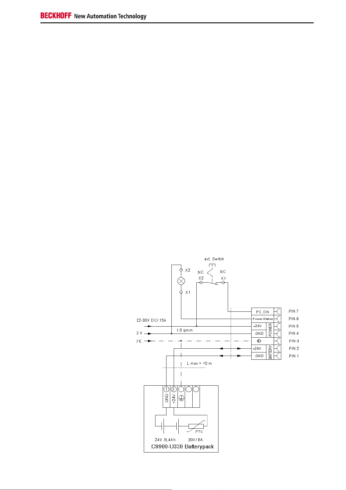
PC_ON, Power-Status
The circuit for shutting down the Industrial PC is realized using the inputsignal PC_ON and the output-signal Power-Status:
• The PC starts shutting down if 24 V exists at PC_ON, for example
using a switch.
• After shutting down, there is an output-voltage of 24 V at PowerStatus. This allows for example connecting an air gap switch for
disconnecting the system from power supply.
Wiring diagram
Wiring according to the wiring diagram (the circuit of PC_ON and PowerStatus is symbolical):
Wiring diagram external
switch and power supply
CP71xx 13
Page 16
Installation Instructions
Connecting devices
Warning
Fitted with the 24 VDC power supply unit:
Warning
The power supply plug must be withdrawn!
Please read the documentation for the external devices prior to connecting
them.
During thunderstorms, plug connector must neither be inserted nor
removed.
When disconnecting a plug connector, always handle it at the plug. Do not
pull the cable!
Connecting cables
The connections are located behind the outer housing of the Industrial PC
and are documented in the Product Description chapter.
When connecting the cables to the Industrial PC, proceed according to the
following sequence:
• Switch off all the devices that are to be connected.
• Disconnect all the devices that are to be connected from the power
supply.
• Connect all the cables between the Industrial PC and to the
devices that are to be connected.
• Connect all data transfer cables (if present) to the appropriate
plug-in receptacles of the data/telecommunication networks.
• Reconnect all devices to the power supply.
Check voltage rating and connect
1. Check that the external power supply is providing the correct
voltage.
2. Insert the power supply cable that you have assembled (see the
section Fitting the cable) into the Industrial PC's power supply
socket. Then connect it to your external 24 V power supply.
If a 24 V UPS is installed, the same type of rechargeable battery must
be used.
14 CP71xx
Page 17
Operating Instructions
Operating Instructions
Switching the Industrial PC on and off
Switch on
Shutting down and
switching off
Warning
Warning
Reset key
The Industrial PC does not have its own mains switch. The Industrial PC
will start when the equipment is switched on, or when it is connected to the
power supply.
When the plant is switched off, or when it is disconnected from its power
supply, the Industrial PC will be switched off.
Control software such as is typically used on Industrial PCs permits various
users to be given different rights. A user who may not close software may
also not switch the Industrial PC off, since data can be lost from the hard
disk by switching off while software is running.
First shut down, then switch off the PC!
If the Industrial PC is switched off as the software is writing a file to the
hard disk, the file will be destroyed. Control software typically writes
something to the hard disk every few seconds, so that the probability of
causing damage by switching off while the software is running is very high.
When you have shut down the Industrial PC, you have to switch off power
supply for at least 10 seconds before rebooting the system.
After resetting power supply the PC will start booting automatically.
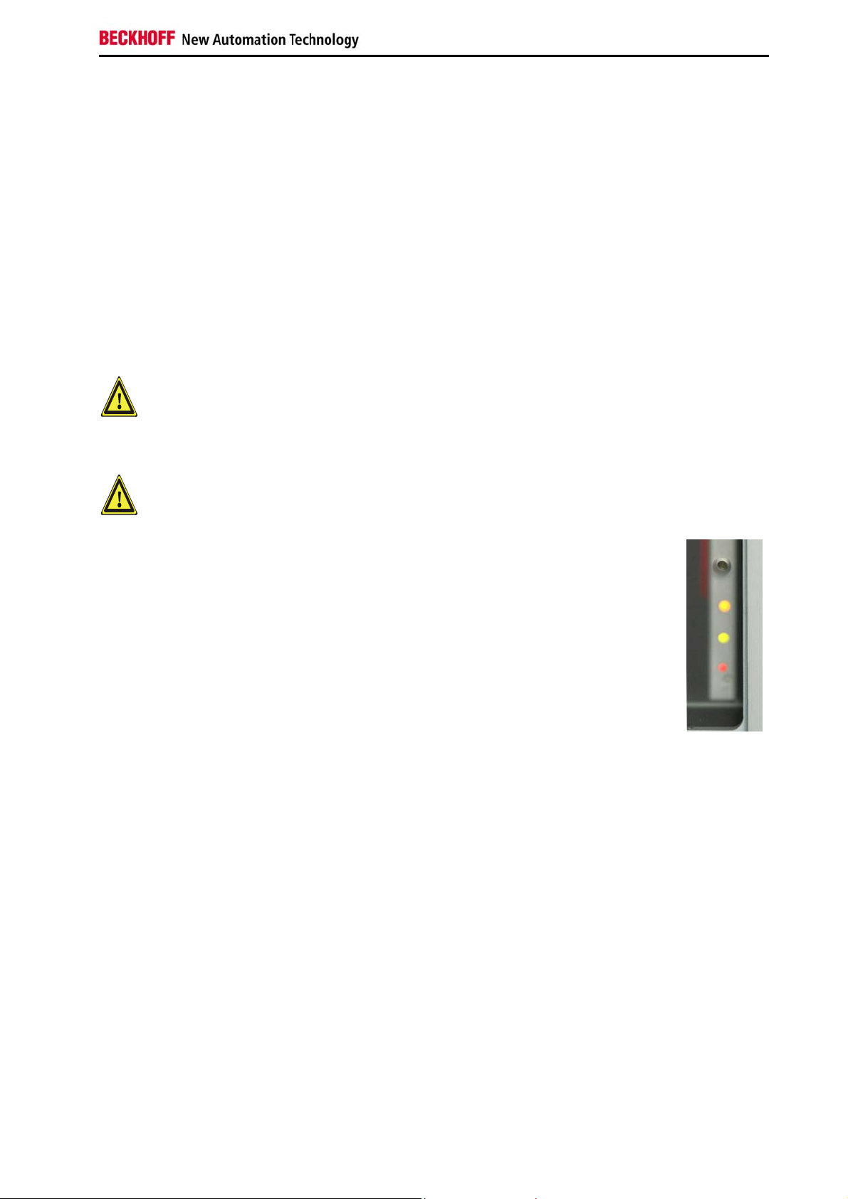
A Reset button (1) for rebooting the system is
provided behind the side door for the drives.
1
LEDs
2
Three LEDs are located next to the Reset button (2).
The red LED signalizes hard disk activity, the green LED signalizes the
presence of the voltage supply, while the yellow LED indicates Turbo
operation.
First switching on and driver installation
When you switch on the Industrial PC for the first time, the pre-installed
operating system (optional) will be started. In this case, all the required
drivers for any additional, optional hardware components ordered with the
PC will already have been installed.
If the PC was ordered without operating system, you have to install the
operating system and the driver software for any auxiliary hardware
yourself. Please follow the instructions in the documentation for the
operating system and the additional devices.
CP71xx 15
Page 18

Operating Instructions
UPS Software Components (optional)
Installing the UPS driver
software
Installation
Beckhoff information
system
i
Note
For operating the power supply unit as a UPS, the UPS driver software and
the associated UPS driver must be installed on the Industrial PC.
On delivery of the Beckhoff Industrial PC with operating system the
software is already installed. Should the software not be installed on your
PC, the drivers can be installed from the driver CD provided.
Installation on the PC
To install the UPS driver software, execute file
Beckhoff_UPS_vx.xx.xx.exe from the subdirectory of UPS\… from the
CD provided on the Industrial PC (Driver-archive for the Industrie-PC,
C9900-S700-xxxx). There you also find the help-file (TcUpsShellExt.chm)
before the installation of the software.
Start the driver-software (Start > Run > Program). The program is selfextracting and will guide the user through the installation routine.
Help files
The driver software comes with a detailed help function.
The help files can be called up either directly from the configuration register
by clicking the Help button, or under via Start > Programs > Beckhoff >
UPS software components.
Please note that the background illumination of the Panel is not switched
on in the case of activation power supply of the Industrial PC over the UPS.
In this case the Panel shows no picture.
16 CP71xx
Page 19

Operating Instructions
Maintenance
Danger
Danger
Please also refer to chapter General Notes.
Cleaning the Industrial PC
Switch off the Industrial PC and all connected devices, and disconnect the
Industrial PC from the power supply.
The Industrial PC can be cleaned with a soft, damp cloth. Do not use any
aggressive cleaning materials, thinners, scouring material or hard objects
that could cause scratches.
Replacing the battery on the motherboard
A used battery on the motherboard has to be replaced according to the
rules of the board manufacturer.
Danger of Explosion if battery is incorrectly replaced. Replace only with
same or equivalent type recommended by the manufacturer. Dispose of
used batteries according to the manufacturer's instructions.
Servicing
The Industrial PC requires no maintenance.
Shutting down
Dismantling the Industrial
PC
Observe national
electronics scrap
regulations
Disposal
The device must be fully dismantled in order to dispose of it. The housing
can be sent for metal recycling.
Electronic parts such as disk drives and circuit boards must be disposed of
in accordance with national electronics scrap regulations.
CP71xx 17
Page 20

Troubleshooting
Troubleshooting
i
Note
Please also refer to the section General Notes.
Pixel errors in the TFT display are production-caused and represent no complaint-reason!
Fault correction
Fault Cause Procedure
Nothing happens after the Industrial
PC has been switched on
The Industrial PC does not boot
fully
Computer boots, software starts,
but control does not operate
correctly
Floppy disk or CD access error Faulty disk or CD
The Industrial PC functions only
partially or only part of the time, e.g.
no or dark picture, but disk drive
responds when switching on
No power supply to the
Industrial PC
Other cause
Floppy disk or CD in the drive
Setup settings are incorrect
Other cause
Cause of the fault is either in the
software or in parts of the plant
outside the Industrial PC
Faulty disk drive
Defective components in the
Industrial PC
Check power supply cable
Call Beckhoff Service
Remove floppy disk or CD
and press any key
Check the setup settings
Call Beckhoff Service
Call the manufacturer of the
machine or the software
Check disk or CD in another
drive
Call Beckhoff Service
Call Beckhoff Service
18 CP71xx
Page 21

Troubleshooting
Service support
Quote the project number
Beckhoff and their partners around the world offer comprehensive service
and support, making available fast and competent assistance with all
questions related to Beckhoff products and system solutions.
Beckhoff Service
The Beckhoff Service Center supports you in all matters of after-sales
service:
• on-site service
• repair service
• spare parts service
• hotline service
Hotline:
Fax: +49(0)5246/963-479
e-mail: service@beckhoff.com
If servicing is required, please quote the project number of your Industrial
PC.
+49(0)5246/963-460
Beckhoff Support
Support offers you comprehensive technical assistance, helping you not
only with the application of individual Beckhoff products, but also with
other, wide-ranging services:
• world-wide support
• design, programming and commissioning of complex automation
systems
• and extensive training program for Beckhoff system components
Hotline:
Fax: +49(0)5246/963-9157
e-mail: support@beckhoff.com
+49(0)5246/963-157
Company headquarters
Beckhoff Automation GmbH
Eiserstraße 5
D-33415 Verl
Germany
Phone:
Fax: +49(0)5246/963-198
e-mail: info@beckhoff.com
The addresses of Beckhoff's branch offices and representatives round the
world can be found on the internet pages:
http://www.beckhoff.com
You will also find further documentation for Beckhoff components there.
+49(0)5246/963-0
CP71xx 19
Page 22

Assembly dimensions
Assembly dimensions
The illustrations show the measurements of the Panel-PCs. Please refer to
the tables for the dimensions of the Control Panel. All Dimensions in mm.
Display only
With function keys
Numerical keyboard
Alphanumerical keyboard
Mounting arm Rolec
Dimensions a b t
CP7100 10“ Display 353,8 308,3 29,5
CP7101 12“ Display 353,8 326,3 29,5
CP7102 13“ Display 426 395 30,5
CP7103 19“ Display 504 455 47
Dimensions a b t
CP7110 10“ Display 353,8 308,3 29,5
CP7111 12“ Display 353,8 326,3 29,5
CP7112 13“ Display 426 395 30,5
CP7113 19“ Display 504 455 47
Dimensions a b t
CP7120 10“ Display 406 308,3 29,5
CP7121-0000/1 12“ Display 406 308,3 29,5
CP7121-0002 12“ Display 439,8 308,3 29,5
CP7122 15“ Display 515 370,2 30,5
CP7123 19“ Display 563 426 47
Dimensions a b t
CP7130 10“ Display 403,4 368,2 29,5
CP7131-0000/1 12“ Display 406 370,2 29,5
CP7131-0002 12“ Display 426 370,2 29,5
CP7132 15“ Display 485 410,2 30,5
CP7133 19“ Display 504 535 47
20 CP71xx
Page 23

Appendix
Appendix
Technical data
Dimensions
Do not use the PC in areas
of explosive hazard
The following conditions must be observed during operation:
Environmental conditions
Shock resistance Sinusoidal vibration:
Protection class
Power supply
24 VDC power pack
EMC compatibility
Dimensions (W x H x D): 236 x 291 x 186 mm (without Control Panel)
Weight: 11,5 kg (basic configuration, without Control
Panel)
The Industrial PC must not be used where there is a risk of explosion.
Ambient temperature: 0 to 45°C
Atmospheric humidity: Maximum 95%, non-condensing
(EN 60068-2-6) 10 to 58 Hz: 0.035 mm
58 to 500 Hz: 0.5 G (~ 5 m/ s2)
During reading of CD-ROM: 10 to 58 Hz: 0.019 mm
58 to 500 Hz: 0.25 G (~ 2.5 m/ s
Impact:
(EN 60068-2-27/ -29)
During reading of CD-ROM:
Protection class: IP65
Supply voltage: 22–30V VDC
Power consumption: 100 W for the basic version
Resistance to interference: according to EN 61000-6-2
Emission of interference: according to EN 61000-6-4
5 G (~ 50 m/ s²), duration: 30 ms
5 G (~ 50 m/ s²), duration: 11 ms
2
)
Transport and storage
i
Note
FCC Approval for USA
FCC Approval for Canada
The same values for atmospheric humidity and shock resistance are to be
observed during transport and storage as in operation. Suitable packaging
of the Control Panel can improve the resistance to impact during transport.
The ambient temperature during storage and transport must be between
-20°C and +65°C.
Pixel errors in the TFT display are production-caused and represent no complaint-reason!
Approvals
FCC: Federal Communications Commission Radio Frequency Interference Statement
This equipment has been tested and found to comply with the limits for a
Class A digital device, pursuant to Part 15 of the FCC Rules. These limits
are designed to provide reasonable protection against harmful interference
when the equipment is operated in a commercial environment. This
equipment generates, uses, and can radiate radio frequency energy and, if
not installed and used in accordance with the instruction manual, may
cause harmful interference to radio communications. Operation of this
equipment in a residential area is likely to cause harmful interference in
which case the user will be required to correct the interference at his own
expense.
FCC: Canadian Notice
This equipment does not exceed the Class A limits for radiated emissions
as described in the Radio Interference Regulations of the Canadian
Department of Communications.
CP71xx 21
 Loading...