

Page 1
Installation and Operating instructions for
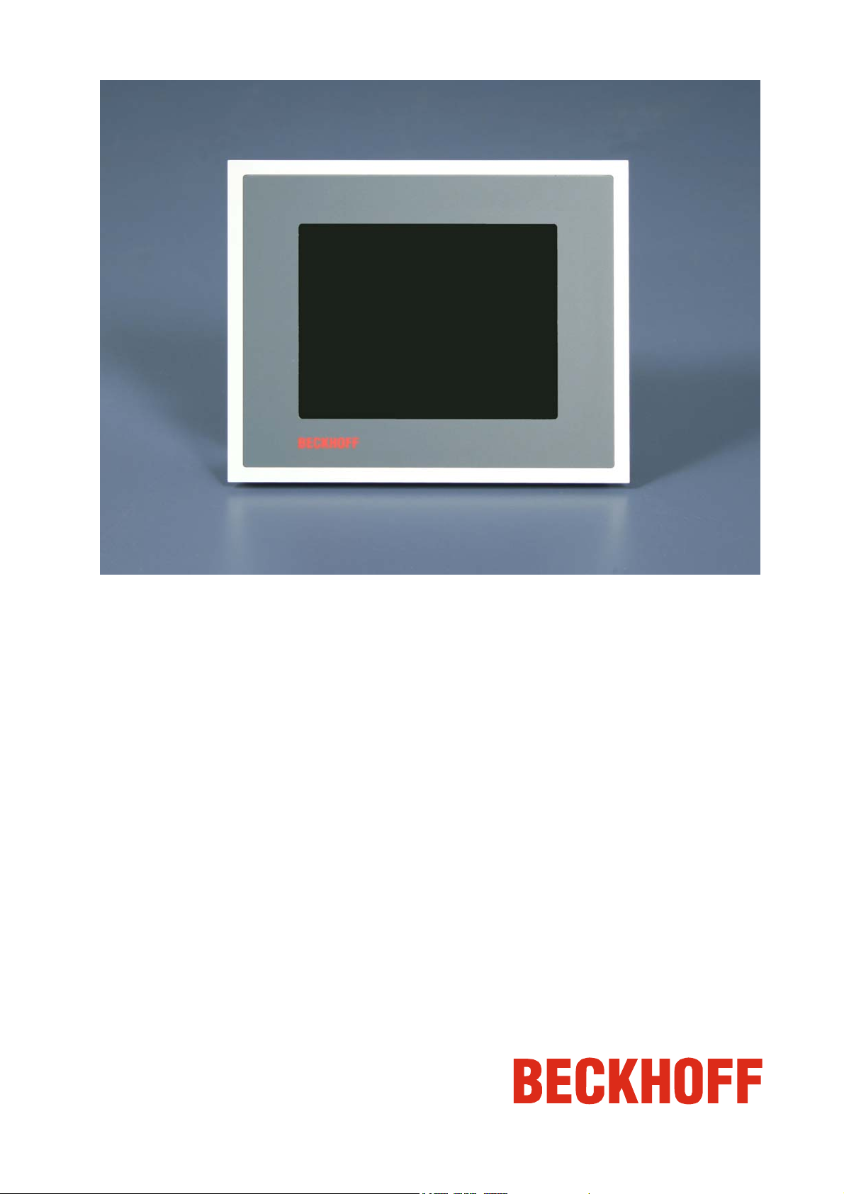
Built-in Control Panel CP6608
Version: 1.0
Date: 2008-02-07
Page 2

Page 3

General Notes
Table of contents
1.
General Notes 2
Notes on the documentation 2
Liability conditions 2
Description of safety symbols 2
Basic safety measures 3
Operator's obligation to exercise diligence 4
Operator requirements 4
2.
Product Description 5
Appropriate Use 5
Connections 5
Pin assignment 5
Connector description 6
Serial interface 6
USB interfaces 6
Network interfaces 6
Power supply 6
Status-LEDs 6
Ordering Option 6
3.
Installation Instructions 7
Transport and Unpacking 7
Transport 7
Unpacking 7
Assembly 8
Assembly dimensions 8
Mounting of the Control Panel 9
Fitting the cable 10
Cable Cross Sections 10
Material for assembling the connector 10
Assembling the connector 10
Connecting the Control Panel 11
Connecting cables 11
4.
Operating Instructions 12
Functional description 12
Servicing and maintenance 13
Cleaning the Control Panel 13
Replacing the battery on the motherboard 13
Servicing 13
Replacing the fluorescent lamps in the display 13
Emergency procedures 13
Shutting down 13
Disposal 13
5.
Troubleshooting 14
Fault correction 14
Service and Support 15
Beckhoff's branch offices and representatives 15
Beckhoff headquarters 15
Beckhoff Support 15
Beckhoff Service 15
6.
Appendix 16
Technical data 16
Approvals 16
FCC: Federal Communications Commission Radio Frequency Interference
Statement 16
FCC: Canadian Notice 16
CP6608 1
Page 4
General Notes
General Notes
Notes on the documentation
This description is only intended for the use of trained specialists in control
and automation engineering who are familiar with the applicable national
standards. It is essential that the following notes and explanations are
followed when installing and commissioning these components.
Liability conditions
The responsible staff must ensure that the application or use of the
products described satisfy all the requirements for safety, including all the
relevant laws, regulations, guidelines and standards.
The documentation has been prepared with care. The products described
are, however, constantly under development. For this reason, the
documentation may not always be have been fully checked for consistency
with the performance data, standards or other characteristics described.
None of the statements in this manual represent a guarantee for as set out
in § 443 of the German Civil Code or a statement about the assumed use
according to the contract as set out in § 434 para. 1 clause 1 no. 1 of the
German Civil Code. In the event that it contains technical or editorial errors,
we retain the right to make alterations at any time and without warning. No
claims for the modification of products that have already been supplied
may be made on the basis of the data, diagrams and descriptions in this
documentation.
© This documentation is protected by copyright. Any reproduction or third
party use of this publication, whether in whole or in part, without the written
permission of Beckhoff Automation GmbH, is forbidden.
Description of safety symbols
The following safety symbols are used in this operating manual. They are
intended to alert the reader to the associated safety instructions.
This symbol is intended to highlight risks for the life or health of personnel.
This symbol is intended to highlight risks for equipment, materials or the
environment.
This symbol indicates information that contributes to better understanding.
i
Danger
Warning
Note
2 CP6608
Page 5
General Notes
Basic safety measures
Before opening the control panel housing, and whenever the control
panel is not being used for control purposes (such as during
functional checks after a repair), all parts of the equipment must first
be switched off, after which the control panel is to be disconnected
from the equipment.
Disconnect the device by unplugging the connectors on the Control Panel
side.
Items of equipment that have been switched off must be secured
against being switched on again.
Displays used for the control panel’s LC-display are operated with a
voltage of up to 1000 V, depending on type. For that reason:
The supply voltage must be disconnected before the housing of the
Control Panel is opened.
Assembly work on the Control Panel during operation may damage the
panel:
• if metal objects such as screws or tools fall onto operating circuit
boards.
• if connecting cables internal to the control panel are removed or
inserted during operation
i
Warning
Danger
Note
CP6608 3
Page 6

General Notes
Operator's obligation to exercise diligence
The operator must ensure that
• the Control Panel is only used for its intended purpose (see
Product Description section);
• the Control Panel is only operated in a sound condition and in
working order;
• the instruction manual is in good condition and complete, and
always available for reference at the place of installation of the
Control Panel;
• the Control Panel is operated, maintained and repaired only by
suitably qualified and authorized personnel.
• the personnel is instructed regularly about relevant occupational
safety and environmental protection aspects, and is familiar with
the operating manual and in particular the safety notes contained
herein.
• none of the safety and warning notes attached to the Control Panel
are removed, and all notes remain legible.
National regulations
depending on the machine
type
Procedure in the event of a
fault
Depending on the type of machine and plant in which the Control Panel is
used, national regulations governing the controllers of such machines will
apply, and must be observed by the operator. These regulations cover,
amongst other things, the intervals between inspections of the controller.
The operator must initiate such inspections in good time.
In the event of faults at the Control Panel, the list in the section
Troubleshooting can be used to determine the measures to be taken.
Operator requirements
Read the operating
instructions
Software knowledge
Anyone who uses the Control Panel must have read these operating
instructions.
Every user must be familiar with all the functions of the software installed
on the Control Panel to which he has access.
4 CP6608
Page 7

Product Description
Product Description
Appropriate Use
The CP6608 Control Panel is designed for industrial application in machine
and plant engineering. A steel plate housing with aluminum front contains a
TFT display and a touch screen (optional).
The Control Panel is installed in the front of control cabinets.
Do not use the Control
Panel in areas of explosive
hazard
Control Panel CP6608
connections
X 102
Serial interface
X103, X104
USB out
The Control Panel must not be used where there is a risk of
explosion.
Connections
X 102
Pin assignment
D-SUB plug 9-pin (RS 232)
X105
Pin Signal Pin Signal
1
2
3
4
5
Pin Signal Pin Signal
1
2
X106
CD
RxD
TxD
DTR
GND
5V
D-
X107
6
7
8
9
3
4
DSR
RTS
CTS
RI
D+
GND
USB Type-A twin circuit board mounting
(FCI 72309-0030B USB Double Receptacle
A-Type)
X 105, X 106
Network
X107
Power
RJ-45 connector (Ethernet 10/ 100 MBit)
Socket 5-pol RM3.50 Sw Screw Clamp
BL3.5/180F (WEIDMÜLLER 1615810000)
Pin Signal Pin Signal
Housing
1
2
3
4
Pin Function
1
NC
2
NC
3
4
-
5
+
Screen
TD +
TD RD +
n.c.
24 V DC
Power Supply
5
6
7
8
n.c.
RD n.c.
n.c.
CP6608 5
Page 8

Product Description
Connector description
Serial interface
COM1
USB out
Network
Power
Description of the StatusLEDs
Serial interface
The Control Panel is equipped with a COM1 (X 102) serial interface (Type
RS232) for the connection of serial peripheral devices.
USB interfaces
The two USB interfaces (X 103, X104) (connector type A) are used for
connecting peripheral devices with USB connection.
USB2.0 standard is supported.
Network interfaces
The RJ-45 sockets (X 105, X 106) enable connection of the Control Panel
to a 10/ 100 MBit Ethernet network.
Power supply
The power supply for the Control Panel is established via the
socket (X 107).
Status-LEDs
P101
P102
The Status-LEDs are located near the Power Connector.
P101
P102
- -
24 V in Power Supply is established
Ordering Option
Option
C9900-E197
“Economy"-Einbau-Control-Panel CP6608
Version: Building Automation
18 pin connector instead of RS232 serial port with 2 digital inputs for
24 V, 2 digital outputs for 24 V, PT100 sensor input, stereo sound line out
and microphone in
6 CP6608
Page 9

Installation Instructions
Installation Instructions
Please also refer to chapter General Notes.
Transport and Unpacking
The specified storage conditions must be observed (see chapter Technical
data).
Transport
Despite the robust design of the unit, the components are sensitive to
strong vibrations and impacts. During transport, your Control Panel should
therefore be protected from excessive mechanical stress. Therefore,
please use the original packaging.
Danger of damage to the unit!
Warning
If the device is transported in cold weather or is exposed to extreme
variations in temperature, make sure that moisture (condensation) does not
form on or inside the device.
Prior to operation, the unit must be allowed to slowly adjust to room
temperature. Should condensation occur, a delay time of approximately 12
hours must be allowed before the unit is switched on.
Unpacking
Proceed as follows to unpack the unit:
1. Remove packaging.
2. Do not discard the original packaging. Keep it for future relocation.
3. Check the delivery for completeness by comparing it with your order.
4. Please keep the associated paperwork. It contains important
information for handling the unit.
5. Check the contents for visible shipping damage.
6. If you notice any shipping damage or inconsistencies between the
contents and your order, you should notify Beckhoff Service.
CP6608 7
Page 10

Installation Instructions
Assembly
Control Panel CP6608
Assembly dimensions
All dimensions are in mm.
Required cutout
8 CP6608
Page 11

Installation Instructions
Mounting of the Control Panel
Please refer to the chapter Assembly dimensions for Control Panel cutout
dimensions.
Mounting of the Control
Panel with 4 clamping
levers
Release clamping levers,
Folding them out
Insert the Control Panel into the
cutout.
Release the clamping levers with a
No. 2.5 Allen key.
Turn the clamping levers to the side
through 90°
and retighten them.
and retighten the screws.
CP6608 9
Page 12

Installation Instructions
Fitting the cable
Wiring
Fit the cables for the power supply of the Control Panel, using the included
material for assembling the connectors.
Cable Cross Sections
Note cable cross sections,
avoid voltage drop!
Insert Fuse The power supply must be protected with maximum 16 A.
Material for assembling the connector
Fitting the connector to the
cable
Applying the strain relief
Putting in the plug
connector
Fixing the upper part of the
stain relief housing
For the connection of the power supply, wiring with a cable-cross-section
of 1.5 mm
2
must be used.
With bigger distances between voltage source and Control Panel, you take
the voltage drop as a function of the cable-cross-section as well as voltage
fluctuations of your distribution voltage into account, so that is secured that
the voltage doesn't fall under 22 V at the power supply.
Material for assembling the connector
Plug connector 5-pole
Stain relief housing with lacing cord
Assembling the connector
So the connector is fitted to the cable:
1. Strip insulation from the cable ends (Length of stripped conductor
is 8 - 9 mm).
2. Screw together the cable ends in the 5-pole plug connector in
accordance with wiring diagram.
Thread the lacing cord into that
lower part of the stain relief housing.
Put the plug connector into that
lower part of the stain relief housing.
Tighten the lacing cord and pinch off
the plastic strap.
Fix the upper part of the stain relief
housing by snapping it onto the
lower part.
10 CP6608
Page 13

Installation Instructions
Connecting the Control Panel
The Control Panel must never be connected or disconnected in an area
Danger
Warning
that is subject to explosion hazard! Risk of explosion!
The mains plug of the Control Panel must be disconnected!
Please read the documentation for the external devices prior to connecting
them.
During thunderstorms, plug connector must neither be inserted nor
removed.
When disconnecting a plug connector, always handle it at the plug. Do not
pull the cable!
Connecting cables
The connections are located at the rear side of the Control Panel and are
documented in the Product Description section.
When connecting cables to the Control Panel, please adhere to the
following order:
• Switch the Control Panel off
• Disconnect the Control Panel from the power supply
• Connect all cables at the Control Panel and at the devices to be
connected
• Ensure that all screw connections between connectors and
sockets are tight!
• Reconnect all devices to the power supply.
CP6608 11
Page 14

Operating Instructions
Operating Instructions
Please also refer to chapter General Notes.
Functional description
Switch on
Switching off
The Control Panel does not have its own mains power switch. As soon as
the power supply is switched on the control panel is activated.
Control software, as typically applied in Industrial PCs, enables the
assignment of different rights to all users. A user who is not entitled to shut
down the software may not switch off the Industrial PC as an attempt to
shut it down when the software is running could result in the loss of
software data on the memory.
If the Industrial PC is shut down while the software is writing a file to the
memory, the file will be destroyed. Control software typically writes
something to the memory every few seconds, so that the probability of
causing damage by switching off while the software is running is very high.
i
Note
The touch screen may only be actuated by finger tips or with the touch
screen pen. The operator may wear gloves but there must be no hard
particles such as metal shavings, glass splinters embedded in the glove.
12 CP6608
Page 15

Operating Instructions
Please also refer to chapter General Notes.
First switch off the Control
Panel
The front of the Control Panel can be cleaned with a soft, damp cleaning
Servicing and maintenance
Cleaning the Control Panel
Switch off the Control Panel and all devices connected to it, so that keys
cannot be unintentionally actuated.
cloth. Do not use any aggressive cleaning materials, thinners, scouring
material or hard objects that could cause scratches.
Replacing the battery on the motherboard
A used battery on the motherboard has to be replaced according to the
rules of the board manufactorer.
The battery is located at
the upper side of the
Control Panel
Danger
Danger of Explosion if battery is incorrectly replaced. Replace only with
same or equivalent type recommended by the manufacturer. Dispose of
used batteries according to the manufacturer's instructions.
Servicing
The Control Panel is maintenance-free.
i
Note
Replacing the fluorescent lamps in the display
Since fluorescent lamps represent a consumable item in a display, they
must be replaced after a few years, depending on the number of operating
hours.
The fluorescent lamps of the 5.7 inch display can only be replaced from
Beckhoff Service.
Emergency procedures
In case of fire, the control panel should be extinguished with powder or
nitrogen.
Shutting down
Dismantle the Control
Panel
Observe national
electronics scrap
regulations
Disposal
The device must be fully dismantled in order to dispose of it. The housing
can be sent for metal recycling.
Electronic parts such as lamps and circuit boards must be disposed of in
accordance with national electronics scrap regulations.
CP6608 13
Page 16

Troubleshooting
Troubleshooting
Please also refer to chapter General Notes.
Pixel errors in the TFT display are production-caused and represent
i
Note
Fault Cause Measures
The Control Panel shows no
function
The Control Panel does not boot
fully
Computer boots, software starts,
but control does not operate
correctly
The Control Panel has only partial
function, or only functions some of
the time, for instance the picture is
dark or absent
no complaint-reason!
Fault correction
No power supply to Control Panel
Cable not connected
Setup settings are incorrect
Other cause
The cause of the error is in the
software or in parts of the
equipment outside the control panel
Faulty fluorescent bulb in the
display
Defective components in control
panel
Check power supply cable
1. Correctly connect cable
2. Call Beckhoff Service
Check the setup settings
Call Beckhoff Service
Call the manufacturer of the
machine or the software
Replacement of the
fluorescent tube in the
display from Beckhoff
Service
Call Beckhoff Service.
14 CP6608
Page 17

Troubleshooting
Service and Support
Beckhoff and their partners around the world offer comprehensive service
and support, making available fast and competent assistance with all
questions related to Beckhoff products and system solutions.
Beckhoff's branch offices and representatives
Please contact your Beckhoff branch office or representative for local
support and service on Beckhoff products!
The addresses of Beckhoff's branch offices and representatives round the
world can be found on her internet pages:
Quote the project number
http://www.beckhoff.com
You will also find further documentation
Beckhoff headquarters
Beckhoff Automation GmbH
Eiserstraße 5
D-33415 Verl
Germany
Phone: +49(0)5246/963-0
Fax: +49(0)5246/963-198
e-mail: info@beckhoff.com
Beckhoff Support
Support offers you comprehensive technical assistance, helping you no
only with the application of individual Beckhoff products, but also with
other, wide-ranging services:
• world-wide support
• design, programming and commissioning of complex automation
systems
• and extensive training program for Beckhoff system components
Hotline:
Fax: +49(0)5246/963-9157
e-mail: support@beckhoff.com
+49(0)5246/963-157
Beckhoff Service
The Beckhoff Service Center supports you in all matters of after-sales
service:
• on-site service
• repair service
• spare parts service
• hotline service
Hotline:
Fax: +49(0)5246/963-479
e-mail: service@beckhoff.com
If servicing is required, please quote the project number of your Industrial
PC.
+49(0)5246/963-460
for Beckhoff components there.
CP6608 15
Page 18

Appendix
Appendix
Technical data
Dimensions
Operation in areas that are
subject to explosion hazard
The following conditions must be observed during operation:
Environmental conditions
Shock resistance Sinusoidal vibration:
Protection class
Power supply
EMC compatibility
Transport and storage
Dimensions (W x H x D): see section Assembly dimensions.
Weight: 1.2 kg
The Control Panel must not be used where there is a risk of
explosion.
Ambient temperature: 0 to 55°C
Atmospheric humidity: Maximum 95%, non-condensing
(EN 60068-2-6)
58 to 500 Hz: 0.5 G (~ 5 m/ s2)
Impact:
(EN 60068-2-27/ 29)
Front side: IP65
Rear side: IP20
Supply voltage: 24 V
Power consumption: contact Beckhoff Service
Resistance to interference: conforms to EN 61000-6-2
Emission of interference: conforms to EN 61000-6-4
The same values for atmospheric humidity and shock resistance are to be
observed during transport and storage as in operation. Suitable packaging
of the Control Panel can improve the resistance to impact during transport.
The ambient temperature during storage and transport must be between
-20°C and +65°C.
10 to 58 Hz: 0.035 mm
5 G (~ 50 m/ s²), duration: 30 ms
(22 – 30 VDC)
DC
i
Note
FCC Approval for USA
FCC Approval for Canada
Pixel errors in the TFT display are production-caused and represent no complaint-reason!
Approvals
FCC: Federal Communications Commission Radio Frequency Interference Statement
This equipment has been tested and found to comply with the limits for a
Class A digital device, pursuant to Part 15 of the FCC Rules. These limits
are designed to provide reasonable protection against harmful interference
when the equipment is operated in a commercial environment. This
equipment generates, uses, and can radiate radio frequency energy and, if
not installed and used in accordance with the instruction manual, may
cause harmful interference to radio communications. Operation of this
equipment in a residential area is likely to cause harmful interference in
which case the user will be required to correct the interference at his own
expense.
FCC: Canadian Notice
This equipment does not exceed the Class A limits for radiated emissions
as described in the Radio Interference Regulations of the Canadian
Department of Communications.
16 CP6608
 Loading...