

Page 1
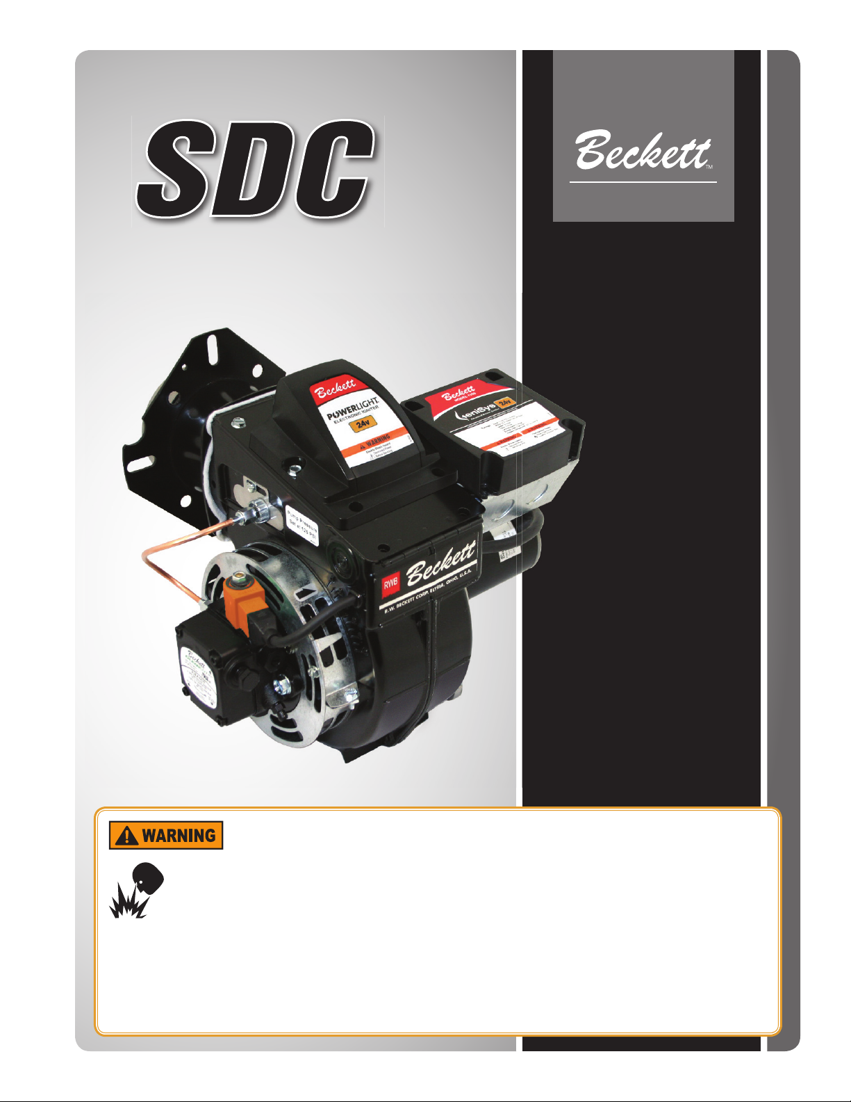
24 Vdc Oil Burner Manual
CORPORATION
Potential for Fire, Smoke and Asphyxiation Hazards
Incorrect installation, adjustment, or misuse of this burner could result in death, severe
personal injury, or substantial property damage.
To the Homeowner or Equipment Owner:
Please read and carefully follow all instructions
y
provided in this manual regarding your responsibilities
in caring for your heating equipment.
Contact a professional, qualifi ed service agency for
y
installation, start-up or service work.
READ THESE INSTRUCTIONS AND SAVE FOR
y
REFERENCE.
To the Professional, Qualifi ed Installer or Service
Agency:
Please read and carefully follow all manual instructions
y
and any supplements provided, before installing,
starting, or servicing this burner or heating system.
The Installation must be made in accordance with all
y
state and local codes having jurisdiction.
Page 2
Contents
Burner Application Scope and Intended Use ...........2
Prepare Before Installing ............................................ 3
Notice Special Requirements.............................................3
Specifi cations .....................................................................3
Hazard Defi nitions
Indicates a hazardous situation,
which, if not avoided, will result
in death or serious injury.
General Information ....................................................4
A. Equipment Located in Confi ned Space ......................... 4
Exhaust Fans and Other Air-Using Devices. ...................... 4
B.
C. Clearances to Burner and Equipment ...........................4
D. Exhausting Hazardous Fumes ......................................4
Nozzle Assembly Maintenance .................................. 4
A. Replace the Burner Nozzle............................................4
B. Check/Adjust Electrodes ...............................................5
C. Igniter Maintenance .......................................................6
D. Servicing Nozzle Line Assembly ...................................6
E. Check/Adjust “Z” Dimension ..........................................6
Fuel Supply ..................................................................7
A. Connect Fuel Lines........................................................7
B. Fuel Supply Level with or Above Burner........................7
C. Fuel Supply Below Level of Burner ...............................7
D. Fuel Line Replacement (Remote Tank Only) ................7
E. Fuel Line Valve and Filter ............................................. 7
Burner Wiring ...............................................................8
A. Burner installed on equipment .......................................8
B. Burner Replacement......................................................8
Drive Component Maintenance .................................. 9
A. Motor, Blower Wheel, & Coupling Replacement............9
B. Pump Maintenance........................................................9
C. Solenoid Valve Testing ................................................10
Indicates a hazardous situation,
which, if not avoided, could
result in death or serious injury.
Indicates a hazardous situation,
which, if not avoided, could
result in minor or moderate injury.
Within the boundaries of the hazard warning, there will
be information presented describing consequences if the
warning is not heeded and instructions on how to avoid
the hazard.
Intended to bring special attention
to information, but not related to
personal injury or property damage.
Start Up Burner & Set Combustion ..........................10
A. Basic Burner Operation ...............................................10
B. Combustion Set-up ......................................................10
C. Set Combustion with Instruments................................10
Maintain & Service Burner ........................................ 11
A. Owner’s Information ....................................................11
B. Owner Service and Maintenance ...............................11
C. Extended Down Time .................................................. 11
D. Regular Service/Maintenance ..................................... 11
Troubleshooting ........................................................12
Replacement Parts ....................................................14
Limited Warranty Information ..................................16
Burner Application Scope
and Intended Use
The SDC burner is designed for use in road
maintenance equipment applications that
have DC voltage charging systems capable of
sustaining the specifi ed voltage requirements.
For other equipment applications, please contact
Beckett Technical Services at 1-800-645-2876.
2
Page 3
Section: Prepare Before Installing
Prepare Before Installing
Owner’s Responsibility
Incorrect installation, adjustment, and
use of this burner could result in severe
personal injury, death, or substantial
property damage from fi re, carbon
monoxide poisoning, soot or explosion.
Contact a professional, qualifi ed service agency for the
installation, adjustment and service of your oil heating
system. This work requires technical training, trade
experience, licensing or certifi cation in some states and
the proper use of special combustion test instruments.
Please carefully read and comply with the following
instructions:
Never store or use gasoline or other fl ammable liquids
y
or vapors near this burner or appliance.
Never attempt to burn garbage or refuse in this
y
appliance.
Never attempt to light the burner/appliance by throwing
y
burning material into the appliance.
Never attempt to burn any fuel not specifi ed and
y
approved for use in this burner.
y
Never restrict the air inlet openings to the burner or
the combustion air ventilation openings in the room.
Impaired Burner Performance
and Fire Hazard.
Specifi cations
See ‘Adequate Voltage Required’ warning on page 4
Rated Voltage: 27 Vdc (Nominal Charging System Voltage)
Reference Voltage: 24 Vdc (Battery Discharge Voltage)
Capacity Firing Rate (27V): 1.75 – 5.50 GPH
Input: 245,000 - 770,000 Btu/h
Firing Rate (24V)*: 1.75 - 5.00 GPH
Input: 245,000 - 700,000 Btu/h
Fuels USA: No. 1 or No. 2 diesel fuel or kerosene;
No.1 or No. 2 heating oil (ASTM D396)
DO NOT USE
GASOLINE, CRANKCASE OIL, OR
ANY OIL CONTAINING GASOLINE.
Electrical Burner Voltage (nominal): 27 Vdc
Voltage Range: 21.6V - 28V
Operating Load
w/ igniter on: 14 Amps
w/ igniter off: 10 - 12 Amps
Motor Voltage (nominal): 27 Vdc
Voltage Range: 21.6V - 30V
Full Load Amps: 10 Amps
Starting Amps: 50 Amps Max.
1/4 HP, 3400 RPM, NEMA “N” Flange
Igniter Voltage (nominal): 24 Vdc
Voltage range: 21.6V - 32V
Current: 1.2 Amps
Ignition Secondary: 19kVpk 35mA
Interrupted OR intermittent duty
Valve Coil Voltage: 24 Vdc
Current: < 0.5A
Do NOT operate the burner beyond specifi cations
outlined in the table to the right.
For applications beyond these limits, consult Beckett
y
Technical Service at 1-800-645-2876.
y
NOTE: Some packaged appliances with burners
may be agency listed as a unit to operate beyond
these limits. Consult the appliance manufacturer’s
specifi cations and agency approvals for verifi cation.
Notice Special Requirements
If you discover damage to the burner
or controls during unpacking, notify
the carrier at once and fi le the appropriate claim.
When contacting Beckett for service
information — Please record the
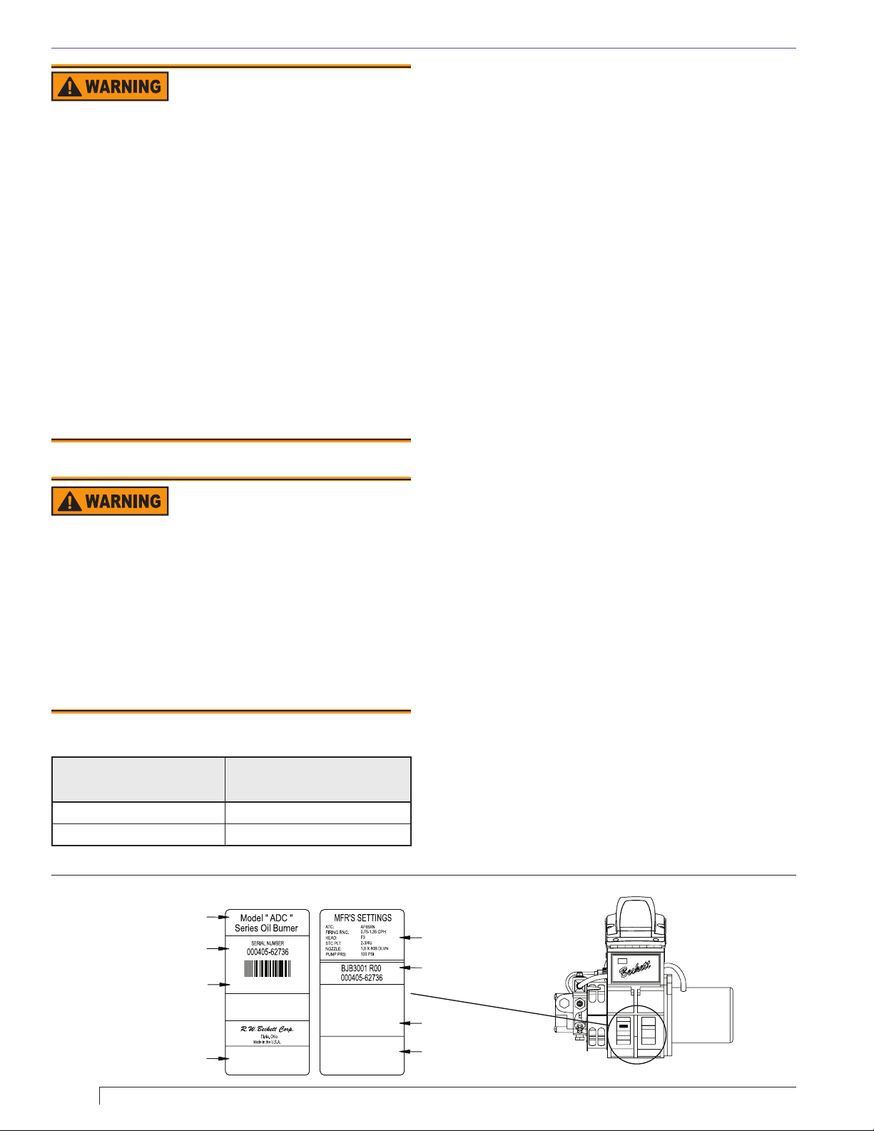
burner serial number (and have available when calling or
writing). You will fi nd the serial number on the silver label
located on the left rear of the burner. See Figure 1.
24 Vdc SDC Burner Manual
Pump Outlet pressure: Note 1
Dimensions Height (maximum): 11 ½ inches
Width (maximum): 14 3/8 inches
Depth (chassis only): 6 9/16 inches
Air tube diameter: 4 inches
Ambient
Operating
Temperature
*Firing rate capacity is based on airfl ow volume. In the SDC burner, airfl ow
volume and motor speed are proportional to the DC voltage. This results in a
lower maximum fi ring rate at 24V.
Note 1. See equipment manufacturer’s burner specifi cations for recommended
outlet pressure. Pressure is 100 psig unless otherwise noted.
+32° F. (0° C.) Minimum
+115° F. (+46° C.) Maximum
(See Warning on Impaired Burner
Performance and Fire Hazard.)
High altitude installations – Accepted
industry practice requires no derate
of burner capacity up to 2,000 feet above sea level. For
altitudes higher than 2,000 feet, derate the burner capacity
2% for each 1,000 feet above the 2,000 feet.
3
Page 4
Section: General Information & Nozzle Assembly Maintenance
Adequate Voltage Required
A low or erratic power supply could result in impaired
burner operation, severe delayed ignition or an
explosion inside the heat exchanger resulting in a
burn and/or asphyxiation hazard.
The Model SDC requires a continuous supply of 21.8 to
y
28 volts DC measured at the burner during operation with
a minimum supply & circuit capacity of 15A. See page 3
for maximum capacity and voltage specifi cations.
An automotive or small engine charging system that is
y
capable of supplying the required continuous voltage/
amperage is recommended with certain road equipment,
such as asphalt hot patchers and similar applications.
This is especially true while maintaining nominal load
y
temperatures during idle periods.
Once the burner is set-up at a specifi c voltage, a voltage
y
regulator shall be used to maintain that voltage within
+/- 1 Vdc during burner operation.
Adequate Combustion
and Ventilation Air Supply
Required
Failure to provide adequate air supply could seriously
affect the burner performance and result in damage to
the equipment, asphyxiation, explosion or fi re hazards.
The burner cannot properly burn the fuel if it is not
y
supplied with a reliable combustion air source.
Follow the guidelines in the latest editions of the NFPA
y
31 and CSA-B139 regarding providing adequate air
for combustion and ventilation.
General Information
Refer to the Troubleshooting section of this manual when
experiencing a possible fault condition.
A. Equipment Located in Confi ned Space
The confi ned space should have two permanent openings:
one near the top of the enclosure and one near the
bottom of the enclosure. Each opening shall have a free
area of not less then one square inch per 1,000 BTU’s
per hour of the total input rating of all equipment within
the enclosure. The openings shall have free access to the
building interior, which should have adequate infi ltration
from the outside.
B.
Exhaust Fans and Other Air-Using Devices.
Size air openings large enough to allow for all air using
devices in addition to the minimum area required for
combustion air. If there is any possibility of the equipment
room developing negative pressure (because of exhaust
fans, for example), either pipe combustion directly to the
burner or provide a sealed enclosure for the burner and
provide it with its own combustion air supply.
C. Clearances to Burner and Equipment
Provide space around burner and equipment for easy
service and maintenance. Check minimum clearances
against those shown by the equipment manufacturer and
by applicable codes.
D. Exhausting Hazardous Fumes
See warning on this page. Also be conscious of any fumes
produced by the materials that are being heated. Always
ensure adequate ventilation to exhaust all fumes.
Nozzle Assembly
Maintenance
Table 1. Combustion Head Firing Rates
Firing Rate GPH
(min - max)
Head
1.75 - 3.25 F22/F220
2.50 - 5.50 F310
Figure 1. Typical Burner Nameplate
General Model Information
Serial Number
Including Date Code
Rating Information
Primary Group
and Fuel Oil
4
A. Replace the Burner Nozzle.
If applicable, remove the plastic plug protecting the
1.
nozzle adapter threads.
Place a 3/4” open-end wrench on the nozzle adapter.
2.
Insert the nozzle into the adapter and fi nger tighten.
Finish tightening with a 5/8” open-end wrench.
R.W. Beckett
Manufacturer’s Settings
R.W. Beckett Specification
Number and Revision
Can Be Customized by
Individual Specification
State & Local Approvals
RWB
Model " AFG "
Series Oil Burner
000405-62736
R.W.Beckett Corp.
ELYRIA
OHIO U.S.A.
MFR'S SETTINGS
ATC:
AF65XN
FIRING RNG:
0.75-1.35 GPH
F3HEAD:
SERIAL NUMBER
STC PLT:
2-3/4U
NOZZLE:
1.0 X 80B DLVN
PUMP PRS: 100 PSI
BJB3001 R00
000405-62736
Elyria, Ohio
Made in the U.S.A.
SK10090
Page 5

Section: Nozzle Assembly Maintenance
Correct Nozzle and Flow
Rate Required
Incorrect nozzles and fl ow rates could
result in impaired combustion, underfi ring, over-fi ring, sooting, puff-back of
hot gases, smoke and potential fi re or
asphyxiation hazards.
Use only nozzles having the brand, fl ow rate (gph),
spray angle and pattern specifi ed by the appliance
manufacturer.
Follow the appliance manufacturer’s specifi cations for the
required pump outlet pressure for the nozzle, since this
affects the fl ow rate.
Nozzle manufacturers calibrate nozzle fl ow rates at
y
100 psig.
When pump pressures are higher than 100 psig, the
y
actual nozzle fl ow rate will be greater than the gph
stamped on the nozzle body. (Example: A 1.00 gph
nozzle at 140 psig = 1.18 gph)
Securely tighten the nozzle (90 torque inch pounds). For typical
nozzle fl ow rates at various pressures refer to Table 2.
If the nozzle is already installed, remove the nozzle
3.
line assembly to verify that the nozzle size and spray
pattern are correct for the application (per equipment
manufacturer’s information). Verify that the electrode
tip settings comply with Figure 3.
Use care when removing or
installing an oil nozzle
A damaged nozzle could cause impaired combustion,
sooting, puffback of hot gases, oil leakage and
potential fi re or asphyxiation hazards.
Inspect the nozzle adapter to insure that the sealing
y
surface is not grooved or scratched.
To insure that the nozzle functions properly, check the
y
orifi ce and strainer for dirt, scratches or other damage
before installation.
Do NOT attempt to install or remove a nozzle without
y
securing the adapter to prevent seriously damaging
the alignment.
Use care when handling the nozzle line assembly
y
to prevent changing the electrode tip settings or
damaging the ceramic electrode insulators.
Ensure the electrode settings match the values shown
y
in Figure 3.
B. Check/Adjust Electrodes
Check the electrode tip settings. Adjust if necessary
to comply with the dimensions shown in Figure 3. To
adjust, loosen the electrode clamp screw and slide/rotate
electrodes as necessary. Securely tighten the clamp
screw when fi nished.
Figure 2. Nozzle, Line & Electrode Assembly
Contacts to be parallel with
Electrode gap to be centered
with nozzle center.
horizontal center line within 2°.
Figure 3. Electrode Tip Setting
5/32” GAP
1/4” ABOVE
CENTER
1/8” NOZZLE-TO-TIP
SPACING
6
8
1
11
10
9
4
Item # Description
1 Electrode Contact (3” ATC or extension over 3”)
2 Nozzle Line
3 Spider spacer assembly
4 Static Plate
5 Electrode clamp
6 Electrode clamp retaining screws
7 Nozzle line setscrew
8 Electrode Insulator
9 Nozzle adapter
10 Nozzle tip
11 Electrode tip
2
7
Air Tube Length Dimension ‘S’
2-5/8” to 3” 1-3/8”
3-5/8” to 4-1/2” 1-5/8”
over 4-7/8” 2-13/32”
90°
3
5
4
24 Vdc SDC Burner Manual
5
Page 6
Section: Nozzle Assembly Maintenance
C. Igniter Maintenance
The igniter assembly does not require any adjustments
beyond making sure the springs and the burner electrode
rods make solid contact when the igniter is in the closed
position. The sealing surfaces of the gaskets should be
checked and replaced at the fi rst signs of any damage or
deterioration. Clean any dirt or residue from the porcelain
bushings, springs, and baseplate.
The simplest way to check igniter operation is by supplying
voltage to the input and checking to see whether an arc
is produced. Check by either looking or listening to see if
there is an arc across the electrodes while the burner is
running and the igniter is energized.
The igniter must be grounded to the burner before
checking the following. To check the igniter, ensure all
power to the burner is off and use an ohmmeter to check
the resistance between the two springs. The meter should
read between 480 - 580 ohms.
The igniter should be replaced if the meter indicates an
open circuit, or the spring-to-spring resistance exceeds
the 480 - 480 ohms range by more than 10%.
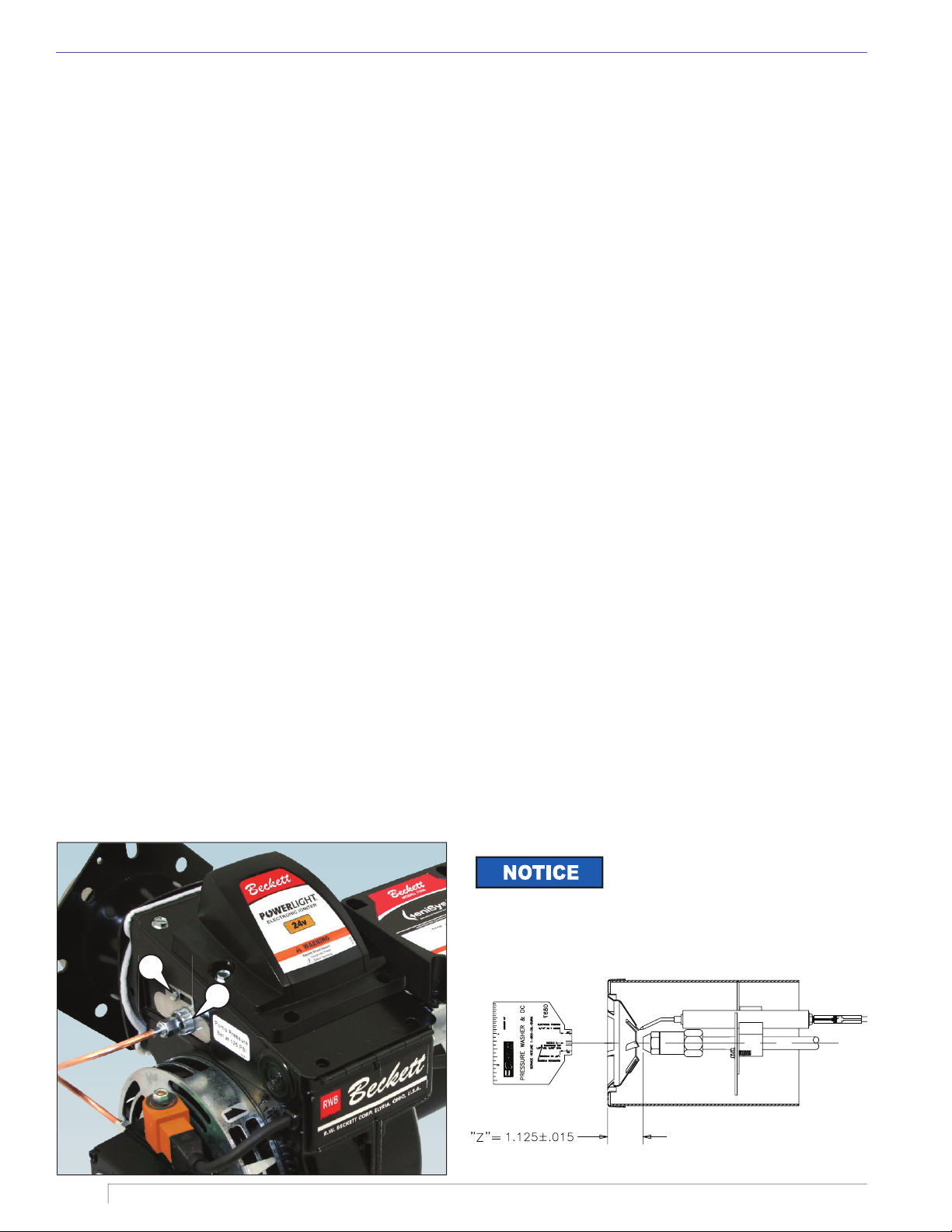
D. Servicing Nozzle Line Assembly
Before proceeding, turn off power to the burner.
Disconnect the oil connector tube from the nozzle
1.
line.
Referring to Figure 4, loosen the two screws securing
2.
the igniter retaining clips (a) and rotate both clips to
release the igniter baseplate. Then tilt the igniter
back on its hinge.
Remove the splined nut (b).
3.
Remove the nozzle line assembly from the burner,
4.
being careful not to damage the electrodes or
Figure 4. Igniter Retainer Screws
insulators while handling. To ease removal of short
assemblies, it may be necessary to loosen the
escutcheon plate (c). Reset to the edge of the label.
To replace the nozzle line assembly, reverse the
5.
above steps.
E. Check/Adjust “Z” Dimension
Refer to Figure 5. The critical “Z” dimension is the
distance from the face of the nozzle to the fl at face of
the head. This distance for F heads is 1-1/8”. The “Z”
dimension is factory set for burners shipped with the air
tube installed but should always be verifi ed during service
and installation. If the “Z” dimension is out of adjustment,
perform the following steps.
Before proceeding, turn off power to the burner.
Disconnect the oil connector tube from the nozzle
1.
line.
Referring to Figure 4, loosen the splined nut (a)
2.
from the nozzle line. Loosen the hex head screw
(b) securing the escutcheon plate to the burner
housing.
A Beckett T650 gauge should be used to set the Z
3.
dimension.
Place the end of a ruler at the face of the nozzle and,
4.
using a straight edge across the head, measure the
distance to the face of the head.
Slide the nozzle line forward or back until this
5.
dimension for F heads is 1-1/8”.
Tighten the hex head screw to secure the escutcheon
6.
plate to the burner chassis. Then tighten the splined
nut and attach the oil connector tube.
Recheck the “Z” dimension periodically when
7.
servicing to ensure the escutcheon plate has not
shifted. You will need to reset the “Z” dimension if
you replace the air tube or nozzle line assembly.
The Beckett Z gauge (part number Z-
2000) is available to permit checking
the F head “Z” dimension without removing the burner.
Figure 5. ‘Z’ Dimensions Using Gauge
b
a
SK9787
6
Page 7
Fuel Supply
Section: Fuel Supply
A. Connect Fuel Lines
For oil supply system specifi cations for tanks not mounted
on machines, carefully follow the pump manufacturer’s
literature and the latest edition of the National Fire
Protection Association (NFPA) 31 standard.
Do Not Install Bypass Plug
with 1-Pipe System
Failure to comply could cause Immediate pump seal
failure, pressurized oil leakage and the potential for a
fi re and injury hazard.
The burner is shipped without the bypass plug installed.
y
Install the bypass plug in two-pipe oil supply systems
y
ONLY.
Oil Supply Pressure
Control Required
Damage to the fi lter or pump seals could cause oil
leakage and a fi re hazard.
The oil supply inlet pressure to the burner cannot
y
exceed 3 psig.
Insure that a pressure limiting device is installed in
y
accordance with the latest edition of NFPA 31.
Do NOT install valves in the return line. (NFPA 31,
y
Chapter 8.)
Gravity Feed Systems: Always install an anti-siphon
y
valve in the oil supply line or a solenoid valve (RWB
Part # 22246U) in the pump/nozzle discharge tubing
to provide backup oil fl ow cut-off protection.
Do Not Use Tefl on Tape
B. Fuel Supply Level with or Above Burner
Pumps with automatic bypass do
not require a bypass plug. Verify
by referring to the pump manufacturer’s instructions.
The burner may be equipped with a single stage pump.
If a one-pipe system is installed, verify a bypass plug is
not installed in the pump, then connect the fuel supply
to the burner with a single supply line Note that manual
bleeding of the pump is required on initial start-up or
when the equipment runs out of fuel. When connecting
a two-pipe fuel system, install the pump bypass plug.
C. Fuel Supply Below Level of Burner
When the fuel supply is more than eight feet below
the level of the burner, a two-pipe fuel supply system
is required. Depending on the fuel line diameter and
the horizontal and vertical length, the installation
may also require a two-stage pump. Consult the
fuel unit manufacturer’s literature for lift and vacuum
capability.
D. Fuel Line Replacement (Remote Tank Only)
When replacing fuel lines, continuous lengths of heavy
wall copper tubing is recommended. To ensure a tight
seal, always use fl are fi ttings. Never use compression
fi ttings. Always install fi ttings in an accessible location.
To avoid vibration noise, fuel lines should not run
against the appliance or the ceiling joists.
Damage to the pump could cause impaired burner
operation, oil leakage and appliance soot-up.
Never use Tefl on tape on fuel oil fi ttings.
y
Tape fragments can lodge in fuel line components
y
and fuel unit, damaging the equipment and preventing
proper operation.
Use oil-resistant pipe sealant compounds.
y
24 Vdc SDC Burner Manual
E. Fuel Line Valve and Filter
Shutoff valves should be located in the oil supply line.
Do not install valves in the return line.
7
Page 8
Section: Burner Wiring
Burner Wiring
Explosion, Fire, Scald, &
Burn Hazard
All heating equipment must have HIGH
LIMIT controls to protect against excessive
temperature and/or pressure. The control
must interrupt electrical power and shutdown the
burner, if operating or safety controls fail and cause a
runaway condition.
Follow the equipment manufacturer’s wiring diagrams
y
and note all required safety controls.
Typical safety controls include high temperature or
y
pressure limits, low water cutoffs, pressure relief
valves and blocked fl ue sensing switches.
Verify all limit and safety controls are installed and
y
functioning correctly, as specifi ed by the manufacturer,
applicable safety standards, codes and all authorities
having jurisdiction.
Ensure the equipment is free of oil and oil vapor
y
before starting or resetting the burner.
Do not wire power directly to the burner motor. Only
y
wire the motor as shown in Figure 6. If instant burner
heat is required by the application, purchase or
program a control with a long motor-off delay time,
which will ensure instant heat if a new call for heat
is received within the motor-off delay time.
Electrical Shock Hazard
Electrical shock can cause severe personal injury or
death.
Remove all jewelry, such as rings and watches before
y
performing service.
Disconnect electrical power before installing or
y
servicing the burner.
Provide ground wiring to the burner, metal control
y
enclosures and accessories. (This may also be
required to aid proper control system operation.)
A. Burner installed on equipment
Refer to appliance manufacturer’s wiring diagram for
electrical connections. Refer to “Maintain & Service
Burner” section near the end of this manual.
B. Burner Replacement
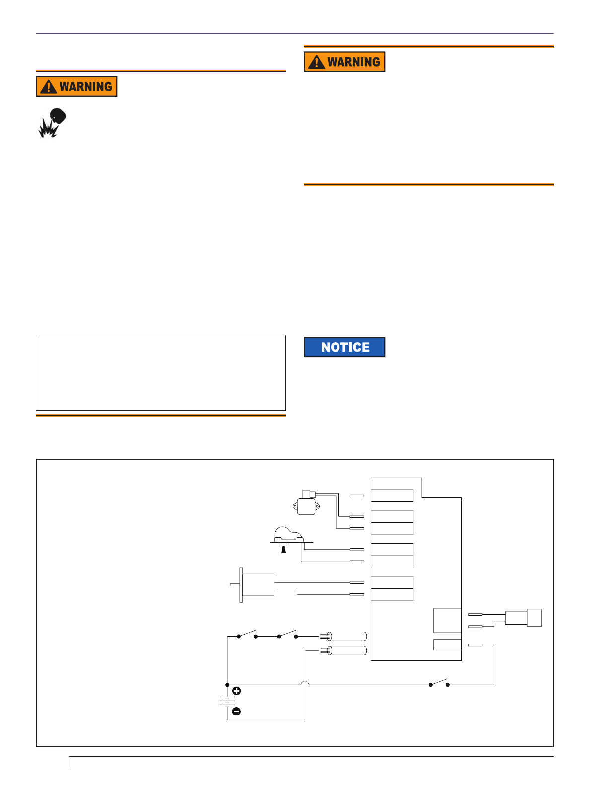
Burner wiring may vary, depending on the actual primary
control and furnished options. Refer to Figure 6 for typical
burner wiring.
Variations to the burner circuits may
occur due to optional temperature,
pressure, and vacuum switches that control burner
operation. Note that when external switches are used to
control motor operation they must be sized correctly for
the rated current or a relay should be installed to isolate
the switches from the motor’s full load current.
Figure 6. Wiring with 7559 Control
Notes:
Wires are to be sized to prevent a
1.
voltage drop between the battery and
the burner with the burner running at
full load.
Fuse Sizes(inside control):
2.
Motor = 20 Amp; Igniter, Control,
Valve, & Alarm = 7.5 Amp
Hard-wire burner ground to battery.
3.
Do NOT use chassis ground system.
Input power to the control’s +24 volt
4.
wire shall be provided from a fused
service switch, rated at 50 amps or
less.
Motor-off delay on a 7559P will be
5.
disabled if the safety and operating
limits as shown in Figure 6 interrupt
power to the control’s red +24 volt
wire.
Do not wire power directly to the
6.
burner motor. Only wire the motor as
shown in Figure 6. If instant burner
heat is required by the application,
purchase or program a control with a
long motor-off delay time, which will
ensure instant heat if a new call for
heat is received within the motor-off
delay time.
MAIN
POWER
24V
IGNITER
MOTOR
ON/OFF/RESET
VALV E
HIGH
LIMIT
OIL
RED WIRE
BLACK WIRE
ALARM
VALV E
GND (VLV)
IGNITER
GND (IGN)
MOTOR
GND (MTR)
CAD
CELL
ENABLE
THERMOSTAT
CAD CELL
8
Page 9
Section: Drive Component Maintenance
Drive Component
Maintenance
A. Motor, Blower Wheel, & Coupling
Replacement
The motor will require replacement if the proper voltage is
measured at the motor input, and the motor will either not
run, or the current draw with a free running pump exceeds
10% of the rated current.
To replace the burner motor, coupling and/or blower wheel
perform the following steps.
Before servicing, turn off and/or disconnect all power
1.
to the burner.
Disconnect the burner motor wires.
2.
Remove the bolts securing the motor to the burner
3.
housing.
Remove the motor, coupling, and blower wheel.
4.
Loosen the set screw on the blower wheel to slide
5.
the existing wheel off the shaft.
Slide the new blower wheel onto the old shaft (after
6.
thoroughly cleaning housing) and/or slide the old
blower wheel onto the new motor shaft.
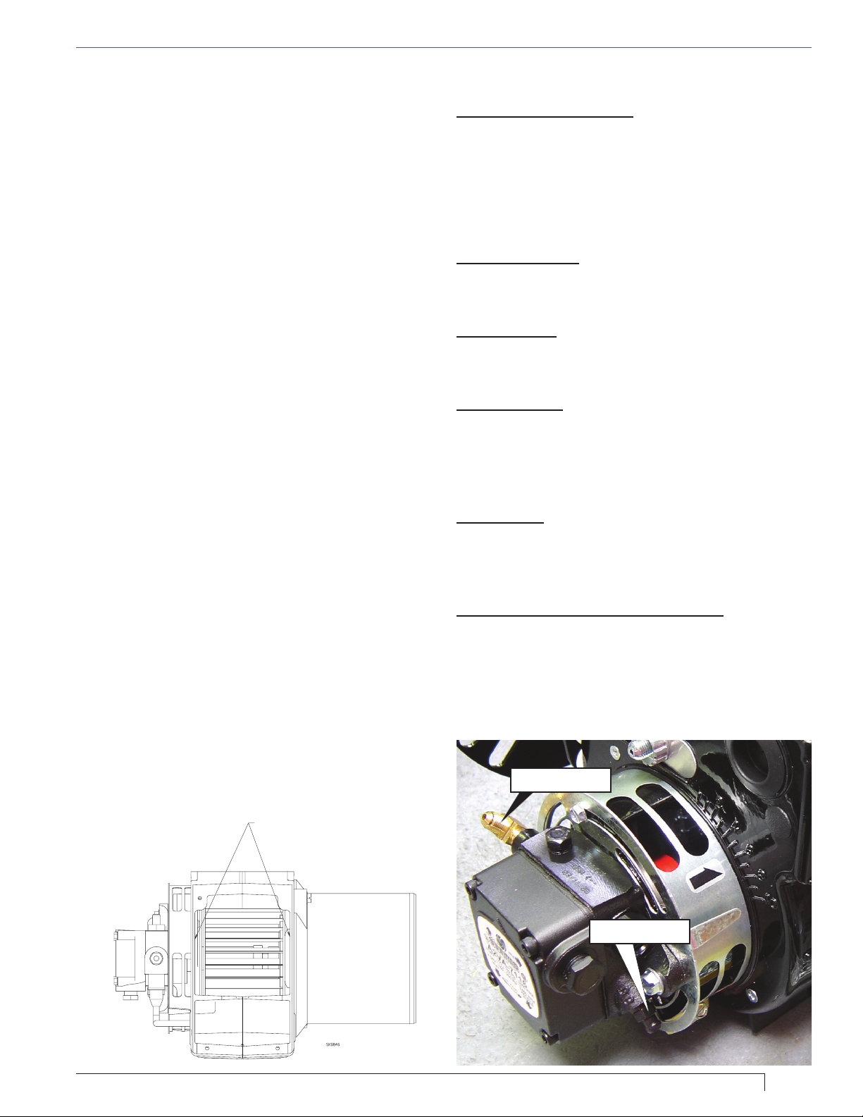
When replacing the blower wheel, verify the wheel
7.
is centered between the two sides of the burner
housing as shown.
Rotate the blower wheel until the set screw is
8.
centered on the fl at of the motor shaft. Tighten the
set screw to secure the wheel.
Slide the motor coupling on the motor shaft then
9.
install the motor on the burner housing. Insure that
the motor coupling fi ts between the motor shaft and
the pump shaft inside the housing. Tighten the motor
retaining screws. Reconnect the wires.
Restore power, start the burner and perform the
10.
combustion test described previously in this manual.
B. Pump Maintenance
General Pump Information
Important information - Long or oversized inlet lines may
require the pump to operate dry during initial bleeding period.
In such cases, the priming may be assisted by injecting fuel
oil in the pump gear set. Under lift conditions, lines and fi ttings
must be air tight. To assure this, “Pipe Dope” may be applied
to both the used and unused inlet and return fi ttings. Do NOT
use Tefl on tape or compression fi ttings.
Mounting Position
Beckett CleanCut pump may be mounted in any position
(except upside-down in a single pipe installation).
Vacuum Check
A Vacuum Gauge may be installed in either of the 1/4”
NPT inlet ports.
Pressure Check
Use the nozzle port when performing a pressure check.
If the bleed port is used, the reading on the gauge should
be approximately 5 psig higher than the pressure reading
on the nozzle port. See Figure 8.
Cutoff Check
To check cutoff pressure dead head a pressure gauge in the
nozzle port. Run the burner for a short period of time. Shut the
burner off. The pressure will drop and hold above zero.
Pressurized or gravity feed installations
These installations must not exceed 3 psig on inlet line or
return line at the pump per NFPA 31. A pressure greater
than 10 psig may cause damage to the shaft seal.
Figure 8. – Oil Supply Components
Nozzle Port
Figure 7. – Blower Wheel
24 Vdc SDC Burner Manual
CENTER WHEEL FOR EQUAL
DISTANCE FROM HOUSING SIDES
Bleed Port
9
Page 10
Section: Start Up Burner & Set Combustion
C. Solenoid Valve Testing
To check solenoid operation, perform the following.
1.
Check for oil fl ow and operating pressure by
removing the copper tubing from the nozzle line
and installing a pressure gauge in the line. With
the motor running and the coil energized, check the
gauge. The pressure should read 100 psig unless
otherwise stated.
2.
To check the solenoid valve cutoff function, deadhead
the pressure gauge onto the copper connector tube
attached to the nozzle port. Run the burner for a
short period of time. Shut the burner off. The solenoid
valve should close and the pressure should drop and
hold.
3.
Replace the solenoid valve if it does not pass the
previous steps.
Start Up Burner & Set
Combustion
Explosion and Fire Hazard
Failure to follow these instructions could
lead to equipment malfunction and result
in heavy smoke emission, soot-up, hot gas
puff-back, fi re and asphyxiation hazards.
Do not attempt to start the burner when excess oil has
y
accumulated in the appliance, the appliance is full of
vapor, or when the combustion chamber is very hot.
Do not attempt to re-establish fl ame with the burner
y
running if the fl ame becomes extinguished during
start-up, venting, or adjustment.
Vapor-Filled Appliance: Allow the unit to cool off
y
and all vapors to dissipate before attempting another
start.
Oil-Flooded Appliance: Shut off the electrical power
y
and the oil supply to the burner and then clear all
accumulated oil before continuing.
If the condition still appears unsafe, contact the Fire
y
Department. Carefully follow their directions.
y
Keep a fi re extinguisher nearby and ready for use.
A. Basic Burner Operation
With 7559 Primary Safety Control
The 7559 control provides the benefi ts of added safety,
convenience, and performance. It adds a valve on delay
and motor-off delay to the burner’s operation sequence that
promote clean burner operation. It has a lock-out function
that shuts the burner down if it is not operating properly. The
control adds fusing at the burner to protect against component
failures. The control also has redundant motor relays that are
checked for proper operation every heat cycle.
Variations to the burner circuits may occur due to optional
temperature, pressure, and vacuum switches that control
burner operation. Note that when external switches
are used to control motor operation they must be sized
correctly for the rated current or a relay should be installed
to isolate the switches from the motor’s full load current.
B. Combustion Set-up
As soon as burner motor starts rotating bleed all the air
from the pump. (Required with single-pipe systems.)
To bleed the pump, attach a clear plastic hose over the
vent fi tting. Loosen the fi tting and catch the oil in an empty
container. Tighten the fi tting when all air has been purged
from the supply system. Note: If the burner stops after a
fl ame is established, the unit probably requires additional
bleeding. Continue to bleed the system until the pump is
primed and a fl ame is established when the bleed valve
is closed.
C. Set Combustion with Instruments
Professional Service
Required
Incorrect installation, adjustment, and
use of this burner could result in severe
personal injury, death, or substantial
property damage from fi re, carbon
monoxide poisoning, soot or explosion.
Please read and understand the manual supplied with this
equipment. This equipment must be installed, adjusted
and put into operation only by a qualifi ed individual or
service agency that is:
y
Licensed or certifi ed to install and provide technical
service to oil heating systems.
y
Experienced with all applicable codes, standards and
ordinances.
y
Responsible for the correct installation and commission
of this equipment.
y
Skilled in the adjustment of oil burners using
combustion test instruments.
The installation must strictly comply with all applicable
codes, authorities having jurisdiction and the latest revision
of the National Fire Protection Association Standard for the
installation of Oil-burning Equipment, NFPA 31 (or CSAB139 and CSA-B140 in Canada). Regulation by these
authorities take precedence over the general instructions
provided in this installation manual.
10
Page 11

Section: Maintain & Service Burner
1.
Allow the burner to run for approximately 5 to 10
minutes.
2.
Follow these four steps to properly adjust the
burner:
Step 1: Adjust the air until a trace smoke level is
achieved.
Step 2: At the trace of smoke level, measure the
(or O2). This is the vital reference
CO
2
point for further adjustments.
Step 3: Increase the air to reduce CO2 by 1
percentage point (O2 will be increased by
approximately 1.4 percentage points).
Step 4: Recheck the smoke level. It should be zero.
This procedure provides a margin of reserve air to
3.
accommodate variable conditions.
Once the combustion level is set, tighten the fasteners
4.
on the air band and air shutter.
Start and stop the burner several times to ensure
5.
satisfactory operation.
Test the equipment safety controls to verify that
6.
they function according to the manufacturer’s
specifi cations.
Daily
Check the area around your burner/equipment to make
sure:
Nothing is blocking the burner inlet air openings.
○
Air ventilation openings are clean and unobstructed
○
and the exhaust is not crusted.
No combustible materials are stored near the
○
equipment.
There are no signs of oil or water leakage around
○
the burner or equipment.
C. Extended Down Time
If the equipment will be stored for an extended period of
time, ensure the fuel tank is full and add a fuel stabilizer
to the tank.
D. Regular Service/Maintenance
Use only Beckett replacement parts
for continued safe operation of the
burner.
Maintain & Service
Burner
A. Owner’s Information
Have your equipment inspected at regular intervals
by a qualifi ed service agency to assure continued
proper operation. The burner should be adjusted using
dedicated combustion test equipment. Failure to properly
set the burner could result in ineffi cient operation, and/or
conditions that could potentially cause severe personal
injury, death or substantial property damage.
B. Owner Service and Maintenance
Properly installed and maintained, your SDC burner will
provide years of effi cient, trouble-free operation. Please
take care of your equipment by following the warnings
provided and by immediately contacting your qualifi ed
service agency, if your burner is not operating properly.
This equipment should be serviced only by a qualifi ed
service agency. The appropriate test instruments must be
used.
Have your burner, serviced annually by your qualifi ed
service agency. The following components/assemblies
should be checked/adjusted/replaced on a regular basis.
Refer to the Replacement Parts exploded view for part
locations.
Replace the oil supply line fi lter, if applicable.
□
The line fi lter cartridge must be replaced to avoid
contamination of the pump and nozzle.
Inspect the oil supply system. All fi ttings should be
□
leak-tight. The supply lines should be free of water,
sludge and other restrictions.
Remove and clean the pump strainer.
□
□
Verify the nozzle is the one originally specifi ed by the
appliance manufacturer and replace the nozzle with
one having the exact specifi cations from the same
manufacturer.
□
Clean and inspect the electrodes for damage,
replacing any that are cracked or chipped.
□
Check electrode tip settings. Replace electrodes if
tips are rounded.
Inspect the igniter spring contacts. Clean or replace
□
if corroded.
Clean the cad cell, if applicable.
□
Make sure Low Firing Rate Baffl e is in place, if
□
required, for the burner application. Omitting the baffl e
can result in unacceptable burner combustion.
Inspect all gasket including the igniter base plate
□
gasket. Replace any that are damaged or missing.
24 Vdc SDC Burner Manual
11
Page 12

Section: Troubleshooting
Clean the blower wheel, air inlet, air guide, retention
□
head and static plate of any dirt, asphalt or other
material.
Check motor current. The amp draw should not
□
exceed the nameplate rating. Check all wiring for
loose connections or damaged insulation.
Check the pump pressure and cutoff function.
□
Check primary control safety lockout timing if
□
applicable. Refer to the information supplied by the
control manufacturer for procedures.
Check ignition system for proper operation.
□
□
Inspect the exhaust system for soot accumulation or
other restriction.
Clean the equipment thoroughly according to the
□
manufacturer’s recommendations.
Check the burner performance using test instruments.
□
It is good practice to make a record of the service
□
performed and the combustion test results.
Table 2. Nozzle Flow Rate by Size
Nozzle fl ow rate U. S. gallons per hour of No. 2 fuel
oil when pump pressure (psig) is:
Nozzle size
(rated at 100
psig)
100
psi
140
psi
1.75 1.75 2.07
2.00 2.00 2.37
2.25 2.25 2.66
2.50 2.50 2.96
2.75 2.75 3.24
3.00 3.00 3.55
3.50 3.50 4.13
4.00 4.00 4.70
4.50 4.50 5.30
Troubleshooting
Oil burners that are designed for use on road maintenance
equipment are built to take temperature extremes,
vibration, and rough handling. When performing the
following troubleshooting steps, we assume that the oil
burner motor and ignition transformer operate continuously
and the oil solenoid valve, which controls oil fl ow, is cycled
by the equipment controls. We also assume that there is
power to the burner and fuel in the tank.
In addition to typical mechanics tools, it is recommended
to have the following equipment on hand.
Meter capable of measuring volts, ohms and amps,
○
ignition transformer tester,
○
smoke pump tester,
○
combustion analyzer, and
○
0 to 200 psi pressure gauge.
○
See Table 3 on following page for troubleshooting steps.
5.00 5.00 -
12
Page 13

Table 3. Troubleshooting Chart
Symptom Possible Cause
If the burner is not igniting, the burner motor, drive coupling, and oil pump are operating and oil is
fl owing to the nozzle through the solenoid valve, check the following possibilities.
Check the air shutter adjustment. If the air shutter is opened too far, the fl ow of air may prevent the arc from
1.
Oil Not
Igniting
No Flame
reaching the oil spray. This may appear as a white vapor exhaust from the heater. [Refer to section “Start
up burner and set combustion”]
The ignition system may have failed to supply an adequate arc to ignite the oil. Check the battery and
2.
charging system to insure a continuous supply of 21.8 to 28 volts DC (15 amps). [Refer to section
“Nozzle Assembly Maintenance”]
Check the electrodes for wear and damage. Insure that the electrodes are adjusted properly. [Refer to
3.
section “Nozzle Assembly Maintenance”]
If there is no fl ame, the burner motor and igniter operate continuously and the oil solenoid valve is
functional, check the following possibilities.
Check for a plugged oil nozzle. [Refer to section 3]
1.
If the coil on the solenoid valve is actuating, insure that the valve is opening or closing properly. [Refer to
2.
section “Fuel Supply”]
3.
Check for suffi cient fuel pressure. Pressure is 100 psig with valve energized, unless otherwise noted.
[Refer to section “Drive Component Maintenance”]
Check the pump pressure. Check for air in fuel lines.
4.
Check burner for broken motor coupling. If the coupling is broken check pump rotation prior to replacing the
5.
coupling.
Check for contaminated fuel and/or partially plugged fuel fi lter. [Refer to section “Fuel Supply”]
6.
[Refer to section “Drive Component Maintenance”]
Section: Troubleshooting
Motor Not
Operating
No Oil Spray
Fluctuating
or No Pump
Pressure
If the blower motor is not operating, check the following possibilities.
Check voltage at the motor to insure that switches and relays, in line with the motor, are operating properly.
1.
[Refer to section “Burner Wiring”]
2.
Check pump and motor shaft operation. They should work freely without binding. [Refer to section “Drive
Component Maintenance”]
If the blower motor is operating, there is fuel in the tank, but oil does not spray out the end of the
nozzle, check the following possibilities.
Check for a broken or stripped coupling between the pump and the motor. [Refer to section “Drive
1.
Component Maintenance”]
Check the pump output for oil. [Refer to section “Drive Component Maintenance”]
2.
Check operation of the oil valve. [Refer to section “Drive Component Maintenance”]
3.
Check for a plugged nozzle. [Refer to section “Nozzle Assembly Maintenance”]
4.
Check for air in the oil line. [Refer to section “Nozzle Assembly Maintenance”]
5.
Check for fuel contamination or plugged fi lter. [Refer to section “Nozzle Assembly Maintenance”]
6.
If the pump pressure, as determined by a pressure gauge, is erratic or does not exist, check the
following possibilities.
Check motor rotational speed. Low rpm can cause erratic or no pump pressure. [Refer to section “Drive
1.
Component Maintenance”]
Check for a broken or worn motor coupling. [Refer to section “Drive Component Maintenance”]
2.
Check that the pump turns freely. [Refer to section “Drive Component Maintenance”]
3.
Check for air leaks in the lines. [Refer to section “Fuel Supply”]
4.
Check for oil froth at the bleed point. [Refer to section “Fuel Supply”]
5.
Check voltage at the motor. [Refer to section voltage rating on nameplate]
6.
Check for fuel contamination or partially plugged fi lter.
7.
If the blower motor is not operating at the rpm’s listed on the nameplate, check the following.
Slow Motor
Rotation
24 Vdc SDC Burner Manual
Check the supply voltage to the motor. [Refer to section voltage rating on nameplate]
1.
Check for free operation of the motor shaft and pump assembly. [Refer to section “Drive Component
2.
Maintenance”]
13
Page 14
Section: Replacement Parts
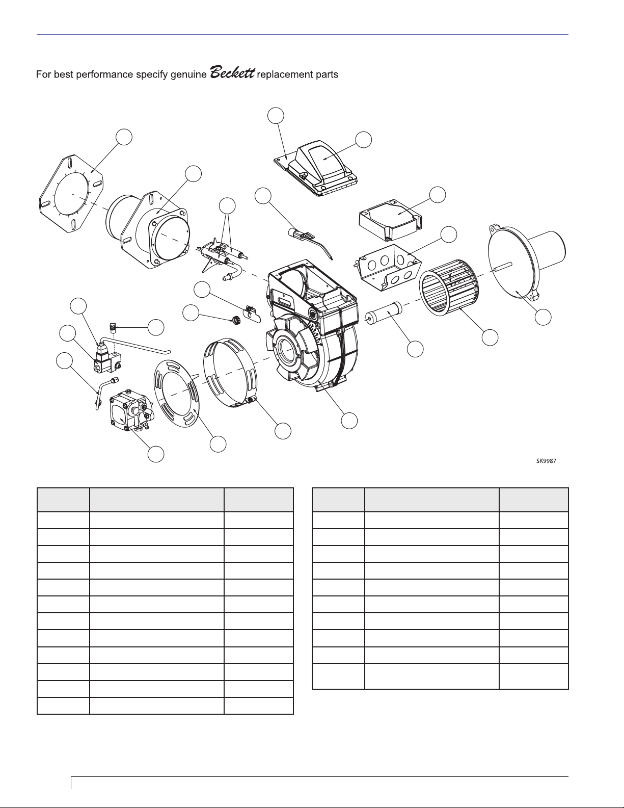
Replacement Parts
18
21
20
14
13
11
9
8
10
7
12
6
15
5
19
17
16
1
2
3
22
4
Illustration
#
Description Part#
1 DC Motor 22190U
2 Blower Wheel (6-1/4”) 2383U
3 Coupling 2154101
4 Burner Housing
5 Air Band, 10 slot 3819A
6 Air Shutter, 10 slot 3215
7 Pump Specify
8 Connector Tube Assembly 5394
9 Oil Valve 22246
10 Brass Elbow 2256
Illustration
#
13 Escutcheon Plate 3493
14 Electrode Kit over 3-5/8” 578731
15 Cad Cell Detector 7006U
16 4X4 Wiring Box 5770
17 Control Kit 7559X-XXXXU*
18
19 Igniter only 5218503U
20 Air Tube Assembly Specify
21 Flange Mounting Gasket Specify
Not Shown
11 Cord Set, Valve 21807
12 Splined Nut 3666
* ‘X’s indicate timing options. Contact Beckett for available part numbers.
14
Description Part#
Igniter Assembly With Base Plate
Tune-up Kit for 30 and 35 Air
Tube lengths
5218502U
578730
Page 15

24 Vdc SDC Burner Manual
15
Page 16

Limited Warranty Information
The R. W. BECKETT CORPORATION (“Beckett”) warrants to persons who purchase its “Products” from Beckett
for resale, or for incorporation into a product for resale (“Customers”), that its equipment is free from defects
in material and workmanship. To qualify for warranty benefi ts, products must be installed by a qualifi ed service
agency in full compliance with all codes and authorities having jurisdiction, and used within the tolerances of
Beckett’s defi ned product specifi cations.
To review the complete warranty policy and duration of coverage for a specifi c product, or obtain a written copy
of warranty form 61545, please choose one of the following options:
Visit our website at: www.beckettcorp.com/warranty
1.
Email your request to: [email protected]
2.
Write to: R. W. Beckett Corporation, P. O. Box 1289, Elyria, OH 44036
3.
NOTE: Beckett is not responsible for any labor cost for removal and replacement of equipment.
THIS WARRANTY IS LIMITED TO THE PRECISE TERMS SET FORTH ABOVE, AND PROVIDES EXCLUSIVE
REMEDIES EXPRESSLY IN LIEU OF ALL OTHER REMEDIES, AND IN PARTICULAR THERE SHALL BE
EXCLUDED THE IMPLIED WARRANTIES OF MERCHANTABILITY AND FITNESS FOR A PARTICULAR
PURPOSE. IN NO EVENT WILL BECKETT BE LIABLE FOR ANY INCIDENTAL OR CONSEQUENTIAL
DAMAGE OF ANY NATURE. Beckett neither assumes, nor authorizes any person to assume for Beckett,
any other liability or obligation in connection with the sale of this equipment. Beckett’s liability and Customer’s
exclusive remedy is limited to the cost of the product.
USA: P.O. Box 1289 ● Elyria, Ohio 44036
Canada: R.W. Beckett Canada, Ltd.
www.beckettcorp.com
●
Unit #3, 430 Laird Road ● Guelph, Ontario N1G 3X7
Part Number 6104 B24SDC R01, Printed in the U.S.A. 07/11
 Loading...