

Page 1
VHF-Transceiver
Family
AR6201-(X1X)
AR6201-(X2X)
RT6201-(X10)
RT6201-(X20)
RCU6201-(X1X)
AR6203-(X1X)
AR6203-(X2X)
Software Versions:
SCI1050S305 Version 3.07
SCI1051S305 Version 1.51
and upwards
AR6201
RCU6201
RT6201
AR6203
Becker Avionics GmbH ● Baden Airpark B108 ● 77836 Rheinmünster ● Germany
Telephone +49 (0) 7229 / 305-0 ● Fax +49 (0) 7229 / 305-217
http://www.becker-avionics.com ● e-mail: info@becker-avionics.de
Installation
Operation
Manual DV 14307.03
Issue 1 September 2013
Page 2

Page 3
FIRST ISSUE AND CHANGES
Issue 1 September 2013
LIST OF EFFECTIVE PAGES
Page No.: Date: Page No.: Date:
Cover Page
09/2013
I … VIII
09/2013
1-1 … 1-20 09/2013
2-1 … 2-66 09/2013
3-1 … 3-20 09/2013
DV 14307.03 / Article Number 0638.404-071
© 2013 by Becker Avionics GmbH / All rights reserved
Page 4

Page 5

AR6201 - RT6201 - RCU6201 - AR6203
Preface
Dear Customer,
Thank you for purchasing BECKER products.
We are pleased that you have chosen our product and we are confident
that it will meet your expectations.
AR620X-(XXX) VHF Transceivers are a modern family of communication
equipment that have comprehensive capabilities and significantly extend
the typical aeronautical transceivers.
Despite its small size and weight 620X- aircraft radio include inter
alia:
• Sensitive receiver which meets the most recent requirements of ED23C, including the ability to work in the offset-carrier (climax)
operation in 25 kHz and 8.33 kHz channel spacing (class H2).
• Receiver that includes SCAN (dual watch) mode. This allows
simultaneous monitoring of two different VHF frequency channels
without interrupting communication on the active frequency.
• High efficiency transmitter which delivers more than 10W modulated or
un-modulated output power at 28V supply voltage or 6W at 12V. Low
power consumption allows longer operation from battery.
• Extended built-in intercom which can work as:
o 4-way intercom with isolation mode – passengers could continue
conversation or listening to music from MP3 player at the same
time as pilots talk via intercom or communicate with the tower.
o 2-way intercom for tandem operation – pilot and co-pilot work
with separate controllers and can control their individual
audio parameters, like volume or VOX. This mode is preferred
especially for training due to full synchronization of LCD
contents.
• Non-volatile memory for storing:
o 99 VHF channels can manually be labeled for storage of VHF
channels
o 9 recently selected VHF channels are automatically stored
DV 14307.03 Issue 1 09/2013 Page I
Page 6

AR6201 - RT6201 - RCU6201 - AR6203
Table of Contents
List of Abbreviations VI
Section 1 GENERAL DESCRIPTION 1-1
1.1 Introduction 1-1
1.2 Purpose of Equipment 1-1
1.3 General Notes 1-2
1.4 Variants Overview 1-2
1.5 Short Description 1-3
1.5.1 AR6201 Single Block Transceiver 1-4
1.5.2 RT6201 Remote Transceiver 1-4
1.5.3 RCU6201 Remote Control Unit 1-5
1.5.4 AR6203 Single Block Transceiver 1-6
1.6 Features Overview 1-6
1.7 Technical Data 1-9
1.7.1 Power Supply Data 1-9
1.7.2 General Data 1-10
1.7.3 Dimensions & Weight 1-11
1.7.4 Receiver Data for AR620X and RT6201 1-11
1.7.5 Transmitter Data AR620X and RT6201 1-12
1.7.6 Emergency Operation 1-12
1.7.7 Software 1-13
1.7.8 Complex Hardware 1-13
1.7.9 Regulatory Compliance 1-13
1.8 Environmental Qualification AR620X and RCU6201 1-14
1.9 Environmental Qualification RT6201 1-16
1.10 Accessories 1-18
Page II DV 14307.03 Issue 1 09/2013
Page 7

AR6201 - RT6201 - RCU6201 - AR6203
Section 2 INSTALLATION 2-1
2.1 Limitations 2-1
2.2 Unpacking the Equipment and Preparation for
Installation 2-1
2.3 Mechanical Installation 2-1
2.3.1 AR6201 and RCU6201 Installation 2-1
2.3.2 AR6203 Installation 2-3
2.3.3 RT6201 Installation 2-5
2.4 Electrical Interface 2-8
2.4.1 Connectors and Pin Assignment for AR6201, AR6203
and RT6201 2-8
2.4.2 Inputs / Outputs Detailed Description 2-11
2.4.3 Connector and Pin Assignment for RCU6201 2-16
2.5 Installation and Configuration of 620X Transceivers 2-17
2.6 Antenna Installation 2-18
2.7 Installation Setup for RT/AR6201-(X1X) 2-19
2.7.1 Entering Installation Setup 2-19
2.7.2 Leaving Installation Setup 2-19
2.7.3 Page Up / Page Down in the Installation Setup 2-19
2.7.4 Storage of Setup Data 2-19
2.7.5 Terminate Installation Setup 2-19
2.7.6 VU Meter 2-20
2.7.7 Installation Setup Pages - Data Description 2-20
2.8 Factory Default Settings 2-35
2.9 Typical Installations with Recommended Settings and
Wiring Diagrams 2-37
2.9.1 Single Seat Glider 2-37
2.9.2 Twin Seat Motor Glider 2-40
2.9.3 General Aviation (GA) Aircraft using Standard
Microphones 2-42
2.9.4 Installation Setup for individual dual headset
configuration (two IC circuit) 2-44
DV 14307.03 Issue 1 09/2013 Page III
Page 8

AR6201 - RT6201 - RCU6201 - AR6203
2.9.5 Installation Setup for Twin Seat with AR6201 Tandem
Configuration 2-46
2.9.6 Wiring for Aircraft with Four Seats (no TANDEM) 2-48
2.9.7 Installation with RT6201 2-51
2.9.8 Aircraft with Intercom System 2-52
2.9.9 Installation Setup for Twin Seat with RT6201 Tandem
Configuration 2-55
2.10 Retrofitting an AR4201 with an AR620X 2-57
2.10.1 Pin Compatibility 2-57
2.10.2 Dynamic Microphone Input 2-59
2.10.3 Temperature Sensor 2-59
2.10.4 RS-232 Interface 2-59
2.10.5 AFCU/AGC/AFWB 2-60
2.10.6 CPIN 2-60
2.10.7 +13.75V Switched 2-60
2.10.8 PWR_EVAL 2-60
2.11 Post Installation Tests 2-60
2.11.1 Mechanical Installation and Wiring Check 2-60
2.11.2 Power Supply 2-60
2.11.3 Receiver / Transmitter Operation 2-61
2.11.4 Antenna Check 2-61
2.11.5 Interference Check 2-61
2.11.6 Flight Test Check 2-63
2.12 Trouble Shooting 2-63
2.13 Continued Airworthiness 2-65
Page IV DV 14307.03 Issue 1 09/2013
Page 9

AR6201 - RT6201 - RCU6201 - AR6203
Section 3 OPERATION 3-1
3.1 Safety Instructions 3-1
3.2 Controls and Indicators 3-2
3.2.1 Controls 3-2
3.2.2 Symbols Shown on the Display 3-3
3.3 Start-Up 3-3
3.4 Receive and Transmit Mode 3-4
3.4.1 Receive Mode 3-4
3.4.2 Transmit Mode 3-4
3.5 Frequency Selection Modes 3-5
3.5.1 Standard Mode 3-5
3.5.2 Direct Tune Mode 3-6
3.5.3 Channel Mode 3-7
3.5.4 Scan Mode 3-9
3.6 Squelch 3-10
3.7 RX Field Strength Indication 3-10
3.8 Channel Spacing Mode 3-11
3.9 Storage Function 3-11
3.9.1 Manual Storage Function 3-11
3.9.2 Automatic Storage Function 3-13
3.10 Auxiliary Audio Input 3-13
3.11 Intercom Operation 3-13
3.12 VOX & Speaker Operation 3-15
3.13 Menus 3-15
3.13.1 Intercom Menu 3-15
3.13.2 Pilots Menu 3-17
3.14 Warning and Failure Indications 3-18
DV 14307.03 Issue 1 09/2013 Page V
Page 10

AR6201 - RT6201 - RCU6201 - AR6203
List of Abbreviations
AC ..... Alternating Current
AF ..... Audio Frequency
AR ..... Airborne Radio
ATT .... Attenuation
AUX .... Auxiliary
AWG .... American Wire Gauge
BNC .... Bayonet Neill Concelman
CBIT ... Continuous Built-In Test
CFG .... Configuration
CH ..... Channel
CM ..... Chassis Module
COM .... Communication
DC ..... Direct Current
EASA ... European Aviation Safety Agency
EMI .... Electro Magnetic Interference
ETSO ... European Transmission System Operators
GND .... Ground (Aircraft Ground)
GPS .... Global Positioning System
HMI .... Human Machinery Interface
HIRF ... High Intensity Radiated Fields
IC ..... Intercom
I&O .... Installation & Operation
LCD .... Liquid Crystal Display
MFD .... Multi-Function Display
M&R .... Maintenance & Repair
N/A .... Not Applicable
NAV .... Navigation
PBIT ... Power-On Built In Test
PTT .... Push To Talk
PWR .... Power
RCU .... Remote control unit
Page VI DV 14307.03 Issue 1 09/2013
Page 11

AR6201 - RT6201 - RCU6201 - AR6203
RSSI ... Received Signal Strings Indication
RT ..... Remote Transceiver
RX ..... Receive
SQL .... Squelch
SPKR ... Speaker (Loudspeaker)
SRC .... Source
SW ..... Software
TSO .... Technical Standard Order
TX ..... Transmit
VOX .... Voice Operated IC Threshold
VHF .... Very High Frequency
VDC .... Voltage Direct Current
VSWR ... Voltage Standing Wave Ratio
VU ..... Volume Unit
Units
V ...... Volt
mV ..... Millivolt
A ...... Ampere
mA ..... Milliampere
W ...... Watt
mW ..... Milliwatt
kHz .... Kilohertz
MHz .... Megahertz
s ..... Second
dBm .... Power ratio in decibels
dB ..... Decibel
Ohm(Ω) . Resistor
kg ..... Kilogram
t ...... Tons
°C ..... Degree Celsius
mm ..... Millimeter
cm ..... Centimeter
DV 14307.03 Issue 1 09/2013 Page VII
Page 12

AR6201 - RT6201 - RCU6201 - AR6203
Blank
Page VIII DV 14307.03 Issue 1 09/2013
Page 13
AR6201 - RT6201 - RCU6201 - AR6203
Section 1 GENERAL DESCRIPTION
1.1 Introduction This manual describes the operation and installation of the
RCU/RT/AR6201 VHF Transceiver Family equipment. The ID label on your
device shows the part number for identification purposes.
Before starting to operate the unit(s) please rea d this manual carefully
with particular attention to the description referring to your
device(s). This manual also contains several optional elements of the
system (second controller for example), that may not be contained in
your delivery package and in that case are not applicable.
For simplification of this document the short version “620X” for VHF
transceivers and “RCU6201” for the remote controllers will be used
instead of the full part number identification.
The manuals DV 14307.03 I&O (“Installation and Operation”) and DV
14307.04
M&R (“Maintenance and Repair”) contain the following sections:
Section
1 General
2 Installation
3 Operation
4 Theory of Operation
5 Maintenance and Repair
6 Illustrated Parts List
7 Modification and Changes
8 Circuit Diagrams
DV 14307.03
I&O
X X
X X
X X
N/A X
N/A X
N/A X
N/A X
N/A X
DV 14307.04
M&R
1.2 Purpose of Equipment The 620X transceivers enable voice communication between aircrafts or
between aircraft and ground using the very high frequency band between
118.000 to 136.9916 MHz respectiv ely 136.9750 with a selectable c hannel
spacing of 25 kHz respectively 8.33 kHz. The wide scope of accessories
also allows usage of the 620X VHF transceivers in ground-based
applications.
DV 14307.03 Issue 1 09/2013 Page 1-1
Page 14

Part Number
Article No
8.33kHz Mode
Transmit PWR
AR6201 - RT6201 - RCU6201 - AR6203
The 620X-(XXX) Transceiver Family is dedicated to applicatio ns where low
power consumption is required. They are capable to operate from standar d
14 VDC and 28 VDC installations and from 12 VDC or 24 VDC batteries.
Ultra low power consumption with extrem ely wide DC supply voltage range
as well as compact and lightweight desig n allows application for glider s
and leisure aircraft up to 2000 kg and balloons.
Built-in 4-seat configurable intercom, transmitter output power up to
10W and option for connection of two controllers in tandem
configurations extends the flexibility of 620X VHF transceivers.
The 620X transceivers also provide additional options such as:
• Intercom functional ity for voice commun ication between aircraft crew
and passengers
• Squelch functionali ty that automaticall y mutes receiver audio signal
until clear signal is received to avoid unwanted audio noise
• Scan functionality for simultaneous monitoring of two VHF channels
(receive mode)
• AUX audio input for connection of additional audio devices like
navigation receiver, warning tone generator or MP3 music player.
• VHF channel database for easy access to predefined frequency channels
• Tandem functionality for synchronized operation of two controllers
1.3 General Notes In this document the word “frequency” is also used in the sense of
“channel name”, as defined in EUROCAE, ED-23B: chapter 1.3.2.
In this document the word “memory channel” or “channel” means a memory
place identified by a channel number, where a frequency may be stored
for later use.
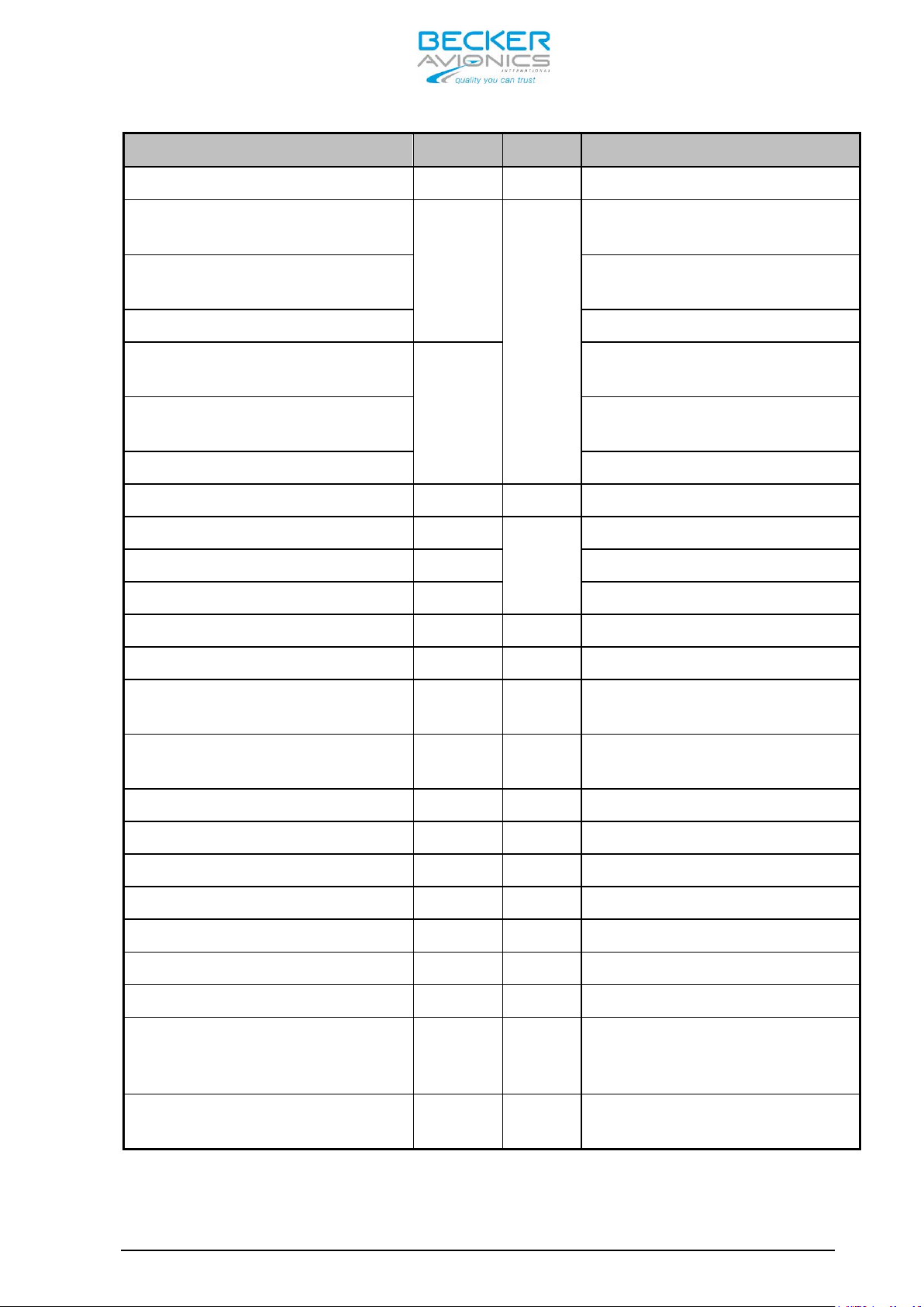
1.4 Variants Overview Within the part number, the meaning of “- (XXX)” is:
(0XX) indicates 8.33/25 kHz channel spacing capability
(1XX) indicates only 25 kHz channel spacing capability
(X1X) indicates transmit power 10W at 28V
(X2X) indicates transmit power 6W at 12V
(XX2) indicates white illumination color on a black panel
AR6201 Single Block Transceiver (refer to Figure 1-1)
Page 1-2 DV 14307.03 Issue 1 09/2013
AR6201-(012) 0631.418-910 yes 10W at 28V
AR6201-(112) 0631.434-910 no 10W at 28V
Page 15
Part Number
Article No
8.33kHz Mode
Transmit PWR
Part Number
Article No
8.33kHz Mode
Transmit PWR
Part Number
Article No
8.33kHz Mode
Transmit PWR
Part Number
Article No
8.33kHz Mode
Transmit PWR
AR6201 - RT6201 - RCU6201 - AR6203
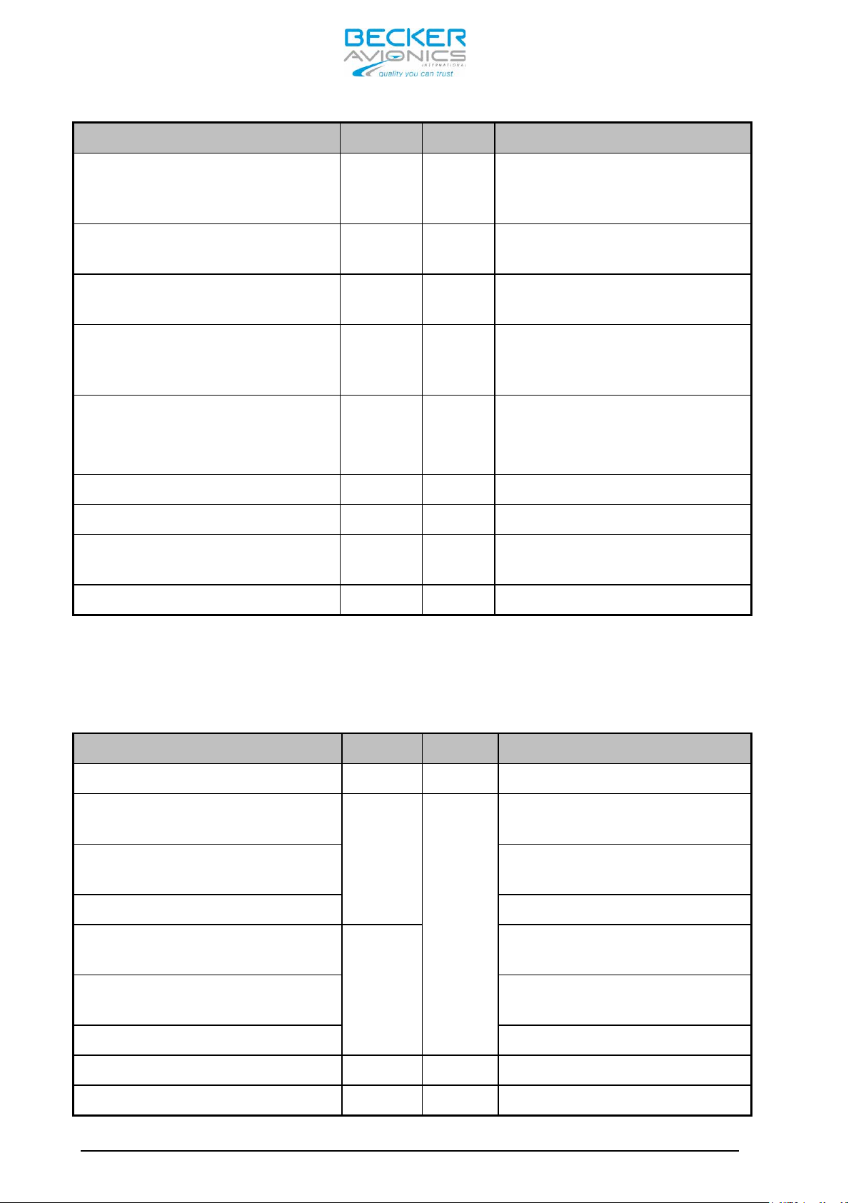
AR6201-(022) 0636.339-910 yes 6W at 12V
AR6201-(122) 0636.355-910 no 6W at 12V
RT6201 Remote Transceiver (refer to Figure 1-2)
RT6201-(010) 0631.442-910 yes 10W at 28V
RT6201-(020) 0636.312-910 yes 6W at 12V
RT6201–(110) 0638.609-910 yes 10W at 28V
RT6201-(120) 0638.617-910 yes 6W at 12V
RCU6201 Remote Control Unit (refer to Figure 1-3)
RCU6201-(012) 0631.469-910
RCU6201-(112) 0631.485-910
yes
no
AR6203 Single Block Transceiver (refer to Figure 1-4)
AR6203-(012) 0630.993-910 yes 10W at 28V
AR6203-(112) 0631.566-910 no 10W at 28V
AR6203-(022) 0636.371-910 yes 6W at 12V
AR6203-(122) 0636.398-910 no 6W at 12V
1.5 Short Description
For Single Configuration the Following Combinations apply:
• AR6201 or AR6203 Single Block Transceiver
• RT6201 Remote VHF Transceiver with controller RCU6201
N/A
N/A
For Tandem Configuration the Following Combinations apply:
DV 14307.03 Issue 1 09/2013 Page 1-3
• AR6201 or AR6203 S ingle Block Transceiver with additional controller
RCU6201
• RT6201 Remote VHF Transceiver wi th controller RCU6201 and additional
second controller RCU6201
In tandem configuration two controllers and one transceiver are
connected. Tandem configuration is useful for training purposes where
Page 16
AR6201 - RT6201 - RCU6201 - AR6203
pilot and student have their own controller with full-synchr onized views
or as separate controllers for pilot and co-pilot.
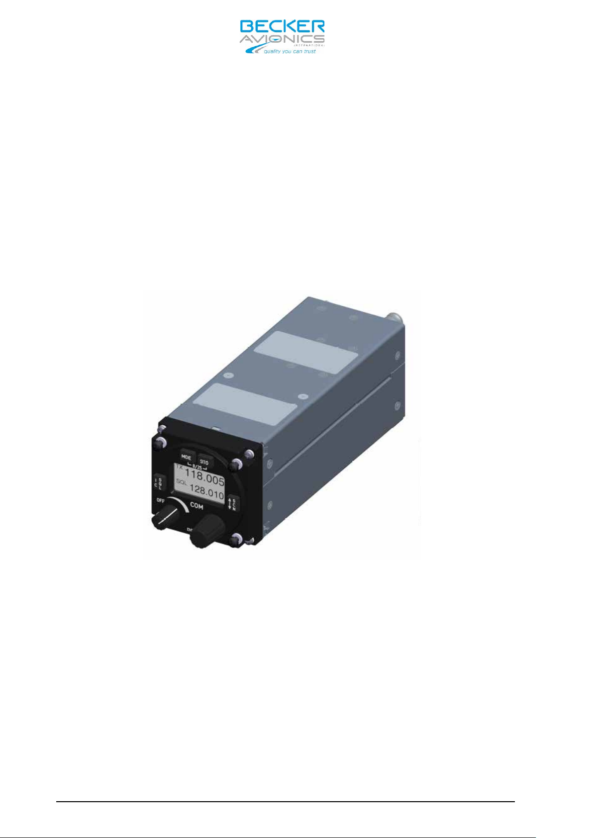
1.5.1 AR6201 Single Block Transceiver The AR6201 Single Block Transceiver is a compact and lightweight unit
designed for operation in a cockpit environment for both general
aviation aircraft and helicopters. The dimensions correspond to the
standard instrument diameter of 58 mm (2 ¼ inch). All controls and
indicators are located on the front panel.
The equipment connectors and the a ntenna socket are located at the rear
of the units.
The AR6201 should be mounted by means of four screws (rear panel
installation).
Figure 1-1: AR6201 Single Blo ck Transceiver; 58 mm (2 ¼ inch)
standard instrument cut-out
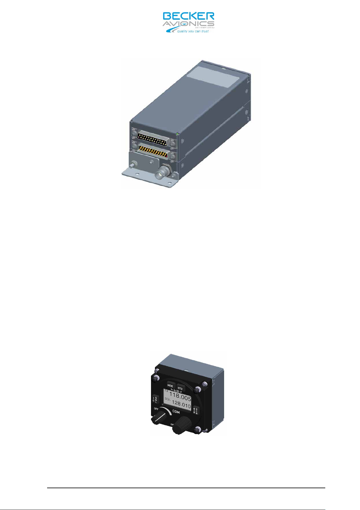
1.5.2 RT6201 Remote Transceiver The RT6201 Remote Transceiver is a compact and lightweight single block
unit in rectangular shape that contains a VHF transceiver. The
dimensions correspond to the stand ard instrument diameter of 58 mm (2 ¼
inch).
The RT6201 Remote Transceiver can be controlled via its dedicated
controller RCU6201 or by a third party controller via MFD (BECKER
proprietary protocol required).
Page 1-4 DV 14307.03 Issue 1 09/2013
Page 17
AR6201 - RT6201 - RCU6201 - AR6203
Figure 1-2: RT6201 Remote Single Block VHF transceiver,
back panel installation
The RT6201 Remote Transceiver is installed by means of the attached
mounting provisions and four screws (back panel installation).
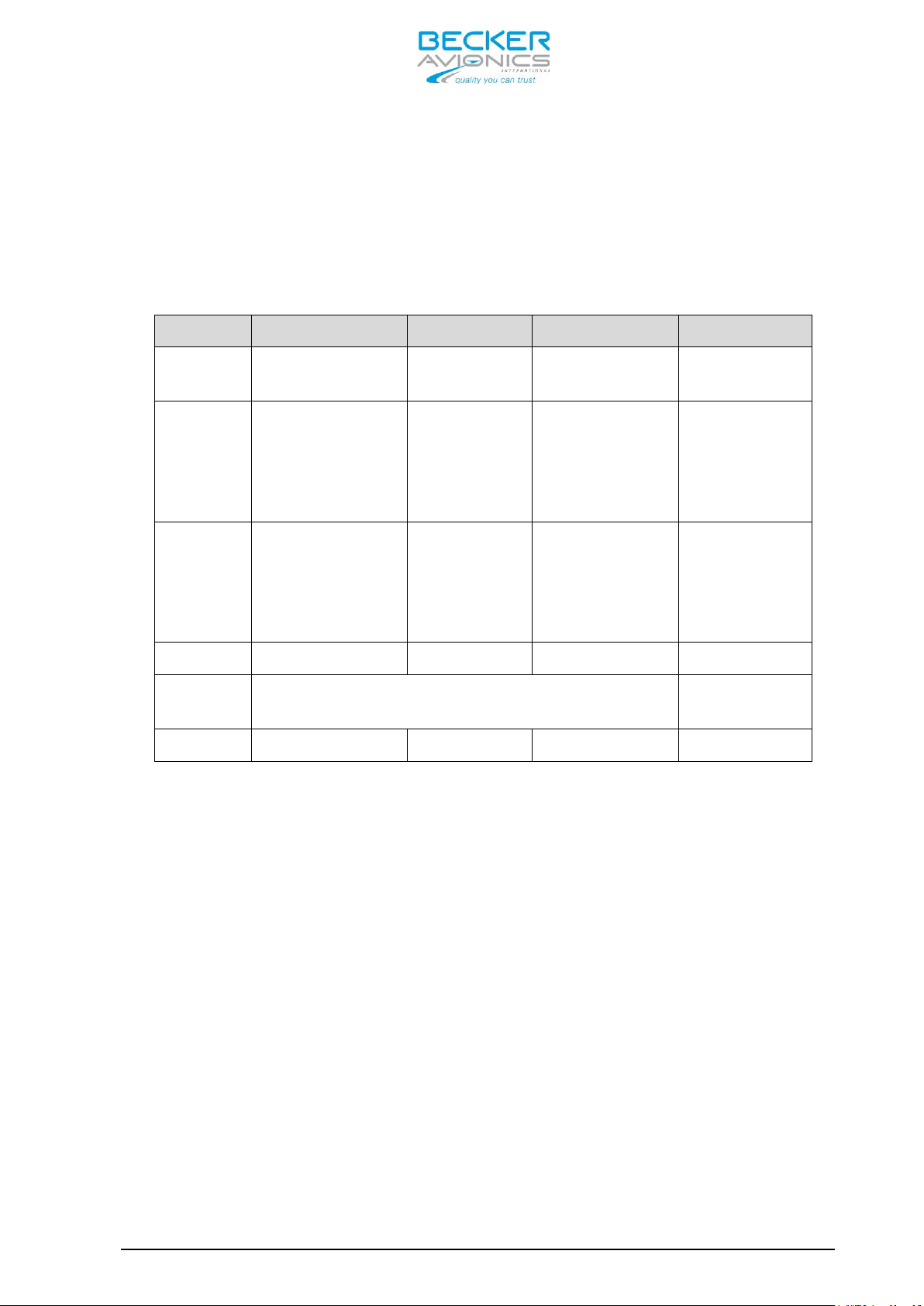
1.5.3 RCU6201 Remote Control Unit The RCU6201 Remote Control Unit is a compact and lightweight unit. The
dimensions correspond to the stand ard instrument diameter of 58 mm (2 ¼
inch).
All controls and indicators are located on the front panel. The
equipment connectors are located at the rear of the units.
The controller RCU6201 should be mounted with four screws (rear panel
installation).
Figure 1-3: RCU6201 Remote Control Unit; 58 mm (2 ¼ inch)
standard instrument cut-out
DV 14307.03 Issue 1 09/2013 Page 1-5
Page 18

AR6201 - RT6201 - RCU6201 - AR6203
1.5.4 AR6203 Single Block Transceiver The AR6203 Single Block Transceiver is designed as a single block unit.
AR6203 is designed for operation in a cockpit environment for both
general aviation aircraft and helicopters. The dimensions correspond to
state-of-the-art 160mm (6.3 “) panel mounted design.
the
Figure 1-4: AR6203 Single Block Transceiver
All control elements are located on the front panel of the unit. For
connection to the aircraft inter-wiring two 25-pin unit connectors and
BNC antenna socket are located at the rear of the unit.
The AR6203 should be mounted with the designated mounting kit MK6403-1
(refer to chapter 1.10). Six holes on both sides of the mounting kit
frame enable the device to be mounted in the aircraft cockpit.
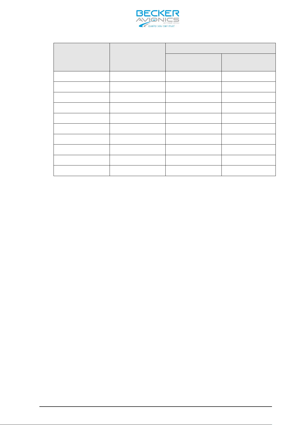
1.6 Features Overview
Frequency Indication
A liquid crystal display (LCD) provides the frequency indication. The
required operating frequency is set with the rotary knob. The relation
between the real operating frequency and the displayed frequency is
according to standards (ED-23B, chapter 1.3.2). For an overview, refer
to the table below.
Page 1-6 DV 14307.03 Issue 1 09/2013
Page 19
Operating
Frequency
(MHz)
Channel
Spacing
(kHz)
Displayed Frequency
8.33 + 25 kHz
mixed Mode
25 kHz only
Mode
AR6201 - RT6201 - RCU6201 - AR6203
118.0000 25 118.000 118.00
118.0000 8.33 118.005 N/A
118.0083 8.33 118.010 N/A
118.0166 8.33 118.015 N/A
118.0250 25 118.025 118.02
etc. etc. etc. etc.
136.9750 25 136.975 136.97
136.9750 8.33 136.980 N/A
136.9833 8.33 136.985 N/A
136.9916 8.33 136.990 N/A
Audio Outputs
The 620X VHF Transceiver includes four fully configurable outputs:
• Headphone 1 output, rated output power is 300 mW into 75 Ohm.
• Headphone 2 output, rated output power is 200 mW into 75 Ohm.
• Speaker output, rated output power is 4 W into 4 Ohm.
• LINE-OUT output intended for ground station use only
Note: Headphone 2 and speaker output cannot be active at the same time
Mike Inputs
The VHF transceiver has an input for dynamic microphone (DYN_MIKE) and
an input for standard microphone (STD_MIKE).
The 620X VHF Transceiver provides four microphone inputs:
• standard microphone input 1 (STD_MIKE1)
• standard microphone input 2 (STD_MIKE2)
• standard microphone input 3 (STD_MIKE3)
• dynamic microphone input (DYN_MIKE)
Each input is able to operate with one single microphone or with two
microphones of the same type connected in parallel.
AF Auxiliary Input
The AF auxiliary provides the interface to connect an external audio
source (e.g. NAV, music-player) to the transceiver. Interconnection of
multiple external audio sources on this particular port requires
DV 14307.03 Issue 1 09/2013 Page 1-7
Page 20

AR6201 - RT6201 - RCU6201 - AR6203
additional external decupling/isolation resistors. The external audio is
audible only when the transceiver is in receive mode.
The individual audio volume is set directly at the particular external
equipment.
Sidetone
The sidetone is available on the headphone output during transmission.
The sidetone volume automatically adapts to the intercom volume setting.
Squelch Operation
When enabled the squelch (muting) circuit suppresses weak si gnals. There
are two kinds of squelch methods implem ented: carrier squelch and noise
squelch. The carrier squelch depends on received signal strength and is
adjustable in the installation setup; the noise squelch depends on
detected noise level and is adjustable in the pilot setup.
Memory Channels
The memory function allows storage of up to 99+9 frequencies. This
memory may contain up to 99 frequencies stored manually or programmed
from PC that can be labeled with VHF channel numbers or assigned text
label. Additionally the last recently used (active) 9 frequencies are
stored automatically as “LAST” channels. A user defined text label can
also be assigned for each stored frequency.
Intercom Operation
Aircraft internal communication via connected headsets is provided by
the built-in intercom circuit. The 620X has two intercom circuits:
“Front row” and “Back row”. A maximum of four headsets can be connected
(for example pilot & copilot on first circuit and two passengers on
second circuit).
Scan Mode
In scan mode a dual watch function is provided. T he device is capable of
monitoring frequencies on two channels, active & preset simultaneously.
The signal of the active frequenc y will always b e audible, since it will
have priority at all times.
Tandem operation
Tandem mode enables operation of two controllers simultaneously. The
controllers are synchronized, so that both display the same information
Illumination
The illumination of LCD and push buttons can be controlled either
directly from the front panel via the pilots menu or externally via the
dimming input lines. If the external dimming is selected, the
Page 1-8 DV 14307.03 Issue 1 09/2013
Page 21

AR6201 - RT6201 - RCU6201 - AR6203
illumination curve (brightness to voltage relation) can be adjusted in
the installation setup.
LOW BATT Indication
The VHF transceiver monitors power suppl y voltage. If the supply voltag e
drops below the adjustable threshold, the display indicates the message
“LOW BATT”. If the power supply voltage drops further, emergency
operation mode is entered.
Emergency Operation
If the power supply voltage drops below 10.25 V, the VHF transceiver
continues operation with degraded perf ormance. In case the power supply
drops below 9.0V the unit is automatically switched off.
Built-in Tests PBIT and CBIT
After power-up, the unit performs a se lf-test (power-up built-in test /
PBIT). During PBIT the transceiver displays “WAIT” and the correspo nding
software versions of both the control head and chassis module.
If faults are detected during PBIT, the error message “FAILURE press an y
key” is displayed. If no faults are detected the transceiver
automatically activates the mode set before last power-off.
During normal operation a continuous built-in test (CBIT) permanently
verifies the correct operation of the unit. If a problem is detected
during CBIT, an error message will be displayed.
Installation Setup
Configuration of the installation parameters such as mike sensitivity,
mike type selection, speaker enable/disable plus other parameters are
available via the installation setup.
Service Mode
The service mode is a special configuration mode accessible via RS422
interface with a proprietary serial data communication protocol. This
mode is for use by authorized maintena nce organizations during aircraft
service on ground only.
1.7 Technical Data
1.7.1 Power Supply Data For 620X units the following data applies:
Nominal supply voltage range .... 11.0 … 30.3 V
extended supply voltage range ... 10.25 V … 32.2V
Emergency operation ............. 9.0 V to 10.25 V
Dimming control ................. 0…14 V or 0…28 V
DV 14307.03 Issue 1 09/2013 Page 1-9
Page 22

6W
10W
6W
10W
1.8A at
1.5A at
1.8A at
1.5A at
1.2A at
1.0A at
1.2A at
1.0A at
A at
1.0A at
AR6201 - RT6201 - RCU6201 - AR6203
Typical Power Consumption
Power “off” @ 12 VDC
Power “off” @ 27.5 VDC
Reception stand-by mode
@ 13.75 VDC, panel backlight
off
Reception stand-by mode
@ 27,5 VDC, panel backlight
off
Transmit mode
@ 13,75 VDC, VSWR=1:1
AR620X
(X2X)
≤ 0.10
mA
≤ 0.10
mA
≤ 140 mA ≤ 140 mA ≤ 120 mA ≤ 120 mA ≤ 20 mA
≤ 80 mA ≤ 80 mA ≤ 80 mA ≤ 80 mA ≤ 20 mA
70%
0%
AR620X
(X1X)
≤ 0.10
mA
≤ 0.10
mA
-
RT6201
(X2X)
≤ 0.10
mA
≤ 0.10
mA
70%
0%
RT6201
(X1X)
≤ 0.10
mA
≤ 0.10
mA
- ≤ 20 mA
RCU6201
≤ 0.10
≤ 0.10
(XXX)
mA
mA
1.4A at
Transmit mode
@ 27.5 VDC, VSWR=1:1
Absolute maximum current
@ 13.75 VDC, VSWR=3:1
Absolute maximum current
@ 27.5 VDC, VSWR=3:1
1.7.2 General Data For 620X units the following data apply:
Frequency range ............... 118.000 MHz to 136.975 MHz (-1XX model)
118.000 MHz to 136.9916 MHz (-0XX model)
Channel spacing ............... 25 kHz (-1XX model)
8.33/25 kHz (-0XX model)
Number of channels ............ 760 (-1XX model)
70%
0%
≤ 3A - ≤ 2,9A -
≤ 2A ≤ 2.5A ≤ 1.9A ≤ 2.4A
70%
1.0A at
0%
70%
0%
1.4
70%
0%
≤ 20 mA
≤ 20 mA
≤ 20 mA
2280 + 760 (-0XX model)
Page 1-10 DV 14307.03 Issue 1 09/2013
Page 23
158.8mm
(front plate
Mounting Kit
AR6201 - RT6201 - RCU6201 - AR6203
Storage Temperature range ... -55°C to +85°C
Operating Temperature range .. -20°C to +55°C AR620X-(XXX) and RCU6201-(XXX)
-40°C to +55°C RT6201-(XXX)
short-time +70°C (all versions)
Operating Altitude ........... 35,000 ft
Vibration ................... Category S (Curve M) + Category U (Curve G)
1.7.3 Dimensions & Weight AR6201-(XXX) AR6203-(XXX) RCU6201-(XXX) RT6201-(XXX) Front
panel
Depth of
unit
Mounting
Material AlMg AlMg/Plastic AlMg AlMg
Surface
treatment
Weight 675g 850g 150g 600g
1.7.4 Receiver Data for AR620X and RT6201
61.2mm
x 61.2 mm
187.8 mm
(front plate to
end of antenna
connector)
(back panel)
standard
58 mm diameter
(2¼ inch)
Control-head coated with black matt paint
x 41.2 mm
207 mm
to end of
antenna
connector)
MK6403-1
61.2 mm
x 61.2 mm
39.3 mm 188 mm
(back panel)
standard
58 mm diameter
(2¼ inch)
61 mm
x 61 mm
Mounting Kit
MK6201-(010)
or directly
on avionic
bay
Sensitivity ..................... ≤ -101 dBm for a (S+N)/N ratio of 6 dB
(nominal)
................................ ≤ -93 dBm for a (S+N)/N ratio of 6 dB
(qualified under environmental conditions)
Effective bandwidth ............. ≥ ± 2.78 kHz at the 6 dB points
(8.33 kHz channel spacing) ≤ ± 7.37 kHz at the 60 dB points
Effective bandwidth ............. ≥ ± 8 kHz at the 6 dB points
(25 kHz channel spacing) ≤ ± 22 kHz at the 60 dB points
Squelch ........................ level adjustable
AGC characteristic .............. ≤ 6 dB in range -93 dBm to 0 dBm
Distortion ...................... ≤ 15% at 30% 10dB below rated output power
≤ 15% at 70% and rated output power
Audio frequency response ........ ≤ 6 dB 350 Hz to 2500 Hz
(8.33 kHz channel spacing) ≥ 35 dB at 4000 Hz
Audio Noise ..................... ≤ 6 dB 300 Hz to 3400 Hz
≥ 18 dB at 4000 Hz
DV 14307.03 Issue 1 09/2013 Page 1-11
Page 24

AR6201 - RT6201 - RCU6201 - AR6203
Rated output for speaker operation .. ≥ 4 W into 4 Ohm
Rated output power for headphone 1 .. ≥ 300 mW into 75 Ohm
≥ 100 mW into 600 Ohm
Rated output power for headphone 2 .. ≥ 200 mW into 75 Ohm
≥ 100 mW into 600 Ohm
Audio auxiliary input ............... 50 mV to 8 V (adjustable) across 600 Ohm
Offset-carrier operation ........... YES (25 / 8.33 kHz)
1.7.5 Transmitter Data AR620X and RT6201
Output power into 50 Ohm ....... ≥ 6 W for AR620X-(X2X) and RT6201-(X2X)
(with and without modulation): . ≥ 10 W for AR620X-(X1X) and RT6201-(X1X)
Frequency tolerance ............. ≤ ±5 ppm
Duty cycle ...................... 120 sec (TX): 480 sec (RX)
Type of modulation .............. A3E
Modulation capability ........... ≥ 70%
Distortion ...................... ≤ 15%
Audio frequency response ........ ≤ 6 dB, 350 Hz to 2500 Hz
(8.33 kHz channel spacing)
Audio frequency response ........ ≤ 6 dB, 300 Hz to 2500 Hz
(25 kHz channel spacing)
Dynamic microphone .............. 1…20 mV compressor starting point,
adjustable
(with compressor) Input balanced, 200 Ω
Input range up to 20 dB above compressor
starting point.
Standard microphone(s) .......... 10…1000 mV compressor starting point,
adjustable
(with compressor) Input unbalanced, 150Ω
Input range up to 20 dB above compressor
starting point.
FM deviation with modulation .... ≤ 3 kHz
Sidetone ........................ Adjustable
Automatic shutdown of transmit mode 120 sec.
(Factory configurable 30 sec … 120 sec)
1.7.6 Emergency Operation If the device enters emergency operation, the speaker is switched “OFF” due to degraded performance. Depending on settings in installation setup “LOW BATT” may be indicated if supply voltage drops below a predefined threshold to indicate to the user, that he should connect his headset as the speaker may be switched “OFF” soon).In this case, a headset is
Page 1-12 DV 14307.03 Issue 1 09/2013
Page 25

AR6201 - RT6201 - RCU6201 - AR6203
required to continue operation of the transceiver. This data is
applicable for AR620X and RCU6201.
Panel & Display Backlight ...... switched off for
TX Output Power ................. ≥ 2 W into 50 Ω (with modulation)
TX Modulation Depth ............. ≥ 50 %
RX Sensitivity .................. ≤-93 dBm for a (S+N)/N ratio of 6 dB
CAUTION: For power-supply voltages below 10.25 V the speaker output of
the transceiver will automatically be switched “OFF” without
further indication!
1.7.7 Software The software for 620X and RCU6201 is as Level D in accordance with
EUROCAE/RTCA document ED12B/DO-178B.
1.7.8 Complex Hardware The 620X devices do not contain complex hardware.
1.7.9 Regulatory Compliance Note: Unauthorized changes or modifications to the 620X VHF
transceiver may void the compliance to the required regulatory
agencies and authorization for continued equipment usage.
AR6201 Single Block VHF Transceiver
Part Number
AR6201-(012) 0631.418-910
AR6201-(112) 0631.434-910
AR6201-(022) 0636.339-910
Article
Number
EASA Approval TSO Approval
EASA.210.1249
ETSO-2C37e
Class: D, E
ETSO-2C38e
Class: 4, 6
EASA.210.1249
ETSO-2C37e Class: D
ETSO-2C38e Class: 4
EASA.210.1249
ETSO-2C37e
ETSO-2C38e
Class: D, E, 4, 6
TSO-C169a
Class: D, E, 4, 6
TSO-C169a
Class: D, 4
TSO-C169a
Class: D, E, 4, 6
FCC
Approval
B54AR6201
B54AR6201
B54AR6201
EASA.210.1249
AR6201-(122) 0636.355-910
DV 14307.03 Issue 1 09/2013 Page 1-13
ETSO-2C37e Class: D
ETSO-2C38e Class: 4
Class: D, 4
TSO-C169a
Class: D, 4
B54AR6201
Page 26

Class: 4, 6
Class: 4, 6
Class: C, H2, 4, 6
AR6201 - RT6201 - RCU6201 - AR6203
RT6201 Remote VHF Transceiver
Part Number
RT6201-(010) 0631.442-910
RT6201-(020) 0636.312-910
RCU6201 Remote Control Unit
Part Number
RCU6201-(012) 0631.469-910
RCU6201-(112) 0631.485-910
Article
Number
Article
Number
EASA Approval TSO Approval
EASA. pending
ETSO-2C37e
Class: D, E
ETSO-2C38e
EASA Approval TSO Approval
EASA.210.1249
ETSO-2C37e
Class: D, E
ETSO-2C38e
EASA.210.1249
ETSO-2C37e Class: D
ETSO-2C38e Class: 4
TSO-C169a
Class: D, E, 4, 6
TSO-C169a
Class: D, E, 4, 6
TSO-C169a
Class: D, 4
FCC
Approval
pending
FCC
Approval
B54AR6201
B54AR6201
AR6203 Single Block VHF Transceiver
Part Number
AR6203-(012) 0630.993-910
AR6203-(112) 0631.566-910
AR6203-(022) 0636.371-910
AR6203-(122) 0636.398-910
1.8 Environmental Qualification AR620X and RCU6201
Article
Number
EASA Approval TSO Approval
EASA. Pending
ETSO-2C169a
EASA. pending
ETSO-2C169a
Class: C, 4
EASA. pending
ETSO-2C169a
Class: C, H2, 4, 6
EASA. pending
ETSO-2C169a
Class: C, 4
TSO-C169a
Class: D, E, 4, 6
TSO-C169a
Class: C, 4
TSO-C169a
Class: D, E, 4, 6
TSO-C169a
Class: C, 4
FCC
Approval
pending
pending
pending
pending
Under environmental test condition in accordance with the pr ocedures set
forth in EUROCAE/RTCA Document ED-14F/DO-160F the following performance
has been demonstrated.
Page 1-14 DV 14307.03 Issue 1 09/2013
Page 27
Condition
Section
Cat.
Description
Temperature and Altitude
4.0
Temperature Variation
5.0
Humidity
6.0
Shock and Crash Safety
7.0
Vibration
8.0
Explosion Proofness
9.0
Water Proofness
10.0
Fluids Susceptibility
11.0
Sand and Dust
12.0
Fungus Resistance
13.0
Salt Spray
14.0
Magnetic Effect
15.0
Power Input
16.0
Voltage Spike
17.0
AR6201 - RT6201 - RCU6201 - AR6203
C4
Ground Survival Low
Temperature
Short-Time Operating Low
Temperature
Low Operating Temperature -20 deg C
High Ground Survival
Temperature
High Short-Time Operating
Temp.
High Operating Temp. +55 deg C
In-flight Loss of Cooling 4.5.5 - No forced cooling required
Altitude 4.6.1
Decompression 4.6.2 N/A
Overpressure 4.6.3 N/A
4.5.1
C4
4.5.2
C4
B 5 deg C per minute
A Standard
-55 deg C
-20 deg C
+85 deg C
+70 deg C
35000 ft
B
S+U
- N/A
Y -
- N/A
- N/A
- N/A
- N/A
Z 1 degree deflection at 0.3 m
B
A
Fixed-wing and Helicopter,
standard
Test curve M+G Fixed-wing +
Helicopter
DC installations with
battery of significant
capacity
High degree of protections
against voltage spikes
DV 14307.03 Issue 1 09/2013 Page 1-15
Page 28
Condition
Section
Cat.
Description
Audio Freq. Conducted
Susceptibility
18.0
Induced Signal Susceptibility
19.0
Radio Frequency
Susceptibility
20.0
Emission of Radio Frequency
Energy
21.0
Equipment where interference
Lightning Induced Transients
Susceptibility
22.0
Lightning Direct Effects
23.0
Icing
24.0
Electrostatic Discharge
25.0
Fire, Flammability
26.0
Condition
Section
Cat.
Description
Temperature and Altitude
4.0
AR6201 - RT6201 - RCU6201 - AR6203
B
DC installations with
battery of significant
capacity
1.9 Environmental Qualification RT6201
AC
RW
B
A1E3X
- N/A
- N/A
A
- N/A
Primary power DC or AC,
400Hz
Interim high intensity
radiated fields
should be controlled to a
tolerable level
Pin test waveform A, level 3
Cable bundle test waveform
E, level 3
Equipment operated in an
aerospace environment
Under environmental test condition in accordance with the pr ocedures set
forth in EUROCAE/RTCA Document ED-14F/DO-160F the following performance
has been demonstrated.
C4
Ground Survival Low
Temperature
Short-Time Operating Low
Temperature
Low Operating Temperature -40 deg C
High Ground Survival
Temperature
High Short-Time Operating
Temp.
High Operating Temp. +55 deg C
In-flight Loss of Cooling 4.5.5 - No forced cooling required
4.5.1
C4
4.5.2
-55 deg C
-40 deg C
+85 deg C
+70 deg C
Altitude 4.6.1 C4 35000 ft
Page 1-16 DV 14307.03 Issue 1 09/2013
Page 29

Condition
Section
Cat.
Description
Temperature Variation
5.0
Humidity
6.0
Shock and Crash Safety
7.0
Vibration
8.0
Explosion Proofness
9.0
Water Proofness
10.0
Fluids Susceptibility
11.0
Sand and Dust
12.0
Fungus Resistance
13.0
Salt Spray
14.0
Magnetic Effect
15.0
Power Input
16.0
Voltage Spike
17.0
Audio Freq. Conducted
Susceptibility
18.0
Induced Signal Susceptibility
19.0
Radio Frequency
Susceptibility
20.0
Emission of Radio Frequency
Energy
21.0
Lightning Induced Transients
Susceptibility
22.0
Lightning Direct Effects
23.0
AR6201 - RT6201 - RCU6201 - AR6203
Decompression 4.6.2 N/A
Overpressure 4.6.3 N/A
B 5 deg C per minute
A Standard
B
S+U
- N/A
Y N/A
- N/A
- N/A
- N/A
- N/A
Z
B
A
Fixed-wing and Helicopter,
standard
Test curve M+G fixed-wing +
helicopter
1 degree deflection at 0.3
m
DC installations with
battery of significant
capacity
High degree of protections
against voltage spikes
DV 14307.03 Issue 1 09/2013 Page 1-17
DC installations with
B
AC
SW
B
A1E3X
- N/A
battery of significant
capacity
Primary power DC or AC, 400
Hz
Interim High Intensity
Radiated Fields
Equipment where
interference should be
controlled to a tolerable
level
Pin test waveform A, level
3
Cable bundle test waveform
E, level 3
Page 30

Condition
Section
Cat.
Description
Icing
24.0
Electrostatic Discharge
25.0
Fire, Flammability
26.0
Connector Kit CK4201-S (soldering version)
Article-No. 0879.304-954
Connector Kit CK4201-C (crimp version)
Article-No. 0514.901-954
Connector Kit CK6200-S (soldering version)
Article-No. 0617.903-954
Connector Kit CK6200-C (crimp version)
Article-No. 0617.891-954
AR6201 - RT6201 - RCU6201 - AR6203
- N/A
A
Equipment operated in an
aerospace environment
- N/A
1.10 Accessories Available accessories for 620X can be purchased with the following
Article Numbers. The connector kit or mounting kit as required for
equipment installation is normally included in the delivery of your
purchased Transceiver. The following information is needed for spare
part order.
1 Dsub25-s Article no. 0725.021-277
1 Connector housing Article no. 0775.479-277
1 Antenna plug Article no. 0725.706-277
1 Label “COMM” Article no. 0711.111-258
1 Dsub25-s Article no. 0472.921-277
1 Connector housing Article no. 0775.479-277
1 Antenna plug Article no. 0725.706-277
1 Label “COMM” Article no. 0711.111-258
1 Dsub25-s Article no. 0725.021-277
1 Dsub25-p Article no. 0726.331.277
2 Connector housings Article no. 0775.479-277
1 Antenna plug Article no. 0725.706-277
1 Label “COMM” Article no. 0711.111-258
1 Dsub25-s Article no. 0472.921-277
1 Dsub25-p Article no. 0891.551-277
2 Connector housings Article no. 0775.479-277
1 Antenna plug Article no. 0725.706-277
1 Label “COMM” Article no. 0711.111-258
Page 1-18 DV 14307.03 Issue 1 09/2013
Page 31

Connector Kit CK5000-S (soldering version)
Article-No. 0511.791-954
Connector Kit CK5000-C (crimp version)
Article-No. 0511.781-954
Mounting Kit MK6201-(010)
Article-No. 0631.515-261
Mounting Kit MK6403-1
Article-No. 0598.569-284
Adapter for AR3201 wiring 1AD042
Article-No. 0877.522-959
AR6201 - RT6201 - RCU6201 - AR6203
1 Dsub15-s Article no. 0344.801-277
1 Connector housing Article no. 0774.049-277
1 Label “COMM” Article no. 0711.111-258
1 Label “NAV” Article no. 0711.128-258
1 Label “ADF” Article no. 0711.136-258
1 Label “XPDR” Article no. 0711.144-258
1 Dsub25-s Article no. 0774.030-277
1 Connector housing Article no. 0774.049-277
1 Label “COMM” Article no. 0711.111-258
1 Label “NAV” Article no. 0711.128-258
1 Label “ADF” Article no. 0711.136-258
1 Label “XPDR” Article no. 0711.144-258
Available Documentation:
Operating Instructions AR6201, RT6201, RCU6201 Article no. 0638.420-071
Operating Instructions AR6203 Article no. 0639.680-071
Manual Installation and Operation 620X Family Article no. 0638.404-071
Manual Maintenance and Repair 620X Family Article no. 0638.412-071
DV 14307.03 Issue 1 09/2013 Page 1-19
Page 32

AR6201 - RT6201 - RCU6201 - AR6203
Blank
Page 1-20 DV 14307.03 Issue 1 09/2013
Page 33

AR6201 - RT6201 - RCU6201 - AR6203
Section 2 INSTALLATION
The installation of the VHF transceiver depends on the type of aircr aft and its
equipment. Therefore, only general information can be given in this section.
2.1 Limitations The installation of the AR620X is desi gned for use in cockpit environment of
general aviation aircrafts including helicopters. For installation the
following limitations apply:
• Installations have to be in accordance with appropriate EASA or FAA
approved guidelines. The personnel installing this article must ensure
that the aircraft installation conditions are within the ETSO/TSO
standards applicable for the specific type or class of aircraft,
• The 620X VHF Transceiver must be connected to a VHF antenna in order to
satisfy FAA TSO-C169a.
• The conditions and tests for ETSO/TSO ap proval of t his arti c le are mini mum
performance standards.
• The equipment is not intended for installation in areas where fluid
contamination could be commonly encountered.
Note: Changes or modifications made to this equipment not expressly approved
in written form by BECKER may void the authorization to operate this
equipment.
2.2 Unpacking the Equipment and Preparation for Installation
General
Visually inspect the package contents for signs of transport damage.
Carefully unpack the equipment and check for completeness. Retain all
packaging material in case reshipment becomes necessary.
Additional Required Equipment
The 620X VHF Transceiver is intended for use with standard aviation
accessories. The following equipment is required for installation:
• VHF COM Antenna with coaxial 50 Ω impedance cable and BNC connector
• Microphone and headphone or speaker
2.3 Mechanical Installation
2.3.1 AR6201 and RCU6201 Installation The AR6201 and RCU6201 are desig ned to be mounted in the aircraft instr ument
panel within easy view and reach of pilot/operat or. The mounting lo cation for
AR6201 shall be at least 30 cm away from the aircraft magnetic compass, to
avoid any interference to the magnetic compass by the transceiver. The
mounting location for RCU6201 has no restrictions. For unit dimensions refe r
DV 14307.03 Issue 1 09/2013 Page 2-1
Page 34

AR6201 - RT6201 - RCU6201 - AR6203
to Figure 2-1, Figure 2-2 and Figure 2-3. Leave a cle arance of minimum 5 mm
between the AR6201 respectively RCU6201 and other avionics to allow air
circulation. Forced cooling is usually not required. For installation via
back-panel mounting four screws are already attached to the unit front. The
circular cut out and the mounting holes have to be prepared in accordance
with Figure 2-4.
Figure 2-1: AR6201 side view, dimensions in mm and (inches)
Figure 2-2: RCU6201 side view, dimensions in mm and (inches)
Page 2-2 DV 14307.03 Issue 1 09/2013
Page 35

Figure 2-3: AR6201 and RCU6201
front view, dimensions in mm and
(inches)
Figure 2-4: Drilling jig for back-panel mounting;
dimensions in mm and (inches)
AR6201 - RT6201 - RCU6201 - AR6203
2.3.2 AR6203 Installation The AR6203 is designed to be mounted i n the aircraft instrument panel within
easy view and reach of pilot/oper ator. The moun ting location for AR6203 shall
be at least 30 cm away from the aircraft magnetic compass, to avoid any
interference to the magnetic compass by the transceiver. For unit dimensions
refer to Figure 2-5 and Figure 2-6. Leave a clearance of minimum 5 mm between
the AR6203 and other avionics to allow air circulation. Forced cooling is
usually not required.
For installation of the AR6203 use the designated mounting kit MK6403-1,
dimensions are shown in Figure 2-7.
First secure the mounting kit frame in the aircraft using 6 holes located on
both sides of the frame, marked with “C” letter on figure. Countersunk scre ws
are included in the delivery. Slide in the VHF transceiver into the mounting
up to the stop. Use a hex-wrench to tightening the AR6203 in the final
position.
Figure 2-5: AR6203 side view, dimensions in mm and (inches)
DV 14307.03 Issue 1 09/2013 Page 2-3
Page 36

AR6201 - RT6201 - RCU6201 - AR6203
Figure 2-6: AR6203 front view, dimensions in mm and (inches)
Figure 2-7: AR6203 mounting kit MK6403-1, dimensions in mm and (inches)
Page 2-4 DV 14307.03 Issue 1 09/2013
Page 37

AR6201 - RT6201 - RCU6201 - AR6203
2.3.3 RT6201 Installation The RT6201 can be installed at a suitab le place on the aircraft (for example
in avionics bay) or can be fixed using mounting kit MK6201-(010).
The mounting location for RT6201 shall be at least 30 cm away from the
aircraft magnetic compass, to avoid any interference to th e magnetic compass
by the transceiver. For unit dimensions refer to Figure 2-8, Figure 2-9 and
Figure 2-10. Le ave a clearance of minimum 5 mm between the RT6201 and other
avionics to allow air circulation. Forced cooling is usually not required.
Installation using RT6201 Mounting Holes
The required dimensions for installation using the mounting holes on the
RT6201 are given in Figure 2-9 (dedicated holes are marked with “M” letter).
Screws are included in the delivery.
Figure 2-8: RT6201 side view, dimensions in mm and (inches)
DV 14307.03 Issue 1 09/2013 Page 2-5
Page 38

Figure 2-10: RT6201 front view,
dimensions in mm and (inches)
Figure 2-11: MK6201-(010) mounting slot
X
AR6201 - RT6201 - RCU6201 - AR6203
Figure 2-9: RT6201 mounting holes, dimensions in mm and (inches)
Page 2-6 DV 14307.03 Issue 1 09/2013
Page 39

AR6201 - RT6201 - RCU6201 - AR6203
Installation using Mounting Kit MK6201-(010)
The necessary dimensions for installatio n using the mounting kit MK620 1-(010)
are given in Figure 2-12 (dedicated holes marked with “B” letter).
Figure 2-12: MK6201-(010) mounting slot fixing holes, dimensions in mm and (inches)
First secure the mounting kit frame in the aircraft, and the n slide flat part
X Figure 2-9 of the RT6201 into the mounting slot S (Figure 2-11). Use two M3
screws to tight en the unit to the mounting slot (details A on Figure 2-13).
Suitable means are for example M3x6 DIN7985, associated flat washer 3.2
DIN433 and spring washer 3.1 DIN127B.
Figure 2-13: RT6201 top view, fixed on mounting slot.
DV 14307.03 Issue 1 09/2013 Page 2-7
Page 40

Figure 2-14: Male P1 and female J1 connectors
on back plate AR6201 and RT6201
AR6201 - RT6201 - RCU6201 - AR6203
2.4 Electrical Interface
2.4.1 Connectors and Pin Assignment for AR6201, AR6203 and RT6201
Antenna Connector (Position 1)
The antenna connector (Figure 2-14, position 1) is a BNC type. The antenna
port is designed for operating with a nominal impedance of 50 Ohm.
Grounding Bolt (Position 2)
The transceiver has a M4 threaded grounding bolt (Figure 2-14,position 2)
allowing a low impedance groundi ng of the unit, which is essential to avoid
damage or malfunction in the case of indirect lightning, EMI and HIRF
conditions.
Figure 2-15: Male P1 and female J1 connectors on back plate AR6203
Page 2-8 DV 14307.03 Issue 1 09/2013
Page 41

AR6201 - RT6201 - RCU6201 - AR6203
P1 Connector (System Interfaces) for AR6201, AR6203 and RT6201
The P1 connector (Figure 2-14 and Figure 2-15, Position 3) is a DSUB male
connector with 25 pins and slide-in fastener.
Pin No. Pin Name Direction Function
P1-1 SPK_HI OUT Speaker output signal (hot)
P1-2 HDPH1_A OUT Balanced output for headphone(s)1
P1-3 HDPH1_B OUT Balanced output for headphone(s)1
P1-4 AF_AUX_IN_HI IN Auxiliary audio input (hot)
P1-5 MIKE_DYN_HI IN Balanced input for dynamic microphone(s)
P1-6 MIKE_DYN_LO IN Balanced input for dynamic microphone(s)
P1-7 /IC IN Intercom key input;
ACTIVE state - closed contact to GND
P1-8 MIKE_STD_LO - Standard microphone(s) low
(ground/return) used for STD1, STD2 and
STD3
P1-9 MIKE_STD2_HI IN Standard microphone 2 High (hot)
P1-10 ILL_LO IN Illumination low input
P1-11 P_SUPP IN Power supply Hot (positive)
P1-12 P_SUPP IN Power supply Hot (positive)
P1-13 P_SUPP_GND - Power supply ground (return)
P1-14 SPK_LO - Speaker ground (return)
P1-15 LINE_OUT OUT Linear audio output, unbalanced
P1-16 AGC_OUT OUT Receiver AGC output
P1-17 /PTT1 IN Press To Talk key input1
ACTIVE state - closed contact to GND
P1-18 MIKE_STD1_HI IN Standard Microphone 1 High (hot)
P1-19 MIKE_STD3_HI IN Standard Microphone 3 High (hot)
P1-20 HDPH2_A OUT Balanced Output for headphone(s)2
P1-21 AF_AUX_IN_LO IN Auxiliary audio input low (ground/return)
P1-22 HDPH2_B OUT Balanced output for headphone(s)2
P1-23 ILL_HI IN Illumination high
P1-24 /PWR_EVAL OUT Power on monitor output
P1-25 P_SUPP_GND - Power supply ground (return)
DV 14307.03 Issue 1 09/2013 Page 2-9
Page 42

J1-1
CPIN
-
Reserved coding pin
J1-2
TX2+
OUT
Auxiliary control interface
ACTIVE state - closed contact to GND
ACTIVE state - closed contact to GND
nterface
SHIELD
J1-7
TX1+
OUT
Secondary control & service interface
J1-8
RX1+
IN
Secondary control & service interface
J1-9
TX2-
OUT
Auxiliary control interface
J1-10
RX2-
IN
Auxiliary control interface
J1-11
SHIELD_2
-
Auxiliary control interface SHIELD
exchange
ACTIVE state - closed contact to GND
J1-14
TX1-
OUT
Secondary control & service interface
J1-15
RX1-
IN
Secondary control & service interface
J1-16
NC not connected
ACTIVE state - closed contact to GND
J1-18
NC not connected
J1-19
NC not connected
ACTIVE state - closed contact to GND
J1-21
D_GND
-
Discrete lines ground
J1-22
D_GND
-
Discrete lines ground
J1-23
D_GND
-
Discrete lines ground
J1-24
/MIKE_SW
IN
Configuration selector CFG1 and CFG2
ACTIVE state - closed contact to GND
AR6201 - RT6201 - RCU6201 - AR6203
J1 Connector (Serial Interfaces and Discrete I/O’s)
The J1 connector is a D_SUB female connector with 25 sockets and slide-in
fastener.
Pin No. Pin Name Direction Function
J1-3 RX2+ IN Auxiliary Control Interface
J1-4 /SQL_EVAL OUT Squelch monitor output
J1-5 /PTT2 IN Press-To-Talk key input 2
J1-6 SHIELD_1 - Secondary control & service i
J1-12 /EXT_SO IN External ”Exchange” key
Falling edge will activate frequency
J1-13 /SRV_EN IN Service enable pin
J1-17 /SQL_SW IN “Squelch Force-OFF” input
J1-20 /ISOL IN “ISOL” input
J1-25 /EXT_ON IN External Power ON input
Page 2-10 DV 14307.03 Issue 1 09/2013
Page 43

(ground/return) used for STD1, STD2
AR6201 - RT6201 - RCU6201 - AR6203
2.4.2 Inputs / Outputs Detailed Description
Microphone Connection – Standard Microphones
Pin No. Pin Name Direction Function
P1-8 MIKE_STD_LO - Standard microphone(s) low
and STD3
P1-9 MIKE_STD2_HI IN Standard microphone 2 high (hot)
P1-18 MIKE_STD1_HI IN Standard microphone 1 high (hot)
P1-19 MIKE_STD3_HI IN Standard microphone 3 high (hot)
The transceiver has three unbalanced inputs STD1, STD2 and STD3. Each input has
an input impedance of 110 Ohm and a nominal sensitivity of 110 mV.
This sensitivity level can be adjusted in the installation setup from 9 mV to
1500 mV independently for each of the microphones. The power supply delivered
from pins P1-9, P1-18 and P1-19 for supply of the connected microphone(s) is >
8 V DC (8.3 V nominal) open circuit with an output impedance of 120 Ohm.
Note:
1. Sensitivity range 25 mV to 1000 mV was qualified under environmental
conditions.
2. For common aviation microphones the power supply is able to support
two microphones in parallel. It is recommended to combine only
microphones of the same type / impedance.
3. For installations with high interferences it is recommended to use
sensitivity level 27 mV to 1500 mV.
4. It is highly recommended to mount the jacks isolated from aircraft
frame in order to avoid ground loops.
Microphone Connection - Dynamic Microphone
Pin No. Pin Name Direction Function
P1-5 MIKE_DYN_HI IN Balanced input for dynamic
microphone(s)
P1-6 MIKE_DYN_LO IN Balanced input for dynamic
microphone(s)
For interfacing with dynamic microphone(s) the transceiver has a balanced
input with an impedance of 140 Ohm and a nominal sensitivit y of 1.6 mV. This
sensitivity level can is adjustable in the installation se tup from 1 mV to 20
mV. Two dynamic micr ophones in parallel may be connected (id entical technical
characteristics of the microphones are preferable).
DV 14307.03 Issue 1 09/2013 Page 2-11
Page 44

AR6201 - RT6201 - RCU6201 - AR6203
Note:
1. The sensitivity range of 1 mV to 20 mV was qualified under
environmental conditions. For installations with high interferences it
is recommended to use sensitivity level 2 mV to 20 mV.
2. Note: It is highly recommended to mount the jacks isolated from
aircraft frame in order to avoid ground loops.
Speaker Connection
Pin No. Pin Name Direction Function
P1-1 SPK_HI OUT Speaker output signal
P1-14 SPK_LO - Speaker ground (return)
The speaker output provides nominal 4 W into 4 Ohm.
CAUTION: The magnetic field of a speaker influences the magnetic compass.
When choosing the mounting point, a safe distance between the
compass and the speaker must be determined. After speaker
installation, the accuracy of compass operation must be verified.
Headphone(s) Connection
Pin No. Pin Name Direction Function
P1-2 HDPH1_A OUT Balanced output for headphone(s) 1
P1-3 HDPH1_B OUT Balanced output for headphone(s) 1
P1-20 HDPH2_A OUT Balanced output for headphone(s) 2
P1-22 HDPH2_B OUT Balanced output for headphone(s) 2
The headphone 1 output is a balanced, transformer-coupled output providing
nominal 300 mW into 75 Ohm. For the use of a single shielded wire for
headphone a unbalanced output configuration is recommended. To achieve this
P1-3 can be grounded (connection to pin P1-13/P1-25).
The headphone 2 output is balanced output providing nominal 200 mW into 75
Ohm.
Up to two headphones with self-impedance of 300 Ohm (or higher) may be
connected in parallel on each circuit, therefore up to f our headphones can be
connected at the same time.
Note: It is highly recommended to mount the jacks isolated from aircraft
frame in order to avoid ground loops.
CAUTION: The headphone 2 output shall be always floating (cannot be connected
in unbalance configuration as headphone 1).
Page 2-12 DV 14307.03 Issue 1 09/2013
Page 45

AR6201 - RT6201 - RCU6201 - AR6203
Panel Illumination
Pin No. Pin Name Direction Function
P1-10 ILL_LO IN Illumination low input
P1-23 ILL_HI IN Illumination high input
The VHF transceiver provides illumination for push-buttons and LCD display.
In the installation setup it can be configured if this illumination is
controlled via front panel or externally via pins P1-10 and P1-23
Connect ILL_LO (pin P1-10) to aircraft ground. Connect ILL_HI (pin P1 -23) to
dimming bus.
“Auxiliary” Audio Input
Pin No. Pin Name Direction Function
P1-4 AF_AUX_IN_HI IN Auxiliary audio input hot
P1-21 AF_AUX_IN_LO -
The AF auxiliary input enables to connect an external audio source (NAV,
music-player, …) to the transce iver. The external audio is audible only when
transceiver is in receiving mode.
The sensitivity can be adjusted i n the installation setup from 50 m V to 8 V.
The input impedance of this input is 600 Ohm.
“LINE_OUT” Audio Output
Pin No. Pin Name Direction Function
P1-14 SPK_LO - Speaker ground (return)
P1-15 LINE_OUT_HI OUT Linear audio output, unbalanced
The LINE OUT enables to connect e.g. an external voice recorder to the
transceiver in ground-based installations. The LINE OUT output provides
nominal 1 VRMS into 1000 Ohm.
External Power ON
Auxiliary audio input low
ground/return
Pin No. Pin Name Direction Function
External Power ON input
J1-25 /EXT_ON IN
External Power ON input provides possibility to power on system by connecting
this pin to the ground. Can be connected in installation where avionics
central power switch is used.
DV 14307.03 Issue 1 09/2013 Page 2-13
ACTIVE state - closed contact to
GND
Page 46

GND
GND
GND
GND
AR6201 - RT6201 - RCU6201 - AR6203
Push-To-Talk (/PTT)
Pin No. Pin Name Direction Function
Push-To-Talk key input 1
P1-17 /PTT1 IN
J1-5 /PTT2 IN
There are two Push-to-Talk inputs /PTT1 and /PTT2.
Each input has an internal pull up. If input is connected to ground a current
of less than 1 mA will flow. The transceiver enters transmit operation, if
one or both inputs are connected to ground.
According to microphone(s) configuration, signal from particular inputs can
or cannot modulate transmissions.
External Intercom Key (IC)
ACTIVE state - closed contact to
Push-To-Talk key input 2
ACTIVE state - closed contact to
Pin No. Pin Name Direction Function
Intercom key input;
P1-7 IC IN
With pin 7 connected to ground the transceiver provides intercom operation.
This input has an internal pull up and is LO active at max.1 mA. For
installations where automatic intercom operation is activated via VOX
connection of this pin 7 is not n ecessary. If input is connected to gro und a
current of 1 mA will flow.
This discrete input activates the intercom:
• When the VOX does not work satisfactorily because of very loud cockpit
environment and too high ambient noise
• When the speaker is enabled in current audio in/out configuration
(installation setup)
Isolation Mode (/ISOL)
Pin No. Pin Name Direction Function
J1-20 /ISOL IN
ACTIVE state - closed contact to
ISOL input for separation from copilot (passenger)
ACTIVE state - closed contact to
620X transceiver provides two microphone paths. Two microphones can be
physically connected to each microphone path. Depending on the configurat ion
it is possible to connect pilot and copilot on one path and two passengers on
second path.
Page 2-14 DV 14307.03 Issue 1 09/2013
Page 47

- closed circuit to GND (max. 100 mA)
outputs.
ACTIVE state - closed contact to GND
AR6201 - RT6201 - RCU6201 - AR6203
When /ISOL is active (isolation mode) passengers are isolated from pilots
intercom and from radio transmission, but still can freely communicate with
each other.
When /ISOL is inactive both the pilots and the passengers can hear all
communications.
Power Indication (/PWR_EVAL)
Pin No. Pin Name Direction Function
Power on Monitor output:
P1-24 /PWR_EVAL OUT
This output indicates if the transceiver is switched on or switched off. It
is an open collector output type. The output is internally connected to
ground when the unit is switch ed on. In this case a current of maximum 100 mA
can flow into the transceiver to drive for example an external relay. The
output has high impedance when the unit is switched off.
AR6201 “OFF” - open circuit AR6201 on
Note: In order to avoid damage of this output a protection diode in parallel
to the external relay shall connected.
VHF Channel Signal Indication (/SQL_EVAL)
Pin No. Pin Name Direction Function
Indicates presence of the VHF
J1-4 /SQL_EVAL OUT
This output indicates presence of the VHF channel’s signal on the audio
outputs. It is an open collector output type. The output is internally
connected to ground when the unit receiv es signal on the sel ected VHF channel
and this audio signal is available on audio outputs. In this case a current
of maximum 100 mA can flow into the transceiver to drive an external relay
for example. The output has high impedance when the unit is switched off.
External Mike Switch (/MIKE_SW)
Pin No. Pin Name Direction Function
J1-24 /MIKE_SW IN
channel’s signal on the audio
Configuration selector CFG1 and CFG2.
The external Mike switch provides selection between the two available audio
in/out configurations: CFG1 and CFG2. Configurations can also be switched
during flight in installation setup.
• When /MIKE_SW is active then configuration CFG1 is used.
• When /MIKE_SW is inactive then CFG2 is used.
Each configuration CFG1 and CFG2 stores several parameters, that can be set
in installation setup pages. (For detail s refer to chapter 2.7).
DV 14307.03 Issue 1 09/2013 Page 2-15
Page 48

Pin No.
Pin Name
Direction
Function
P1-2
TX0_422-
OUT
Primary Control & Service Interface
P1-3
RX1_422+
IN
Auxiliary Control Interface
P1-4
RX0_422+
IN
Primary Control & Service Interface
P1-5
RX0_422-
IN
Primary Control & Service Interface
P1-6
ILL_LO
IN
Illumination low input
P1-7
TX1_422-
OUT
Auxiliary Control Interface
P1-8
ILL_HI
IN
Illumination high
P1-10
RX1_422-
IN
Auxiliary Control Interface
P1-11
SUPP_IN
-
Power supply Hot (positive)
ACTIVE state - closed contact to GND
ACTIVE state - closed contact to GND
P1-14
TX1_422+
OUT
Auxiliary Control Interface
ACTIVE state - closed contact to GND
AR6201 - RT6201 - RCU6201 - AR6203
2.4.3 Connector and Pin Assignment for RCU6201
Figure 2-16: Connector on back plate of RCU6201
P1 Connector (System Interface) for RCU6201
The P1 connector (Figure 2-16) is a DSUB male connector with 15 pins and
slide-in fastener.
P1-1 TX0_422+ OUT Primary Control & Service Interface
Power supply Ground (return),
P1-9 GND -
shielding for RS422, Ground for
discrete lines
P1-12 /SRV_EN OUT
P1-13 /EXT_ON IN
P1-15 /EXCH_CH IN
Page 2-16 DV 14307.03 Issue 1 09/2013
Service enable pin
External Power ON input
External “Exchange” key
Page 49

AR6201 - RT6201 - RCU6201 - AR6203
Panel Illumination
Pin No. Pin Name
P1-6 ILL_LO IN Illumination low input
P1-8 ILL_HI IN Illumination high input
The RCU6201 controller push-buttons and LCD display can be illuminated. The
illumination can be configured in the installation setup via front panel or
externally via pin P1-6/P1-8 For external configuration connect pin P1-6 to
system ground and pin P1-8 to dimming voltage bus.
External Power ON (/EXT_ON)
Pin No. Pin Name
P1-13 /EXT_ON IN/OUT
The External Power “ON” input provides t he possibility to power on the syste m
by ensuring this pin is earthed. This can be c onnected in installations with
a central avionics power switch or to power on RT6201.
External Exchange (/EXCH_CH)
Pin No. Pin Name
Directio
n
Directio
n
Directio
n
Function
Function
External Power ON input/output
ACTIVE state - closed contact to GND
Function
P1-15 /EXCH_CH IN
The External “Exchange” input provides possibility to change active and
preset frequency or activate SCAN mode by means of momentary switch.
2.5 Installation and Configuration of 620X Transceivers Connection to the following equipment is required as minimum for 620X VHF
transceivers:
• Power supply
• Antenna
• Microphone (direct or via external audio panel)
• Headphone or speaker (direct or via external audio panel)
• Push-To-Talk (PTT) switch
Note:
1. Use only cables which are qualified for aircraft use (selfextinguishing).
2. Use AWG 20 for power supply and AWG 22/24 for other cables.
3. Fit sleeves over the solder joints on the equipment connector.
Crimp connectors are also available from BECKER.
4. Protect the power supply with a 7.5 A fuse.
External “Exchange” key
ACTIVE state - closed contact to GND
DV 14307.03 Issue 1 09/2013 Page 2-17
Page 50

Aircraft Type
Chapter Reference
(two IC circuits)
AR6201 - RT6201 - RCU6201 - AR6203
The VHF transceiver is protected internally by a 5 A resettable fuse.
• Type-specific cable harnesses are also available for the aircraft wiring
(contact BECKER for detailed information).
• No RF antenna cables or HF cables should be included in the cable
harnesses of the system. Avoid routing o f the cable loom along with other
wiring, which carry audio power or pulses.
• Check the wiring carefully before powering up the unit and check
particularly that power supply lines have not been reversed.
Installation of 620X transceivers requires correct wiring and configuration.
All necessary information for common installations inc luding wiring diagrams
and recommended installation setup configurations are provided in 2.9.
Single seat glider 2.9.1
Twin seat motor glider 2.9.2
General aviation (GA) aircraft using standard
microphones
Individual dual headset configuration
Twin seat with AR6201 tandem configuration 2.9.5
Aircraft with four seats (no TANDEM) 2.9.6
Installation with RT6201 2.9.7
Aircraft with intercom 2.9.8
Twin seat with RT6201 tandem configuration 2.9.9
2.6 Antenna Installation The transceiver requires a standard 50 Ohm vertically polarized VHF antenna.
Follow the antenna manufacturer's installation instructions. In addition
consider the following recommendations:
• The COM antenna shall be on an electrical conductive surface or, on a
ground plane with sufficient area of approximately 60 x 60 cm installed.
(VSWR ≤ 3:1)
2.9.3
2.9.4
• The COM antenna should be separated from any installed GPS antennas by at
least 50cm and as far as possible separated from any ELT antenna
installed.
Note: Some ELTs have exhibited re-radiation problems generating harmonics
Page 2-18 DV 14307.03 Issue 1 09/2013
that may cause interference with other receivers like GPS. This can
happen when the transceiver or other COMM devices are transmitting on
certain frequencies such as 121.5 MHz or 121.175 MHz, which may cause
the ELT output circuit to auto-oscillate.
Page 51

AR6201 - RT6201 - RCU6201 - AR6203
2.7 Installation Setup for RT/AR6201-(X1X) The installation setup enables the avionics technician to set up the equipment
configuration on ground. In-flight changes are not recommended.
In most cases installation setup is started on primary controller to access
controller and transceiver parameters. If installed the second controller
RCU6201 should be switched off. Installation setup on RCU6201 gives access to
parameters of second controller. RCU6201 installation setup shall be used only
if different settings for “BRIGHTENSS” or “ILLUMINATION CURVE” are required.
Note:
1. For single block AR620X, primary controller is this one directly
connected to VHF transceiver, for remote RT6201 VHF transceiver
primary controller is this one connected to primary control interface.
2. After power on the second controller (RCU6201) parameters are
synchronized with those stored in primary controller. Any RCU6201
stored parameters will be overwritten!
2.7.1 Entering Installation Setup Hold down the “MDE” key during power up to access the installation setup menu.
The “PASSWORD DIALOG” screen will appear.
Figure 2-17: “PASSWORD DIALOG” Figure 2-18: “DECIVE INFO”
Insert the 4-digit numerical code password “6435” by turning and pushing the
“ROTARY ENCODER”. Confirm by pressing the ”STO” key. Now the first page of
installation setup shows the “DEVICE INFO” screen.
2.7.2 Leaving Installation Setup The installation setup can be left just by switching off the AR620X or RCU6201.
All changes done up to that time are stored automatically.
2.7.3 Page Up / Page Down in the Installation Setup The installation setup consists of several pages. Navigation within main pages: Page Down (next page): pressing “↕/SCN” or the “ROTARY ENCODER”. Page Up (previous page): pressing “IC/SQL” key. Within the sub-pages of the installation setup use the “ROTARY ENCODER” for navigation.
2.7.4 Storage of Setup Data The setting of any parameter is stored immediately after changing the
parameter.
2.7.5 Terminate Installation Setup Switch “OFF” the AR620X or RCU6201 to terminate the setup. All changes made up
to this time will be stored automatically. No special action is required before
leaving setup page.
DV 14307.03 Issue 1 09/2013 Page 2-19
Page 52

VU Meter is displayed on all sensitivity setting
menus, it is located in the middle below the
menu name and above the dedicated sensitivity
evel value on
selected audio input (“Current audio le vel”) and
evel
recorded during last 3 seconds (displayed as
e
time, while you are speaking normally into the
ontroller of RT6201
the “Installation Setup” the first
displayed. This page shows
and the serial
displays information
ontroller this
AR6201 - RT6201 - RCU6201 - AR6203
2.7.6 VU Meter
The VU Meter allows correct adjustment of audio input sensitivity.
Display Contents Description
setting bar
It displays the current audio l
holds the highest value of active audio l
“Hold max level” bar).
Correct sensitivity is achieved if most of th
microphone, the “Hold max level” bar remains in
the “Recommended range”.
2.7.7 Installation Setup Pages - Data Description
Display Contents Description
AR620X “DEVICE INFO”:
After entering
page “DEVICE INFO” is
information about the SW version
number of the transceiver.
For AR620X “DEVICE INFO”
RCU6201 as primary
c
“DEVICE INFO”:
about;
• Transceiver SW version (CM SW VER)
• Controller SW version (CH SW VER),
• AR620X serial number (AR SN).
For RCU6201 connected as primary controller of an
RCU6201 as secondary
controller “DEVICE INFO”:
RT6201, this page displays information about;
• Controller SW versions (CH SW VER)
• Transceiver SW version,
• RCU6201 serial number (CH SN)
• RT6201 serial number (CM SN).
For RCU6201 connected as secondary c
page displays information about;
• Controller SW version (CH SW VER)
• RCU6201 serial number (CH SN).
Page 2-20 DV 14307.03 Issue 1 09/2013
Page 53

DIMMING INPUT
NONE
0-14V
0-28V
tions can be selected by turning the
and
utton background lighting. Finalize the
NONE
buttons is
controlled via the “ROTARY ENCODER” on the
the
0…14V or 0…28V
buttons is
23) by the dimming bus
adjustable
respectively 0 …
. Adjusting the brightness via the “ROTARY
ENCODER” is no longer possible after selecting this
Note: Menu available on primary and secondary
controller
BRIGHTNESS
25
%
button
illumination can be adjusted between 0% (off) and
“ROTARY
settings can also be
adjusted in the pilot setup menu. Pilots can
settings are separate for each
therefore this menu is available on
Note: This page is displayed only if dimming
input is set to “NONE”. Otherwise the
aircraft dimming bus will control the
brightness
ILLUM CURVE
I
L
L
U
M
14V
ILLUM CURVE
I
L
L
U
M
displayed only if the
nput is either selected for “14V or 28V”
shows the
relation between dimming bus voltage and
button
e illumination curve. Select the
(left/right) respectively vertical up/down)
AR6201 - RT6201 - RCU6201 - AR6203
Display Contents Description
One of three op
“ROTARY ENCODER” to dim display illumination
push-b
selection by pressing “STO” push-button.
:
The illumination for LCD and push-
transceiver itself. The pilot can adjust
brightness in the pilots menu.
:
The background lighting for LCD and pushcontrolled (via pin P1-10/P1of the aircraft. The dimming curve is
within the range from 0 … 14 V DC
28 V DC
option.
The brightness of the LCD and push-
100%. Select your brightness by turning
ENCODER”. The BRIGHTNESS
change the parameter at any time.
BRIGHTNESS
controller
both controllers.
The page “ILLUM CURVE” is
DIMMING i
dim-bus voltage. The illumination curve
brightness of the LCD and pushillumination. Two adjustable points V1 and V2
define th
respective parameter by pushing the “STO” button
and then adjust the value in horizontal
DV 14307.03 Issue 1 09/2013 Page 2-21
Page 54

ILLUM CURVE
I
L
L
U
M
ILLUM CURVE
I
L
L
U
M
ILLUM CURVE
I
L
L
U
M
the horizontal
(minimum values: 1.5V for 14V
dimming bus and 4V for 28V dimming bus). Up to
this value the brightness is zero. When reaching
(2) This parameter defines the vertical parameter
This parameter defines the horizontal
(maximum values: 14 or 28 V
where the
s parameter defines the vertical parameter
Note: Menu available on primary and secondary
controller
MEMORY OPTIONS
CHANNEL STORE
STORE LAST CHANNEL
option
can be highlighted and enabled/ disabled by
CHANNEL STORE:
can be
the
o previously stored “User
STORE LAST CHANNEL
If this option is enabled, the device
automatically stores the last used VHF frequency
in “Last Channel” database and user has a read
Note: Menu available on primary and secondary
controller
AR6201 - RT6201 - RCU6201 - AR6203
Display Contents Description
direction using the “ROTARY ENCODER”.
(1) This parameter defines
parameter V1x
V1x the brightness is immediately adjusted to V1y.
V1y which is the level of brightness that is set
when trigger point V1x is reached.
(3)
parameter V2x
depending on selected dimming input)
illumination curve reaches the maximum brightness
level.
(4) Thi
V2y which is the maximum brightness.
Two options can be selected on “MEMORY OPTIONS”
page. By means of the “ROTARY ENCODER” one
pushing the “STO” button.
If this option is enabled frequencies
stored in any of the 99 available channels.
Even if the “CHANNEL STORE” op tion is disabled
user has access t
Channels”
access to this database.
If this option is disabled the stored data in the
“LAST CHANNEL” database is not accessible.
Page 2-22 DV 14307.03 Issue 1 09/2013
Page 55

MDE PAGES
STANDBY FREQUENCY
BATTERY VOLTAGE
CHANNEL MEMORY
three options are selectable
hree
different user
selection.
Enabling/Disabling can be toggled by pushing the
STANDBY FREQUENCY
BATTERY VOLTAGE enables/disables “Direct Tune
CHANNEL MEMORY
After deselecting “BATTERY VOLTAGE” the “DIRECT
TUNE MODE” page is no longer available in the
Storing a frequency in a specific channel will be
possible even if only “BATTERY VOLTAGE” or
At least one page will remain active, deselecting
Note: Menu available on AR620X and RCU6201
the threshold for
e
ow
within 10V…33V by the
displayed if the supply voltage
Note: Menu available on primary and secondary
controller
” page 6 or 7 options can be
AUX AUTO MUTE in
the column on the right side) Use the “ROTARY
ENCODER” to scroll up and down, then and push the
TANDEM
U6201
AUX INPUT - if selected, the auxiliary audio signal
AR6201 - RT6201 - RCU6201 - AR6203
Display Contents Description
On “MDE PAGES” page
by means of the “ROTARY ENCODER”. The t
frequency selection modes provide
interfaces for operating frequency
“STO” button.
enables/disables “Standard Mode”
Mode”.
enables/disables “Channel Mode”.
normal operation.
“STANDBY FREQUENCY” remain selected.
all options from the “MDE PAGES” is not possible
On “LOW BATT THR” page
indication of the “LOW BATT” warning page can b
adjusted (default setting is 10.5 V). The l
battery threshold depends on battery type in use
and should be adjusted
installer turning the “ROTARY ENCODER”. “LOW BATT”
warning page is
drops below the “LOW BATT THR” value.
Recommended vales:
“LOW BATT THR” = 11V for 12V battery
“LOW BATT THR” = 24V for 24V battery
On “CONFIGURATION
Options 1 to 4
selected. (refer to the note under
“STO” button for selection.
can be connected to AR620X/RT6201.
- if selected, a second controller RC
DV 14307.03 Issue 1 09/2013 Page 2-23
Page 56

21 is audible on
Note: If the auxiliary audio input is not used
it is recommended to deselect “AUX
INPUT”.
AUX AUTO MUTE
ry audio
. The auxiliary audio input is
the receiver detects (based on
the auxiliary audio input signal
and the receiver signal will intermix continuously.
Note: “AUX AUTO MUTE” is only displayed when
“AUX INPUT” is enabled.
AUTO ISOL IN TX
selected a separation between
the pilots and passenger intercom circuits is
SCAN BEEP
transceiver generates
unction) a short beep tone to notify
switch over to the “PRESET FREQUENCY” is not
. The audio remains on “ACTIVE FREQUENCY”
. Additionally the
inverted in
FREQ CHANGE BEEP
selected the transceiver
on each change of the
SWAP MIKE IC
W input operates as
AUX IN SENS
VU
20 dB 800 mV
sensitivity adjustment
et by
This page is displayed only if ENABLE_AUX_IN is
The VU meter shows the current signal le vel of the
highest
Note: Menu available on primary controller
AR6201 - RT6201 - RCU6201 - AR6203
Display Contents Description
applied to pins P1-4 / pin P1headphone / speaker.
Options 4 to 7
input will be muted
– if selected the auxilia
also muted if
squelch evaluation) a signal.
When deselected
– if
provided while one of the pilots transmits.
(only in scan f
a signal presence on the “PRESET FREQUENCY”.
During signal reception on the “ACTIVE FREQUENCY”
- if selected the
possible
and a short beep tone is audible
“PRESET FREQUENCY” will appear contrast
a sequence of approximately one second.
generates a short beep
“ACTIVE FREQUENCY”.
- if selected the /IC input functions
as /MIKE_SW input and /MIKE_S
/IC input.
On “AUX IN SENS” page the
of the auxiliary audio input (Pin P1-4 / Pin P1-
21), in the range 50mV to 8000mV, can be s
turning the “ROTARY ENCODER”.
activated.
aux audio input and always displays the
detected signal value from the last 3 seconds.
Page 2-24 DV 14307.03 Issue 1 09/2013
- if
Page 57

AUTO AUX ATT
20
On “AUTO AUX ATT” page the attenuation for the
auxiliary audio input can be adjusted between 0 to
When intercommunication is initiated (regardless
ercom activation: “VOX”, or “/IC”
discrete input) the signal from auxiliary audio
input will be attenuated. After interco mmunication
is finished the auxiliary audio will revert to its
Note: Menu available on primary controller
IN/OUT CFG 1
STD 1 MIKE
STD 2 MIKE
STD 3 MIKE
DYN MIKE
HDPH 1
HDPH 2
SPEAKER
BOTH MIKES
MICROPHONE 1
MICROPHONE 2
NONE
STD 1 MIKE
STD
2 MIKE
STD 3 MIKE
DYN MIKE
NONE
OUTPUTS
NONE
MIC ACTIVATION
STD1 MIKE
STD2 MIKE
STD3 MIKE
DYN MIKE
NONE
STD1 MIKE
STD2 MIKE
STD3 MIKE
DYN MIKE
NONE
AR6201 - RT6201 - RCU6201 - AR6203
Display Contents Description
40 dB by turning the “ROTARY ENCODER”
of the int
previous level.
On “IN/OUT CFG 1” page the microphone inputs and
headphone outputs for configuration CFG1 can be
configured. To scroll the page turn the “ROTARY
ENCODER”.
“MICROPHONE 1” (at one time only one option can be
selected):
- standard microphone input 1
(Pins P1-18/ P1-8) is selected
(Pins P1-9/ P1-8) is selected
- standard microphone input 2
- standard microphone input 3
(Pins P1-19/ P1-8) is selected
- dynamic microphone input
(Pins P1-6/ P1-5) is selected
- No microphones is used in microphone path 1
“MICROPHONE 2” (at one time only one option can be
selected):
- standard microphone input 1
(Pins P1-18/ P1-8) is selected
- standard microphone input 2
(Pins P1-9/ P1-8) is selected
DV 14307.03 Issue 1 09/2013 Page 2-25
(Pins P1-19/ P1-8) is selected
(Pins P1-6/ P1-5) is selected
- standard microphone input 3
- dynamic microphone input
- No microphones is used in microphone path 2
Page 58

BOTH MIKES
BOTH MIKES
HDPH 1
HDPH 1
HDPH 2
HDPH 2
SPEAKER
NONE
Note:
1 Menu available on primary controller.
2 Displayed only if MIKE_SW input (Pin J1-24)
has Inactive state.
AR6201 - RT6201 - RCU6201 - AR6203
Display Contents Description
“MIC ACTIVATION”
ENABLED:
• input /PTT1 (Pin P1-17) activates
transmission from microphone path 1 and 2
• input /PTT2 (Pin J1-5) activates
transmission from microphone path 2 and
path 1
• input /IC (Pin P1-7) activates intercom from
microphone path 1 and 2
DISABLED:
• input /PTT1 (Pin P1-17) activates
transmission only from microphone path 1
• input /PTT2 (Pin J1-5) activates
transmission only from microphone path 2
• input /IC (Pin P1-7) activates intercom only
from microphone path 1
“OUTPUTS”
ENABLED - audio available on headphone 1
output (Pins P1-2/P1-3)
DISABLED - no audio available on headphone
1 output.
ENABLED - audio is available on headphone 2
output (Pins P1-20/P1-22), speaker not available.
Page 2-26 DV 14307.03 Issue 1 09/2013
2 output, speaker not available.
(Pins P1-1/P1-14), headphone 2 not available
output.
DISABLED – no audio available on headphone
- no audio on headphone 2 output or speaker
ENABLED - audio is available on speaker
Page 59

IN/OUT CFG 2
STD 1 MIKE
STD 2 MIKE
STD 3 MIKE
DYN MIKE
HDPH 1
HDPH 2
SPEAKER
BOTH MIKES
MICROPHONE 1
MICROPHONE 2
NONE
STD 1 MIKE
STD 2 MIKE
STD 3 MIKE
DYN MIKE
NONE
OUTPUTS
NONE
MIC ACTIVATION
On “IN/OUT CFG 2” page the microphone inputs and
headphone outputs for configuration CFG2 can be
configured. This page is displayed only if MIKE_SW
24) has active state. Please
KE_SW connected in installation
for IN/OUT CFG1 and IN/OUT
To scroll the page turn
nly one option can be
STD1 MIKE
STD2 MIKE
STD3 MIKE
DYN MIKE
NONE
nly one option can be
STD1 MIKE
STD2 MIKE
STD3 MIKE
DYN MIKE
NONE
AR6201 - RT6201 - RCU6201 - AR6203
Display Contents Description
input (Pin J1remember when MI
both configurations
CFG2 shall be configured
the “ROTARY ENCODER”.
“MICROPHONE 1” (at one time o
selected):
- standard microphone input 1
(Pins P1-18/ P1-8) is selected
- standard microphone input 2
(Pins P1-9/ P1-8) is selected
- standard microphone input 3
(Pins P1-19/ P1-8) is selected
- dynamic microphone input
(Pins P1-6/ P1-5) is selected
- No microphones is used in microphone path 1
“MICROPHONE 2” (at one time o
selected):
- standard microphone input 1
(Pins P1-18/ P1-8) is selected
- standard microphone input 2
(Pins P1-9/ P1-8) is selected
- standard microphone input 3
(Pins P1-19/ P1-8) is selected
- dynamic microphone input
(Pins P1-6/ P1-5) is selected
- No microphones is used in microphone path 2
DV 14307.03 Issue 1 09/2013 Page 2-27
Page 60

BOTH MIKES
17) activates
5) activates
7) activates intercom from
BOTH MIKES
17) activates
5) activates
7) activates intercom only
HDPH 1
HDPH 1
HDPH 2
HDPH 2
SPEAKER
dio is available on speaker
NONE
Note:
1 Menu available on primary controller.
2 Displayed only if MIKE_SW input (Pin J1-24)
has Inactive state.
AR6201 - RT6201 - RCU6201 - AR6203
Display Contents Description
“MIC ACTIVATION”
ENABLED:
• input /PTT1 (Pin P1transmission from microphone path 1 and 2
• input /PTT2 (Pin J1transmission from microphone path 2 and 1
• input /IC (Pin P1microphone path 1 and 2
DISABLED:
• input /PTT1 (Pin P1transmission only from microphone path 1
• input /PTT2 (Pin J1transmission only from microphone path 2
• input /IC (Pin P1from microphone path 1
“OUTPUTS”
output (Pins P1-2/P1-3)
headphone 1 output.
output (Pins P1-20/P1-22), speaker not available.
ENABLED - audio available on headphone 1
DISABLED - no audio is available on
ENABLED - audio is available on headphone 2
DISABLED – no audio available on headphone
Page 2-28 DV 14307.03 Issue 1 09/2013
2 output, speaker not available.
(Pins P1-1/P1-14), headphone 2 not available
- no audio on headphone 2 output or speaker
output.
ENABLED - au
Page 61

STD 1 MIKE SENS
VU
20 dB 150 mV
Note: This page is only
Standard Mike 2 input is
selected in IN/OUT CFG1
and MIKE_SW input pin
[Inactive]
or Standard Mike 2 input
is selected in IN/OUT
in
[Active]
icrophone 1, “STD 1
range 9
the current signal level on
the highest
recommended
Note: Adjust the microphone sensitivity by keeping
oise suppression as high as possible ,
If the sensitivity is adjusted to a smaller value
(e.g. 10 mV) the cockpit noises may become louder
y to a very
high value (e.g. 1000 mV), the cockpit noise is
very much reduced, but the modulation of the
The installer shall perform a communication check
after modification of this parameter. Recommended
this check with and without a
Note 2: Menu available on primary
Note: For installations with high interferences it
mV to
STD 2 MIKE SENS
VU
20 dB 150 mV
This page is only
Standard Mike 2 input is
selected in IN/OUT CFG1
and MIKE_SW input pin
Inactive
or Standard Mike 2 input
is selected in IN/OUT
CFG2 and MIKE_SW input pin
Active
2
AR6201 - RT6201 - RCU6201 - AR6203
Display Contents Description
The sensitivity of standard m
MIKE SENS”, input is adjustable within the
mV to 1500 mV by turning the “ROTARY ENCODER”.
The factory setting is 110 mV.
displayed if :
the audio input and also displays
signal value for the last 3 seconds.
When speaking normally into the micropho ne the bar
The VU meter displays
status is
graph should remain within the
predefined range
CFG2 and MIKE_SW input p
status is
the cockpit n
this will ensure correct modulation.
than for a higher adjustment (e.g. 100 mV).
Otherwise, adjusting the sensitivit
transmitter might be not sufficient.
Note:
displayed if :
status is [
]
status is [
DV 14307.03 Issue 1 09/2013 Page 2-29
]
is to perform
running engine.
controller.
is recommended to use sensitivity level 27
1500 mV.
The sensitivity of Standard Microphone 2 Input can
be adjusted in range from 9 mV to 1500 mV by
turning the rotary knob.
The default setting is 110 mV.
VU meter displays current value of Audio Level
from standard microphone input
highest value of Active Audio Level recorded
during last 3 seconds.
Correct sensitivity is achieved when you are
speaking normally into the microphone, this is
confirmed by the “Hold max level bar” remaining in
“Recommended range”.
and displays the
Page 62

Note 1:
Note 2:
Note 3:
STD 3 MIKE SENS
VU
20 dB 150 mV
Note 1:
transmitter may not be sufficient.
AR6201 - RT6201 - RCU6201 - AR6203
Display Contents Description
The microphone sensitivity shall be
adjusted to achieve a correct modulation by
keeping the cockpit noise suppression as high as
possible.
If the sensitivity value is very small (e.g. 10
mV) more cockpit noise will be heard than if the
sensitivity value is set to a higher level (e.g.
100 mV).
Alternatively if the sensitivity value is very
high (e.g. 1000 mV) the cockpit noise will
significantly be reduced but the modulation of the
transmitter may not be sufficient.
After modifying this parameter a communication
check shall be done by the installer. It is
recommended to perform this communication check
with and without engine running.
Note:
This page is only
displayed if :
Standard Mike 3 input is
selected in IN/OUT CFG1
and MIKE_SW input pin
status is [Inactive]
or Standard Mike 3 input
is selected in IN/OUT
CFG2 and MIKE_SW input pin
status is [Active]
Menu available on primary controller.
For installations with high interference
it is recommended to use sensitivity level 27 mV
to 1500 mV
The sensitivity of Standard Microphone 3 Input can
be adjusted in range from 9 mV to 1500 mV by
turning the rotary knob.
The default setting is 110 mV.
VU meter displays current value of Audio Level
from Standard microphone input 3 and displays the
highest value of Active Audio Level recorded
during last 3 seconds.
Correct sensitivity is achieved when you are
speaking normally into the microphone, this is
confirmed by the “Hold max level bar” remaining in
“Recommended range”.
The microphone sensitivity shall be
adjusted to achieve a correct modulation by
keeping the cockpit noise suppression as high as
possible.
If the sensitivity value is very small (e.g. 10
mV) more cockpit noise will be heard than if the
sensitivity value is set to a higher level (e.g.
100 mV).
Alternatively if the sensitivity value is very
high (e.g. 1000 mV) the cockpit noise will
significantly be reduced but the modulation of the
Page 2-30 DV 14307.03 Issue 1 09/2013
Page 63

Note 2:
Note 3:
DYN MIKE SENS
VU
20 dB 2.5 mV
This page is only
Dynamic input is selected
in IN/OUT CFG1 and
MIKE_SW input pin status
Inactive
or Dynamic Mike input is
selected in IN/OUT CFG2
and MIKE_SW input pin
Active
KE
SENS”, input is adjustable within a range of 0,5
graph should remain within the recommended
Note:
phone sensitivity shall be adjusted
to achieve a correct modulation by keeping the
If the sensitivity is adjusted to a smaller value
(e.g. 1 mV) the cockpit noises may become louder
Otherwise, adjusting the sensitivity to a very
high value (e.g. 25 mV), the cockpit noise is
significantly reduced but the modulation of the
The installer shall perform a communication check
cation of this parameter. Recommended
is to perform this check with and without a
Note 2: Menu available on primary
Note: For installations with high interferences it
to 25
SPKR VOLUME SOURCE
PRIMARY CH
SECONDARY CH
BOTH
One of the three following options may be sele cted
for speaker volume source, “SPKR VOL SRC”, by
If “PRIMARY CH” is selected the speaker volume
AR6201 - RT6201 - RCU6201 - AR6203
Display Contents Description
After modifying this parameter a communication
check shall be done by the installer. It is
recommended to perform this communication check
with and without engine running.
Menu available on primary controller.
For installations with high interferences
it is recommended to use sensitivity level 27mV to
1500 mV.
The sensitivity of the Dynamic Mike, “DYN MI
mV to 25 mV by turning the “ROTARY ENCODER”.
The factory setting is 3.5 mV.
Note:
displayed if :
When speaking normally into the micropho ne the bar
predefined range
The micro
is [
]
cockpit noise suppression as high as possible.
status is [
]
than for a higher adjustment (e.g. 25 mV).
transmitter may not be sufficient.
after modifi
running engine.
controller.
is recommended to use sensitivity level 2 mV
mV
pressing the “STO” button:
PRIMARY CH
DV 14307.03 Issue 1 09/2013 Page 2-31
will be adjustable by AR6201-(X0X).
Page 64

If “SECONDARY CH” is selected the speaker volume
If “BOTH” is selected the speaker volume will be
adjustable by the arithmetic average value from
Note 1:
Note 2:
SQUELCH THR
8
quelch threshold “SQUELCH THR” is
6 to 26 by turning
eak RF signals can trigger the Squelch threshold
low combined with a
trigger the Squelch
threshold. The voice signal will be audible very
Weak RF signals may not trigger the Squelch
hold and therefore the au dio may not be heard
available
Note:
The “SCAN HOLD_TIME” is adjustable within the
to 60 seconds by turning the “ROTARY
Note:
Note: Menu available on primary controller only
AR6201 - RT6201 - RCU6201 - AR6203
Display Contents Description
SECONDARY CH
will be adjustable by RCU6201.
BOTH
AR6201-(X0X) and RCU6201.
The “SPKR VOLUME SOURCE” shall be set to
“PRIMARY CH” if the optional second controller
RCU6201 is not available. Note: If optional second
controller RCU6201 is not available then SPKR
VOLUME SOURCE shall be set to the PRIMARY CH
Menu available on primary controller only
The noise s
adjustable within a range of
the “ROTARY ENCODER”.
Minimum Adjustment of 6 means:
W
and the voice signal might be
noisy background.
Maximum adjustment of 26 means:
Only strong RF signals will
clear with very low background noise.
thres
by the pilots.
Note: Adjustment of the “SQUELCH THR” is
via the “PILOTS MENU” at any time.
Menu available on primary controller only
range of 1
ENCODER”.
1. For normal airborne operation it is recommended
Page 2-32 DV 14307.03 Issue 1 09/2013
to leave the setting at 1.
2. The default factory setting is 1.
3. The Menu is available only on the primary
controller
Page 65

SIDETON ATT
6
idetone attenuation “SIDETONE ATT” is
adjustable within the range 0…12 dB by turning th e
is set to a very
idetone volume will be reduced
in relation to the intercom volume, irrespective of
parameter is an additional
Note:
ERASE CHN MEM
YES
NO
provide two databases to store
nnel
, the “User Channels Database” and
button to confirm the
Note:
ERASE FREQ LAB
YES
NO
X) provides a third database,
“FRQUENCY LABELS DATABASE”, containing 99 text
labels of max 10 characters each. A tex t label can
H99),
button to confirm the
Note:
AR6201 - RT6201 - RCU6201 - AR6203
Display Contents Description
The s
“ROTARY ENCODER”.
The attenuation relates to the intercom volume.
0dB = sidetone as loud as intercom signal.
12dB = sidetone signal 12dB less than the
intercom signal.
Example; If the intercom volume
low value, then the s
the sidetone value.
The “SIDETONE ATT”
attenuation of the sidetone signal in transmit
mode.
Menu available on primary controller only.
The 620X Transceiver
up to 99 VHF frequencies identified by cha
numbers (CH01 to CH99).
Both data bases
“Last Channels Database” can be erased.
To erase the data bases;
1. Select “YES” via the “ROTARY ENCODER”
2. Press the “STO” push selection.
Menu available on primary controller only
The AR6201-(XX
be assigned to any of the channel s (CH01 to C
the Labels are stored manually.
The “LABELS DATABASE” can be erased.
To Erase the data base;
1. Select “YES” via the “ROTARY ENCODER”
2. Press the “STO” push selection.
Menu available on primary controller only
DV 14307.03 Issue 1 09/2013 Page 2-33
Page 66

FAIL LIST
P_
NVRAM TEST
P
_
INTERNAL IC
P
_RECEIVER
P_
RXS LOCK
0
0
0
0
stores and displays
information from all failures that occur during
Note:
ERASE FAIL LIST
YES
NO
e list will normally
after a
Note:
The factory default settings are the settings of
(X0X) when it left the factory after
Note:
AR6201 - RT6201 - RCU6201 - AR6203
Display Contents Description
This page automatically
operation of the AR6201(X0X).
Used for trouble shooting and failure isolation.
1. The display can only show 4 (AR6201) monitored
failures types (more are available).
2. Move the slide bar via the “ROTARY ENCODER” To
view any additional failures.
3. “0” means no failure were detected and stored.
4. “1” means that a failure was detected once or
several times and stored.
5. Menu available on primary controller only
To erase all stored failures.
1. Selecting “YES” via the “ROTARY ENCODER”.
2. Press the “STO” push-button to confirm.
Erasing the failure list should not be undertaken
by the installer. The failur
be deleted by factory or maintenance shop
repair is completed
Menu available on primary controller only
the AR6201production.
To restore the factory settings;
1. Select “YES” via the “ROTARY ENCODER”.
2. PRESS the “STO” push-button to confirm.
Restoring the factory default settings will
Page 2-34 DV 14307.03 Issue 1 09/2013
overwrite all previous and customized
installation settings!
Menu available on primary controller only.
Page 67

Setting name
Value
DEVICE INFO
DIMMING INPUT
NONE
BRIGHTNESS
50%
R
R CHANNEL MEMORY
21.0 V AR6201-(X1X)
£ SWAP MIKE IC
MICROPHONE 1
MICROPHONE 2
MIC ACTIVATION
OUTPUTS
MICROPHONE 1
AR6201 - RT6201 - RCU6201 - AR6203
2.8 Factory Default Settings R Enabled £ Disabled ˜ Selected ™ De-Selected
MEMORY OPTIONS R CHANNEL STORE
STORE LAST CHANNEL
MDE PAGES R STANDBY FREQUENCY
R BATTERY VOLTAGE
LOW BATT THR 10.5 V AR6201-(X2X)
CONFIG £ TANDEM
£ AUX_IN
R AUTO ISOL IN TX
£ SCAN BEEP
£ FREQ CHANGE BEEP
IN/OUT CFG1
IN/OUT CFG2
˜ STD 1 MIKE
™ STD 2 MIKE
™ STD 3 MIKE
™ DYN MIKE
™ NONE
™ STD 1 MIKE
™ STD 2 MIKE
™ STD 3 MIKE
˜ DYN MIKE
™ NONE
R BOTH MIKES
R HEADPHONE 1
™ HEADPHONE 2
˜ SPEAKER
™ NONE
DV 14307.03 Issue 1 09/2013 Page 2-35
˜ STD 1 MIKE
™ STD 2 MIKE
™ STD 3 MIKE
™ DYN MIKE
™ NONE
Page 68

Setting name
Value
MICROPHONE 2
MIC ACTIVATION
OUTPUTS
™
STD1 MIKE SENS
STD2 MIKE SENS
DYN MIKE SENS
˜
AR6201 - RT6201 - RCU6201 - AR6203
™ STD 1 MIKE
˜ STD 2 MIKE
™ STD 3 MIKE
™ DYN MIKE
™ NONE
R BOTH MIKES
R HEADPHONE 1
˜ HEADPHONE 2
™ SPEAKER
NONE
SPKR VOL SRC ™ Primary CH
SCAN HOLD TIME
SIDETONE ATT
EREASE CHANNEL MEM
EREASE FREQUENCY LABELS
FAIL LIST
119 mV
119 mV
3.5 mV
™ SECONDARY CH
BOTH
12
1
6
NO
YES
NO
YES
visible depending on
MIKE configuration of
external MIKE Switch
EREASE FAIL LIST
Page 2-36 DV 14307.03 Issue 1 09/2013
NO
YES
Page 69

Setting name
Value
Sub-Menu
Function: / Selection
“SPKR VOLUME SOURCE
PRIMARY CH
DYN MIKE SENS
VU
20 dB
2.5
mV
• AUX AUTO MUTE - ENABLE
“IN/OUT FG2”
N/A
VOX operation suppressed.
YES
AR6201 - RT6201 - RCU6201 - AR6203
RECALL DEF.
NO
2.9 Typical Installations with Recommended Settings and Wiring Diagrams
2.9.1 Single Seat Glider
Installation Setup for Single Seat Glider
“IN/OUT CFG1”:
“MICROPHONE 1”: NONE
“MICROPHONE 2”: DYN_MIKE
“BOTH MIKES”: Enabled
“HEADPHONE 1”: Enabled
“SPEAKER”: Enabled
With /MIKE_SW not connected (/MIKE_SW input
is set to Inactive state) it is only
necessary to configure IN/OUT CFG1.
If only headphone(s) are used, SPEAKER can
be disabled by selecting NONE.
If only speaker is used, disable HDPH 1.
Adjust DYN MIKE SENS to proper level
If you want to use an auxiliary input we
recommend to configure AUX AUTO MUTE
In CONFIG menu set:
• AUX IN – ENABLE
Remarks Permanent speaker sign is visible on LCD
screen.
DV 14307.03 Issue 1 09/2013 Page 2-37
Page 70

AR6201 - RT6201 - RCU6201 - AR6203
Installation Wiring Diagrams
Figure 2-19: Typical Wiring for Single Seat Glider
Note: Frequency Exchange Switch and Switched Supply Relay are optional
Page 2-38 DV 14307.03 Issue 1 09/2013
Page 71

AR6201 - RT6201 - RCU6201 - AR6203
Figure 2-20: Typical Wiring for Single Seat Glider (5-pol DIN Jack)
Note: Frequency Exchange Switch is optional
DV 14307.03 Issue 1 09/2013 Page 2-39
Page 72

Sub-Menu
Function: / Selection
AR6201 - RT6201 - RCU6201 - AR6203
2.9.2 Twin Seat Motor Glider
Installation Setup for Twin Seat Motor Glider
“SPKR VOLUME SOURCE BOTH
“CONFIGURATION” “SWAP MIKE IC” : Disabled
“IN/OUT CFG1”
(/MIKE_SW open):
“MICROPHONE 1” : STD_1 MIKE
“MICROPHONE 2” : NONE
“BOTH MIKES” : Enabled
“HEADPHONE 1” : Enabled
“SPEAKER” : Disabled
“IN/OUT CFG2”
(/MIKE_SW closed):
“MICROPHONE 1” : NONE
“MICROPHONE 2” : DYN_MIKE
“BOTH MIKES” : Enabled
“HEADPHONE 1” : Enabled
“SPEAKER” : Enabled
Remarks The external switch
(connected to pin J1-24 /MIKE_SW)
has the following functions:
• Open:
o Standard microphone is selected.
o Speaker is disabled.
o Intercom via VOX is possible.
• Closed:
o Dynamic microphone is selected.
o Speaker is enabled.
o No Intercom via VOX is possible.
o Permanent speaker sign is
visible on LCD screen.
Page 2-40 DV 14307.03 Issue 1 09/2013
Page 73

AR6201 - RT6201 - RCU6201 - AR6203
Installation Wiring Diagram
Figure 2-21: Typical Wiring for Twin Seat Motor Glider
DV 14307.03 Issue 1 09/2013 Page 2-41
Page 74

Sub-Menu
Function: / Selection
AR6201 - RT6201 - RCU6201 - AR6203
2.9.3 General Aviation (GA) Aircraft using Standard Micro phone s
Installation Setup for General Aviation GA Aircraft using Standard Microphones
“SPKR VOLUME SOURCE BOTH
“CONFIGURATION” “SWAP MIKE IC” : Disabled
“IN/OUT CFG1”
(/MIKE_SW open):
“IN/OUT CFG2”
(/MIKE_SW closed):
Remarks The external switch
“MICROPHONE 1” : STD1_MIKE
“MICROPHONE 2” : NONE
“BOTH MIKES” : Disabled
“HEADPHONE 1” : Enabled
“SPEAKER” : Disabled
“MICROPHONE 1” : STD1_MIKE
“MICROPHONE 2” : NONE
“BOTH MIKES” : Disabled
“HEADPHONE 1” : Enabled
“SPEAKER” : Enabled
(connected to pin J1-24 /MIKE_SW)
has the following functions:
• Open:
o Speaker is disabled,
o Intercom via VOX is possible.
• Closed:
o Speaker is enabled
o No intercom via VOX is possible
o Permanent speaker sign is
visible on LCD screen.
The standard microphone input is selected
regardless of the position of the external
switch.
Page 2-42 DV 14307.03 Issue 1 09/2013
Page 75

AR6201 - RT6201 - RCU6201 - AR6203
Installation Wiring Diagram
Figure 2-22: Typical wiring for usage of standard hand mikes, earphones and speaker
DV 14307.03 Issue 1 09/2013 Page 2-43
Page 76

Sub-Menu
Function: / Selection
AR6201 - RT6201 - RCU6201 - AR6203
2.9.4 Installation Setup for individual dual headset configuration
(two IC circuit)
Installation Setup for individual dual headset configuration (two IC circuit)
“SPKR VOLUME SOURCE BOTH
“CONFIGURATION” “SWAP MIKE IC” : Disabled
“IN/OUT CFG1”
(/MIKE_SW open):
“IN/OUT CFG2”
(/MIKE_SW closed):
Remarks The external switch
“MICROPHONE 1” : STD1_MIKE
“MICROPHONE 2” : STD2_MIKE
“BOTH MIKES” : Disabled
“HEADPHONE 1” : Enabled
“HEADPHONE 2” : Enabled
“SPEAKER” : Disabled
The standard microphone remains selected for
both configurations
“MICROPHONE 1” : STD1_MIKE
“MICROPHONE 2” : STD3_MIKE
“BOTH MIKES” : Enabled
“HEADPHONE 1” : Disabled
“SPEAKER” : Enabled
(connected to pin J1-24 /MIKE_SW)
has the following functions:
• Open:
o Headset 1 for pilot selected
(STD1)
o Headset 2 for copilot selected
(STD2)
o Speaker is disabled,
o Intercom via VOX is possible.
• Closed:
o Headset 1 selected (STD1)
o Headset 2 disconnected (STD2)
o Hand mike selected (STD3)
o Speaker is enabled
o No intercom via VOX is possible
if PTT is active then speaker is muted.
Page 2-44 DV 14307.03 Issue 1 09/2013
Page 77

AR6201 - RT6201 - RCU6201 - AR6203
Installation Wiring Diagram
Figure 2-23: Typical dual wiring for usage of standard hand mikes, earphones and speaker
DV 14307.03 Issue 1 09/2013 Page 2-45
Page 78

Sub-Menu
Function: / Selection
AR6201 - RT6201 - RCU6201 - AR6203
2.9.5 Installation Setup for Twin Seat with AR6201 Tandem Configuration
Installation Setup for Twin Seat with AR6201 Tandem Configuration
“SPKR VOLUME SOURCE BOTH
“CONFIGURATION” “SWAP MIKE IC” : Disabled
“IN/OUT CFG1”
(/MIKE_SW open):
“IN/OUT CFG2”
(/MIKE_SW closed):
“MICROPHONE 1” : STD1_MIKE
“MICROPHONE 2” : NONE
“BOTH MIKES” : Enabled
“HEADPHONE 1” : Enabled
“SPEAKER” : Disabled
If only headphone(s) are used, SPEAKER can
be disabled by selecting NONE.
If only speaker is used, HDPH 1 can be
disabled.
The standard microphone remains selected for
both configurations
“MICROPHONE 1” : STD1_MIKE
“MICROPHONE 2” : NONE
“BOTH MIKES” : Enabled
“HEADPHONE 1” : Enabled
“SPEAKER” : Enabled
Remarks The external switch
(connected to pin J1-24 /MIKE_SW)
has the following functions:
• Open:
o Headset 1 for pilot selected
o Headset 2 for copilot selected
o Speaker is disabled,
o Intercom via VOX is possible.
• Closed:
o Headset 1 selected (STD1)
o Headset 2 disconnected (STD2)
o Hand mike selected (STD3)
o Speaker is enabled
o No intercom via VOX is possible
o
if PTT is active then speaker is muted.
Page 2-46 DV 14307.03 Issue 1 09/2013
Page 79

AR6201 - RT6201 - RCU6201 - AR6203
Installation Wiring Diagram
Figure 2-24: Typical Wiring for Twin Seat with AR6201 Tandem Configuration
DV 14307.03 Issue 1 09/2013 Page 2-47
Page 80

Sub-Menu
Function: / Selection
AR6201 - RT6201 - RCU6201 - AR6203
2.9.6 Wiring for Aircraft with Four Seats (no TANDEM)
Installation Setup for Aircraft with Four Seats (no TANDEM)
“SPKR VOLUME SOURCE BOTH
“CONFIGURATION” “SWAP MIKE IC” : Disabled
“IN/OUT CFG1” (/MIKE_SW open):
“IN/OUT CFG2”
(/MIKE_SW closed):
“MICROPHONE 1” : STD1_MIKE
“MICROPHONE 2” : STD3_MIKE
“BOTH MIKES” : Enabled
“HEADPHONE 1” : Disabled
“SPEAKER” : Enabled
If only headphone(s) are used, SPEAKER can
be disabled by selecting NONE.
If only speaker is used, HDPH 1 can be
disabled.
The standard microphone remains selected for
both configurations
“MICROPHONE 1” : STD1_MIKE
“MICROPHONE 2” : STD2_MIKE
“BOTH MIKES” : Disabled
“HEADPHONE 1” : Enabled
“HEADPHONE 2” : Enabled
“SPEAKER” : Disabled
Page 2-48 DV 14307.03 Issue 1 09/2013
Page 81

Sub-Menu
Function: / Selection
AR6201 - RT6201 - RCU6201 - AR6203
Remarks The external switch
(connected to pin J1-24 /MIKE_SW)
has the following functions:
• Open:
o Headset 1 and 2 for pilot and
copilot selected
o Headset 3 and 4 for passengers
selected
o Speaker is disabled,
o Intercom via VOX is possible.
• Closed:
o Headset 1 and 2 for pilot and
copilot selected
o Headset 3 and 4 disconnected
o Hand mike selected (STD3)
o Speaker is enabled
o No intercom via VOX is possible
If PTT is active then speaker is muted.
DV 14307.03 Issue 1 09/2013 Page 2-49
Page 82

AR6201 - RT6201 - RCU6201 - AR6203
Installation Wiring Diagram
Figure 2-25: Typical Wiring for Aircraft with Four Seats (no TANDEM)
Page 2-50 DV 14307.03 Issue 1 09/2013
Page 83

AR6201 - RT6201 - RCU6201 - AR6203
2.9.7 Installation with RT6201 RT6201 with primary controller RCU6201 can be used in all installation
wirings presented above. RT6201 with RCU6201 replace AR620X. The connection
between RT6201 and RCU6201 is shown in the wiring diagram below. For other
equipment connection see dedicated figure above.
Installation Wiring Diagram
Figure 2-26 Typical Wiring for RT6201 with RCU6201 as Primary Controller
DV 14307.03 Issue 1 09/2013 Page 2-51
Page 84

Sub-Menu
Function: / Selection
AR6201 - RT6201 - RCU6201 - AR6203
2.9.8 Aircraft with Intercom System
Installation Setup for Aircraft with Intercom System
“SPKR VOLUME SOURCE BOTH
“CONFIGURATION” “SWAP MIKE IC” : Disabled
“IN/OUT CFG1”: “MICROPHONE 1” : STD1_MIKE
“MICROPHONE 2” : NONE
“BOTH MIKES” : Enabled
“HEADPHONE 1” : Enabled
“SPEAKER” : Disabled
“IN/OUT FG2” “MICROPHONE 1” : STD1_MIKE
“MICROPHONE 2” : NONE
“BOTH MIKES” : Enabled
“HEADPHONE 1” : Enabled
“SPEAKER” : Enabled
Remarks The same configuration applies for balanced
and unbalanced wiring.
Page 2-52 DV 14307.03 Issue 1 09/2013
Page 85

AR6201 - RT6201 - RCU6201 - AR6203
Installation Wiring Diagram
Figure 2-27: Typical wiring for aircraft with Intercom System (unbalanced)
DV 14307.03 Issue 1 09/2013 Page 2-53
Page 86

AR6201 - RT6201 - RCU6201 - AR6203
Installation Wiring Diagram
Figure 2-28: Typical wiring for aircraft with Intercom System (balanced)
Page 2-54 DV 14307.03 Issue 1 09/2013
Page 87

Sub-Menu
Function: / Selection
AR6201 - RT6201 - RCU6201 - AR6203
2.9.9 Installation Setup for Twin Seat with RT6201 Tandem Configuration
Installation Setup for Twin Seat with RT6201 Tandem Configuration
“SPKR VOLUME SOURCE BOTH
“CONFIGURATION” “SWAP MIKE IC” : Disabled
“IN/OUT CFG1”
(/MIKE_SW open):
“IN/OUT CFG2”
(/MIKE_SW closed):
“MICROPHONE 1” : STD1_MIKE
“MICROPHONE 2” : NONE
“BOTH MIKES” : Enabled
“HEADPHONE 1” : Enabled
“SPEAKER” : Disabled
If only headphone(s) are used, SPEAKER can
be disabled by selecting NONE.
If only speaker is used, HDPH 1 can be
disabled.
The standard microphone remains selected for
both configurations
“MICROPHONE 1” : STD1_MIKE
“MICROPHONE 2” : NONE
“BOTH MIKES” : Enabled
“HEADPHONE 1” : Enabled
“SPEAKER” : Enabled
Remarks The external switch
(connected to pin J1-24 /MIKE_SW)
has the following functions:
• Open:
o Headset 1 for pilot selected
o Headset 2 for copilot selected
o Speaker is disabled,
o Intercom via VOX is possible.
• Closed:
o Headset 1 selected (STD1)
o Headset 2 disconnected (STD2)
o Hand mike selected (STD3)
o Speaker is enabled
o No intercom via VOX is possible
o
if PTT is active then speaker is muted.
DV 14307.03 Issue 1 09/2013 Page 2-55
Page 88

AR6201 - RT6201 - RCU6201 - AR6203
Installation Wiring Diagram
Figure 2-29: Typical Wiring for Twin Seat with RT6201 Tandem Configuration
Note: Setup configuration only via Primary RCU
Page 2-56 DV 14307.03 Issue 1 09/2013
Page 89

Pin
No.
AR4201
Pin Name
AR4201
Function
AR6201
Pin Name
AR6201
Function
Full
compatible
No
No
No
AR6201 - RT6201 - RCU6201 - AR6203
2.10 Retrofitting an AR4201 with an AR620X
In most cases, a retrofit of the AR4201 with an AR620X will not cause any
problems.
However, in a few cases differences may occur due to pin incompatibility.
Connecting the AR620X to an AR4201 wiring will NOT damage the AR620X or the
aircraft installation.
2.10.1 Pin Compatibility
P1-1 AF-ASYM
P1-2 AF-HI
P1-3 AF-LO
P1-4 AFAUX
P1-5 MIKE DYN
P1-6 MIKE GROUND
P1-7 IC Intercom input IC Intercom input Yes
P1-8 TEMS1
P1-9 RXD
Speaker output,
unbalanced
Headphone output,
balanced
Headphone output,
balanced
Auxiliary audio
input, unbalanced
Dynamic microphone
input, high side,
unbalanced
Ground for dynamic
microphone,
unbalanced
Input for
temperature sensor
RS232-serial-dataline
SPK_HI
HDPH1_A
HDPH1_B
AF_AUX_IN_HI
MIKE_DYN_HI
MIKE_DYN_LO
MIKE_STD_LO Ground
MIKE_STD2_HI
Speaker output,
unbalanced
Headphone 1 output,
balanced
Headphone 1 output,
balanced
Auxiliary audio
input, unbalanced
Dynamic microphone
input, high side,
balanced
Dynamic microphone
input, low side,
balanced
Standard microphone
2 input, high side,
unbalanced
Yes
Yes
Yes
Yes
Yes
P1-10 -ILLUMINATION
P1-11 +13.75V
P1-12 +13.75V
P1-13 GROUND
DV 14307.03 Issue 1 09/2013 Page 2-57
Illumination, low
side
Positive power
supply
Positive power
supply
Power supply return
/ Ground
ILL_LO
P_SUPP
P_SUPP
P_SUPP_GND
Illumination, low
side
Positive power
supply
Positive power
supply
Power supply return
/ Ground
Yes
Yes
Yes
Yes
Page 90

Pin
No.
AR4201
Pin Name
AR4201
Function
AR6201
Pin Name
AR6201
Function
Full
compatible
No
No
No
No
No
No
AR6201 - RT6201 - RCU6201 - AR6203
P1-14
P1-15 AFCU
P1-16 AGC/AFWB
P1-17 PTT Press to talk /PTT Press to talk Yes
P1-18 MIKE STD1
P1-19 CODE PIN
P1-20 TEMS2 Headphone 2 HDPH2_A
P1-21 GNDDATA Ground AF_AUX_IN_LO Ground Yes
P1-22 TXD
P1-23 ILLUMINATION
AF GND
MIKE STD GND
Ground SPK_LO Ground Yes
Normally not used
in installation
Normally not used
in installation
Standard microphone
input, high side,
unbalanced
Used for
identification of
the connection
RS232-serial-dataline
Illumination, high
side
LINE_OUT
AGC_OUT
MIKE_STD1_HI
MIKE_STD3_HI
HDPH2_B
ILL_HI
Normally not used in
installation
Normally not used in
installation
Standard microphone
1 input, high side,
unbalanced
Standard microphone
3 input, high side,
unbalanced
Headphone 2 output,
balanced
Headphone 2 output,
balanced
Illumination, high
side
Yes
Yes
P1-24
P1-25 GROUND
+13.75V
SWITCHED
Power on monitor
Switched positive
power supply
Power supply return
/ Ground
.
/PWR_EVAL
P_SUPP_GND
Power on monitor
Open collector
output. GND if On.
Power supply return
/ Ground
Yes
Page 2-58 DV 14307.03 Issue 1 09/2013
Page 91

Dynamic Mike
18
6
5
8
MIKE_STD_LO
MIKE_DYN_LO
MIKE_STD_HI
6
5
MIKE_DYN_HI
8
18
Dynamic Mike
5
8
18
6
MIKE_STD_LO
MIKE_STD_HI
MIKE_DYN_LO
MIKE_DYN_HI
5
6
18
8
AR6201 - RT6201 - RCU6201 - AR6203
2.10.2 Dynamic Microphone Input
Retrofitting an AR4201 with the AR620X in a typical glider installation with
a dynamic microphone is shown below:
Figure 2-30: AR6201 with wiring interface for AR4201
Connect the cable shielding to pin P1-6, which is the low side input for
dynamic microphone. Because in AR620X this input is balanced, the cable
shield is no longer connected to ground (unlike it was with the AR4201). In
most cases, it is not a problem.
If interference with the microphone signal does occur, it is recommended to
carry out the following modification:
Connect Pin P1-6 with Pin P1-8 (the cable shield is grounded). See figure
below.
Figure 2-31: Modified dynamic microphone wiring interface for AR6201
2.10.3 Temperature Sensor The AR620X has no te mperature sensor inp ut. Remove wire from pin P1-8 and pin
P1-20.
2.10.4 RS-232 Interface The AR620X has no RS-232 interface for remote con trol. Remove wire from pin
P1-9 and pin P1-22.
DV 14307.03 Issue 1 09/2013 Page 2-59
Page 92

AR6201 - RT6201 - RCU6201 - AR6203
2.10.5 AFCU/AGC/AFWB Not used in aircraft installations, remove pins P1-15 and pin P1-16.
2.10.6 CPIN No influence in retrofit installation
2.10.7 +13.75V Switched The AR620X provides on pin P1-24 a low signal when the unit is switched on
and a high impedance signal, when switched off. This is not compatible to the
AR4201, which provided a positive power supply when switched on and high
impedance when switched off.
In cases where slave equipment needs to be switched ON / OFF in sync with the
To switch the transceiver ON/OFF connect a relay to pin P1-24.
2.10.8 PWR_EVAL The AR620X provides on pin P1-24 a low signal when the unit is switched on
and a high impedance signal, when switched “OFF”. This fu nction is different
to the AR4201, which provides supply voltage out when switched “ON” and no
supply voltage when switched “OFF”.
In cases where slave equipment needs to be switched ON / OF F in s ync with the
switching ON / OFF the AR6201-(XX) connect a relay to pin P1-24.
2.11 Post Installation Tests Note: It is assumed that the “Installation Setup” (Chapter 2.8) has been done
before the Post Installation Tests will be car ried out.
Once the AR620X is installed, complete a test procedure to verify system
functionality. Ensure compliance with authority requ ired procedures. Ref er to
the installation order of the minor change document or use an own approved
test protocol for VHF units. The following chapter below provides guidance
for such tests.
2.11.1 Mechanical Installation and Wiring Check Verify all cables are stored securely and shields connected properly to
signal ground. Check the movement of aircraft controls to verify there is n o
interference.
Verify all screws are tight and the connectors on the rear side of the unit
are secured.
2.11.2 Power Suppl y Check the power supply lines and confirm correct polarity. Confirm that the
aircraft power supply is within the specified limits, with and without a
running engine.
Page 2-60 DV 14307.03 Issue 1 09/2013
Page 93

AR6201 - RT6201 - RCU6201 - AR6203
2.11.3 Receiver / Transmitter Operation Power up the AR620X and tune it to a local station for a communication test.
Verify that the receiver output produces a clear and readable audio and ask
the local station for proper readability of the AR6201´s transmit signal.
Repeat this communication test with an airborne station within ≈ 20-40 NM
(Nautical Miles).
2.11.4 Antenna Check Check the VSWR (voltage standing wave ratio) ov er the complete freq uency band
(e.g. by using a VHF Reflection-Coefficient Meter).
The VSWR ratio should be less than 2:1 and is not acceptable when exceeding
3:1.
2.11.5 Interference Check Check the AR620X while engine is running and all other avionics/ electrical
systems on the aircraft are powered, to verify that no significant
interference exists. Check also that the AR620X does not cause significant
interference with other systems.
The installer´s standard test procedure may be used for the interference
check and the below table can be taken as a reference.
Depending on the individual avionic systems installed in the aircraft, it
might be necessary to extend the following checklist accordingly.
Aircraft System Function
OK NOT OK
DME
Audio
Generators / Inverters
GPS System
Compass 1
ADF
VHF / NAV1 all channels
VHF / NAV 2 all channels
Marker Beacon
Motor(s)
Engine Instruments
Stormscope
Transponder
Air Data Computer
Autopilot and Servos
DV 14307.03 Issue 1 09/2013 Page 2-61
Page 94

AR6201 - RT6201 - RCU6201 - AR6203
Power the GPS and make sure that not less than 5 satellites are tracked.
Check the interference between the VHF-COM and the GPS receiver (when
activated in NAV mode). Select the following channels/frequencies on the
AR620X and on each frequency stay in TX and RX mode for at least 30 seco nds.
Verify that GPS integrity Flag is always out of view.
Channel Frequency
(MHz)
121.140 121.1416
121.150 121.1500
121.155 121.1500
121.160 121.1583
121.165 121.1666
121.175 121.1750
121.180 121.1750
121.185 121.1833
121.190 121.1916
121.200 121.2000
121.205 121.2000
121.210 121.2083
131.240 131.2416
131.250 131.2500
131.255 131.2500
131.260 131.2583
131.265 131.2666
131.275 131.2750
131.280 131.2750
131.285 131.2833
131.290 131.2916
131.300 131.3000
131.305 131.3000
131.310 131.3083
Page 2-62 DV 14307.03 Issue 1 09/2013
Page 95

The VOX is switched off or
15” is
Adjust the intercom volume
. A value
y a
be adjusted at all. VOX is
VOX is forced off, because
Refer to chapter
AR6201 - RT6201 - RCU6201 - AR6203
For the remaining avionic equipment repeat all interference checks during a
flight and include all equipment not previously checked out on ground.
A communication performance check in the low, mid and high frequency band o f
the AR620X should be included. Verify the receiver output produces a clear
and understandable audio output. Verify the transmitter by contactin g another
station and getting a report of reliable communications.
Perform the range check with a station at least 100 m from your own position.
Check the intercom function b y talking into the microphone, while the engine
is running at cruising rpm. You should hear yourself and/or your co-pilot
loud and clear.
Switch “ON” the squelch and check that the normal radio noise, without a
present carrier signal, it will be constantly suppressed. The threshold of
the squelch can be set in the pilots menu.
2.11.6 Flight Test Check It is highly recommended to perform flight test as final installation
verification. The performance of the AR6201-(X1X) may be verified by
contacting a ground station at a range of at least 50 nm while maintaining an
appropriate altitude and over all normal flight attitudes. Check the
performance in the low, mid and high band frequencies.
2.12 Trouble Shooting
Problem Possible Reason Proposed Solution
Intercom function is not
working.
(You can’t hear yourself
when talking into the
microphone).
adjusted to a too high
value.
The intercom volume is
adjusted to a too low
value.
The sensitivity of the
microphone input is not
sufficient. The level is
adjusted to a too high
value.
Adjust the VOX to a lower
value. A value of “suitable in most cases.
Refer to chapter
to a higher value
of “37” produces alread
quite loud intercom
signal.
Refer to chapter 2.7.
Adjust the sensitivity of
the microphone input to a
lower value. For most
common avionic headsets a
setting of 50…120 mV is
sufficient.
2.7.
The VOX threshold cannot
always off.
DV 14307.03 Issue 1 09/2013 Page 2-63
speaker is on.
Refer to chapter 2.7.
Switch speaker “OFF”.
2.7.
Page 96

during intercom / transmit
Recheck transmit operation
function of the squelch is
quite
interference, which may be
be suppressed by adjusting
Note, that a higher value
will cause a reduced
sensitivity.
Make sure the used antenna
cable has 50
and the cable is not
pinched or kinked on its
way from the radio to the
antenna
Check for proper
crimp/solder work on the
BNC connectors and rectify
as far as necessary.
AR6201 - RT6201 - RCU6201 - AR6203
Problem Possible Reason Proposed Solution
Too high cabin noise
operation.
Speaker output is not
working.
The noise suppression
not working.
(Receiver noise is always
present).
The sensitivity of the
microphone input is too
sensitive.
Speaker is switched off Switch Speaker “ON.
Some avionic (especially
non ETSO/TSO approved
avionic) can produce
high electromagnetic
received by AR6201-().
Adjust the microphone
sensitivity to a higher
value to ensure the cabin
noise is reduced.
and/or Intercom function.
Refer to chapter 2.7.
Refer to chapter 2.7.
Reduce the interference
emitted by the avionic
around by improving
shielding, distance or
grounding.
The interference may also
the squelch to a higher
value. Refer to chapter
2.7.
The display shows a
warning or failure message
(LOW BATT, STUCK PTT, TX
HOT, FAILURE)
The Antenna VSWR exceeds
3:1.
Page 2-64 DV 14307.03 Issue 1 09/2013
Refer to “Warning and
Failure Indications” in
chapter 3.14
Possibly caused by a
defective or insufficient
counterpoise for the
antenna.
The impedance of the
antenna cable deviates
significantly from 50
Ohm.
Faults on the BNC
connectors of the antenna
cable.
Refer to “Warning and
Failure Indications” in
chapter 3.14
Check for sufficient size
of the counterpoise and
make sure there is no
mechanical defect on the
antenna.
Ω impedance
Page 97

AR6201 - RT6201 - RCU6201 - AR6203
2.13 Continued Airworthiness The 620X transceiver maintenance is defined as “on condition” only. No
scheduled or regular maintenance of this product is required.
It is recommended to check the f requency accura cy of the airborne transceiver
after 7 years.
DV 14307.03 Issue 1 09/2013 Page 2-65
Page 98

AR6201 - RT6201 - RCU6201 - AR6203
Blank
Page 2-66 DV 14307.03 Issue 1 09/2013
Page 99

AR6201 - RT6201 - RCU6201 - AR6203
Section 3 OPERATION
Note 1: In this section the figures for illustrating display content mainly
show transceivers working in 8.33 + 25 kHz mixed mode. Dedicated
pictures for 25 kHz mode are not explicitly shown, as the display
content is very similar (They differ only in number of digits for
frequency).
Note 2: The HMI actions described in this section can be performed on
primary controller or on optional secondary RCU6201 controller.
Note 3: The following graphics of the AR6201-(XXX) display content show the
8.33 kHz channel spacing for all possible operation modes.
3.1 Safety Instructions This chapter contains general operating instructions for the AR6201-XXX to
ensure safe operation of the VHF transceiver.
Switch OFF the unit before starting or shutting down engines.
To minimize background noise, to ensure a crystal-clear reception by the
receiving station and to improve reception quality ensure the microphone is
close to the lips and speak in a clear loud voice.
Before startup a speech test is to be performed. If the speech test is
carried out close to the ground station the results may be positive even if
the antenna cable is broken or a short-circuit exists. In this case at a
distance of 5 to 10 km communication might not be possible.
Use only microphones or headse ts which are suitable for use in aircraft. It
is highly recommended to use the same ty pe microphones or he adsets, which are
suitable for use in aircrafts. In aircraft made of wood or synthetic
materials, in gliders or helicopters, incoming radiation can affect the
integrated amplifier of the microphone (feedback). This is noticeable in the
ground station by whistling and/or heavy distortion. The described
disturbances can occur in different ways on the different transmission
frequencies.
If the power supply voltage drops below the “Low Battery Threshold” (default
value is 10.5 V), the “LOW BATTERY” message will appear each 3 seconds in the
lower part of the display.
IF the power supply voltage drops below 10 V the system enters power saving
mode:
• speaker output of the transceiver is automatically switched “OFF”
• the speaker sign will no longer be presented on LCD display
• the pilot must use headphones to continue listening.
DV 14307.03 Issue 1 7/2013 Page 3-1
Page 100

AR6201 - RT6201 - RCU6201 - AR6203
3.2 Controls and Indicators
Figure 3-1: controls and indicators on AR6201 or RCU6201
3.2.1 Controls
Symbol Description Main Function
A ”Short press” during normal operation
toggles the
1
2
3
4
.
IC/SQL
(Intercom/Squelch)
MDE
(Mode)
STO
(Store)
↨/SCN
(Exchange/SCAN)
RX -SQL ON/OFF.
A “Long press” during normal operation
activates Intercom Menu.
“Short press” during normal operation
changes the frequency selection mode.
“Long press” during normal operation
activates the pilots menu.
”Short press” during normal operation
activates storage procedure.
”Short press” during standard mode or scan
mode toggles between preset and active
frequency.
“Long press” activates scan mode.
5
6
7
Page 3-2 DV 14307.03 Issue 1 7/2013
Volume Knob
Rotary encoder
Display
Switches the transceiver ON/OFF and adjusts
volume level of received signal.
Turning “ROTARY ENCODER” changes the
settings of several parameters (frequency,
IC-volume, VOX …).
Pushing the “ROTARY ENCODER” toggles
between the digits and acts as an enter
key.
 Loading...