

Page 1

P3/30PSF - P9/16PSF
en
Assembly and Operating Instructions
Drives for Sunshades/Awnings
with integrated radio receiver
Important information for:
•
Fitters
• Electricians
• Users
Please forward accordingly!
These instructions must be kept for future reference.
Becker-Antriebe GmbH
35764 Sinn/Germany
www.becker-antriebe.com
Page 2

Assembly and Operating Instructions
Table of Contents
General ...................................................................................................................................................................... 2
Warranty ..................................................................................................................................................................... 3
Safety Information ....................................................................................................................................................... 3
Intended Use .............................................................................................................................................................. 5
Mounting and installation instructions ..........................................................................................................................5
Setting the end limits ................................................................................................................................................... 8
Technical Data .......................................................................................................................................................... 13
What should you do, if...? ........................................................................................................................................... 13
General
These tubular drives are high-quality products with the following features:
• Optimized drives for sun protection applications (for use in roller shutter types P5/16PRF+ to
R40/17C PRF+ )
• Suitable for awnings and winter garden shades.
• No external limit switches
• The end limits do not have to be readjusted: changes in shutter curtain/canopy length are adjusted
automatically thanks to the use of end stops
• Optimum adjustment of the tensile load to the mechanical requirements of the sun shade system
• Minimum curtain and seam load
• Automatic end stop detection
• Extension length can be easily set using the transmitter (direct setting)
• Left or right-hand installation
• Radio-operated individual and group control
• No additional wiring to the switch or a relay control
• Drive and transmitters can be freely combined
• Easy group selection
• End limits can be programmed and deleted by remote control
• „Complex code“ remote control system with variable code lengths up to 64 bit, allowing more than 1
billion different codes
• Transmitter data can be easily copied
When installing and setting the system please ensure that the assembly and operating instructions provided are followed
closely.
2
Page 3
Warranty
Structural modications and incorrect installation which are not in accordance with these and our other instructions can result
in serious injuries, e.g. crushing of limbs. Therefore, structural modications should only be carried out with our prior approval
and in accordance with our instructions, particularly the information contained in these Assembly and Operating Instructions.
Any further processing of the products which does not comply with their intended use is not permitted.
The end product manufacturer and tter have to ensure that all the current statutory, ofcial regulations and, in particular,
EMC regulations are adhered to during utilisation of our products, especially with regard to end product assembly, installation
and customer advice.
Safety Information
The following safety instructions and warnings are intended to avert hazards and to prevent damage to property and personal
injuries. Please retain for future reference.
Caution
Attention
Note
Important safety instructions for the user
Caution! Failure to observe these instructions can lead to serious injuries.
• All operational work including maintenance and cleaning, on electrical installations as well as other parts of the
construction must always be performed by authorised specialists, especially by qualied electricians.
• Do not allow children to play with control units.
• Systems have to be regularly checked by authorised specialists for wear and damages.
• Always put damaged systems out of operation immediately until they are repaired by an authorised specialist.
• Do not operate equipment if people or objects are within the danger zone.
• Observe the danger zone of the equipment during operation.
• Bring the equipment to a stop and disconnect the mains power supply when maintenance and cleaning jobs are
performed either on the system itself or in the immediate vicinity of it.
• Ensure that there is an adequate distance (at least 40 cm) between moving parts and adjacent objects.
• Crushing and shearing points must be avoided or protected.
Denotes a potentially hazardous situation. If this is not avoided, injuries may
result.
Denotes a potentially hazardous situation. If this is not avoided, the product
or something in its vicinity may be damaged.
Denotes user tips and other useful information.
3
Page 4

Assembly and Operating Instructions
Important safety instructions for the installation and commissioning
Caution! Failure to observe these instructions can lead to serious injuries.
• Please comply with the safety instructions EN 60335-2-97. Please note that these safety instructions cannot
be assumed as being complete, since this standard does not consider all the possible causes of risk. For example, the construction of the operated product, the effectiveness of the drive in the location of installation or the
mounting of the nal product in the end user’s place of usage cannot be taken into consideration by the drive
manufacturer.
If any questions or concerns regarding the safety instructions contained in the standard arise, please contact
the manufacturer of the respective part or end product.
• All operational work, including maintenance and cleaning, on electrical installations as well as other system
parts must always be performed by authorised specialists, especially qualied electricians.
• During operation of electrical or electronic equipment and units, certain components are subject to a hazardous
electrical voltage. Physical injuries or damage to property can result in the event of unqualied interventions or
failure to comply with the warning notices.
• All applicable standards and regulations for the electrical installation must be complied with.
• Only use spare parts, tools and additional equipment which have been approved by the drive manufacturer.
• Unapproved third party products or modications to the system and its accessories represent a risk to your
safety and the safety of others. This means that the utilisation of unapproved third party products, or modications which have not been agreed with or approved by us are prohibited. We shall not accept liability for damages arising from such actions.
• Before installation, shut down all lines and control devices that are not essential for operation.
• Position control devices within sight of the driven product at a height of over 1.5 m.
• Stationary mounted control units have to be xed in sight.
• Ensure that there is an adequate distance (at least 40 cm) between moving parts and adjacent objects.
• Nominal torque and duty cycle must be suitable for the requirements of the driven product.
• Technical data nominal torque and service life are located on the type plate of the tubular drive.
• Moveable parts of the drive have to be mounted at a height of more than 2,5 m above ground or on a different
level, which allows access to the drive.
• Crushing or shearing points must be avoided or protected.
• When installing the drive, an all-pole separation capability from the mains with at least 3 mm contact opening
width per pole must be provided (EN 60335).
• If the mains cable is damaged, it must be replaced with an identical mains cable (pluggable) supplied by the
drive manufacturer.
• Never handle the drive via the mains cable.
• Drives with a H05VV-F connection cable are only to be used inside the building.
• Drives from Becker Antriebe are to be mounted and operated solely with mechanical accessory components
shown in the current Becker product catalogue.
4
Page 5
Intended Use
A
B
C
B
The tubular drives P3/30PSF to P9/16PSF are designed for operating awnings, screens and winter garden shades only. Linked
operation is only possible if all sub systems run exactly synchronously and reach the top end limit at the same time.
Other applications, utilisation and modications are not permitted in order to protect the safety of the users and others, since
these actions can impair the system’s safety, resulting in personal injuries and property damage. Becker-Antriebe shall not
accept liability for damages arising from such actions. Always observe the information in these instructions when operating or
repairing the system. Becker-Antriebe shall not accept liability for damages resulting from incorrect usage.
Mounting and installation instructions
1
Drive adapter safety catch
2
3
Installing the tubular drive
Caution!
All electrical connections must be made by a qualied elec-
trician. The current supply must be disconnected before installation. These installation instructions must be given to
the electrician installing the equipment. Ensure that no damage occurs to the antenna insulation. The antenna carries
electric potential.
When installing the drive, the following steps must be carried out:
Attention
Drives from Becker Antriebe are to be mounted and operated
solely with mechanical accessory components shown in the
current Becker product catalogue.
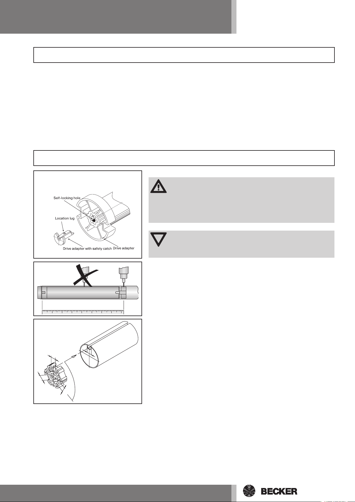
1) Installing a drive adaptor with safety catch:
The insert direction of the drive adaptor safety catch is prescribed by its
shape. When installing the drive adaptor, always ensure that the safety catch
engages. A „clicking“ sound can be heard when the drive adaptor safety
catch engages properly. Pull on the drive adaptor to check that it is located
securely (Fig. 1).
2) Before inserting the drive into the tube, measure the dimensions from the
end of the tube to the centre of the drive adaptor and mark the dimensions on
the tube (Fig. 2).
3) Tubes with shaped sections:
With some drive adaptors, groove widths tolerances in different barrels can
be compensated for by turning the drive adaptor into another groove recess.
These groove recesses have different dimensions and allow you to install the
drive so that it ts exactly (Fig. 3).
5
Page 6

Assembly and Operating Instructions
4
5
4) Round tubes:
Release the tube at the motor end to allow the cam of the limit ring adapter
to be slid into the tube. There must be no clearance between the cam of the
limit ring adapter and the tube (Fig. 4). For limit ring adapters without locating cams the roller tube must be connected to the limit ring adapter using a
4.8 x 10 mm tapping screw.
5) Mount the drive using a suitable limit ring adaptor (A) and drive adaptor
(B). Slide the drive with pre-mounted limit ring adaptor and drive adaptor into
the tube into it connects positively. Ensure that the limit ring adaptor and drive
adaptor are tted into the tube securely (Fig. 5).
The drive adaptor of the tubular drive must be connected to the tube as follows:
Size of drive
[mm]
Ø 35
The drive manufacturer also recommends screwing the opposite end
bracket to the barrel.
Roller shutter tubes–Ø
[mm]
40 mm plastic drive
adapter
Attention!
When drilling the tube ensure that you never drill in the area
around the tubular drive! When inserting the drive into the
tube, do not drive it in or drop it into the tube! (Fig. 2 and 5)
When installing the sun shade system, always ensure that the
motor connection cable and the antenna cannot be damaged
or squashed when the system is in operation.
Torque max.
[Nm]
13
Fastening screws
for drivers (4 x)
at-headed sheet-metal
screw ST 4.8 x 10 DIN 7982
6
Page 7

1) +2a)
Action Response
1) Connecting the tubular drive
Connect the tubular drive to the power supply.
2) Activating programming mode for tubular drive
2a) Activating programming mode for tubular drive by switching on
power supply
Now switch on the power supply. The tubular drive will be in programming mode
for 3 minutes.
Note
If several tubular drives are to be operated in parallel, the pro-
gramming mode for one tubular drive can be deactivated by
sliding the radio switch into the outer position after the power
has been switched on.
If the radio switch is already in this position, slide the switch
back inwards and back to the outer position again.
2b)
3)
4)
Clack-Clack
Rotation switch
Radio switch
2b) Activating programming mode for tubular drive using the radio
switch
Slide the radio switch into the inner
position. If the radio switch is already
in this position, slide the switch outwards and back to the inner position
again.
The tubular drive goes into programming mode for 3 minutes.
3) Programming the master transmitter
Note
Follow the instructions given in the operating manual for the
transmitter. If a transmitter has already been programmed into
the receiver, press and hold the programming button for 10 seconds.
Press the programming button for 3
seconds when the programming mode
is activated.
The tubular drive makes a „clackclack“ sound to conrm.
The programming process is complete.
4) Checking the rotation setting
Press the RETRACT or EXTEND button.
If the curtain moves in the wrong direction, the rotation setting must be changed.
Proceed as follows to do so:
Slide the rotation switch into the opposite position.
The curtain moves in the desired direction.
=> The rotation setting is OK.
Radio switch
Rotation switch
The rotation setting has been changed.
Recheck the rotation setting.
7
Page 8

Assembly and Operating Instructions
Setting the end limits
5) There are two ways to set the end limits:
a) Extend curtain/canopy to desired position and retract to desired position with no end stop
b) Extend curtain/canopy to desired position and retract to end stop
The nal limit position becomes xed, after the tubular drive has turned off automatically, in the desired position, three times.
Note
The end limits can only be set using the master transmitter. The rotation setting must be correct. When
end limits are being set, the tubular drive remains in maintained command mode. The lower end limit must
always be programmed rst.
If, during extension or retraction, the tubular drive stops due to an obstruction, it is possible to extend or
retract the curtain/canopy as necessary in order to move it away from the obstruction. The obstruction
can then be removed and the curtain/canopy adjusted into the desired end limit position.
Action Response
5a)
5a) Lower end limit to upper end limit with no end stop
Note
With this end limit setting there is no automatic curtain/canopy
length adjustment.
Move the curtain/canopy to the desired lower end limit.
5b)
Clack
Clack
Clack
First press the programming button
and, within 3 seconds, also press the
EXTEND button and keep both buttons
pressed.
Then move to the desired upper end
limit.
Now press the programming button
and, within 3 seconds, the RETRACT
button and keep both buttons pressed.
5b) Lower end limit to end stop
Move the curtain/canopy into the desired lower end limit.
First press the programming button
and, within 3 seconds, also press the
EXTEND button and keep both buttons
pressed.
Then move to the xed end stop. The tubular drive switches off auto-
The tubular drive makes a „clack“
sound to conrm.
The tubular drive makes a „clack“
sound to conrm.
The end limits are set.
The tubular drive makes a „clack“
sound to conrm.
matically.
The end limits are set.
8
Page 9

6a)
Action Response
6) Changing the end limit settings
Note
End limit settings can only be changed using the master trans-
mitter.
6a) Reducing the operating range (the desired end limit is within the
possible operating range)
Move to the desired new end limit.
6b)
Clack
Clack-Clack
Clack
First press the programming button
and, within 3 seconds, also press the
EXTEND button for the lower end limit
or the RETRACT button for the upper end limit and keep both buttons
pressed.
6b) Increasing the operating range (the desired end limit is outside the
possible operating range)
Move the curtain/canopy to the end
limit of the direction in which you wish
to increase the operating range.
First press the programming button
and, within 3 seconds, also press the
STOP button and keep both buttons
pressed for 10 seconds.
Move the curtain/canopy to the desired new end limit.
First press the programming button
and, within 3 seconds, also press the
EXTEND button for the lower end limit
or the RETRACT button for the upper end limit and keep both buttons
pressed.
The tubular drive makes a „clack“
sound to conrm.
The new end limit is stored.
The tubular drive makes a „clackclack“ sound to conrm.
The end limit has been deleted.
The tubular drive makes a „clack“
sound to conrm.
The new end limit has been stored.
7a)
Clack-Clack
7) Deleting the end limits
Note
The end limit settings can only be deleted using the master
transmitter.
7a) Deleting the end limits individually
Move the curtain/canopy to the end
limit to be deleted.
First press the programming button
and, within 3 seconds, also press the
STOP button and keep both buttons
pressed for 10 seconds.
The tubular drive makes a „clackclack“ sound to conrm.
The end limit has been deleted.
9
Page 10

Assembly and Operating Instructions
Action Response
7b)
7b) Deleting both end limits
Move the curtain/canopy to any position between the two end limits.
8a)
8b)
Clack-Clack
Clack
First press the programming button
and, within 3 seconds, also press the
STOP button and keep both buttons
pressed for 10 seconds.
The tubular drive makes a „clackclack“ sound to conrm.
The end limits have been deleted.
8) Intermediate position I in extend direction
Note
Intermediate position I is an intermediate position for the cur-
tain/canopy and can be set at any given position between the
upper and lower end limits. Intermediate position I can only be
set if both end limits have already been set.
8a) Setting intermediate position I
Move the curtain/canopy to the desired intermediate position I.
First press the STOP button and, within
3 seconds, also press the EXTEND button and keep both buttons pressed.
8b) Adjustment to intermediate position I
Note
The curtain/canopy moves to the intermediate position I from
the upper end limit.
Press the EXTEND button twice within
one second.
The tubular drive makes a „clack“
sound to conrm.
Intermediate position I has been
stored.
The curtain/canopy moves to intermediate position I.
8c)
10
Clack-Clack
8c) Deleting intermediate position I
Move the curtain/canopy to the desired intermediate position I.
First press the STOP button and, within
3 seconds, also press the EXTEND button and keep both buttons pressed.
The tubular drive makes a „clackclack“ sound to conrm.
Intermediate position I has been deleted.
Page 11

Action Response
9) Intermediate position II in retract direction
Note
This function allows you to move the curtain/canopy from the
lower end limit to intermediate position II. Intermediate position
II can only be set if both end limits have already been set.
9a)
9b)
9c)
Clack
Clack-Clack
9a) Setting intermediate position II
Move the curtain/canopy to the desired intermediate position II.
First press the STOP button and, within
3 seconds, also press the RETRACT
button and keep both buttons pressed.
The tubular drive makes a „clack“
position II
Press the RETRACT button twice within one second.
9c) Deleting intermediate position II
Note
The curtain/canopy moves to intermediate position II from the
lower end limit.
Move the curtain/canopy to the desired intermediate position II.
First press the STOP button and, within
3 seconds, also press the RETRACT
button and keep both buttons pressed.
The tubular drive makes a „clack-
sound to conrm.
Intermediate position II has been
stored.
9b) Adjustment to intermediate
The curtain/canopy moves to intermediate position II.
clack“ sound to conrm.
Intermediate position II has been deleted.
10)
Clack
Clack
Clack-Clack
10) Programming additional transmitters
Note
In addition to the master transmitter, up to 15 additional trans-
mitters can be programmed in the tubular drive.
The end limits must be set prior to programming the radio sun-
and wind sensor.
Press the programming button of the
master transmitter programmed according to point (3) for 3 seconds.
Now press the programming button of
a new transmitter which is not yet programmed in the tubular drive for 3 seconds. In doing so, the programming
mode for the tubular drive is activated
for a new transmitter for 3 minutes.
Now press the programming button of
the new transmitter to be programmed
once again for 3 seconds.
The tubular drive makes a „clack“
sound to conrm.
The tubular drive makes a „clack“
sound to conrm.
The tubular drive makes a „clackclack“ sound to conrm.
The new transmitter has now been
programmed in the drive.
11
Page 12

Assembly and Operating Instructions
Action Response
11a)
11b)
Clack
Clack
Clack-Clack
Clack
Clack
Clack-Clack
11) Deleting transmitters
11a) Deleting transmitters individually
Note
The master transmitter which was programmed in the drive ac-
cording to Point (3) cannot be deleted. It can only be overwritten (see Point 12).
Press the programming button on the
master transmitter for 3 seconds.
Now press the programming button
of the transmitter to be deleted for 3
seconds.
Then press the programming button
of the transmitter to be deleted once
again for 10 seconds.
11b) Deleting all transmitters (except master transmitter)
Press the programming button on the
master transmitter for 3 seconds.
Now press the programming button on
the master transmitter once again for
3 seconds.
Now press the programming button on
the master transmitter once again for
10 seconds.
The tubular drive makes a „clack“
sound to conrm.
The tubular drive makes a „clack“
sound to conrm.
The tubular drive makes a „clackclack“ sound to conrm.
The transmitter has been deleted from
the tubular drive.
The tubular drive makes a „clack“
sound to conrm.
The tubular drive makes a „clack“
sound to conrm.
The tubular drive makes a „clackclack“ sound to conrm.
All transmitters (except master transmitter) have been deleted from the
receiver.
12a)
Clack-Clack
12) Overwriting master transmitter
There are two ways of overwriting the master transmitter:
a) Put tubular drive into programming mode by switching on power supply
b) Put tubular drive into programming mode using radio switch
12a) Putting tubular drive into programming mode by switching on
power supply
Switch off the power supply to the tubular drive and reconnect after 5 seconds.
Note
To ensure that the new master transmitter is programmed in the
desired tubular drive only, the programming mode for all other
tubular drives which are connected to the same power supply
must be deactivated. To do so, after the power supply has been
switched back on, execute a command control (adjust or stop)
with the transmitter of these tubular drives or move the radio
switch from the inner to the outer position. If the radio switch is
already in this position, slide the switch to the inner position and
back to the outer position again.
Now press the programming button of
the new master transmitter for 10 seconds.
The tubular drive goes into programming mode for 3 minutes.
The tubular drive makes a „clackclack“ sound to conrm.
The new master transmitter has been
programmed in and the old deleted.
12
Page 13

12b)
Action Response
12b) Putting the tubular drive into programming mode using the radio
switch
Slide the radio switch into the inner
position. If the radio switch is already
in this position, slide it outwards and
back to the inner position again.
The tubular drive goes into programming mode for 3 minutes.
Now press the programming button of
the new master transmitter for 10 seconds.
Clack-Clack
The tubular drive makes a „clackclack“ sound to conrm.
The new master transmitter has been
programmed in and the old deleted.
Technical Data
Type P3/30PSF P5/20PSF P5/30PSF P9/16PSF
Nominal torque (Nm) 3 5 5 9
Output speed (min
Limit switch range 64 revolutions
Mains voltage 230V/50Hz
Power consumption (W) 85 115 11 5 110
Nominal current consumption (A) 0,36 0,47 0,47 0,47
Operating mode S2 4 Min.
Protection class IP 44
Min. tube diameter (mm) 37
Frequency 868,3 MHz
-1
) 30 20 30 16
What should you do, if...?
Malfunction Cause Solution
Tubular drive is not running. 1. No transmitter has been programmed.
2. Transmitter is outwith the range of the
tubular drive.
3. Transmitter has been operated outwith the
range several times.
4. Batteries in the transmitter have been
incorrectly inserted, not inserted at all or
are empty.
5. Faulty electrical connection.
6. Thermal cut-out function in the tubular
drive has been activated.
You are unable to change the
axle direction.
The axle direction is incorrect
after deleting the end limits.
Tubular drive has stopped at
random and won’t run in the
given direction.
End limits are stored in the tubular drive. Start up the tubular drive via a start com-
The axle direction switch is in the wrong position.
1. Tubular drive has detected an assumed
load.
2. Tubular drive is overloaded.
1. Programme new transmitter.
2. Move transmitter into the range of the
tubular drive.
3. Activate the control or stop button on the
transmitter at least 5 times.
4. Insert batteries properly or replace batteries.
5. Check electrical connection.
6. Wait 5-10 minutes.
mand and deactivate with a stop command.
Then delete the end limit settings using the
programming and stop buttons.
Slide the axle direction switch to the opposite
position.
1. Run the drive briey in the opposite direction, then activate the desired direction
again.
2. Use a tubular drive with a greater torque.
13
Page 14

Assembly and Operating Instructions
14
Page 15

15
Page 16

2010 300 258 0d 06/11
 Loading...