

Becker NR 3320, NR 3320-01, NR 3330, NR 3330-01, NR 3320-02 Operating Instructions Manual
...Page 1
BECKER FLUGFUNKWERK GMBH
Baden Airpark B 108
OPERATING INSTRUCTIONS
Navigation-Receiver
NR 3320 - (01) / - (02)
NR 3330 - ( 01) / - (02)
D-77836 Rheinmünster (Germany)
Tel. +49 (0) 7229 / 305-0
Telex 781 271 beflu
Fax +49 (0) 7229 / 305217
Subject to technical changes
Page 2

Becker Flugfunkwerk GmbH
Baden Airpark, Gebäude B 108
77836 Rheinmünster (Germany)
Tel. +49 (0) 7229 / 305-0
Failure description
Fax +49 (0) 7229 / 305-217
Unit type : Serial number :
Aircraft type :
Brief description of the failure :
.................................................................................................................
.................................................................................................................
.................................................................................................................
.................................................................................................................
Should the fault only occur sporadically, please answer the following
questions :
The fault occurs after . . . . . minutes of operation.
The fault occurs under the following environmental conditions :
p low temperature
p high temperature
p high humidity
p vibration
The fault is engine speed-dependent and occurs above/below . . . . . rpm.
Should any problems arise, I may be contacted under the following adress :
...................................................................................
..................................................................
..................................................................
I am available between 8 a.m.
and 4 p.m. under the following
telephone number :
© Copyright by Becker Flugfunkwerk
Article-No.: 0516.718-071 Issue 12/97
.............................................................. office: ...................................
.............................................................. private : ...................................
Page 3

REPAIR INSTRUCTIONS
If an equipment fault the unit may be sent to a Becker Dealer or the Be-
cker Product Support together with a description of the fault. The com-
pleted fault description shortens the repair times and hence lowers the
resultant costs.
These operating instructions do not replace the equipment manuals lis-
ted below.
q
Equipment manuals
To be purchased from the manufacturer or Becker Dealer:
Installation and Operation
DV 38001.03 Article-No.: 0504.971-071
Maintenance and Repair
DV 38001.04 Article-No.: 0504.981-071
Operating Instructions Article-No.: 0516.718-071
BECKER NR 3320 - ( ) / NR 3330 - ( )
Page 32 Issue 12/97
TABLE OF CONTENTS
Page
IMPORTANT 1
INTRODUCTION 1
SAFETY PRECAUTIONS 3
GENERAL INFORMATION 5
p
Short description of NAV receiver 5
CONTROL AND INDICATORS 9
p
NAV receiver 9
OPERATING INSTRUCTIONS 13
p Operating instructions NAV receiver 13
p Switching on the navigation receiver 13
p
TEST mode (by pressing the TEST button) 14
p VOR mode 14
p
Monitoring flight and weather information 15
p
LOC mode 15
p
GS mode with the NR 3320 - ( ) 16
p
Operation of the various modes 16
p
Frequency setting mode 17
p
Frequency preselection mode 18
p
Channel setting mode 19
p
Storage procedure 19
p
Service mode (equipment configurations) 20
p
Deletion of all stored frequencies in the storage channels 24
Operating Instructions
Issue 12/97 Page 1
Page 4

Page
TECHNICAL DATA 25
p
General data 25
p
VOR/LOC receiver 26
p
VOR/LOC system functions 27
p
GS receiver and functions in the NR 3320 - ( ) 28
p
Indicators 29
REPAIR INSTRUCTIONS 30
p
Equipment manuals 30
BECKER NR 3320 - ( ) / NR 3330 - ( )
Page 2 Issue 12/97
Centering error under all £ 13% of standard deflection
conditions, listed in RTCA DO-192
with 95% probability
GS needle output max. of 3 needles and/or flags
with 1 kW each
GS warning flag output max. of 3 needles and/or flags
with 1 kW each
q
Indicators
VOR/LOC indicator (singlepointer) IN 3300 - (4) / - (9) or
for NR 3330 - (01) equivalent indicator
VOR/LOC indicator (crosspointer) IN 3300 - (3) / - (5) - (8) or
for NR 3320 - (01) equivalent indicator
Compatible indicators may also be used if they meet relevant require-
ments. They must have equivalent or better environmental performan-
ce characteristics as the indicators listed above with respect to tempe-
rature, altitude, humidity and vibration.
Operating Instructions
Issue 12/97 Page 31
Page 5

Resolver output standard as per ARINC 407
VOR/LOC needle output max. of 3 pointers and/or flags
with 1 kW each
VOR/LOC warning flag output max. of 3 pointers and/or flags
with 1 kW each
TO/FROM output max. of 3 pointers and/or flags
with 1 kW each
Autopilot output for VOR course tracking and
ILS mode
q GS receiver and functions in the NR 3320 - (01) / - ( 02)
Receiver type single-conversion super-
heterodyne receiver
Frequency range 329.15 MHz . . . 335.00 MHz
No. of channels 40
Channel spacing 150 kHz
Sensitivity £ -80dBm for complete
disappearance of warning flag
Bandwidth ³ ± 20 kHz at 6 dB
Selectivity ³ 42 dB at DF ³ 150 kHz
BECKER NR 3320 - ( ) / NR 3330 - ( )
Page 30 Issue 12/97
IMPORTANT
Carefully read these operating instructions right through before attemp-
ting to operate the NAV receiver.
Keep these operating instructions carefully. They contain important sa-
fety and operating instructions for the NAV receiver.
INTRODUCTION
Thank you for purchasing the BECKER NAV receiver. The NAV recei-
ver can be installed in the instrument panel or centre console or opera-
ting console and is easy to operate. The technology used is to the state
of the art.
To fully utilise the capabilities of your NAV receiver, please carefully
read these operating instructions right through before you start opera-
ting the set.
If you have any questions regarding the operation of the NAV recei-
ver, please get in touch with your nearest Becker Dealer or with the Be-
cker Product Support.
Operating Instructions
Issue 12/97 Page 3
Page 6

The WARNING, CAUTION and NOTE highlights have the following
meanings:
Failure to comply, or incorrect compliance,
with these instructions or procedures can lead
to injuries or fatal accidents.
Failure to comply, or incorrect compliance,
with these instructions or procedures can lead
to damage to equipment.
NOTE
Feature to which attention should be drawn.
l
Never connect the NAV receiver to alternating current voltage or
to voltage sources exceeding 32 V DC.
l
Never connect the NAV receiver with reversed polarity to a volta-
ge source.
l
The installation of the NAV receiver in ambient temperatures be-
low - 55°C or above + 85°C is to be avoided.
l
Switch off the unit when starting or shutting down engines.
BECKER NR 3320 - ( ) / NR 3330 - ( )
Page 4 Issue 12/97
WARNING
CAUTION
CAUTION
AGC £ 3 dB from -87 dBm . . . -10
dBm
Distortion £ 10%
Audio output 150 mW into 300W symm.
NAV signal (composite) 500 mV at 30 Hz, mod = 30%
VOICE filter ³ 20 dB reduction
DME remote control parallel, with 2-out-of-5 code
in accordance with ARINC 410
q VOR/LOC system functions
Sensitivity £ -93 dBm for full direction
sensitivity
Bearing error under normal £ ± 2°
condition
Bearing error under all £ ± 2.7°
conditions listed in
RTCA DO-196, with 95%
probability
Course deviation for full ± 10°
scale deflection
LOC centering error under all £ 11% of standard dflection
conditions, listed in RTCA DO-195
with 95% probability
Operating Instructions
Issue 12/97 Page 29
Page 7

Max. operating altitude 50 000 ft.
Dimensions
Front panel 47.5 x 146 mm
Casing depth 183 mm with antenna jack
Weight of
NR 3320 - (01) approx. 0,885 kg
NR 3320 - (02) approx. 0,835 kg
NR 3330 - (01) approx. 0,745 kg
NR 3330 - (02) approx. 0,695 kg
q VOR/LOC receiver
Receiver type triple-conversion
superheterodyne receiver
Frequency range 108.00 MHz - 117.95 MHz
No. of channels 200
Channel spacing 50 kHz
IF-Frequencies 1,2,3 71.05 MHz, 21.4 Mhz,
455 kHz
Sensitivity (audio) £ -93 dBm for ³ 6 dB SINAD
Bandwidth ³ 12 kHz at 6 dB
Selectivity ³ 65 dB at DF ³ ± 50 kHz
BECKER NR 3320 - ( ) / NR 3330 - ( )
Page 28 Issue 12/97
SAFETY PRECAUTIONS
l
Switch off the navigation receiver before starting or shutting
down engines !
l
The NAV system should be connected to the aircraft power supp-
ly by its own 1 A circuit breaker.
l
Warning! Reception is only possible when there is a quasi-optical
sight to the VOR station.
l
When the warning flag in the display unit appears, the course de-
viation needle must then not be used in the continuing flight !
l
Warning! When flying with the autopilot locked on to VOR, the
OBS must not be rotated because any change in the off-course
needle is followed by the autopilot !
l If the off-course needle instrument fails, no warning flag appears.
Check the off-course needle by activating the TEST function. The
course deviation needle must deflect halfway. Important to check
before approach to landing !
l
During approaches on the back beam, a needle deflection no
longer corresponds to a command indication. In this special
case, course corrections must be made opposite to the needle
deflection !
l
When overflying VOR stations a cone of silence of ± 45°occurs
in which the warning flag appears and the course deviation need-
le stays in the mid position.
l
When flying over mountains the course deviation needle may
deviate about the mid position (reflections) when approaching or
leaving VOR stations. Doppler VOR stations produce substantial-
ly more stable indications under these conditions.
Operating Instructions
Issue 12/97 Page 5
Page 8

l
EMC note: If the antennas of transmitting equipment and of the
navigation receiver are not sufficiently decoupled, it is possible
that the warning flag may appear during transmission or the cour-
se deviation needle may deflect. Inadequate decoupling is possi-
ble with airframes made of wood or synthetic materials or where
the antennas are mounted close together.
BECKER NR 3320 - ( ) / NR 3330 - ( )
Page 6 Issue 12/97
TECHNICAL DATA
q
General data
Supply voltage + 13.75 V or + 27.5 V DC
Current consumption of typ. 340 mA
NR 3320 - (01) (without panel illumination)
Current consumption of typ. 300 mA
NR 3320 - (02) (without panel illumination)
Current consumption of typ. 280 mA
NR 3330 - (01) (without panel illumination)
Current consumption of typ. 240 mA
NR 3330 - (02) (without panel illumination)
Current consumption of typ. 230 mA at 27.5 V
panel illumination typ. 460 mA at 13.75 V
typ. 1.4 A at 5 V
Overcurrent capacity of
internal fusing 1,5 A
Recommended external
overcurrent protection 1 A without panel illumination
Operating temperature range - 20° C ... + 55° C
(short-time to + 70°C)
Storage temperature range - 55°C ... + 85°C
Interface RS 422
Operating Instructions
Issue 12/97 Page 27
Page 9

Release the volume control
Call up function “Poti” using the MDE key. The following display appe-
ars:
left LC-Display Poti
right LC-Display ON or OFF
Select the required setting using the kHz frequency selector switch and
store the selection by pressing the STO key.
OFF = The audio output signal is off and can not be
adjusted with the volume control.
ON = The audio output signal can be adjusted with the
volume control (standard setting).
Ending of the service mode
The navigation receiver must be switched off to finish end the service
mode.
q
Deletion of all stored frequencies in the storage channels
Press and hold the STO and MDE keys whilst switching on the navigati-
on receiver. All the stored frequencies in the storage channels are dele-
ted, with the exception of channel 01.
BECKER NR 3320 - ( ) / NR 3330 - ( )
Page 26 Issue 12/97
GENERAL INFORMATIONS
The NAV receiver NR 3320 - (01) is designed to receive and convert
VOR and LOC signals on 200 channels in the frequency range between
108.00 MHz and 117.95 MHz.
The NAV receiver NR 3320 - (02) is designed to receive VOR and LOC
signals on 200 channels in the frequency range between 108.00 MHz
and 117.95 MHz. It supplies the NAV composite signal to an external
VOR/LOC converter. Both NAV receiver include a glideslope receiver.
The glideslope receiver is designed to receive and convert GS signals
on 40 channels in the frequency range between 329.15 MHz and
335.00 MHz.
The NAV receiver NR 3330 - (01) is designed to receive and convert
VOR and LOC signals on 200 channels in the frequency range between
108.00 MHz and 117.95 MHz.
The NAV receiver NR 3330 - (02) is designed to receive VOR and LOC
signals on 200 channels in the frequency range between 108.00 MHz
and 117.95 MHz. It supplies the NAV-composite signal to an external
VOR/LOC converter.
q
Short description of NAV receiver
The NAV receiver is designed as a single unit for installation in the in-
strument panel or operating console of aircraft. Its dimensions corre-
spond to the ARINC standard dimensions for control equipment. It is
held in place by four DZUS fasteners. All controls and indicators are lo-
cated on the front panel.
Operating Instructions
Issue 12/97 Page 7
Page 10

The back side of the unit contains:
· the BNC-antenna jacks for the VOR/LOC-receiver
· the TNC-antenna jacks for the GS-receiver
· the 15-pole D-sub connector plug (female) for the outputs of the
VOR/LOC converter board (NR 3320 - ( 01) and NR 3330 -(01)
only)
· the 9-pole D-sub connector plug (female) for the I/O Outputs of
the RS 422 interface.
· the 25-pole D-sub connector plug (male) unit connector plug
The electronic elements of the unit are distributed among the following
boards, which are linked with one another by means of p.c. connectors:
1. Chassis board
2. VOR/LOC receiver board
3. VOR/LOC converter board
4. GS receiver board
5. Processor board
6. Display board
7. Interface board
The interface board and the processorboard are mounted and fastened
by means of four screws on the frame of the control head. The display
board with the two liquid crystal displays is located between the front
plate and the panel.
BECKER NR 3320 - ( ) / NR 3330 - ( )
Page 8 Issue 12/97
Entry of password to interlock the equipment configuration
Call up the “COdE” function using the MDE key. The following display
appears:
left LC-Display COdE
right LC-Display 0000
Set any 4-digit numerical code. Using the MHz frequency selector
switch, select the character (two digit left) and kHz frequency selector
switch, select the character (two digit right) . Store the numerical code
by pressing the STO key.
NOTE
As soon as a password is given a “0000" appears in the right
LC-Display when the service mode is called up. The numeri-
cal code must then be input using the MHz and kHz frequen-
cy selector switch and press the STO key. If the navigation
receiver detects a false numerical code, it automatically swit-
ches to the last mode. If the password is to be erased or chan-
ged, this is done by calling up the service mode using the old
password. The COdE function is then chosen and either a
”0000" is entered everywhere or the changed numerical code
is entered.
Operating Instructions
Issue 12/97 Page 25
Page 11

Release the frequency storage
Call up function “CS” using the MDE key. The following display appe-
ars:
left LC-Display CS
right LC-Display ON or OFF
Select the required setting using the kHz frequency selector switch and
store the selection by pressing the STO key.
OFF = The storage of frequencies in the individual chan-
nels is not possible.
ON = Storage of frequencies in the individual channels
is
possible (standard setting).
Erase stored frequencies
Call up function “dEL” using the MDE key. The following display appe-
ars:
left LC-Display dEL
right LC-Display CH channel number
Select the channel to be erased using the kHz frequency selector switch
(steps of 1) or MHz frequency selector switch (steps of 10) switch. The
stored frequency is erased by pressing the STO key. The channel
No. 1 cannot be erased.
“ch” = free channel
“CH” = occupied channel (can be overwritten).
BECKER NR 3320 - ( ) / NR 3330 - ( )
Page 24 Issue 12/97
The microcontroller as well as its storage and peripheral components
are located on the processor board.
The GS receiver board is above the chassis board; and the VOR/LOC
receiver board and the VOR/LOC converter board are mounted below
the chassis board. Each of these three circuit boards is attached to the
chassis with four screws.
The VOR/LOC receiver isa triple-conversion superheterodyne receiver
and operates in the frequency range from 108.00 MHz to 117.95 MHz
with a channel separation of 50 kHz. The injection signal for the mixer is
generated by a voltage-controlled oscillator (VCO). The VCO is control-
led by digital frequency synthesizer which is mounted on the chassis
board. Digital frequency synthesis and storage are microproces-
sor-controlled.
The VOR/LOC conversion takes place on the VOR/LOC converter
board. The converted signals can thenbe readoff the VOR/LOC pointer
of the connected VOR/ILS indicator.
The VOR/LOC converter board is omitted in the NR 3320 - (02) and
NR 3330 - (02) type. This type supplies only the NAV composite signal
to the VOR/LOC evaluation (for indicators with integrated VOR/LOC
evaluation).
The GS receiver is designed as a single-conversion superheterodyne
receiver and operates in the frequency range between 329.15 MHz and
335.00 MHz with a channel separation of 150 kHz. The injection fre-
quency for the receiver is generated by a voltage-controlled oscillator
(VCO). The VCO is controlled by a digital frequency synthesizer which
is mounted on the chassis board. The digital frequency synthesizer ope-
rates in conjunction with the microcontroller of the NAV receiver. The
converted GS signals can be read off the GS pointer of the connected
indicator.
Operating Instructions
Issue 12/97 Page 9
Page 12

The NAV receiver contains two liquid crystal frequency displays, on
which two different frequencies can be set using the tuning dials. The
microcontroller allows programming of an “active” and a “preset” fre-
quency which can be quickly swapped during VOR/LOC operation by
pressing the transfer button.
The NAV receiver possesses a built-in testing function. By pressing the
TEST button it is possible to check the proper functioning of both liquid
crystal displays, the VOR/LOC converter and the GS converter.
The tuning dials of the NAV receiver can also be used to remotely con-
trol a DME unit (parallel with 2-out-of-5 code).
BECKER NR 3320 - ( ) / NR 3330 - ( )
Page 10 Issue 12/97
On the right two digits display the version number and on the left
two digits display the software Spec..
“Fr” appears in the left indication and OFF or ON in the right indication
after display the version number and software Spec..
NOTE
In the service mode, the navigation receiver is not ready
for operation
The parameters are selected in stages in the service mode by pressing
the MDE key.
Release the frequency setting (channel selection only)
Call up function “Fr” using the MDE key. The following display appears:
left LC-Display Fr
right LC-Display ON or OFF
Select the required setting, using thekHz frequency selector switch and
store the setting by pressing the STO key.
OFF = Frequency setting not possible. The navigation
receiver can only work on the frequencies stored
in the individual channels.
ON = Frequency setting possible (standard setting).
Operating Instructions
Issue 12/97 Page 23
Page 13

2.
Press the STO key. The next free channel is shown flashing “ch”.
The channel in which the frequency is to be entered is selected
using the MHz and kHz frequency switches. Channels which are
already occupied are indicated by “CH” and can be overwritten.
3.
Press the STO key. The frequency is stored in the selected chan-
nel and the storage procedure ended.
NOTE
If no input (action) takes place for more than 7 seconds du-
ring the storage procedure, the operation is automatically ab-
orted off. A storage operation can be aborted off at any time
by pressing the MDE key.
q Service mode (equipment configurations)
The service mode is meant to enable the ground technicians to set
the equipment configuration and must not be used in flight.
The following settings can be changed or set:
Fr Inhibiting the frequency setting
(channel selection only (ON/OFF)
CS Inhibiting the frequency storage (ON/OFF)
dEL Erasure of stored frequencies
COdE Entering a password to interlock the
equipment configuration
Poti ReIease the volume control (ON/OFF)
Switch off the navigation receiver. Press and hold the MDE key whilst
the navigation receiver is being switched on. The right display must
show the version number and software Spec. approximately 2 seconds.
BECKER NR 3320 - ( ) / NR 3330 - ( )
Page 22 Issue 12/97
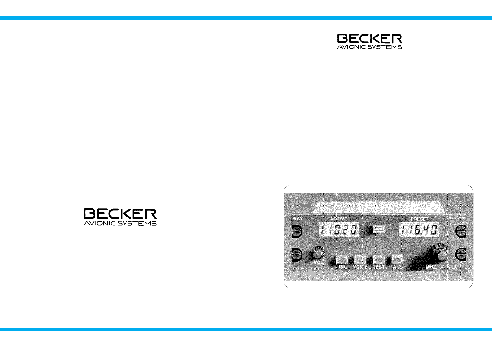
CONTROLS AND INDICATORS
q
NAV receiver
Meaning of symbols on controls and indicators
Symbol Description Function
1
ON/OFF switch
combined with
volume control
ON/OFF switch and volume
control.
2
TEST key
Tests functional status of
both LCDs, the VOR/LOC- /
GS-converter and the indi-
cator.
3
IDT key
Switching the suppression
of the VOR identification on
or off when monitoring flight
and weather information.
4
STO key
Storage of set frequency or
other settings.
Operating Instructions
Issue 12/97 Page 11
IDT
TEST
STO
Page 14

Symbol Description Function
5
Function key
Selection of mode and se-
lecting the parameter in the
service mode.
6
Exchange key
Frequency preselection:
Exchange of preset
fre-quency and active fre-
quency.
7
Frequency selector
Switching the indicated
switch frequency in 1 MHz
(outer rotary switch) steps or
the storage channel up-
wards or downwards in
steps of 10.
8
Frequency selector
Switches the indicated (in-
ner rotary switch) frequency
in 50 kHz steps or the stora-
ge channel by 1 step in each
case upwards or
downwards, without carry
over.
BECKER NR 3320 - ( ) / NR 3330 - ( )
Page 12 Issue 12/97
MDE
< - >
q
Channel setting mode
Select the channel setting mode using the MDE key. The last indicated
storage channel appears in the right display and the stored frequency is
shown in the left display. The navigation receiver is ready to receive on
this frequency.
Select the require channel using the kHz frequency selector switch
(single steps) or MHz frequency selector switch (steps of ten).
NOTE
Only occupied storage channels can be selected.
Change of mode
To change the mode, press the MDE key.
q
Storage procedure
A storage procedure can be performed at any time and is activated by
pressing the STO key.
1.
Press the STO key. The active frequency remains indicated in the
left display. The navigation system is ready to receive on this fre-
quency. The active frequency is shown flashing in the right display
and in the frequency preselection mode, the preset frequency. Set
the required frequency using the kHz frequency selector switch
and the MHz frequency selector switch.
Operating Instructions
Issue 12/97 Page 21
Page 15

Change of mode
To change the mode, press the MDE key.
q
Frequency preselection mode
Select the mode using the MDE key. The last indicated active and pre-
set frequency are shown in the left and right indication respectively.
The preset frequency (right indication) is set using the MHz and kHz fre-
quency selector switches. Pressing the <-> exchange key changes over
between the active and preset frequency.
NOTE
The navigation receiver is always ready to receive on the fre-
quency shown in the left indication.
Change of mode
To change the mode, press the MDE key.
BECKER NR 3320 - ( ) / NR 3330 - ( )
Page 20 Issue 12/97
LCD (liquid crystal display) elements
Symbol Description Function
9
(left indication)
(active frequency)
Indication of active
reception frequency.
1
0
(right indication)
Indication of preset
reception frequency in the
frequency preselection
mode.
1
0
(right indication)
CH indication steady:
Indicates the storage
channel.
1
0
(right indication)
CH indication flashes:
If the initiated storage
operation is not completed
by pressing the store key.
1
0
(right indication) ON indication.
1
0
(right indication) OFF indication.
Rear of unit
BNC 50 Ohm antenna connecting sockets
VOR/LOC-Receiver
TNC 50 Ohm antenna connecting sockets GS-Receiver
Operating Instructions
Issue 12/97 Page 13
Page 16

25-pin Equipment connector for connecting
D sub-male the installation wiring
15-pin Equipment connector for connecting
D sub-male the installation wiring Indicator IN 3300 - ( )
9-pin Equipment connector for connecting interface
D sub-male RS 422
BECKER NR 3320 - ( ) / NR 3330 - ( )
Page 14 Issue 12/97
Channel setting mode
Display of the stored frequencies in the storage channels. The
channels can be selected using the frequency selector switches.
NOTE
All setting or frequency changes are automatically stored af-
ter two seconds. This means that changes which are made
immediately before switching off are not stored. This does
not include deliberate storage operations performed using
the STO key.
q
Frequency setting mode
The left display indicateds the active frequency. The right display is swit-
ched off.
The active frequency can be changed with the MHz and kHz frequency
selector switches.
The set frequency is held even when the unit is switched off.
Operating Instructions
Issue 12/97 Page 19
Page 17

q
GS mode with the NR 3320 - ( )
1. Set the frequency of the localizer.
2.
Switch on the VOR/LOC identification (press the IDT key, ON ap-
pears briefly in the display). Monitor the Morse identification signal
and compare it with the identification signal of the wanted locali-
zer.
3. If a glidepath signal of sufficient strength is present, the GS war-
ning flag disappears from the field of view.
4. The GS needle (horizontal command needle) deflects during the
approach in the direction in which the flight level has to be correc-
ted in order to obtain the specified glidepath. A mid position of the
needle means that the aircraft is on the glidepath.
q
Operation of the various modes
The navigation receiver contains various functions which areperformed
under three modes. The individual modes are selected by pressing the
MDE key.
Frequency setting mode
Display of the active frequency in the left indication. The right
indication is switched off. The active frequency can be directly
changed using the frequency selector switches. Frequencies
can also be stored in the individual storage channels.
Frequency preselection mode
Display of the active and preset frequency. The preset frequency
can be set using the frequency change switches. Pressing the
exchange key changes over from the active to the preset fre-
quency. Frequencies can also be stored in the individual storage
channels.
BECKER NR 3320 - ( ) / NR 3330 - ( )
Page 18 Issue 12/97
OPERATING INSTRUCTIONS
q
Operating instructions NAV receiver
Preparation
Switch on the aircraft power supply (check that the circuit breaker for the
navigation receiver is set).
Do not switch on the navigation receiver if engines or motors
are being started up or shut down.
q
Switching on the navigation receiver
1. Rotate the volume control clockwise and switch on the navigation
receiver.
2. Both LCDs must show the numbers 188.88 flashing approximately
2 seconds. If the test is positive, the navigation receiver automati-
cally switches to the mode which was selected before switch-off. If
the test is negative, the LCD flashes for approximately 5 seconds.
In all modes, disturbances of the navigation system are displayed
in the form of fault messages.
l
E2 synthesizer failed,
l
E3 EEPROM fault
4. A comprehensive description of the various modes follows the ge-
neral operating instructions.
Operating Instructions
Issue 12/97 Page 15
WARNING
Page 18

q
TEST mode (by pressing the TEST button)
Press the TEST key. All digits should flash on and off in both liquid crys-
tal displays (display test). At thesame time, the VOR/LOC pointer (verti-
cal needle) of the connected indicator should deflect fully and the
VOR/LOC warning flag should disappear from view. In the NAV re-
ceiver NR 3320 - (1) the GSpointer (horizontalneedle) of the connected
indicator should deflect fully and the GS flag should disappear from
view.
q
VOR mode
1. Set the frequency of the wanted VOR station.
2.
To monitor the identification signal, press the IDT key (ON appe-
ars briefly in the (right indication) of the LC display). Monitor the
identification signal and compare it with the identification signal of
the wanted VOR station. Adjust the volume using the VOL control.
3. If an evaluable VOR signal enables a safe bearing to be establis-
hed, the vertical needle deflects and the VOR/LOC flag disappe-
ars from the field of view.
4.
Rotate the omnibearing selector (OBS) on the display unit until
the TO/FROM display indicates TO and the vertical needle has
settled in the mid position. The heading indication then indicates
the magnetic course to the VOR station.
5. Course deviations during the approach are indicated in the directi-
on of correction by the vertical needle (course correction in the di-
rection of the needle deflection).
BECKER NR 3320 - ( ) / NR 3330 - ( )
Page 16 Issue 12/97
6. When overflying the VOR station, the TO/FROM display moves
from TO to FROM. If the flight is continued on the same heading,
the course indication shows the magnetic position line of the VOR
station which the aircraft is approaching, with the vertical needle
in the mid position.
q
Monitoring flight and weather information
1.
Press the IDT key. The word OFF appears briefly in the (right indi-
cation) of the LC display. Identification transmissions are faded
out.
2. The fading out of the VOR/LOC indentification signal means that
flight and weather information can now be monitored.
3.
Press the IDT key again. The word ON appears briefly in the dis-
play. The identification signal can now be monitored.
q LOC mode
1. Set the frequency of the required localizer.
2.
Switch on the VOR/LOC identification (press the IDT key, ON ap-
pears briefly in the display). Monitor the Morse identification signal
and compare it with the identification signal of the wanted locali-
zer.
3. The vertical needle (command needle) deflects during the appro-
ach to the localizer in the direction in which the course is to be
corrected in order to obtain the correct landing course. A mid posi-
tion of the needle means that the aircraft is on the correct line for
landing.
Operating Instructions
Issue 12/97 Page 17
 Loading...