

Page 1

IC Amplifier
Unit
IC 6100-2-(01)
IC 6100-3-(01)
Installation and Operation
Manual
Issue 1
DV 64480.DIC.01
September 2013
Becker Avionics, Inc. 10376 USA Today Way • Miramar, Florida 33025 • USA
Telephone +1 (954) 450 3137 • Fax ++1 (954) 450 3206
http://www.beckerusa.com • e-mail: info@beckerusa.com
Page 2

FIRST ISSUE AND CHANGES
Issue 1 September 2013
List of effective pages
Page No.: Date : Page No.: Date :
Title
1 -I - 1-II
1-1 - 1-14
2-I - 2-II
2-1 - 2-12
3-I - 3-II
3-1 - 3-11
09/2013
09/2013
09/2013
09/2013
09/2013
DV 64480.DIC.01 / Article Number 0900.149.071
© 2013 by Be cker Avionics, Inc. / All rights reserved
09/2013
09/2013
Page 3

Page 1-I
IC6100
Table of Contents
Section 1 GENERAL INFORMATION Page
1.1 1-1
1.2 1-1
1.3 1-2
1.3.1 1-2
1.3.2 1-2
1.3.3 1-4
1.4 1-5
1.4.1 1-5
1.5 1-6
1.5.1 1-6
1.5.2 1-6
1.5.2.1 1-6
1.5.2.2 1-6
1.5.3 1-7
1.5.4 1-7
1.5.5.1 1-8
1.5.5.2 1-8
1.5.5.3
1.5.5.4
1-8
1.5.5.5
1-8
1.5.5.6
1-9
1.5.5.7
1-9
1.5.5.8
1-9
1.5.5.9
1-9
1.5.6
1-9
1.5.7
1-10
1.5.7.1
1.5.7.2
1-10
1.5.7.3
1-10
1.5.7.4
1-11
1.5.8
1-11
1.5.9
1-11
1.5.10
1-12
1.5.11
1-12
1.6
1-12
1.7
1-13
1.8
1-13
1.9
1-13
1-13
Introduction
Application
General description
Mechanical description Electrical
description
Memory device EM6100-(XXX)
Identification of article
Types of Intercom Amplifier Unit
Technical data
Power supply
Monitoring
Fixed inputs
Warning inputs
Headphone amplifier
Aural tone generator
Mike input (standard carbon mike)
Mike input (dynamic mike)
Automatic gain control (AGC)
Sidetone
CVR connection
Control inputs (discretes)
Control outputs (discretes)
Back-up monitor
DC OUT 28 V
Intercom operation
Build In Test Equipment (BITE)
Power On BuiId In Test (PBIT)
Continuous Build In Test (CBIT)
Build In Test Representation
Back-up operation
Programming mode
Mechanical data
Unit connectors
DV 64480.DIC.01 Issue 1 Sep./2013
Environmental conditions
Software
Approvals
Scope of delivery
Accessories (not contained in the scope of delivery)
1-10
Page 4

Page
1-II
DV 644 80.DI C.0 1 Issue 1 Sep./2013
IC6100
BLANK
Page 5

DV 64480.DIC.01 Issue 1 Sep./2013 Page
1-1
IC6100
Section 1 GENERAL INFORMATION
1.1 Introduction
The Becker IC 6100 IC Amplifier Unit is described in the "Installation and
Operation" DV 64480.DIC.01 and "Maintenance and Repair" DV 64480.DIC.02
The manuals contain the following sections:
Section DV 64480.DIC.01 DV 64480.DIC.02
1 General Information X X
2 Installation X X
3 Operation
X
X
4 Theory of Operation X
5 Maintenance and Repair X
6
Illustrated Parts
List
X
7 Modification and Changes X
8 Circuit Diagrams X
9 List of the used Abbreviations X
1.2 Application
The IC6100, IC Amplifier Unit, is part of the Digital Voice Communication System DVCS6100 and is
provided for installation in aircrafts and helicopters. Together with the ACU610X Audio Control Units
and the REU6100 Remote Electronic Unit, the IC6100 complement the intercom system of the
aircrafts and/or helicopters, in cases when it is needed more operators positions.
Page 6

Page
1-2
DV 6 4480.DIC .01 Issu e 1 Sep./2013
IC6100
1.3 General Description
1.3.1 Mechanical Description
The IC6100 IC Amplifier Unit is designed for installation in the avionics compartment of an aircraft.
The IC6100 IC Amplifier Unit is a device in standard ¼ ATR short case.
Two unit connectors are fitted on the front and two unit connectors on the back side. The IC Amplifier Unit consists
of the following circuit boards:
• Dual-Headset Amplifier Board (max. 3 ea.),
• Analog Board,
• DSP Board,
• CPU Board,
• Bus Board,
• Connector Board.
1.3.2 Electrical Description
The IC6100 IC Amplifier Unit is an Intercom System, software configurable and accordingly influences and
processes all incoming and outgoing audio signals from the headsets and from IC Ring, performs the logical
functions necessary for aircraft intercommunication and provides the creation of up to 2 IC Ring groups which
can communicate together or isolated at will, by using the Alert Tone activation Line #2. Also allows the
generation of up to 8 different aural tone signals which may be activated through discrete control lines, which can
be used as HOT MIKE lines (up to 6 as Hot mike) or Alert Tone activation lines (alert tones from 3 to 8) and 2 as
Alert Tone activation lines or one as alert tone (#1) and the other as ISOLATION line (#2).
The IC Amplifier Unit provides the following features:
6 balanced SW configurable audio fixed inputs
•
Amplification of summed audio signal to 250 mW into 300 Ω or 500 mW into 8 Ω.
• Conditioning of mike audio to 50...400 mV into 150 Ω (standard carbon mike) or 0.5...4 mV into
20 Ω (dynamic mike):
- Automatic Gain Control (AGC).
- Providing the standard mike BIAS voltage supply.
•
Generation of a sidetone for the IC. The sidetone is SW configurable (all headsets
at the same time).
• Conditioning of mike audio for intercom operation:
- Enhancing to IC Audio Line level 0.775 V into 600 Ω.
- Intercommunication VOX level control by software.
•
•
6 control inputs for s
pecific logical IC-action.
•
3 control outputs for specific logical ex
ternal activations.
•
8 alert tone ac
tivation inputs (active low).
Page 7

DV 64480.DIC.01 Issue 1 Sep./2013
Page
1-3
IC6100
• Amplification of summed audio signal to 250 mW into 300 Ω or 500 mW into 8 Ω.
• Conditioning of mike audio to 50...400 mV into 150 Ω (standard carbon mike) or 0.5...4 mV into
20 Ω (dynamic mike):
- Automatic Gain Control (AGC).
- Providing the standard mike BIAS voltage supply.
• Generation of a sidetone for the IC.The sidetone is SW configurable (all headsets at the same time).
• Conditioning of mike audio for intercom operation:
- Enhancing to IC Audio Line level 0.775 V into 600 Ω.
- Intercommunication VOX level control by software.
• Addition of an incoming IC audio signal to the summed-up monitor audio; adjustment of the IC audio
level via the SW program by 0 .... -48 dB.
•
Interconnection and separation of the IC circuits by using a dedicated alert tone line.
Winchman Individual VOX level adjust is performed via discrete control lines (#1)
If the VOX level push button is pressed for a short time (0.3s to ≤ 3s), the VOX level is increased
by one step, until the maximum value is reached. If the VOX level push-button is pressed for a
time ≥ 3s, the VOX level will be reset to the value set on the corresponding SW location.
•
lnput definition for VOX-level adjust line will be as follows:
- Single click:
Active LO, Input voltage ≤ 1 V (min. LO time 0.3 s, max. LO-time ≤ 2 s)
- Reset click:
Active LO, Input voltage ≤ 1 V (LO-time > 3 s)
• Generation of up to 8 different alert signals (1 continuous, 3 pulsed, 4 intermittent) in the
frequency spectrum of 1200 … 4800 Hz. The quantity is depending on the total of HOTMIKE lines used.
Both functions can not happen at the same time.
These alert tones are activated via 8 discrete control lines (active LO ≤ 1 V) and addition of
those signals to the summed IC audio signal.
Via configuration software it can be set which of the alert signals are:
- Muted individually in each
- Headset set at the priority level
- Set at cancellation possibility
• Interface facility for IC Amplifier Unit configuration.
•
Initialization of a system selftest upon power-on (P_BIT) , a background test routine is continuously
running (C-BIT).
• Provision of 2 alternative internal operation voltage(s) from either of the airframe power supply buses.
Page 8
Page
1-4
DV 6 4480.DIC .01 Issu e 1 Sep./2013
IC6100
• Interface facility for IC Amplifier Unit configuration.
•
Initialization of a system selftest upon power-on
(P_BIT) , a background test routine is continuously
running (C-BIT).
• Provision of 2 alternative internal operation voltage(s) from either of the airframe power supply buses.
• Relay controlled fall-back in case of emergency operation (Back up): Fix 1 to headset 1, and Fix
2 to headset 2 (intercomunication between headset 1 and headset 2 remains) . Back-up
operation can be iniciated manually by using an external hard-wired switch, or automatically upon
power supply failure to the IC Amplifier Unit, or, if any internal power supply of the Unit itself is
defective.
The audio processing circuits are realized in a modular design.
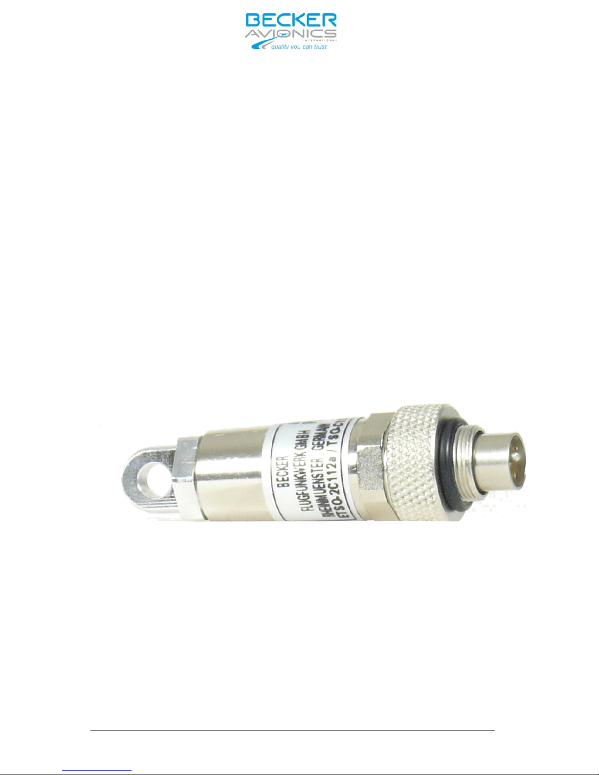
Pict. 1: External Memory EM6100-(XXX)
The EM6100-(XXX) is the memory device (optional). It is a small device connected to the IC6100 and
stores all sy
stem configuratio
n parameters.
It
allows a quick field replacement of the IC6100 without
reconfiguration when replacing by a new IC6100.
1.3.3 Memory device EM6100-(XXX)
Page 9

DV 64480.DIC.01 Issue 1 Sep./2013
Page
1-5
IC6100
1.4 Identification of article
1.4.1 Types of Intercom Amplifier Unit
Intercom Amplifier Unit
IC 6100 -X-(XX)
1
2
Standard Configuration
Custom Configuration
0
1
EM6100-(XXX) is used
No EM6100-(XXX)
2 Equipped with 2 MIC/HEAD Boards
(operating with up to 4 Headset)
3 Equipped with 3 MIC/HEAD Boards
(operating with up to 6 Headset)
Identification number
IC Amplifier Unit
Page 10

Page
1-6
DV 6 4480.DIC .01 Issu e 1 Sep./2013
IC6100
1.5 Technical data
1.5.1 Power supply
Supply voltage (Bus) I
27.5 V DC nominal
18.0 V DC emergency
Supply voltage (Bus) II 27.5 V DC nominal
18.0 V DC emergency
Back-up voltage (Bus) 27.5 V DC nominal
18.0 V DC emergency
Current consumption (with 6 ACU’s) peak 3.0 A
average 1.5 A
1.5.2 Monitoring
1.5.2.1 Fixed inputs
Number
Sensitivity Channel 1....3
Sensitivity Channel 4....6
6
5 … 40 V adjustable (by software)
2.5 …
20 V
adjus
table (by
software)
600 Ω balanced / floating
≥ 70 dB
Impedance
Crosstalk attenuation between inputs
Muting during transmission
≥ 80 dB
1.5.2.2 Alert tone activation inputs
Number
Function
Input Current
8
active Low, ≤ 1.5 V
≤ 1 mA
Input
No.
Alert
tone
1
2400 Hz
continuous
2
1600 Hz
pulsed
3
2400 Hz
pulsed
4
3840 Hz
pulsed
5
1200
intermittent
6
2133
intermittent
7
3200
intermittent
8
4800
intermittent
Page 11

DV 6 4480.DIC .01 Issu e 1 Sep./2013
Page
1-7
IC6100
1.5.3 Headphone Amplifier
–
Up to 6 ea.
Output power
250 mW (8.66 V) into 300 Ω or
500 mW into 8 Ω
or 2 x 250 mW into 2 x 8 Ω
balanced transformer output,
ungrounded
Distortion
≤ 2.5 % at 1 kHz
Frequency response
Signal-to-noise ratio
Main volume control range
300 Hz … 6 kHz (0/–3 dB)
≥ 70 dB
0 … -48 dB
2400 Hz
1600 Hz , 2400 Hz, 3840 Hz,
1200 Hz, 2133 Hz, 3200 Hz, 4800 Hz,
1600 Hz / 1200 Hz intermittent
1.5.4 Aural tone Generator
Continuous tone
Pulsed tones
Intermittent tones
Service tone 1 (Intercom request)
Service tone 2 (Emergency call
2400 Hz / 800 Hz / 1200 Hz intermittent
Pulsed means
Intermitted means
T
ON
= T
OFF
= 0.5
sec. 3 pulses 0.17sec, repetition rate 2.5 sec
active LO, ≤ 1.5 V
Activation (alert tone control lines)
Input current
≤ 1 mA
Page 12

DV 6 4480.DIC .01 Issu e 1 Sep./2013
Page
1-8
IC6100
50 … 400 mV nominal
150 Ω
12 V DC
1.5.5 Mike / AGC
1.5.5.1 Mike / AGC input (standard carbon mike)
Feed resistance
390 Ω
0.5 … 4 mV nominal
Sensitivity
Impedance
Excitation voltage (idle mode)
1.5.5.2 Mike input (Dynamic mic.)
Sensitivity
Impedance
20 Ω balanced / floating
1.5.5.3 Automatic Gain Control (AGC)
AGC threshold (adjustable)
80 … 150 mV (standard mike)
0.2 … 1 mV (dynamic mike)
Output regulation (∆ ue = +20 dB)
≤ +2 dB
1.5.5.4 Sidetone for IC
Sidetone level
0 dB... -15 dB selectable by SW
step 3 dB, standard - 6 dB
1.5.5.5 CVR connection
Channel 1 (Pilot)
Output voltage
Impedance 5 kΩ
Channel 2 (Copilot)
Output voltage
Impedance 5 k
Mike signal: 800 mV -1 dB / +3 dB
Headphone signal: -3 dB ref. Mike
Natural Mike + Headphone
Mike signal: 800 mV -1 dB / +3 dB
Headphone signal: -3 dB ref. Mik
e
Natural Mike + Headphone
Page 13
Page 1-9
DV 6 4480.DIC .01 Issu e 1 Sep./2013
IC6100
6
Active LO, ≤ 1.5 V
1.5.5.6 Control Inputs
(Discretes) Number
Activation
Input current
1 mA
Input No. Function
1 Winchmann VOX- level selection
2 Intercom request activation (1600 Hz / 1200 Hz intermitted)
3 Winchmann Volume level selection
4 Alert tone cancellation
5 SELCALL / Third intercom circuit activation
6
Emergency call activation (2400 Hz / 800 Hz / 1200 Hz intermitted
1.5.5.7 Control outputs (discretes)
Number
Switch action
Switch capability
4
Active LO
27.5 V DC / 500 mA
Output No. Function
1 Not used
2 Cockpit CALL indication
3 Cabin CALL indication
4 3rd- IC-Circuit activation
1.5.5.8 Back-Up
monitor Number
Switch action
Normal Mode Output
1
Open contact 27.5 V / 500 mA
1.5.5.9 DC-output
DC output
27.5 V / 500 mA
Page 14

DV 6 4480.DIC .01 Issu e 1 Sep./2013
Page 1-10
IC6100
1.5.6 Intercom operation
Number of participants
up to 6 clients directly connected (Can be
extended up to 12: 2 parallel HS at each port)
VOX threshold (adjustable by SW) 10 … 100 mV (standard mike)
50 … 500 µV (dynamic mike)
0.25 … 3 sec, adjustable
≤ 2.5 % at 1 kHz
300 Hz … 6 kHz (0/-3 dB)
≥ 60 dB
775 mV / 0 dBm
600 Ω (must be terminated at all times)
VOX hold time
Distortion
Frequency response
Signal-to-noise ratio
Input / output voltage on IC-Ring audio lines
Input / output impedance of IC-Ring audio lines
IC switch-off attenuation
Intercom circuits
Call activation
≥ 80 dB
cockpit-cabin / 3rd IC-Circuit / IC-Ring
discrete input
Call indication optical (CALL LED) and acousti-
cal ( 1600 Hz / 1200 Hz intermitted)
and discrete output
1.5.7 Build In Test Equipment (BITE)
1.5.7.1 Power On BuiId In Test (PBIT)
automatically after Power On
Activation
Coverage IC and EM6100 if
connected
Controllers and memories Aural
tone generator Headphone and
speaker Amps. Power supply
Duration
max. 5 sec.
1.5.7.2 Continuous Build In Test
(CBIT) Activation
Permanently active coverage
controllers and data transfer
Page 15

Page
1-11
DV 6 4480.DIC .01 Issu e 1 Sep./2013
IC6100
1.5.7.3 Build In Test Representation
The last 10 IBit results are stored in a non volatile memory and can be read out with the configuration
software. Its scope is mainly for technical repair and maintenance.
- manually activated
using external switch
1.5.7.4 Back-up operation -
Automatically activated
upon supply busses failure or
defection of internal power supply or
processor failure
Headset 1 - FIX 1, Headset 2- FIX 2
Fixed at 50%
Fixed input
Intercom level Headset 1, Headset 2
CVR level
Fixed at 50%
1.5.8 Programming mode Interface
1.5.8.1 Programming mode Interface
CAN Bus
1.5.9 Mechanical data
Length
Length
Width
Height
Weight
Mounting Case Material
338.50 mm ( IC6100-X-(XX) )
379.00 mm ( IC6100-X-(XX) )
57 mm
195 mm
≤ 3 kg
ATR Fixture, Weight < 500 g
AIMg, black
D-Sub 50-pin male shift lock
19pol male
Subminiatur 5-pole female
1.5.10 Unit connectors 2
pieces with Locking devices 1
piece bajonet
1 piece EM6100-(XXX))
- Connectors are coded against inadvertent misconnecting.......
Page 16

DV 64480.DIC.01 Issue 1 Sep./2013
Page 1-12
IC6100
1.5.11 Environmental qualification (EUROCAE/RTCA
ED-14D/
DO-160E)
Environmental qualification for Intercom Amplifier Unit
Characteristic
ED-14E/DO-160E
Section Category Condition
Temperature / Altitude
4.0
D1
Low Ground Survival Temperature
4.5.1
D1
-55° C
Low Operating Temperature
4.5.1
D1
-40° C
High Ground Survival Temperature
4.5.2
D1
+85° C
High Short-Time Operating Temperature
4.5.2
D1
+70° C
High Operating Temperature
4.5.3
D1
+55° C
In-Flight Loss of Cooling
4.5.4
X
no auxiliary cooling required
Altitude
4.6.1
D1
50,000 ft.
Temperature Variation
5.0 B 5 °C per minute
Humidity
6.0 B 48 h at 65 °C at 95 % RH
Shock
7.2 B 6g in all directions
Crash Safety
7.3 B 20g shock; 20g accelaration
Vibration 8.0 S
U M G
Explosion Proofness
9.0
X
Water Proofness
10.0 X Fluids Susceptibilities
11. 0
X
Sand and Dust
12.0
X
Fungus Resistance
13.0 X Salt Spray
14.0
X
Magnetic Effect
15.0 Z less than 0.3 m
Power Input (DC)
16.0 B Voltage Spike
17.0
A
Audio Frequency Conducted Susceptibility
18.0
B
Induced Signal Susceptibility
19.0
AC
Radio Frequency Susceptibility
20.0
WR
Emission of RF
21.0
M
Lightning Induced Transient Susceptibility
22.0
A3E3X
Lightning Direct Effects
23.0
X
Icing
24.0
X
Electrostatic Discharge (ESD)
25.0
A
Fire Flammability 26.0 X
1.6 Software
All data for IC Amplifier Unit are stored in the IC6100 itself and EM6100, if connected. If control elements on
the SW are altered, a data transmission immediately takes place to the IC Amplifier Unit. Saving the current
configuration is necessary for permanent validation. The software was classified as level C in accordance with
EUROCAE / RTCA document ED-12B / DO-178B.
Page 17

Page 1-13
DV 64480.DIC.01 Issue 1 Sep./2013
IC6100
1.7 Approvals
- FAA
1.8 Scope of delivery
for operation with External memory device EM6100-(XXX)
1.9 Accessories (not contained in the scope of delivery)
- Mounting MT519-1 mod.1 for IC6100-X-(XX) Article-No.: 0890.790-261
- External memory device EM6100-(XXX) Article-No.: 0608.270-921
- Service Cable Kit 1K6100 Article-No.: 0608.750-276
Connector Kit CK 5101-C
consisting of:
- 19-pol. cable connector, crimp
- 50-pol. cable connector (2 ea.required)
- Crimp Coding pins ( 2 ea. required)
- Connector housing
- Two (2) Resistor metal film 121 Ohm
Article-No.: 0615.889-954
Article-No.: 0586.870-954
Article-No.: 0794.279-277
Article-No.: 0774.421-277
Article-No.: 0782.211-277
Article-No.: 0575.933-277
Article-No.: 0717.762-323
Option:
Article-No.:
0614.981-954
Connector Kit CK 5103-C (Manufacturer Commital)
consisting of:
CSW6100-2
configuration
software set
consisting of:
- CAN - USB
-Adapter
- Code Meter Stick
Manuals
-
19-pol. cable connector, crimp
- 50-pol. cable connector (2 ea.required)
- Crimp Coding pins ( 2 ea. required)
- Connector housing
- Two (2) Resistor metal film 121 Ohm
Article-No.: 0615.005-277
Article-No.: 0774.421-277
Article-No.: 0782.211-277
Article-No.: 0575.933-277
Article-No.: 0717.762-323
Article-No.:
0608.602-919
- EASA
TSO-C139
ETSO-C139 (Pending)
Article-No.: 0925.702-921
Article-No.: 0925.703-921
- IC6100-2 (XX) Digital Intercom Unit (for max. 12 users)
- IC6100-3 (XX) Digital Intercom Unit (for max. 12 usesr)
Article-No.: 0900.149-071
Article-No.: 0900.150-071
- Installation and Operation DV 64480.DIC.01
- Maintenance and Repair DV 64480.DIC.02
Page 18

Page
1-14
IC6100
BLANK
DV 64480.DIC.01 Issue 1 Sep./2013
Page 19

Page 2-I
IC6100
Table of Contents
Section 2 INSTALLATION Page
2.1
2-1
2.1.1
2-1
2.2
2-1
2.3
2-1
2.4
2-1
2.5
2-2
2.5.1
2-2
2.6
2-3
2.7
2-5
2.8
2-6
2.8.1
General
Remark for the Intercom Amplifier Unit version IC6100-X-(110)
Inspection before installation
Continued Airworthiness
Mechanical installation
Aircraft wiring
General
Dimensions Intercom Amplifier Unit
Location of connectors
Connector Pin assignments
P1 - P2 D-Sub 50-pol. male, shift-lock connector
2-6
2.8.2
2-7
2.8.3
2-7
2.8.4
2-8
2.9
2-8
2.10
2-8
2.10.1
2-8
2.10.2
2-9
2-10
2-11
2.10.3
2.10.4
Fig. 2-1
2-3
Fig. 2-2
2-4
Fig. 2-3
2-5
Fig. 2-4
2-6
Fig. 2-5
2-8
Fig. 2-6
2-9
Fig. 2-7
2-10
Fig. 2-8
2-11
Installation dimensions (measures in mm)
Mounting Intercom Amplifier Unit
Physical locations of connectors
Logical pin assignment
Power connections
Audio and CVR connections
Fix audio and IC ring connections
Interwiring diagram Control and other connections
DV 64480.DIC.01 Issue 1 Sep./2013
Becker-Bus System, B-Bus connector
Address coding for J5 (IC)
Pin connections of the unit connector J6 (EM6100-(XXX))
Configuration software
Interwiring diagrams
Interwiring diagram Power connections
Interwiring diagram Audio and CVR connections
Interwiring diagram Fx audio and IC ring connections
Interwiring diagram control and other connections
Page 20

Page 2-II
IC6100
BLANK
DV 64480.DIC.01 Issue 1 Sep./2013
Page 21

Page
2-1
IC6100
Section 2 INSTALLATION
2.1 General
The installation of the Intercom Amplifier Unit depends on the type of aircraft and its equipment and
therefore only general information can be given in this section.
Notice:
Changes or modifications made to this equipment not expressly approved by Becker Avionics,
Inc. and/ or Becker Flugfunkwerk GmbH may void the authorization to operate this
equipment.
2.1.1 Remark for the Intercom Amplifier Unit version IC6100-X-(XX)
If the memory device EM6100-(XXX) is replaced by a new one, it is important to be aware that the configuration data from the existing
IC6100 will be overwritten by the factory default data stored in the
memory device EM6100-(XXX).
2.2 Inspection before installation
Before installing the Intercom Amplifier Unit in an aircraft, carry out a visual inspection for any damage,
paying particular attention to the following:
- Dirt, dents, scratches, corrosion, broken attaching parts on the housing and housing parts.
- Dirt and scratches on the identification plate, front panel and marking.
- Dirt, bent or broken pins, cracked connector inserts.
- Missing screws.
- Bended pins.
2.3 Continued Airworthiness
Maintenance of the Intercom Amplifier Unit is “on condition” only. Periodic maintenance of this
products is not required.
2.4 Mechanical installation
The Intercom Amplifier Unit is designed for installation in the avionics compartment of an aircraft
or helicopter. The dimensional details are given in Fig. 2-1.
DV 64480.DIC.01 Issue 1 Sep./2013
Page 22

Page
2-2
IC6100
2.5 Aircraft / Helicopter wiring
2.5.1 General
The plug and socket connection is shown from Fig. 2-5 to Fig. 2-11. The following points are to be observed for the wiring :
a. Only cable fit for aviation (self-extinguishing) shall be used. AWG 20 for power supply and AWG 24
for other cables.
b. The interface lines are each to be laid as 2-core twisted and screened (AWG 24) cables.
c. Every single cable harness of a unit connector must have separate screening.
d. Rubber sleeves are to be fitted over the soldering points on the unit connector.
e. A fuse or circuit breaker should be fitted in the power supply of the Intercom Amplifier Unit.
f. No RF cable should be included in the cable harnesses. Laying connecting cables together with ca-
bles which cary AF power or impulses is to be avoided.
g. Check the wiring carefully before switching on the units, particularly that (UB+) and (GND) have not
been mixed up.
DV 64480.DIC.01 Issue 1 Sep./2013
Page 23

Page
2-3
IC6100
2.6 Dimensions IC Amplifier
Unit
Fig. 2-1
Installation dimensions (measures
in mm)
DV 64480.DIC.01 Issue 1 Sep./2013
Page 24

Page
2-4
IC6100
Fig. 2-2 Mounting Tray for
IC Amplifier Unit
DV 64480.DIC.01 Issue 1 Sep./2013
Page 25

Page 2-5
IC6100
2.7 Location of connectors
Fig. 2-3 Physical location of connectors
DV 64480.DIC.01 Issue 1 Sep./2013
Page 26

Page
2-6
DV 64480.DIC.01 Issue 1 Sep./2013
IC6100
2.8 Connector Pin assignments
Fig. 2-4 Logical pin assignment
Pin
Signal
17 50 34 1
Pin Signal
17
HS)1)Mic)in)HI HS1 33 18 1 HS)2)Mic)in)HI
16
HS)1)Mic)in)LO 16 HS1 49 35 2 2 HS)2)Mic)in)LO
33
HS)1)Mic)in)SH 32 HS1 19 18 HS)2)Mic)in)SH
49 HS)1)Phone)out)HI 15 48 36 3 35 HS)2)Phone)out)HI
48 HS)1)Phone)out)LO HS3 31 20 36 HS)2)Phone)out)LO
32
HS)1)Phone)out)SH 14 HS3 47 37 4 19 HS)2)Phone)out)SH
15
HS)3)Mic)in)HI 30 HS3 21 3 HS)4)Mic)in)HI
14
HS)3)Mic)in)LO 13 46 38 5 4 HS)4)Mic)in)LO
31
HS)3)Mic)in)SH HS5 29 22 20 HS)4)Mic)in)SH
47
HS)3)Phone)out)HI 12 HS5 45 39 6 37 HS)4)Phone)out)HI
46 HS)3)Phone)out)LO 28 HS5 23 38 HS)4)Phone)out)LO
30
HS)3)Phone)out)SH 11 44 40 7 21 HS)4)Phone)out)SH
13
HS)5)Mic)in)HI CVR1 27 24 5 HS)6)Mic)in)HI
12
HS)5)Mic)in)LO 10 1/2)SH 43 41 8 6 HS)6)Mic)in)LO
29
HS)5)Mic)in)SH 1/2)Com 26 25 22 HS)6)Mic)in)SH
45
HS)5)Phone)out)HI 9 42 42 9 39 HS)6)Phone)out)HI
44
HS)5)Phone)out)LO CVR2 25 26 40 HS)6)Phone)out)LO
28
HS)5)Phone)out)SH 8 41 43 10 23 HS)6)Phone)out)SH
11
CVR1)out 24 27 7 CVR1)out
9
CVR2)out 7 40 44 11 9 CVR2)out
10
CVR1/2)Common 23 28 8 CVR1/2)Common
27
CVR1/2)Shield 6 39 45 12 24 CVR1/2)Shield
8
Control)In)1 22 29 10 Control)In)2
7
Control)In)3 5 38 46 13 11 Control)In)4
6
Control)In)5 21 30 12 Control)In)6
5
IC)RING)LINE 4 37 47 14 13 IC)RING)LINE
4
IC)Ring)GND 20 31 14 IC)Ring)GND
1
BU)Monitor 3 36 48 15 17 BU)Monitor
37
FIX)IN)2)HI 19 32 47 FIX)IN)1)HI
36
FIX)IN)2)LO 2 35 49 16 48 FIX)IN)1)LO
20
FIX)IN)2)SH 18 33 31 FIX)IN)1)SH
3
FIX)IN)4)HI 1 34 50 17 15 FIX)IN)3)HI
2
FIX)IN)4)LO 16 FIX)IN)3)LO
19
FIX)IN)4)SH 32 FIX)IN)3)SH
35
FIX)IN)6)HI 49 FIX)IN)5)HI
34
FIX)IN)6)LO 50 FIX)IN)5)LO
18
FIX)IN)6)SH 33 FIX)IN)5)SH
43
HotMike)1 41 HotMike)2
42
HotMike)3 42 HotMike)4
41
HotMike)5 43 HotMike)6
40
HotMike)7 44 HotMike)8
39
BU)DC)IN 45 BU)DC)IN
38
DC1)IN)27.5V)+ 46 DC2)IN)27.5V)+
21
DC1)IN)GND)))
n
30 DC2)IN)GND)))
n
50
CODING)PIN 34 CODING)PIN
26
Control)Out)1 25 Control)Out)1
25
Control)Out)2 26 Control)Out)2
24
Control)Out)3 27 Control)Out)3
23
Control)Out)4 28 Control)Out)4
22
DC)Out) 29 BU)DC)GND)
P1
P2
2.8.1 IC6100 P1 and P2 connector Pin assignments
P1 - P2 D-Sub 50-pol. male, shift-lock connector
Page 27

DV 64480.DIC.01 Issue 1 Sep./2013
Page
2-7
IC6100
2.8.2 Becker-Bus System, B-Bus connector
P5 Souriau, Typ 851-02 E14-19 P50, shell 14, 19-polig. Bayonet
Pin Signal
name
Remark
L Dev Address Bit
0
M Dev Address Bit
1
A Dev Address Bit
2
B Dev Address Bit
3
U Reset
out
V
Reset
in
N
Address
GND
C BB1-HI-in
D BB1-LO-in
P BB1-SH-in
E
BB1-HI-out
F
BB1-LO-out
R BB1-SH-out
G BB2-HI-in
H BB2-LO-in
S BB2-SH-in
J BB2-HI-out
K
BB2-LO-out
T
BB2-SH-out
2.8.3 Address coding for J5 (IC)
Address
Unit Bit 0 (Pin L)
Bit 1 (Pin M)
Bit 2 (Pin A)
Bit 3 (Pin B)
0000
IC
connect to
GND
connect to
GND
connect to
GND
connect to
GND
The addresses for the IC device is set by connecting the pins L, M, A, B to ground or left open.
This is achieved in the cable-plug.
Page 28

Page
2-8
DV 64480.DIC.01 Issue 1 Sep./2013
IC6100
2.8.4 Pin connections of the unit connector J6 (EM6100-(XXX))
The unit connector type is subminature 5-pole female.
Pin Pin
Name
Pin
Description
1 VCC Power
supply
2
I2C CLK
Clock
3
Not
connected
Reserved
4
I2C DAT
Data
5 GND Power supply
return
2.9 Configuration software
The configuration of the DVCS 6100 can be changed by using a Personal Computer or Laptop and
Configuration Set CSW6100-X.
2.10 Interwiring diagrams
2.10.1 Interwiring diagram Power connections
Fig. 2-5 Power connections
Page 29

DV 64480.DIC.01 Issue 1 Sep./2013
Page 2-9
IC6100
2.10.2 lnterwiring diagram Audio and CVR connections
Fig. 2-6 Audio and CVR
connections
Page 30

Page 2-10 DV 64480.DIC.01 Issue 1 Sep./2013
IC6100
2.10.3 lnterwiring diagram Fix audio and IC ring connections
Fig. 2-7 Fix audio and IC ring
connections
Page 31

DV 64480.DIC.01 Issue 1 Sep./2013
Page 2-11
IC6100
2.10.4 lnterwiring diagram Control and other connections
Fig. 2-8 Control and other
connections
Page 32

Page
2-12
DV 64480.DIC.01 Issue 1 Sep./2013
IC6100
BLANK
Page 33

DV 64480.DIC.01 Issue 1 Sep./2013
3-I
IC6100
Table of Contents
Section 3 Operation Page
3.1 3-1
3.2
3-1
3.3
3-1
3.4
3-1
3.4.1
3-1
3.4.2
3-1
3.4.3
3-2
3.4.4
3-2
3.4.5
3-2
3.4.6
3-2
3.4.7
3-2
3.4.8
3-3
3.4.9
3-3
3.4.10
3-3
3.4.11
3-3
3.4.12
3-6
3.5 3-7
General Description
Configuring the IC Amplifier Unit
External Memory EM6100-(XXX)
Control Functions
Headset
Sidetone
Fix Input Channels (Warning audio tones)
Cockpit Voice Recorder Output CVR
Alert tones
Signal tones
Discrete Activation Signals
Other discrete Activation Inputs
Winchman operation
Discrete Outputs for Indications
Intercom Circuits
Backup mode
Service Connector
3-4
3-5
3-6
3-7
3-8
Fig. 3-1 Intercom Circuits (Standard Configuration)
Fig. 3-2 Intercom Circuits (Third Circuit for special mission operation)
Fig. 3-3 Aural Alert Tone Inputs
Fig. 3-4 Service Connector inside the aircraft
Fig. 3-5 Service Connector with the service cable kit SCK6100-1
Page 34

3-II
DV 64480.DIC.01 Issue 1 Sep./2013
IC6100
BLANK
Page 35

DV 64480.DIC.01 Issue 1 Sep./2013
Page
3-1
IC6100
Section 3 OPERATION
3.1 General Description
Information in this section consists of functions and operations for the IC Amplifier Unit.
The IC Amplifier Unit does not have any operator accessible controls.
All settings and adjustments to the operating parameters are made by the Configuration Software
CSW6100-X. For more information refer to the CSW-Software manual.
The IC Amplifier Unit is the core unit of the audio system and therefore the central connecting
point for all Headsets and audio inputs. The IC Amplifier Unit enables intercommunication
functions. All user headsets are connected to the IC Amplifier Unit.
Ten (10) internal signal tones can be activated by discrete signal from external. Eight signal tones
can be used as alert tones and configured with priority. Some other controls and indications are
possible. A detailed description will follow in the next sections.
3.2
Configuring the IC Amplifier Unit
A PC can be connected via CAN BUS interface with the IC Amplifier Unit. The individual operator
settings for control, specified from the operation requirements, can be configured by the Configuration
Software CSW6100-X.
3.3 External Memory EM6100-(XXX)
The EM6100-(XXX) is the memory device (optional). It is a small device connected to the Remote Elec-
tronic Unit and stores all system configuration parameters. It allows a quick field replacement of the Re-
mote Electronic Unit without reconfiguration of the
IC6100 on the bench.
3.4 Control Functions
3.4.1 Headset
The IC Amplifier Unit supports six headsets with dynamic or standard microphones. The sensitivity of
the microphone input and
the level of the phone output can be configured. Up to 12 headsets are
possible to be connected, 2 in parallel at each HS port.
3.4.2 Sidetone
The
IC Amplifier Unit can be configured for sidetone. The sidetone level can be adjusted in 3 dB steps
from 0 dB to -15 dB.
Page 36

Page
3-2
DV 64480.DIC.01 Issue 1 Sep./2013
IC6100
3.4.3 Fix Input Channels (Warning audio tones)
The Intercom Amplifier Unit supports three direct input channels with input sensitivity adjustable from
5V – 40 V, and three direct input channels with input sensitivity adjustable from 2.5V – 20V under
main volume control.
Note!
FIX INPUT-Channels and Alert tones selectable with CSW6100 software for every user.
3.4.4 Cockpit Voice Recorder Output CVR
The Intercom Amplifier Unit supports two Cockpit Voice Recorder outputs for the combined mike and
phone signal, one from Pilot and the other from Copilot.
3.4.5 Alert Tones
The Intercom Amplifier Unit provides eight predefined alert tones. Each tone can be activated by a discrete input signal (Low active). All type of tones are listed in section 1 paragraph 1.5.2.4 in this manual.
A separate discrete input can be used to cancel the warning tones by an external switch.
Note!
For special mission operation some Alert tone activation input must be spend alternatively for
other operations!
In case of special mission configuration some alert tone activation inputs can be used for other functions:
• Alert tone 1, just this use.
•
Alert tone 2 for 3rd Intercom Circuit isolation control. This input isolates all users assigned to the
3rd IC - Circuit by the configuration software.
• Alert tone 3 to 8 for 6 IC Hot Mike Keys (headset without ACU configuration).
3.4.6 Signal tones
The IC Amplifier Unit supports two signal tones. One is the Intercom Request signal and the other is the
E-Call signal. Both signals can be enabled or disabled by the configuration.
3.4.7 Discrete Activation Signals
The IC Amplifier Unit supports external switches to be used to activate the signal tones for Intercom
Request and Emergency Call.
Page 37

Page
3-3
DV 64480.DIC.01 Issue 1 Sep./2013
IC6100
3.4.8 Other discrete Activation Inputs
The IC6100 supports a selective call activation input. This input can be enabled or disabled by the
configuration. Its function will be similar that of the Alert tone 2 input control line.
3.4.9 Winchman operation
The Winchman functionality can be assigned to any headset port without installed physical ACU by the
configuration setup. With one external
push buttons the VOX level can be remotely controlled by the
Winchman operator.
By pressing one external push buttons the winchman function will be activated. This enables
the winchman to increase the VOX threshold level for his headset. The external push buttons in the
winchman work area (connected via discrete input lines) is mounted separately (near the cabin door).
3.4.10 Discrete Outputs for Indications
The Intercom Amplifier Unit supports output for the “Cockpit Call”, “Cabin Call” and the 3rd IC-circuit
disconnect indication.
• “Cabin Call” and “Cockpit Call” (Control OUT 2 and 3): active LO.
If "IC Request Call" (Control input line 2) is activated momentarily, the Cockpit call line will be solid LO
and Cabin CALL will be intermittent LO. If Control IN 6 (E-Call) is activated momentarily, will happen the
opposite.
• ”Third IC-Circuit isolated” (Control Out 4): active LO, if the Alert Tone 2 input line is activated momentarily.
3.4.11 Intercom Circuits
The Intercom Amplifier Unit supports 3 intercom Cir
cuits.
1. Cockpit-Cabin Crew.
2. 3rd IC-circuit (has to be controlled by an external switch).
3.
IC-Ring Line (connected to the Cabin-Cockpit or 3rd intercom circuit; configurable by the CSW Software).
Two of the Intercom Circuits (Cockpit and Cabin) can be directly controlled by the Audio Control Unit.
Page 38

DV 64480.DIC.01 Issue 1 Sep./2013 Page
3-4
IC6100
Examples:
a) Standard Configuration:
Fig. 3-1 Intercom Circuits (Standard Configuration)
Page 39

DV 64480.DIC.01 Issue 1 Sep./2013 Page
3-5
IC6100
c) Third Circuit for special mission operation:
Fig. 3-2 Intercom Circuits (Third Circuit for special mission operation)
Special configurations for Intercommunication:
a) Operation “Headset without ACU”
Operators can use headsets without Audio Control Unit. The adjustment of IC Volume and VOX
Threshold, can be configured by the CSW - Software.
.
Page 40

Page
3-6
DV 64480.DIC.01 Issue 1 Sep./2013
IC6100
c) Operation ”3rd IC - Circuit”
Any headset in the Cockpit or Cabin Circuit and the IC-Ring line can be assigned to the 3rd IC
- Circuit. This function must be enabled by the CSW - Software.
Note!
If the function 3
rd
IC-Circuit is active, the below fig: 3-4 shows alternative the alert tone (Tone 2) which
has to be used for disconnection. Therefore the previous alert tone is not longer available.
Table indicates the alternative use of alert tones activation inputs:
Remark
Alternative
IC-KEY
see Note
1
see Note
2
Special
Functions
see Note
3
1
Alert Tone 1
N/A
N/A
2
Alert Tone 2
N/A
N/A
Third IC
circuit
isolation
3
N/A
4
N/A
5
N/A
6
N/A
7
N/A
8
N/A
Fig. 3-3 Aural Alert Tone Inputs
Alert Tone 3
Alert Tone 4
Alert Tone 5
Alert Tone 6
Alert Tone 7
Alert Tone 8
IC/Headset 1
IC/Headset 2
IC/Headset 3
IC/Headset 4
IC/Headset 5
IC/Headset 6
Headset 1
Headset 2
Headset 3
Headset 4
Headset 5
Headset 6
N/A
Alert
Tone
Input
Note 1:
If the IC HOT MIKE function is used, the above table shows the assignment.
Note:
If the 3rd Intercom Circuit is enabled in CSW, the above table shows the assignment for isolation.
3.4.11 Backup mode
The IC Amplifier Unit supports the Backup mode operation.
In order that the function ”Backup Mode” be available, the IC6100 needs to be connected to an emergency
power source. This c
an be the emergency battery or an emergency power bus. The Connection pins for this
supply voltage are shown in the connector pin assignment of P1 and P2.
Page 41

Page
3-7
IC6100
3.5 Service Connector
Becker Flugfunkwerk GmbH recommend the installation of a service connector. This allows the
configuration of the
Intercom Amplifier Unit after installation inside the aircraft.
a) Service connector inside the aircraft:
For the pinout of the 9 pin DSub connector refer to the Fig. 2-12 in section 2 of this manual.
Fig. 3-4 Service Connector inside the aircraft
DV 64480.DIC.01 Issue 1 Sep./2013
Page 42

Page
3-8
DV 64480.DIC.01 Issue 1 Sep./2013
b) Service cable kit
With the service cable kit SCK6100-1 the configuration of the Intercom Amplifier Unit can be done on
t
est bench.
Fig. 3-5 Service Connector with the service cable kit SCK6100-1
IC6100
Page 43

Page
3-9
DV 64480.DIC.01 Issue 1 Sep./2013
IC6100
BLANK
Page 44

Page
3-10
DV 64480.DIC.01 Issue 1 Sep./2013
IC6100
Fig. 3-6 System diagram with
IC6100
Page 45

Page
3-11
DV 64480.DIC.01 Issue 1 Sep./2013
IC6100
BLANK
 Loading...