

Page 1

Instruction Manual
for
the HPP-5
High Pressure
Positioner
Table of Contents
Section Page
Introduction 2
Description 2
Scope of Manual 2
Technical Assistance 2
Applications 3
Guidelines for usage 3
Technical Information 4
Specifications 4
Materials of Construction 4
Accessories 4
Principals of Operation 5
Close on increasing 5
Open on increasing 6
Adjustment Procedure 7
Deadband Setting 8
Bias Adjustment 9
Range Adjustment 10
Section Page
Changing Positioner Action 12
Conversion to Split Range 13
Assembly Procedures Separate Manual
Inspection Procedures 15
Parts Ordering 16
Parts List 16
Seal Kits 16
Appendix – Parts & Mounting detail
Open on increasing (parts) 18
Close on increasing (parts) 19
Page 2

HPP-4 Positioner
Instruction Manual
Introduction
The Becker HPP-5 series positioner
represents a breakthrough in valve control technology for the natural gas industry. Built to exacting specifications,
the easily maintained unit offers highly
accurate control with excellent control
characteristics in a broad range of operating environments. The HPP-5 series
positioner is designed such that upon
reaching a valve position and achieving
a steady state, the gas consumption is
very low. Additionally, its bleed gas
can be routed to a lower pressure
downstream or fuel gas system, eliminating bleed gas completely. This
means significant savings to your company in terms of minimizing expensive
bleed gas as well as a cost saving
means of minimizing the environmental
impact of atmospheric hydrocarbons
and diminishing natural resources.
Description
The Becker HPP-5 positioner is used in
control valve assemblies with a controller or I/P transducer and double acting
actuator to provide accurate flow or
pressure control. The HPP-5 can be
used with various valve types that utilize
a double acting pneumatic piston actuator. The HPP-5 design positioner
represents Becker’s commitment to
continuos development of new products
and updating of existing products to
maximize their performance while retaining simple operation and minimum
maintenance.
Valves over 16” in diameter require the
use of a Becker HPP-4 positioner with
Volume boosters.
Scope of Manual
This manual provides information on installation, operation, adjustment, and
maintenance of the Becker HPP-5 po-
sitioner. For information concerning actuators, valves, and accessories, refer
to the instruction manuals provided with
the specific product.
Note: Only those qualified through training or
experience should install, operate, or maintain
Becker positioners. If there are any questions
concerning these instructions, contact your
Becker sales representative, sales office, or
manufacturer before proceeding.
Technical Assistance
Should you have any questions, you
may contact your local Becker Precision sales representative or Becker
Precision technical assistance at:
Becker Precision Equipment, Inc.
Attn: Technical Assistance
950 Pratt Boulevard
Elk Grove Village, IL 60007 USA
Toll Free: (800) 323-8844
Tel: (847) 437-5940
Fax: (847) 437-2549
e-mail: becker@bpe950.com
HPP-5 2 September 1999
Page 3

HPP-5 Positioner
Instruction Manual
Applications
• Primary Pressure Control
• Overpressure Protection (Monitor)
• Underpressure Protection
(Standby)
• Relief Valve
• Backpressure Control
• Power Plant Type Applications*
• When Unique "Bleed to Pressure
System" BPS™ feature can be
utilized
• Any large downstream systems
(city gate stations, inter-system
pressure limiting)
• Suction control to reciprocating
compressors*
• Double-stage cut (working monitor regulator*
* (consult Becker for additional information)
Guidelines for Usage
Large Volume Control Valve Actuators:
Control Valves that require large volume
actuators may require Model VB-250
Volume Boosters to ensure adequate
stroking speed. HPP-5 positioners are
NOT compatible with volume boosters.
The HPP-4 positioner must be used
Bleed to Pressure System: The HPP-5
Positioner is typically utilized for applications where no discharge pressure of
less than 350 psig is available. The very
low steady state bleed of the positioner
makes it efficient for minimizing atmospheric emmisions. The HPP-5 is also
compatible with the Becker BPS (Bleed
to pressure system).
High Gain Systems: The HPP-5 is not
preferred for this application. It may be
successfully used with small diameter
(4” and smaller) ball valves for this application, but its limited orifice capacity
makes it too slow for controlling larger
valves on short systems.
CVE Globe Pattern Control Valves: The
Becker HPP series positioners are compatible with the Globe style control valve,
but require a minimum of 2” of actuator
stroke for proper feedback and operation. This makes it impossible to use
this positioner with most globe valves
smaller than 4” port size.
Compatible Actuators:
• Becker RPDA Actuators (Rotary Pis-
ton Double-Acting)
• Becker LPDA Actuators (Linear Pis-
ton Double-Acting)
• Other manufacturer’s double-acting
piston actuators*
*consult Becker for additional informa-
tion
Retrofit Compatibility:
Optimum performance is achieved by
pairing the HPP-5 with genuine Becker
control valve actuators. Should you already have existing control valve actuator
(s) in service, the addition of a Model
HPP-5 can improve performance and
eliminate atmospheric bleed emissions if
using the BPS (Bleed to a pressure system) feature.
Some Compatible Actuators:
• Bettis T-Series Piston Actuators
• Fisher Type 470 Piston Actuators
• Fisher Type 1061 Piston
HPP-5 3 September 1999
Page 4
HPP-5 Positioner
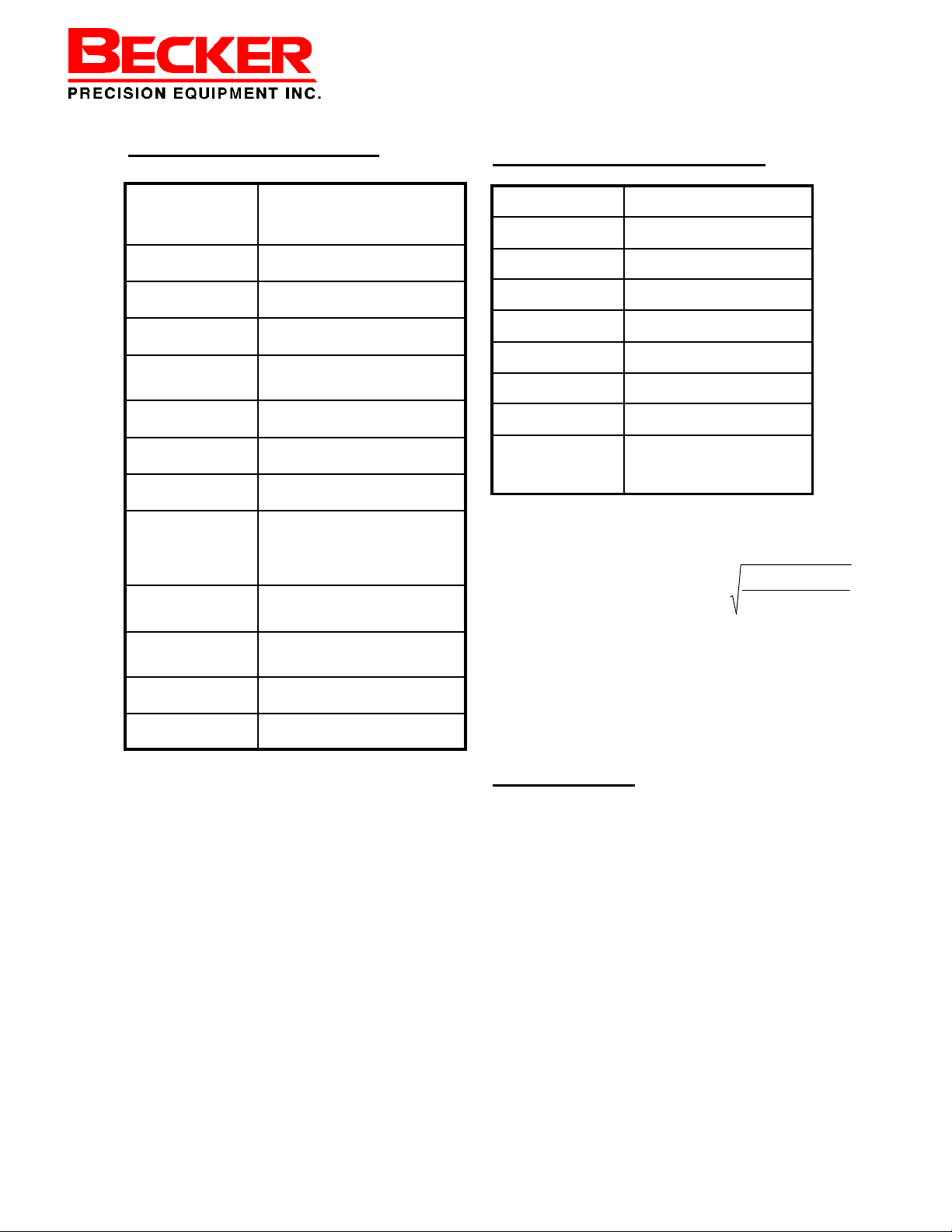
Specifications
Technical Specifications
Input Signal: Standard: 3-15 psi or 6-30 psi.
Output Signal: Pneumatic pressure as required by the
Loss of Signal: Reverse Acting: Open on loss of signal.
Connections: All Ports: ¼” N.P.T.
Action: Direct and Reverse Acting:. Field-
Performance: Resolution: 0.4%*
Flow Capacity: CV = 1.5
Steady State
Consumption:
Power Gas Requirement:
Operative Temperature
Limits:
Housing: Meets NEMA 3 classification (weather
Installation Orientation:
Approximate Weight: 15 pounds.
Adjustable: Zero is adjustable from 230 psig, span is adjustable from 5-24
actuator up to full supply pressure.
Direct Acting: Close on loss of signal.
reversible
Hysteresis: .6%*
Near Zero
Use clean, dry filtered (100 micron)
gas.
Discharging to Atmosphere:
150 psig maximum.
-20 to 160°F
(-28 to 70°C).
tight).
Vertical or horizontal position allowable.
Materials of Construction
External Parts: Anodized 2024 Aluminum
Internal Parts: 316 Stainless Steel and 2024 Ano-
Feedback Lever: 316 Stainless Steel
Range Spring: Plated Music Wire
Diaphragms: Buna-N with Nylon Reinforcement
Seats and O-Rings: Buna-N
Tubing: 316 Stainless Steel
Fittings: 316 Stainless Steel
Gauges: 2 ½” Dial Liquid filled Brass Con-
Maximum Supply Regulator Capacity
Q = 312.86 x P1 x CV x
Q = Min. Supply Regulators Capacity (scfh)
G = Specific Gravity of Gas
T = 460 + Operative Temperature (°F)
Cv = Flow Factor
P
= Supply Pressure to Positioner (psig)
1
dized Aluminum
nection with Stainless Steel Case.
(Stainless Steel connection op-
1
+× TG
460
)(
* Resolution and repeatability figures reflect a
positioner that is adjusted with a minimum deadband to reduce bleed gas. If the deadband is
eliminated (slightly increasing the bleed gas),
resolution and repeatability will improve.
Accessories
• Atmospheric Bleed Control (AB Control):
maintains minimum pressure differential
across the cylinder. The AB Control is required in order to provide the necessary
output to operate the control valve under all
design conditions.
• NBV No Bleed valve – same function as
DPS, no adjustments or tubing required.
Works up to 150 psig power gas.
• DPS Series Non-Bleed Sensor: achieves
non-bleeding conditions in either full open
or full closed positions. Selection based
upon power gas pressure and discharge
gas pressure.
HPP-5 4 September 1999
Page 5
HPP-5 Positioner
“How-It-Works”
Power
Gas
InstrumentSignal
Cylinder
Top
Exhaust
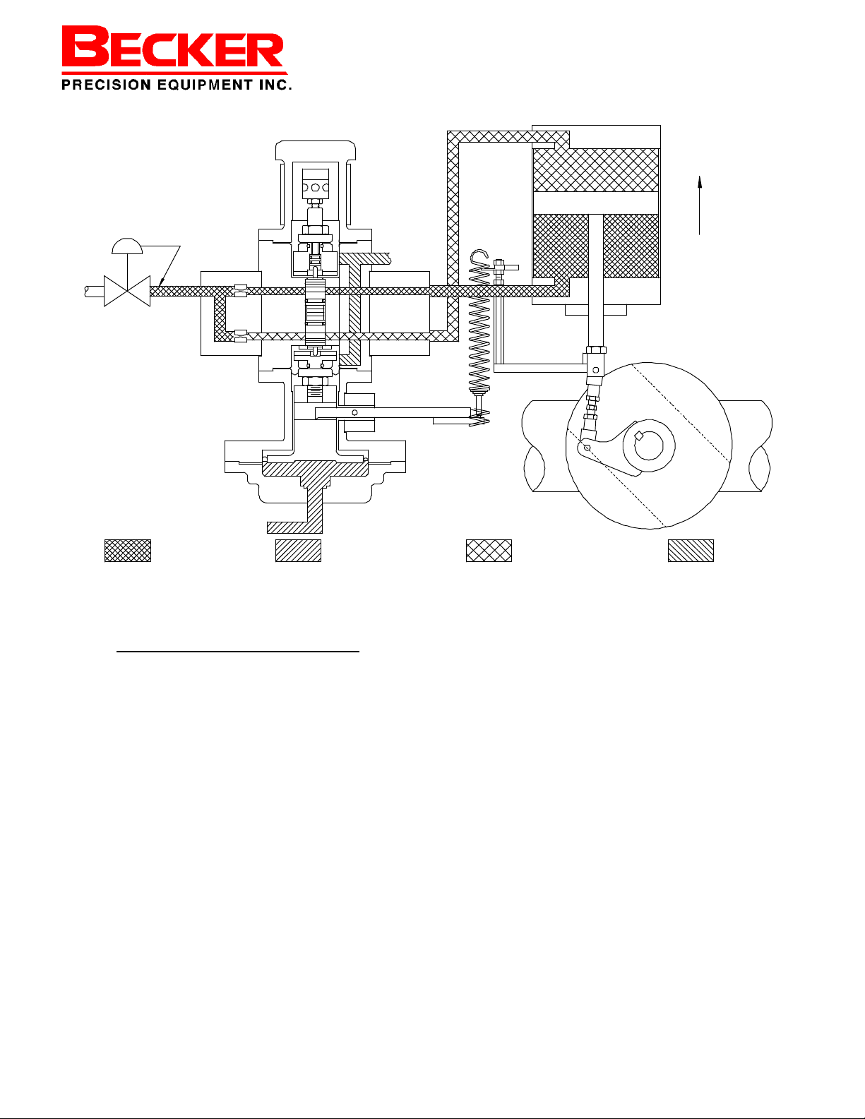
Principles of Operation
Close on Increasing Signal
The positioner is a force-balanced instrument that provides a control valve position proportional to the pneumatic input signal. The control valve will open on loss
of input signal. The energy to operate the control valve is obtained from the differential between the supply and discharge pressures. In steady state, the forces imposed on the balance beam by the input signal diaphragm and the range spring are
equal; therefore, the top and bottom balance valves in the positioner are at or near
their closed positions. The cylinder top and bottom pressures are both equal to
power gas pressure, and the control valve is stationary. An increase in the input
signal pressure results in the opening of the lower balanced valve due to an imbalance in the beam forces. This decreases the pressure in the cylinder top., while
the pressure in cylinder bottom remains at power gas. The control valve begins to
close. The actuator rod stretches the range spring, increasing its tension. This
force, which opposes the force on the balanced beam caused by the increasing input signal, continues to increase until the balance beam forces are in equilibrium.
At this point the valve is in the correct position for the applied input signal. The positioner has a sensitivity adjustment which permits a balance between greater accuracy (from a smaller deadband) and minimal bleed gas.
HPP-5 5 September 1999
Page 6
HPP-5 Positioner
“How-It-Works”
Power
Gas
InstrumentSignal
Cylinder
Top
Exhaust
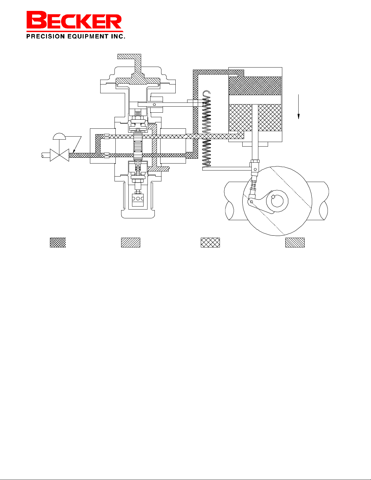
Open on increasing Signal
The positioner is a force-balanced instrument that provides a control valve position proportional to the pneumatic input signal. The control valve will close on loss of
input signal. The energy to operate the control valve is obtained from the differential
between the supply and discharge pressures. In steady state, the forces imposed
on the balance beam by the input signal diaphragm and the range spring are equal;
therefore, the top and bottom balance valves of the positioner are at or near their
closed positions. The cylinder top and bottom pressures are both equal to power
gas, and the control valve is stationary. An increase in the input signal pressure results in the the opening of the upper balance valve due to an imbalance in the beam
forces. This decreases the pressure in the cylinder bottom, while the pressure in
the cylinder top remains at power gas pressure. The control valve begins to open.
The actuator rod stretches the range spring, increasing its tension. This force, which
opposes the force on the balanced beam caused by the increasing input signal, continues to increase until the balance beam forces are in equilibrium. At this point the
valve is in the correct position for the applied input signal. The positioner has a sensitivity adjustment which permits a balance between greater accuracy (from a
smaller deadband) and minimal bleed gas.
HPP-5 6 September 1999
Page 7

HPP-5 Positioner
Adjustment Procedures
Your HPP-5 positioner will come factory
adjusted for your particular application.
The use of the adjustment procedures
will be necessary upon installation of a
rubber goods replacement kit or any
other disassembly or reassembly of
the positioner.
Adjustment Procedure
The sensitivity adjustment drum on one
end of the positioner determines the
sensitivity of the unit.
The variable orifices determine the
stroking speed of the positioner.
Initial Adjustment
1. Adjust the supply regulator:
Adjust the supply regulator to the desired Power Gas pressure. Refer to the
original invoice paperwork supplied
with the product for the appropriate
Power Gas pressure setting. It is imperative that adequate supply gas pressure be supplied to the VRP-CH in order to ensure proper operation of the
system and all accessories.
Table A – Exhaust vented to Atmosphere
SUPPLY
PRESSURE
(psig)
4 5 6 8 10 12 14
VARIABLE ORIFICE NUMBER
2. Adjust the adjustable orifices:
The adjustable orifices are utilized to
control the volume of gas that is supplied to the HPP-5.
The stroking speed of the system is
proportional to the numerical value of
the adjustable orifice. Adjustable orifice settings are typically equal for both
orifices. However, a few applications
may require unequal settings for each
adjustable orifice. Refer to Fine Tuning
for more information on utilizing unequal adjustable orifice settings. Set
both orifices according to the table below.
Notes:
• To determine the cylinder bore, look
at the model number stamped on
the stainless steel tag on the top of
the cylinder. The cylinder bore will
be the first number following the first
capital letter “H”. This one or two
digit number following the first “H”
will be the diameter in inches and
will be followed by another letter
(For example, a unit with the model
number 6H8F6FG-H4 has an
CYLINDER BORE (IN.)
Up to 50 3 3 3 4 4 5 6
51-200 2 2 3 3 4 5 5
201-600 2 2 2 3 3 4 5
Table B – Exhaust vented to Pressure System
SUPPLY
PRESSURE
(psig)
Up to 50 3 3 3 4 4 5 6
51-200 4 4 4 5 5 6 6
201-600 2 2 2 3 3 4 5
HPP-5 7 September 1999
4 5 6 8 10 12 14
CYLINDER BORE (IN.)
VARIABLE ORIFICE NUMBER
Page 8

HPP-5 Positioner
Adjustment Procedures
Deadband Setting
1. Turn the deadband adjustment drum
in the direction of increasing the
numbers until the drum can no
longer turn. Then turn the adjust-
ment drum one full turn in the oppo-
site direction (use the numbers on
the drum as a guide).
2. If not already attached, wind 3-4
coils of the range spring onto the re-
tainer.
3. If not already adjusted, set the bias
adjustment screw in the middle of
its travel range.
4. Apply power gas to the HPP-5 posi-
tioner
5. Set the instrument signal pressure
at the midpoint of its range (e.g.. 9
psig for a 3-15 psig range, 18 psig
for a 6-30 psig range). Allow the ac-
tuator to stroke the valve to an inter-
mediate position and the gauge
pressures to balance. (if the valve
does not stroke, insure that the po-
sitioner is communicating with the
actuator cylinder. If equipped with
an MCV-3, make sure the MCV-3
left handle is in automatic.
6. If the actuator is equipped with an
MCV-3 Manual Control Valve), place
the left MCV-3 handle in the manual
position. If the actuator is not
equipped with an MCV-3, use the
block valve (1/4 “ ball valve) installed
between the positioner output and
the actuator. Once the actuator has
reached its desired position (based
on the mid-signal applied to the instrument port – Step 5), place the
block valve in the closed position.
7. Final Sensitivity Drum Adjustment
For positioner’s bleeding to atmosphere:
Disconnect any bug vent or tube fitting
from the exhaust port.
Turn the deadband adjustment drum in
the direction of decreasing numbers,
until the exhaust port begins to bleed
gas. Than turn the drum in the opposite direction until the exhaust port just
stops bleeding.
The unit is properly adjusted if increasing or decreasing the input signa by .2
psig causes the cylinder top and bottom gauges to develop differential
equal to at least 20% of power gas.
Replace the exhaust fitting
For Positioner’s bleeding to a pressure system:
Slowly decrease the setting of the
deadband (decreasing numbers) until
both cylinder gauges are equal and
read 90 to 95% of power gas pressure.
Signal Line from Control-
HPP-5 8 September 1999
Page 9

HPP-5 Positioner
Bias Adjustment
Note: When increasing or decreasing
the instrument signal, the output pressure should swing up and down. When
changing direction of the false instrument signal, the output pressure should
immediately reverse direction. Any
“bump” or initial reaction of the gauge in
the wrong direction indicates friction
(requiring the unit be rebuilt to eliminate
the friction).
8. Place the instrument signal to automatic and open the block valves or
return the left handle of the MCV to
automatic.
Span Adjustment
Spring Lock
Balanced Beam
Proportional Topworks
Bias Adjustment
Bias Lock Nuts (Qty. 2)
Spring Retainer
Bias Adjustment
For Standard (Non-split range) Systems:
1. To increase the bias setting, increase tension on the range spring.
This is accomplished by either raising the spring retainer or screwing
the bias adjustment stud into the indicator bar or tail rod. Note the two
jam nuts tightened against one another to adjust the length of the
stud. When properly adjusted,
tighten the bias lock nut(s).
2. In order to decrease the bias setting, decrease tension on the range
spring by either lowering the spring
retainer or screwing the bias adjustment stud out of the indicator bar or
tail rod. Note the two jam nuts tightened against one another to adjust
the length of the stud. When properly adjusted, tighten the bias lock
nut(s).
For Split Range Systems (see Table 1 )
3. Find the bias adjustment screw (1/220 thread with 3/8 flats) on the end
of the positioner opposite the pneumatic signal input port. Loosen the
jam nut located on the adjustment
screw.
4. To increase the bias setting, tighten
the adjustment screw.
5. To decrease the bias setting, loosen
the adjustment screw.
6. Holding the adjustment screw in
place, tighten the jam nut against
the positioner body.
HPP-5 9 September 1999
Page 10

HPP-5 Positioner
Range Adjustment
Spring Range
Green (20-2592) 1-6
Silver (25-1038) 2-11
Blue (25-1036) 4-20
Red (25-1037) 8-30
Table 1: Adjustable Bias Springs
Spring Range
Stroke (Part Number)
(psi)
4 6 8 12
6
12
18
24
01-6288 01-6287 01-6287 01-6801
25-1151 25-1152 25-1153 25-1154
25-1599 25-1600 25-1601 25-1602
25-1218 25-1219 25-1220 25-1221
Table 2: Range Spring Configurations
Note: For intermediate ranges, use the next
size range spring.
Range Adjustment
Note: There will be some interaction between
range and bias adjustments. It may therefore
be necessary to readjust the bias and re-check
the range after completing the following steps.
The range, or the amount of travel between the lower and upper limits of the
input signal, is set with the range
spring. This range will typically be 12
psi for a 3-15 psi system or 24 psi for a
6-30 psi system. The limits of the range
can be defined as the initial point at
which the instrument signal
to the HPP-5 starts valve
movement until the end of
the valve stroke and full
pressure differential across
the cylinder output gauges.
1. After setting the bias for
the start of the valve travel,
continue increasing the in-
strument signal until the
valve strokes is completed AND the
cylinder output gauges show full
power gas pressure differential.
2. Be sure not to overshoot at this
point as any signal level above this
upper limit will show the same reading on the cylinder gauges. This
point is the highest end of the range
and the value may not necessarily
be equal to the desired upper range
value.
HPP-5 10 September 1999
Page 11

3. If the range is less than desired (i.e.
the actuator reaches its full travel in
less than the specified input range),
strengthen the range spring by
winding it counterclockwise onto
the spring retainer. If the range is
greater than desired, weaken the
range spring by winding it clockwise. Repeat adjustments until the
desired range provides full or zero
output pressure.
4. If the desired range is not achieved
after making the above adjustments, readjust the bias (per the
previous instructions) to allow
proper range adjustment.
5. It may be necessary to change the
range spring retainer for some nonstandard ranges (refer to Table 3).
HPP-5 Positioner
Range Adjustment
Type Typical Use
Short (01-2509 ) 8” and 12” Stroke
Intermediate (11-2572 ) 6” Stroke
Long ( 01-2042 ) 4” Stroke
Table 3: Range Spring Retainer
HPP-5 11 September 1999
Page 12

HPP-5 Positioner
Positioner Action
Changing Action of Positioner
To change the positioner from open on increasing signal to close on increasing signal, or vice versa, the following parts kits
must be ordered:
To change open on increasing to close on
increasing: Part #25-1444 plus an Exten-
sion Rod (item #13 in drawing 35-0516,
see Table 4). The serial number of the actuator must be specified. The exact part
number of the extension rod will vary
based on the actuator stroke.
To change close on increasing to open on
increasing: Part #25-1289. Note: If con-
verting a close on increasing signal positioner to open on increasing signal, the
wide end of the tube (item #9) may be
shortened by 11/16" with a hack saw in
place of ordering part #25-1289.
The stroke length of the actuator cylinder
MUST be specified when ordering the
above part numbers. If the actuator serial
number cannot be found, the stroke length
can be found in the regulator model number. The stroke length is the first letter after the "H" in the model number. For example model 10H12L6FG-SR-S-HSB40/35-100-O has a stroke length of "L", or
12 inches ["L" is the 12th letter in the alphabet]).
Refer to the drawings 35-0515 and 350516 in the Appendix for the following:
1. Disconnect all supply lines, instrument
line, and output line from the positioner.
2. Remove the range spring (item #4) at
both ends and those items connecting
it to the rod (item #23) and the posi-
3. Remove the positioner from the
bracket (item #18). The tubing and
fittings on each side of the positioner
must be taken off and installed in the
opposite corner from their original position (see piping schematic provided
by Becker Precision Equipment) then
reattached to the positioner. This will
allow the positioner to maintain the
actuator failure mode when the positioner is turned upside down.
4. Move the bracket assembly (item
#18), tube assembly (items #16 and
#17), and cover plate (item #11) to
the positions shown on the desired
drawing.
5. Install the positioner in the opposite
of its original position (upside down if
it was right side up, right side up if it
was upside down).
6. Using parts from the factory kit, as-
semble the spring and surrounding
hardware according to the drawing of
the desired configuration. (Note: all
original parts may not be used when
converting from close on increasing
to open on increasing).
7. The entire bracket assembly (item
#18) or the outer angle may need to
be turned upside down to accommodate the new spring height.
8. Reconnect the supply, instrument,
and output lines according to piping
schematic supplied.
Note: The flow direction must be maintained through the positioner bodies
when re-piping. (I.e. the flow [supply or
exhaust] moves from P1 to P2 and P3 to
HPP-5 12 September 1999
Page 13

Stroke With Without
4
6
8
25-8265 25-8001
25-8136 25-1093
25-1402 25-1423
Table 4: Extension Rods for Positioners to
Close on Increasing Signal
Conversion to Split Range
Converting a standard positioner to a
split range positioner (pneumatic input
other than 3-15 psi or 6-30 psi), requires
ordering the proper conversion kit from
the factory. This kit will include a bias
spring and bias spring cartridge. If required, it will also contain a new range
spring and mounting spacers.
1. For close on increasing positioner:
Remove the cap on the top of the positioner along with the spring inside
it.
For open on increasing positioner:
Remove the mounting bracket holding the cap on the bottom of the positioner. Then remove this cap along
with the spring inside it.
2. Replace the cap and spring with the
larger bias spring cartridge and bias
spring found in the kit. Make sure
the bias adjustment screw in the
bias spring cartridge is snug against
the bias spring and the spring is cen-
tered before tightening the spring
cartridge.
3. For open on increasing positioner:
Remove the washer and jam nut from
the adjusting screw in the bias spring
HPP-5 Positioner
Split Range
3. (Cont.) Reattach the mounting
bracket upside down from its original
position.
4. Slide the thread spacer (brass
bushing) over the adjusting screw
and tighten the washer and jam nut
against the thread spacer.
5. If a range spring was sent with the
kit, remove the existing range spring
and replace it with the new one.
6. Adjust the unit per the Adjustment
Procedures.
Stroke Close on
Increasing
4” 25-6014 25-1464 Proportional:
6” 25-6014 25-1465 Proportional:
8” 25-6014 25-1466 Tailrod:
Table 5: Split Range Conversion Kits
Note: Refer to Table 1 and Table 2 for
Bias and Range Spring part numbers.
Open on
Increasing
Reference
Drawings
35-0513
35-0313/A
35-0511
35-0511/A
Tailrod
Mount:
35-0522
HPP-5 13 September 1999
Page 14

HPP-5 Positioner
Maintenance and Inspection
Maintenance and Inspection
As with all precision equipment, it is
necessary to periodically test the positioner to ensure optimum performance.
We recommend the following procedure once a year.
1. Shut off supply pressure and bleed
down at positioner. Note the settings of the variable orifices and remove them from the orifice assembly. Clean them thoroughly and reinstall using new o-rings, being sure
to install each orifice in the same
hole from which it was removed (the
orifice and block have matching
numbers for this purpose). Reset
orifices to original settings. Turn on
supply pressure.
2. Apply a midrange signal to the positioner. Allow the control valve to become stationary at about 50% of the
range. Close the cylinder block
valves or move the MCV-3 handle to
the manual position. The positioner
is now isolated from the cylinder.
Apply a ± ¼ PSIG signal change.
Observe the response in the output
gauges. The output pressure
should develop differential pressure
equal to 20% of the power gas pressure. If the output pressure does
not show immediate response, the
positioner may have too much deadband. Reduce the deadband by
turning the drum in the direction of
decreasing numbers. If the pressures do not respond in the correct
direction when reversing the instrument signal change, the unit has internal friction. Disassemble the unit
and replace all rubber goods.
3. Check the integrity of the balanced
3. (Cont.) Check the integrity of the
balanced valve seats by increasing
the dead band by 1 full number.
When the cylinder top and bottom
gages are equal to the power gas,
the exhaust port should not exhibit
any bleed gas. If either of these
tests fail, then the positioner is not
properly adjusted or the unit needs
to be reassembled with new rubber
goods.
4. Soap test around all diaphragm interfaces, orifice assemblies and
vents. If any leaks are found around
the diaphragms, refer to the assembly instructions for replacement of
all internal rubber parts.
5. Observe the operation of the
gauges. If any gauges are defective,
replace them.
6. Check range and bias. If necessary, readjust per Adjustment Procedures.
Should problems arise or more information is required, call toll free (800)
323-8844 for assistance
HPP-5 14 September 1999
Page 15

HPP-5 Positioner
Maintenance and Inspection
Model HPP-5 Single-Acting Positioner Annual Maintenance Checklist
1. __________ Soap test all diaphragm mating surfaces to check for leaks.
2. __________ Replace rubber goods utilizing Becker Model HPP-4 Single-Acting
Positioner Repair Kit (Part # 30-9501) if necessary.
Refer to Pages 12-17, HPP-SB Assembly Procedures.
3. __________ Confirm Power Gas Supply Pressure is correct.
Refer to original Becker invoice paperwork for proper power gas setting.
4. __________ Observe operation of gages and replace if defective.
5. __________ Check integrity of HPP-4 positioner seats. Varying input signal 1 psig
should send one cylinder output gauge to full power gas.
Refer to Procedure 7 note, pages 9, Adjustment Procedure.
6. __________ Check response of HPP-4 positioner. Varying input signal 1/4 psig
should produce cylinder output gauge differential equal to 40% of
power gas.
Refer to Procedure 6-8, pages 8-9, Adjustment Procedure.
7. __________ Check range and bias of HPP-4 positioner and adjust if necessary.
Refer to Pages 9-11 of adjustment procedure.
8. __________ Inspect and Verify Proper Operation of all HPP-4 Positioner Accesso-
ries.
Refer to technical manual included with each specific instrumentation ac-
cessory for further instruction.
Note: It is not necessary to replace any rubber goods in Becker
instrumentation or instrumentation accessories on a regular basis. However, common
practice suggests that replacement of rubber goods on a 5-year cycle basis provides
adequate preventative maintenance.
HPP-4 15 September 1999 HPP-5 15 September 1999
Page 16

HPP-5 Positioner
Parts List
Parts Ordering
The following is provided to allow the ordering of replacement parts. Please specify the Becker
instrument serial number when ordering parts (this can be found on the Stainless Steel tab attached to the pilot by the 7/16 hex head cap screws. If the instrument was supplied as a complete valve regulator package, the Stainless tag attached to the actuator piston can also provide
the serial number. See Drawing #30-0601
Key Description Part No.
1 Pilot base 30-7005
2 Lexan Cover 25-1034
3 Adjusting Drum 35-1520
4 Washer 25-1016
5 Inside piston 35-1507
6 Orifice Assembly 35-1015
7 Seat Cover 35-1519
8 1/2-20 Jam Nut 98-3056
9 Beam Adjusting Drum 25-1124
10 Diaphragm 25-1213
11
12
13 1/8 Roll Pin SS 98-2950
14 8-32 x 1” SHCS 98-3144
15 Beam Block 25-1086
16 Outside piston 25-1018
17 3/16 x 1/2 Roll Pin SS 98-3089
Key Description Part No.
29 Pilot Post S.S. 35-1521
30 Double pilot Body 35-1504
31 Valve Adjusting Screw 35-1517
32 Balance valve assembly 35-1510
33 Seat assembly 01-7082
34 S.S. Control tag 25-1061
35 10-32 x 3/8 FHMS 98-2684
36 #10 Lockwasher 98-3178
37 Strainer for Balance valve 35-1559
38 Seat Spacer 35-1526
39 Beam 25-1084
Seal Kit
A seal kit containing diaphragms, orings, and seats, for the HPP-5 positioner is available directly from Becker.
Simply contact Becker Precision Equipment and order part number 30-9501
18 1/4-20 x 2-1/2 HHCS 98-3180
19 Gauge Manifold 35-1013
20 O-Ring –012 95-2615
21 1/4-28 Jam Nut 98-3214
22 Diaphragm w/ Convolute 25-1027
23 Beam Spacer 30-7055
24 1/4-20 x 1” HHCS 98-2579
25 3-15 pressure cartridge 25-1082
26 5-40 x 1/4 SHCS 98-2629
27 1/4-20 x 3/4 SHCS 98-3137
28 8-32 x 1/2 SHCS 98-2614
HPP-5 15 September 1999
Page 17

HPP
-
5 Positioner
Parts List
HPP-5 17 September 1999
Page 18

HPP-5 Positioner
Appendix
HPP-5 18 September 1999
Page 19

HPP-5 Positioner
Appendix
HPP-5 19 September 1999
 Loading...