

Page 1

HazardControl
HC520
en
Assembly and Operating Instructions
Escape route control unit for the second
emergency route
Important information for:
• Fitters / • Electricians / • Users
Please forward accordingly!
These instructions must be kept safe for future reference.
4007 630 030 0d25/09/2019
Becker-Antriebe GmbH
Friedrich-Ebert-Straße 2-4
35764 Sinn/Germany
www.becker-antriebe.com
Page 2

Table of contents
General ................................................................................................... 3
Warranty ................................................................................................. 3
Safety instructions ................................................................................... 4
Intended use ........................................................................................... 5
Device overview ....................................................................................... 6
Wiring ..................................................................................................... 7
Explanation of functions ........................................................................... 9
Setting and function of the DIP switches ...................................................10
Setting the limit positions without connecting to the control unit..................11
Maintenance ..........................................................................................12
Technical data ........................................................................................12
What to do if...?.......................................................................................13
Simplified EU declaration of conformity.....................................................14
Handover report for the customer ............................................................15
Handover report for the installing company ...............................................17
2-en
Page 3
General
The control unit, delivered ex works, controls a DC tubular drive automatically
or via external drive commands. The control unit offers the opportunity of
automatically raising the shading solution in the event of power failure, due to
a fire, for example.
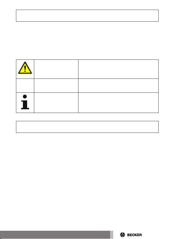
Explanation of pictograms
CAUTION
ATTENTION
CAUTION indicates a hazardous situation
which, if not avoided, could result in injury.
ATTENTION indicates measures that must
be taken to avoid damage to property.
Denotes user tips and other useful information.
Warranty
Structural modifications and incorrect installation which are not in accordance
with these and our other instructions can result in serious injuries, e.g., crushing of limbs. Therefore, structural modifications may only be carried out with
our prior approval and strictly in accordance with our instructions, particularly
the information contained in these Assembly and Operating Instructions.
Any further processing of the products which does not comply with their intended use is not permitted.
The end product manufacturer and fitter have to ensure that all the relevant
current statutory, official and, in particular, EMC regulations are adhered to
during utilisation of our products, especially with regard to end product manufacture, installation and customer advice.
3-en
Page 4
Safety instructions
The following safety instructions and warnings are intended to avert hazards
and to prevent property damage and personal injury.
General information
• Always comply with the regulations of local energy supply companies as
well as the VDE 100 provisions for wet and damp rooms during installation.
• Only use in dry rooms.
• Observe the signal tone for the battery’s change interval
• Only use unmodified original parts from the control unit manufacturer.
• Observe all pertinent country-specific regulations.
• Keep people out of the system’s range of travel.
• If the system is controlled by one or more devices, the system’s range of
travel must always be visible during operation.
• Keep children away from control units.
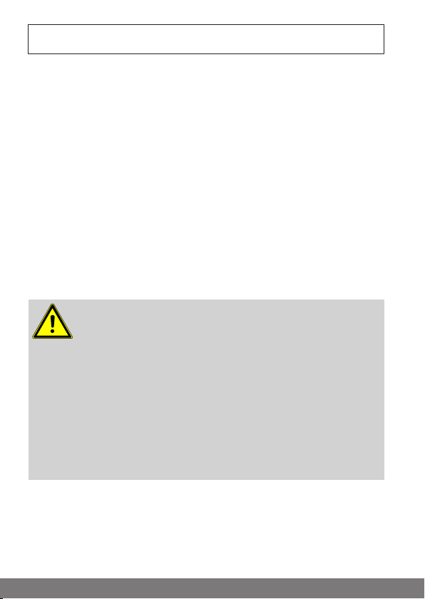
Caution
• Risk of injury due to electric shock.
• The mains connection must be established by a trained
electrician.
• Disconnect the connecting cable from the power supply
prior to assembly.
• When connecting the control cables (protected extra-low
voltages), only use cables with sufficient electric
strength.
• Following commissioning, check that the system is work-
ing correctly in the event of power failure according to the
handover report.
4-en
Page 5

Intended use
The escape route control unit for the second emergency route described in
these instructions is intended for the supply and operation of an M19 model
DC tubular drive from Becker-Antriebe, which can be activated even in the
event of power failure.
Use of the control unit is only permissible for the second escape route and it
must only be used for roller shutters and venetian blind systems.
The use of a two-pole changeover switch as a safety switch is absolutely essential.
The connection of external devices must be carried out in consultation with
specialist retailers.
There are no clear legal requirements regarding the use of battery-buffered
control units in the second emergency route. The manufacturer cannot, therefore, grant generally valid or project-related product approvals for the aforementioned use. The final decision is taken by the respective fire safety authority.
Country-specific special regulations as well as local regulations and guidelines
concerning this matter must be observed and applied under all circumstances.
5-en
Page 6
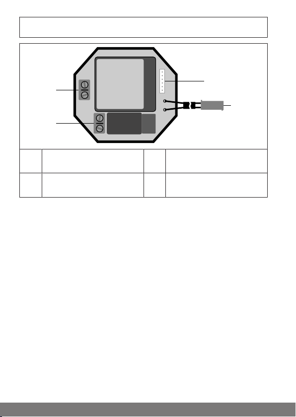
Device overview
1
2
3
4
Connection for individual and
1
central operation
Connection for the battery
2
and the safety switch
Connection for the safety
3
switch and drive
Mains connection
4
6-en
Page 7

Caution
L
N
+
-
M
M
+ -
M
Optional
Battery
Individual operation
(push-button)
Safety switch
Drive
12 V DC
Mains
100–240V AC
50/60Hz
HC520
purple
blue
orange
black
grey
red
Connection:
Control
Connection:
Battery
A B
DC
• Risk of injury due to electric shock.
• Connection may only be performed by a qualified electri-
cian!
• The device only offers back-of-hand protection, not
touch protection.
• Always take into account the device switching current.
Connect the device as follows:
Wiring
7-en
Page 8

After connecting, check that the running direction of the
M
M
+ -
Smoke detector
purple
blue
M
M
+ -
Higher-level control unit
purple
blue
orange
drive is correct. It is irrelevant whether the safety switch is
set "up" or "down". The lettering ("A, B, C, D") in the connection diagram is not shown on the switch and is only used for
reasons of clarity in the figure.
If the shading solution rotates in the incorrect direction, the safety switch connections will need to be swapped around as follows:
• Connections "A" and "B" with incorrect implementation of the function
selected with DIP switch 5 in the event of power failure.
• Connections "C" and "D" with forced opening of the shading solution
when the safety switch is actuated.
Optional possible connection points (central input)
Smoke detector
Higher-level control unit, radio, etc.
8-en
Page 9

Explanation of functions
Automatic opening movement in the event of power
failure
In the event of power failure, the drive automatically raises the shading solution with a battery buffer (can be set using DIP switches). This function is
switched on upon delivery.
Safety switch
If the control unit is no longer functional due to a fire, the escape route can still
be opened in spite of this. When pressed, the safety switch bridges the control
unit, connects the battery directly to the motor and starts the shading solution’s opening movement.
9-en
Page 10

Setting and function of the DIP
ON ON ON ON ON ON
1 2 3 4 5 6
ONOFF
switches
Factory setting: All the DIP switches are set to
OFF.
Switch Position Function
DIP 1
DIP 2
DIP 3
DIP 4
DIP 5
ON Individual operation preferred over central input
OFF Central input preferred over individual operation
ON No alarm message (signal tone)
OFF Alarm message (signal tone) after 1,000 travel cycles
or two years
ON Travel mode until battery discharged in the event of
low battery voltage
OFF Only opening movement possible in the event of low
battery voltage
ON Venetian blind operation (touch mode possible)
OFF Roller shutter operation
ON No action in the event of power failure
OFF The shading solution’s opening movement takes
place in the event of power failure
10-en
Page 11

Switch Position Function
ON No blockage detection
DIP 6
OFF Blockage detection in the DOWN direction with re-
versal
Setting the limit positions without
connecting to the control unit
If the limit positions are to be set before the controller is installed, proceed as
follows:
Connect the tubular drive to the Y plug.
Attention
The tubular drive moves off immediately after connecting to
the battery. Stopping is only possible by disconnecting the
battery.
Connect the battery to the Y plug.
Extend or reduce the range of travel by turning the corresponding set screw
on the tubular drive.
The direction of rotation of the tubular drive can be changed
by swapping the wires at "+" and "-".
11-en
Page 12

Maintenance
We advise replacing the battery and having the system maintained by a specialist company according to the information contained in the handover report
at regular intervals, at the latest every 1,000travel cycles or every two years.
On delivery, the escape route control unit is set using the DIP
switch2 so that an alarm message (signal tone) sounds when
the battery has to be replaced.
Technical data
Type HC520-2600mAh HC520-3000mAh
Rated voltage 100-240 V AC 50/60 Hz
Switching current 5 A / 12 VDC 6.3 A / 12 VDC
Power consumption 1.1VA
Degree of protection IP 20
Class of protection
(dependent on correct assembly)
Permissible ambient temperature 0 to +60 °C
Type of mounting Flush mounted
For rechargeable battery 2600mAh 3000mAh
For tubular drive up to 10Nm 20Nm
0
12-en
Page 13

What to do if...?
Problem Remedy
Drive is not functioning. Check connection.
Check position of safety switch.
Drive is running in the wrong direction.
The control unit does not carry out
the automatic opening movement.
A signal tone sounds. Have battery replaced by a qualified
Drive does not reach the lower limit
position.
Drive only runs in UP direction. Check position of safety switch.
The drive does not carry out the drive
command correctly.
Drive does not stop after detecting a
blockage.
Replace stranded wires for and .
Check DIP switch setting.
Check connection.
Check battery voltage.
electrician.
Check system for an obstacle or
sluggish running.
Check battery voltage.
Check whether a switch has been
used for individual operation instead
of the stipulated push-button.
13-en
Page 14

Simplified EU declaration of
conformity
Becker-Antriebe GmbH hereby declares that this control unit complies with
Directives 2014/30/EU and 2014/35/EU.
The full text of the EU declaration of conformity is available at the following
web address:
www.becker-antriebe.com/ce
Subject to technical changes without notice.
14-en
Page 15

Handover report for the customer
ON ON ON ON ON ON
1 2 3 4 5 6
ON
OFF
The installing company hereby confirms that the following work and functions
have been carried out and checked.
• Connection of the escape route control unit according to these instruc-
tions.
• Two-pole changeover switch installed as a safety switch.
• Drive’s running direction for individual operation and, if necessary, op-
tionally connected devices checked.
• Drive’s battery mode checked in the event of power failure.
• Correct execution of the function selected with DIP switch 5 checked in
the event of power failure.
• Shading solution’s forced opening movement checked when the safety
switch is pressed.
• The system was installed in a proper and functional manner. All the func-
tions, particularly the safety opening movement, were performed by the
customer.
• By way of their signature, the user confirms that the system is working
correctly and was handed over properly.
• DIP switch settings upon handover. Please indicate the position of the
DIP switches with a tick:
Date, name, address and signature: Specialist company
15-en
Page 16

16-en
Page 17

Handover report for the installing
ON ON ON ON ON ON
1 2 3 4 5 6
ON
OFF
company
The installing company hereby confirms that the following work and functions
have been carried out and checked.
• Connection of the escape route control unit according to these instruc-
tions.
• Two-pole changeover switch installed as a safety switch.
• Drive’s running direction for individual operation and, if necessary, op-
tionally connected devices checked.
• Drive’s battery mode checked in the event of power failure.
• Correct execution of the function selected with DIP switch 5 checked in
the event of power failure.
• Shading solution’s forced opening movement checked when the safety
switch is pressed.
• The system was installed in a proper and functional manner. All the func-
tions, particularly the safety opening movement, were performed by the
customer.
• By way of their signature, the user confirms that the system is working
correctly and was handed over properly.
• DIP switch settings upon handover. Please indicate the position of the
DIP switches with a tick:
Date, name, address and signature: Customer
17-en
Page 18

18
Page 19

19
Page 20

 Loading...