

Page 1

Installation and Operation
Manual DV17001.03
VHF Transceiver
VHF Ground Transceiver
GT6201
Issue 06 January 2019
Article-No. 0640.093-071
Becker Avionics GmbH • Baden-Airpark B108 • 77836 Rheinmünster • Germany
+49 (0) 7229 / 305-0 • Fax +49 (0) 7229 / 305-217
http://www.becker-avionics.com • E-mail: info@becker-avionics.com
Page 2
Installation and Operation
Becker Avionics
Contact data for:
Europe, Asia,
Contact data for:
Approved Production and Maintenance Organization
Certificates see: http://www.becker-avionics.com/company-about/ →Certificates
Becker Avionics GmbH
Oceania and
Africa
Baden-Airpark B108
77836 Rheinmünster (Germany)
Tel.: + 49 (0) 7229 / 305-0
Fax: + 49 (0) 7229 / 305-217
Internet: www.becker-avionics.com
Email: info@becker-avionics.com
Customer Service:
Email: support@becker-avionics.com
America,
Australia, Japan
FAILURE OR IMPROPER SELECTION OR IMPROPER USE OF THE PRODUCTS DESCRIBED
HEREIN OR RELATED ITEMS CAN CAUSE DEATH, PERSONAL INJURY AND PROPERTY
DAM AGE.
This document and other information from Becker Avionics GmbH provide product or system options
for further investigation by users having technical knowledge.
The user is responsible for making the final selection of the system and components. The user has to
assure that all performance, endurance, maintenance, safety requirements of the application are met
and warnings be obeyed.
For this the user has to include all aspects of the application to be compliant with the applicable
industry standards and the requirements of the responsible aviation authority. The product
documentations from Becker Avionics GmbH have to be obeyed.
To the extent that Becker Avionics GmbH provide component or system options based upon data or
specifications provided by the user, the user is responsible for determining that such data and
specifications are suitable and sufficient for all applications and reasonably foreseeable uses of the
components or systems.
Term definition: User in the sense of user, installer, installation company.
Becker Avionics Inc
Email: info@beckerusa.com
WARNING - USER RESPONSIBILITY
2 GT6201 DV17001.03 Issue 06 January 2019
Page 3
Becker Avionics
Installation and Operation
Preface
*design depends on variant
*Some figures in this manual are for basic understanding and can be different to the actual design.
Dear Customer,
Thank you for purchasing a Becker Avionics product. We are pleased that you have chosen our
product and we are confident that it will meet your expectations.
For development and manufacturing of our product, the guidelines for highest quality and reliability
have been borne in mind, supplemented by selection of high quality material, responsible production
and testing in accordance to the standards.
Our competent customer support department will respond on any technical question you may have.
Please do not hesitate to contact us at any time.
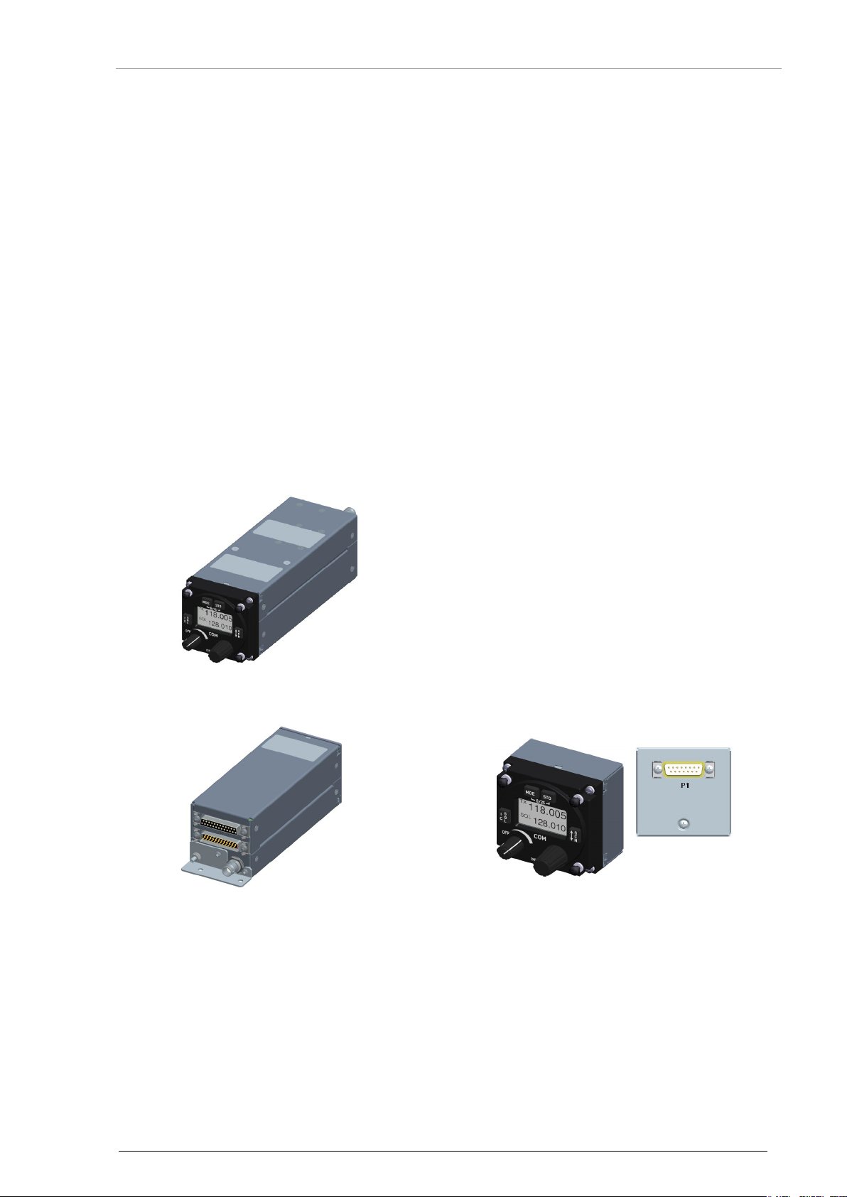
VHF Ground Transceiver*
GT6201
(Single Block Transceiver)
GT6201-XX-R
(Remote-Controlled Transceiver)
RCU6201, RCU6211
(Remote Control Unit)
DV17001.03 Issue 06 January 2019 GT6201 3
Page 4

Installation and Operation
Becker Avionics
List of Effective Pages and Changes
Only technical relevant modifications are described in this table.
Document: DV17001.03 issue 06 Article Number 0640.093-071
Cover Page 01/2019
Introduction 01/2019
Chapter 1 – 5 01/2019
Issue Page No.:
06
1-92 all Changed: Editorial adjustments.
all Added: Information about remote-controlled variant.
-- 1.8 Added: Technical information.
-- 1.8.8 Added: Certification information.
--
--
--
--
--
--
Section /
Chapter
Description
--
--
--
--
--
--
© by Becker Avionics GmbH / all rights reserved
4 GT6201 DV17001.03 Issue 06 January 2019
Page 5

Becker Avionics
Installation and Operation
Table of Contents
1 General Description .................................................................................................................... 11
1.1 Introduction.................................................................................................................................. 12
1.2 Purpose of Equipment ................................................................................................................. 13
1.3 General Notes ............................................................................................................................. 13
1.4 Variants Overview ....................................................................................................................... 14
1.4.1 Software Status ................................................................................................................. 14
1.4.2 Short Description .............................................................................................................. 14
1.5 Scope of Functionality ................................................................................................................. 16
1.5.1 Frequency Indication......................................................................................................... 16
1.5.2 Audio Outputs ................................................................................................................... 16
1.5.3 Mike Inputs ........................................................................................................................ 16
1.5.4 AF Auxiliary Input .............................................................................................................. 17
1.5.5 Sidetone ............................................................................................................................ 17
1.5.6 Squelch Operation ............................................................................................................ 17
1.5.7 Memory Channels ............................................................................................................. 17
1.5.8 Scan Mode ........................................................................................................................ 17
1.5.9 Illumination ........................................................................................................................ 17
1.5.10 LOW BATT Indication ....................................................................................................... 17
1.5.11 Emergency Operation ....................................................................................................... 17
1.5.12 Built-In Tests ..................................................................................................................... 18
1.5.13 Configuration Setup .......................................................................................................... 18
1.5.14 Service Mode .................................................................................................................... 18
1.6 Safety-Conscious Utilization ....................................................................................................... 19
1.7 Restriction for Use ....................................................................................................................... 19
1.8 Technical Data ............................................................................................................................ 20
1.8.1 General Characteristics .................................................................................................... 20
1.8.2 Receiver Data ................................................................................................................... 21
1.8.3 Transmitter Data ............................................................................................................... 22
1.8.4 Emergency Operation ....................................................................................................... 23
1.8.5 Dimensions & Weight........................................................................................................ 23
1.8.6 Software ............................................................................................................................ 24
1.8.7 Hardware .......................................................................................................................... 24
1.8.8 Certifications ..................................................................................................................... 24
1.9 Order Code.................................................................................................................................. 25
1.9.1 GT6201 ............................................................................................................................. 25
1.9.2 RCU62X1 .......................................................................................................................... 25
1.9.3 Accessories ....................................................................................................................... 25
1.9.4 Documentation .................................................................................................................. 25
2 Installation .................................................................................................................................... 27
2.1 Limitations ................................................................................................................................... 28
2.2 Packaging, Transport, Storage ................................................................................................... 28
2.3 Device Assignment ..................................................................................................................... 29
2.3.1 Scope of Delivery .............................................................................................................. 29
2.3.2 State of Delivery ................................................................................................................ 29
2.3.3 Additional Required Equipment ........................................................................................ 29
2.3.4 Type Plate ......................................................................................................................... 30
2.3.5 Software/Firmware Status – Functionality ........................................................................ 30
2.4 Installation Requirements ............................................................................................................ 31
2.4.1 Installation in a Vehicle ..................................................................................................... 31
2.4.2 Rear Panel Installation ...................................................................................................... 31
2.5 Dimensions.................................................................................................................................. 32
2.5.1 GT6201 ............................................................................................................................. 32
2.5.2 GT6201-XX-R ................................................................................................................... 33
2.5.3 RCU62X1 .......................................................................................................................... 34
2.5.4 GT6201, RCU62X1 Rear Panel Installation ..................................................................... 34
2.6 Connector Pin Assignments ........................................................................................................ 35
2.6.1 Antenna Connector (GT6201) .......................................................................................... 35
2.6.2 Grounding Bolt (GT6201) ................................................................................................. 35
2.6.3 Connector P1 (GT6201).................................................................................................... 35
2.6.4 Connector J1 (GT6201) .................................................................................................... 36
DV17001.03 Issue 06 January 2019 GT6201 5
Page 6

Installation and Operation
Becker Avionics
2.6.5 Inputs / Outputs (GT6201) ................................................................................................ 37
2.6.6 Connector Layout RCU62X1 ............................................................................................. 40
2.6.7 Connector P1 (RCU62X1) ................................................................................................. 40
2.6.8 Inputs / Outputs (RCU62X1) ............................................................................................. 41
2.7 Wiring .......................................................................................................................................... 42
2.7.1 Car Cable Harness 1K044 ................................................................................................ 42
2.8 Installation and Configuration ...................................................................................................... 43
2.8.1 Antenna Installation ........................................................................................................... 43
2.9 Configuration Setup ..................................................................................................................... 44
2.9.1 Start Configuration Setup .................................................................................................. 44
2.9.2 Configuration Setup Pages ............................................................................................... 45
2.10 Factory Default Settings .............................................................................................................. 56
2.11 Post Installation Check ................................................................................................................ 59
2.11.1 Mechanical Installation and Wiring Check ........................................................................ 59
2.11.2 Power Supply .................................................................................................................... 59
2.11.3 Receiver / Transmitter Operation ...................................................................................... 59
2.11.4 Antenna Check .................................................................................................................. 59
2.12 Error / Failure Indication .............................................................................................................. 59
2.13 Troubleshooting ........................................................................................................................... 60
3 Operating Instructions ................................................................................................................ 61
3.1 General ........................................................................................................................................ 61
3.2 Device Description....................................................................................................................... 61
3.2.1 Device Assignment ........................................................................................................... 61
3.2.2 Packing, Transport, Storage ............................................................................................. 61
3.2.3 Scope of Delivery .............................................................................................................. 61
3.2.4 Type Plate ......................................................................................................................... 61
3.2.5 Controls and Indications .................................................................................................... 63
3.3 Start-Up ....................................................................................................................................... 64
3.4 Receive Mode .............................................................................................................................. 65
3.5 Transmit Mode ............................................................................................................................. 65
3.6 Frequency Selection Modes ........................................................................................................ 66
3.6.1 Standard Mode .................................................................................................................. 67
3.6.2 Direct Tune Mode .............................................................................................................. 68
3.6.3 Channel Mode ................................................................................................................... 69
3.6.4 Frequency Storage Functions ........................................................................................... 71
3.6.5 Automatic Storage Function .............................................................................................. 72
3.6.6 Scan Mode ........................................................................................................................ 73
3.7 Squelch (SQL) ............................................................................................................................. 73
3.8 RX Field Strength Indication ........................................................................................................ 74
3.9 Channel Spacing Mode ............................................................................................................... 74
3.10 Auxiliary Audio Input (AUX INPUT) ............................................................................................. 75
3.11 Menus .......................................................................................................................................... 75
3.11.1 User Menu ......................................................................................................................... 76
3.12 Warning and Failure Indications .................................................................................................. 77
3.13 Contact Data ................................................................................................................................ 78
4 Certificates ................................................................................................................................... 79
4.1 Certificate Info ............................................................................................................................. 79
4.2 BAF Approval - GT6201 .............................................................................................................. 80
4.3 EC Declaration of Conformity – GT6201-05 ............................................................................... 82
4.4 EC Declaration of Conformity – GT6201-10 ............................................................................... 84
4.5 EC Declaration of Conformity – GT6201-05-R ............................................................................ 86
4.6 EC Declaration of Conformity – GT6201-10-R ............................................................................ 88
4.7 Approval - Telecommunication Office Italy .................................................................................. 90
5 Index .............................................................................................................................................. 92
6 GT6201 DV17001.03 Issue 06 January 2019
Page 7

Becker Avionics
Installation and Operation
List of Figures
List of Abbreviations
AF
Audio Frequency
ATT
Attenuation
AUX
Auxiliary
AWG
American Wire Gauge
BNC
Bayonet Neill Concelman
CBIT
Continuous Built-In Test
CFG
Configuration
CH
Channel, Control Head
COM
Communication
DC
Direct Current
EASA
European Aviation Safety Agency
EMI
Electro Magnetic Interference
ETSI
European Telecommunications Standards Institute
ETSO
European Transmission System Operators
GCM
Chassis Module (ETIS compliant for ground use)
GND
Ground (Vehicle Ground)
HMI
Human Machinery Interface
HIRF
High Intensity Radiated Fields
HW
Hardware
IC
Intercom (not in use for ground applications)
LCD
Liquid Crystal Display
MTBF
Mean Time Between Failure
MTTR
Mean Time To Repair
N/A
Not Applicable
PBIT
Power-On Built-In Test
PTT
Push To Talk
PWR
Power
Figure 1: GT6201 Single Block Transceiver .......................................................................................................... 14
Figure 2: GT6201 Remote-Controlled Transceiver ................................................................................................ 15
Figure 3: RCU62X1 Remote Control Unit .............................................................................................................. 15
Figure 4: Type Plate (Example) ............................................................................................................................. 30
Figure 5: Dimensions: GT6201 Single Block Transceiver ...................................................................................... 32
Figure 6: Dimensions: GT6201-XX-R Remote-Controlled Transceiver .................................................................. 33
Figure 7: Dimensions RCU62X1 (Side View) ......................................................................................................... 34
Figure 8: GT6201, RCU62X1 Front View ............................................................................................................... 34
Figure 9: Drilling Template (Rear-Panel Installation) ............................................................................................. 34
Figure 10: GT6201 – Connector Layout ................................................................................................................. 35
Figure 11: RCU62X1 - Connector Layout .............................................................................................................. 40
Figure 12: Car Cable Harness 1K044 .................................................................................................................... 42
Figure 13: "PASSWORD" ...................................................................................................................................... 44
Figure 14: "DECIVE INFO" .................................................................................................................................... 44
Figure 15: GT6201, RCU62X1: Controls and Indications ...................................................................................... 63
List of Abbreviations
DV17001.03 Issue 06 January 2019 GT6201 7
Page 8

Installation and Operation
Becker Avionics
List of Abbreviations
RSSI
Received Signal Strength Indication
RX
Receive
SQL
Squelch
RSSI
Received Signal Strength Indicator
SPKR
Speaker (Loudspeaker)
SRC
Source
SW
Software
TF
TufLok®, self-locking screws and threads
TX
Transmit
VOX
Voice Operated Switch
VHF
Very High Frequency
VSWR
Voltage Standing Wave Ratio
VU
Volume Unit
Units
A
Ampere
mA
Milliampere
°C
Degree Celsius
cm
Centimeter
dBm
Power Ratio in Decibel referenced to 1 mW
dB
Decibel
g
Gram
Hz
Hertz
kg
Kilogram
kHz
Kilohertz
MHz
Megahertz
mm
Millimeter
Nm
Newton Meter
NM
Nautical Mile (1NM = 1852,0 m)
Ohm (Ω)
Resistance
s
Second
V
Volt
mV
Millivolt
W
Watt
mW
Milliwatt
"
Inch ° Angular degree
Units
8 GT6201 DV17001.03 Issue 06 January 2019
Page 9
Becker Avionics
Installation and Operation
General Safety Definitions
Indicates a hazardous situation which, if not prevented, will result in death or
Indicates a hazardous situation which, if not prevented, could result in death or
Indicates a hazardous situation which, if not prevented, could result in minor or
Is used to address practices not related to physical injury.
Safety instructions (or equivalent) signs indicate specific safety-related
The packaging material is inflammable, if it is disposed of improperly by
The user is responsible for protective covers and/or additional safety measures
serious injury.
serious injury.
moderate injury.
instructions or procedures.
Disposal
burning, toxic fumes may develop.
This product contains materials that fall under the special disposal regulation, which corresponds to
the EC directive for dangerous disposal material We recommend the disposal of such materials in
accordance with the current environmental laws.
• Dispose circuit boards by a technical waste dump which is approved to take on e.g.
electrolytic aluminium capacitors. Do under no circumstances dump the circuit boards with
normal waste dump.
Warranty Conditions
User modifications and changes are not permitted.
Any change made by the user excludes any liability on our part (excluding the work described in this
manual).
• The device must not be opened.
• Do not make any modifications to the device, except for those described in the manual.
• Make connections to the inputs, outputs and interfaces only in the manner described in
the manual.
• Install the devices according to the instructions.
We cannot give any guarantee for other methods.
Conditions of Utilization
General introductory notes
With this device you bought a product which was manufactured and tested before delivery with the
utmost care.
Please take your time to read the notes which you ought to follow closely during installation and
operation.
Otherwise all claims under the warranty will become void and a decreased service life or even
damages must be expected.
in order to prevent damages to persons and electric accidents.
Additional Conditions of Utilization
Please refer to "Safety-Conscious Utilization", page 19.
DV17001.03 Issue 06 January 2019 GT6201 9
Page 10

Installation and Operation
Becker Avionics
Non-Warranty Clause
We checked the contents of this publication for compliance with the associated hard and software. We
can, however, not exclude discrepancies and do therefore not accept any liability for the exact
compliance. The information in this publication is regularly checked, necessary corrections will be part
of the subsequent publications.
10 GT6201 DV17001.03 Issue 06 January 2019
Page 11

Becker Avionics
General Description
Introduction
1 General Description
In this chapter you can read about:
1.1 Introduction.................................................................................................................................. 12
1.2 Purpose of Equipment ................................................................................................................. 13
1.3 General Notes ............................................................................................................................. 13
1.4 Variants Overview ....................................................................................................................... 14
1.4.1 Software Status ................................................................................................................. 14
1.4.2 Short Description .............................................................................................................. 14
1.4.2.1 GT6201 Single Block Transceiver ............................................................................. 14
1.4.2.2 GT6201-XX-R Remote-Controlled Transceiver ........................................................ 15
1.4.2.3 RCU62X1 Remote Control Unit ................................................................................. 15
1.5 Scope of Functionality ................................................................................................................. 16
1.5.1 Frequency Indication......................................................................................................... 16
1.5.2 Audio Outputs ................................................................................................................... 16
1.5.3 Mike Inputs ........................................................................................................................ 16
1.5.4 AF Auxiliary Input .............................................................................................................. 17
1.5.5 Sidetone ............................................................................................................................ 17
1.5.6 Squelch Operation ............................................................................................................ 17
1.5.7 Memory Channels ............................................................................................................. 17
1.5.8 Scan Mode ........................................................................................................................ 17
1.5.9 Illumination ........................................................................................................................ 17
1.5.10 LOW BATT Indication ....................................................................................................... 17
1.5.11 Emergency Operation ....................................................................................................... 17
1.5.12 Built-In Tests ..................................................................................................................... 18
1.5.13 Configuration Setup .......................................................................................................... 18
1.5.14 Service Mode .................................................................................................................... 18
1.6 Safety-Conscious Utilization ....................................................................................................... 19
1.7 Restriction for Use ....................................................................................................................... 19
1.8 Technical Data ............................................................................................................................ 20
1.8.1 General Characteristics .................................................................................................... 20
1.8.2 Receiver Data ................................................................................................................... 21
1.8.3 Transmitter Data ............................................................................................................... 22
1.8.4 Emergency Operation ....................................................................................................... 23
1.8.5 Dimensions & Weight........................................................................................................ 23
1.8.6 Software ............................................................................................................................ 24
1.8.7 Hardware .......................................................................................................................... 24
1.8.8 Certifications ..................................................................................................................... 24
1.9 Order Code.................................................................................................................................. 25
1.9.1 GT6201 ............................................................................................................................. 25
1.9.2 RCU62X1 .......................................................................................................................... 25
1.9.3 Accessories ....................................................................................................................... 25
1.9.4 Documentation .................................................................................................................. 25
This manual describes the Becker VHF-Ground-Transceiver GT6201. The type plate on your device
shows the part number for identification purposes (see "Type Plate
Before starting operation of the device(s) please read this manual carefully, with particular attention to
the description referring to your device(s).
", page 30).
DV17001.03 Issue 06 January 2019 GT6201 11
Page 12

General Description
Becker Avionics
M&R
I&O
General X X
Installation X X
Operation X X
Theory of Operation
X
N/A
Maintenance and Repair
X
N/A
Illustrated Parts List
X
N/A
Modification and Changes
X
N/A
Circuit Diagrams
X
N/A
Certifications X X
Attachments X N/A
Introduction
1.1 Introduction
The technical information in this document applies to the product and variants of GT6201.
• We use also the term GT6201 for descriptions instead writing the complete model
number.
• If a description refers to only one of the product variants its full name is used.
The manuals "Maintenance and Repair" (M&R) and "Installation and Operation" (I&O) contain the
sections:
Section
DV17001.04
DV17001.03
12 GT6201 DV17001.03 Issue 06 January 2019
Page 13

Becker Avionics
General Description
General Notes
1.2 Purpose of Equipment
The VHF-Ground-Transceivers GT6201 are specified for operations on airports, airfields or airline
operation stations.
• The GT6201 is a ground-based equipment made for installation in desk-cabinets,
19-inch racks or cars.
o The GT6201-XX-R variant is a remote-controlled device, which does not include a
control panel. It can receive commands and supplies data through the control unit
RCU62X1 or a third-party controller.
• The GT6201 transceiver can operate with ground power but it is also made for
applications where low power consumption is required.
o GT6201 can operate from standard 14 and 28 VDC installations and from 12 or
24 VDC batteries.
• The GT6201 is for voice communication between ground and airborne stations.
o It uses the band between 118.000...136.9916 MHz respectively 136.9750 MHz
with a selectable channel spacing of 8.33 or 25 kHz.
• The sensitive receiver meets the most recent requirements of ETSI EN 300 676.
• The receiver includes SCAN (dual watch) mode. This is for monitoring of two different
VHF frequency channels at the same time while the communication on the active
frequency is on.
• The GT6201 has a non-volatile memory for the storage of:
o 99 channels with customized labels for storage of VHF frequencies.
o 9 recently selected VHF frequencies are automatically stored.
• The GT6201 is easy to install.
o Installation with four screws (rear panel installation).
o The dimensions correspond to the standard instrument diameter of 58 mm
(2¼ inch).
1.3 General Notes
The word "frequency" is also used in the sense of "channel name", as defined in ICAO Annex 10,
Volume II.
In this document the word "memory channel" or "channel" is also used in the sense of a memory
position identified by a channel number, where a frequency may be stored for later use.
DV17001.03 Issue 06 January 2019 GT6201 13
Page 14
General Description
Becker Avionics
Variants Overview
GT
6201
-
XX
- R
Identifier
Model Number
RF Power Class
05= 6 W RF Power Output
10=
1.4 Variants Overview
10 W RF Power Output
* only available as component with TG660 or for customer specific applications.
1.4.1 Software Status
Description see "Software/Firmware Status – Functionality", page 30.
1.4.2 Short Description
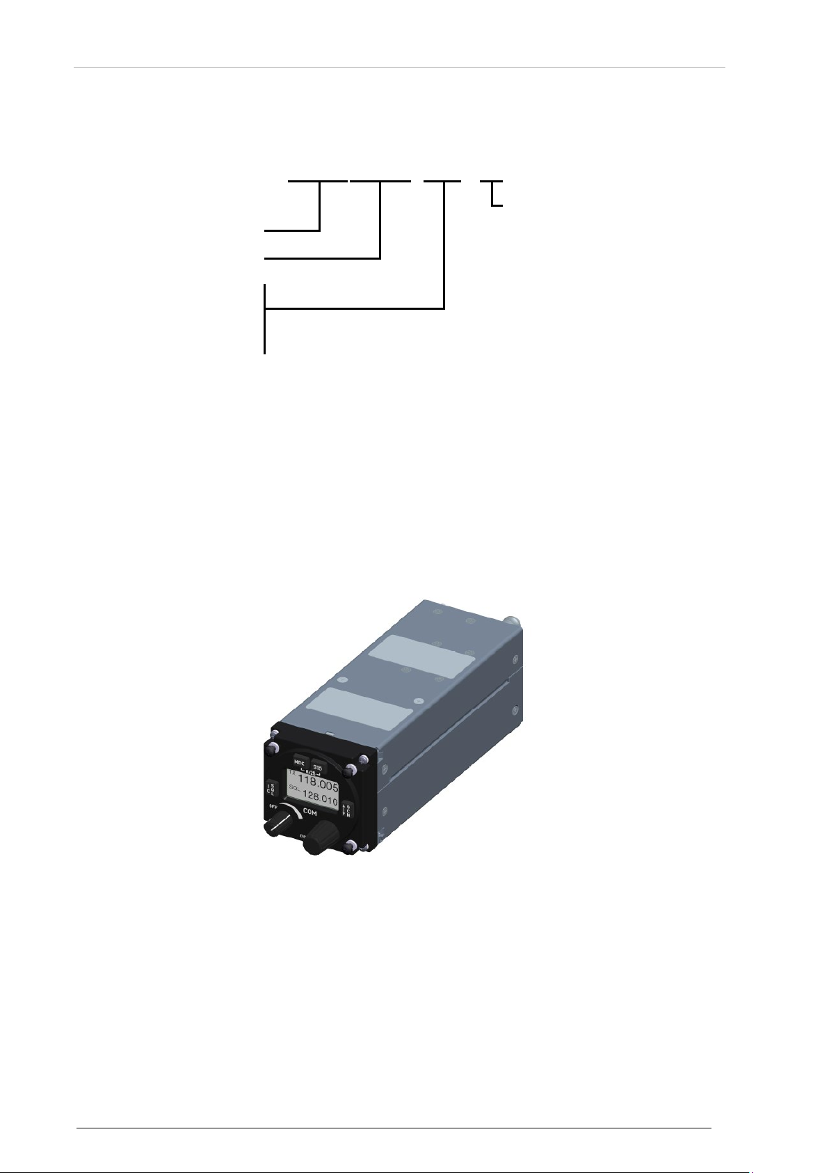
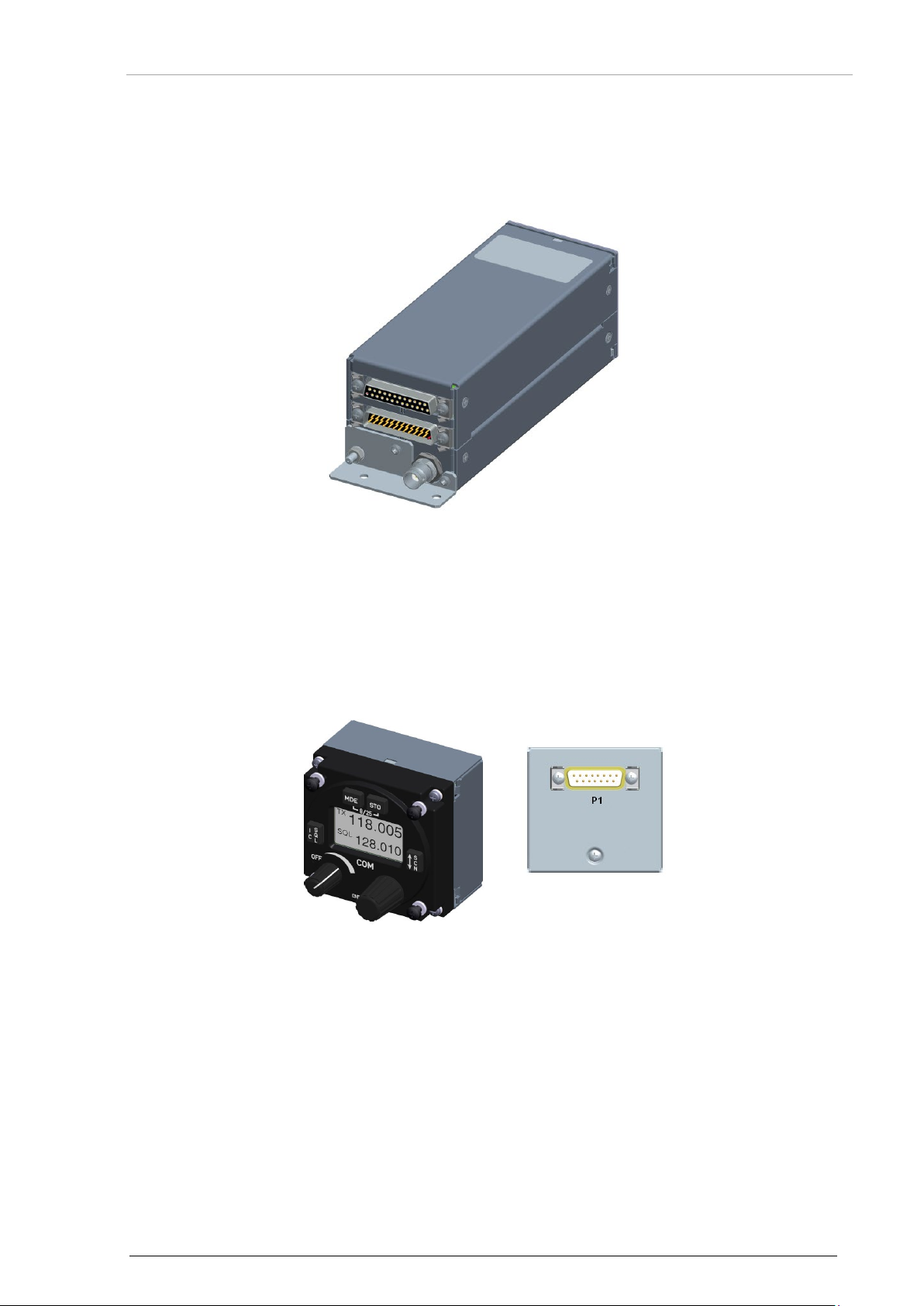
1.4.2.1 GT6201 Single Block Transceiver
• All controls and indicators are on the front panel.
The equipment connectors and the antenna socket are at the rear side of the device.
• Installation with four screws (rear panel installation).
The dimensions agree with the standard instrument diameter of 58 mm (2¼ inch).
Options*
R= Remote Controlled (optional)
14 GT6201 DV17001.03 Issue 06 January 2019
Figure 1: GT6201 Single Block Transceiver
Page 15
Becker Avionics
General Description
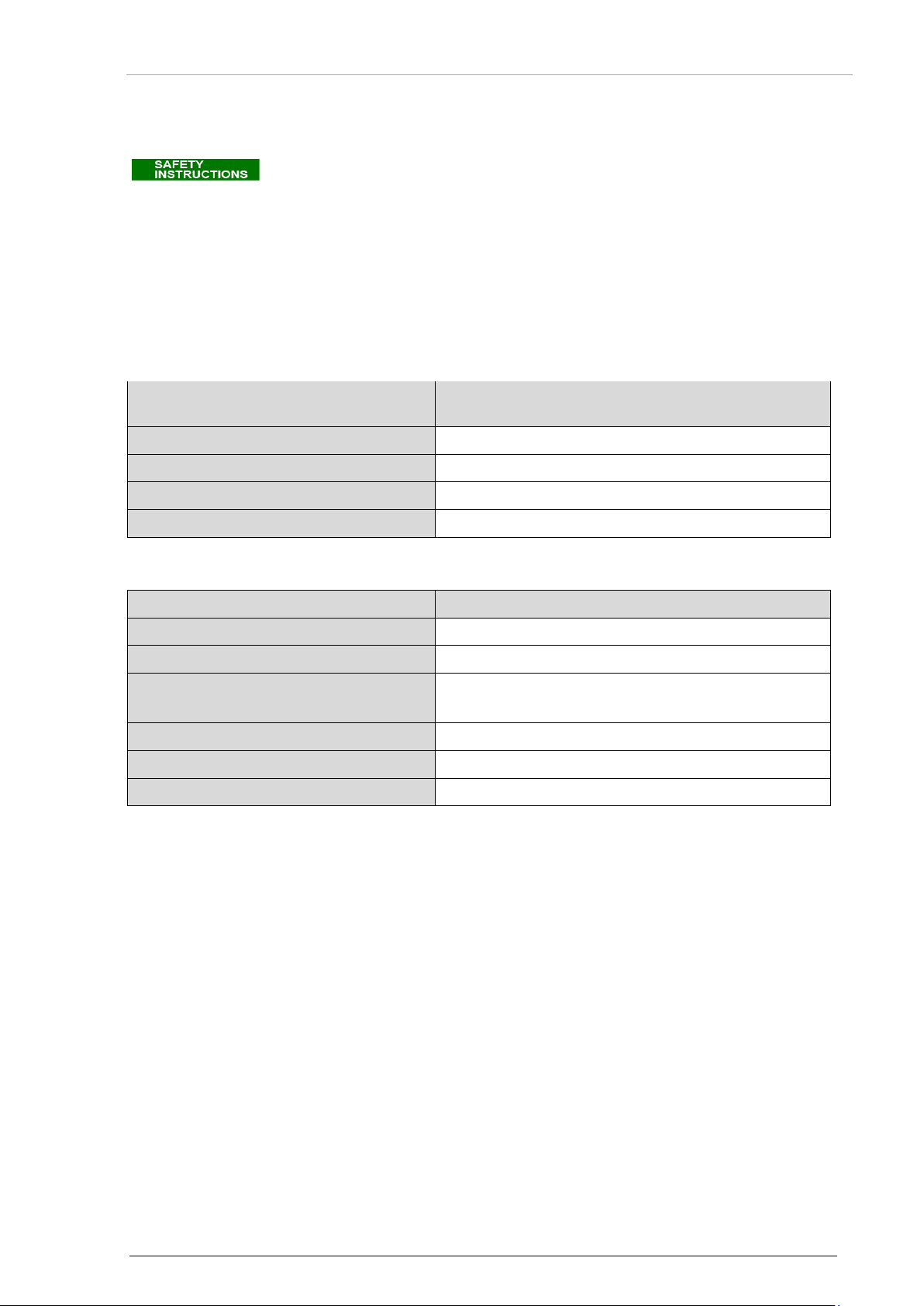
1.4.2.2 GT6201-XX-R Remote-Controlled Transceiver
• The GT6201-XX-R is a remote-controlled device. It does not include a control panel.
• It can receive commands and supplies data through the RCU62X1 (Remote Control Unit)
or a third-party controller.
Figure 2: GT6201 Remote-Controlled Transceiver
1.4.2.3 RCU62X1 Remote Control Unit
• All controls and indicators are on the front panel.
The equipment connectors are at the rear side of the device.
• Installation with four screws (rear panel installation).
The dimensions agree with the standard instrument diameter of 58 mm (2¼ inch).
Variants Overview
DV17001.03 Issue 06 January 2019 GT6201 15
Figure 3: RCU62X1 Remote Control Unit
Page 16

General Description
Becker Avionics
Scope of Functionality
mixed mode
1.5 Scope of Functionality
1.5.1 Frequency Indication
• A liquid crystal display (LCD) do the frequency indication.
• The required operating frequency is selectable with a rotary encoder.
• The relation between the real operating frequency and the shown frequency complies with
Operating frequency
the standards (ICAO Annex 10, Volume II).
Channel spacing
MHz
kHz
118.0000 25 118.000 118.00
118.0000 8.33 118.005 N/A
118.0083 8.33 118.010 N/A
118.0166 8.33 118.015 N/A
118.0250 25 118.025 118.02
etc. etc. etc. etc.
Frequency shown on the display
8.33 + 25 kHz
25 kHz mode
136.9750 25 136.975 136.97
136.9750 8.33 136.980 N/A
136.9833 8.33 136.985 N/A
136.9916 8.33 136.990 N/A
1.5.2 Audio Outputs
The GT6201 has four configurable outputs:
• Headphone 1 output:
o Rated output power is 300 mW into 75 Ω.
• Headphone 2 output:
o Rated output power is 200 mW into 75 Ω.
• Speaker output:
o Rated output power is 4 W into 4 Ω.
• LINE-OUT output:
o For ground station use only.
Note: Headphone 2 and the speaker output cannot be active at the same time.
1.5.3 Mike Inputs
• The GT6201 has four microphone inputs:
o Standard microphone input 1 (STD_MIKE1)
o Standard microphone input 2 (STD_MIKE2)
o Standard microphone input 3 (STD_MIKE3)
o Dynamic microphone input (DYN_MIKE)
• Each input can operate with one single microphone or with two microphones of the same
type connected in parallel.
16 GT6201 DV17001.03 Issue 06 January 2019
Page 17

Becker Avionics
General Description
1.5.4 AF Auxiliary Input
• The AF auxiliary input is the interface to connect an external audio source (e.g. other radio
services, music-player) .
o The interconnection of multiple external audio sources on this port make an
additional external decupling/isolation resistor necessary.
o The external audio is audible only when the transceiver is in receiving mode.
o The individual audio volume is set directly at the external equipment.
1.5.5 Sidetone
• The sidetone is available on the headphone output during transmission.
• The sidetone volume depends on to the intercom volume setting.
1.5.6 Squelch Operation
• The squelch (muting) circuit suppresses signals with strong signal noise (when enabled).
• There are two kinds of squelch methods implemented, carrier- and noise-squelch.
o The carrier-squelch depends on the signal strength and is adjustable in
configuration setup.
o The noise-squelch depends on the noise level and is adjustable in the user menu.
1.5.7 Memory Channels
• You can can store 99+9 frequencies.
o The user can give a defined text label to each stored frequency.
o The last recently used 9 (active) frequencies are stored automatically as "LAST"
channels.
1.5.8 Scan Mode
• The scan mode is a dual watch function.
o The device monitors frequencies on two different channels, active & preset
frequency at the same time.
o The signal of the active frequency is always audible it has priority at all times.
1.5.9 Illumination
• The illumination of LCD and keys is controlled from the front panel with the user menu or
externally with the dimming input lines.
• If external dimming is selected, the illumination curve (brightness to voltage relation) is
adjustable in configuration setup.
1.5.10 LOW BATT Indication
• The transceiver monitors the power supply voltage.
o If the power supply voltage is less than the adjusted threshold, the display shows
the message "LOW BATT".
o If the power supply voltage decreases further, an emergency operation mode
starts.
1.5.11 Emergency Operation
• If the power supply voltage is < 10.25 V, the device continues operation with decreased
performance.
• If power supply voltage is < 9.0 V, the device switches off automatically.
Scope of Functionality
DV17001.03 Issue 06 January 2019 GT6201 17
Page 18

General Description
Becker Avionics
Scope of Functionality
1.5.12 Built-In Tests
Power-On Built-In Test
• After power-on, the device starts a self-test (PBIT).
o The display shows the message "WAIT" and the software versions of the control
head and the chassis module.
o If there is an error the display shows the message "FAILURE, push any key".
o If there is no error the transceiver changes to the last active mode before power
off.
Continuous Built-In Test
• During normal operation, a self-test (CBIT) permanently examine the correct operation of
the device.
o The display shows an error message, if there is an error during CBIT.
1.5.13 Configuration Setup
The configuration setup is for the configuration of installation and device parameters such as mike
sensitivity, mike type selection, speaker enable/disable and other parameters.
1.5.14 Service Mode
• The service mode is a special configuration mode.
• You can get access to the service mode through the RS422 interface with a proprietary
serial data communication protocol.
• This mode is for use by authorized maintenance organizations only.
18 GT6201 DV17001.03 Issue 06 January 2019
Page 19

Becker Avionics
General Description
1.6 Safety-Conscious Utilization
o These cleaning agents can cause damages.
The product is to be used inside the declared limits.
For safe operation of the product the notes have to be obeyed:
• The installation may be carried out only by authorized personnel. The
country regulations always have to be obeyed.
• Use the device only within the specified conditions, see "Technical
Data", page 20.
• Power supply:
o Do not connect the device to AC sources.
o Make sure that the device is connected to the mandatory
DC source, see "Technical Data", page 20.
o Do not connect the device with reversed polarity to the DC source.
• Circuit breaker:
o Use the recommended fuses in the power supply line for the
protection of the application, see "Technical Data", page 20.
Cleaning:
• Do not use aggressive cleaning agents e.g. Acetone.
1.7 Restriction for Use
Restriction for Use
DV17001.03 Issue 06 January 2019 GT6201 19
Page 20

General Description
Becker Avionics
Technical Data
GT6201
Specifications
Nominal supply voltage range
11.0…30.3 VDC
Extended supply voltage range
10.25…32.2 VDC
Emergency operation
9.0...10.25 VDC
Dimming control voltage
0…14 VDC or 0…28 VDC
Internal fuse protection
7 A
Recommended external fuse protection
5 A
Frequency range
118.000...136.990 MHz
Channel spacing
8.33 / 25 kHz
Number of channels
25 kHz channel spacing
760 (118.000…136.975)
8.33 kHz channel spacing
2280 (118.000…136.990)
Modulation type
AM
25 kHz
6K80A3EJN
Temperature range
Operating: -20...+55 °C
Power consumption
Power off state @ 12 VDC
GT6201-05 (6 W): ≤ 0.10 mA
Power off state @ 24 VDC
GT6201-05 (6 W): ≤ 0.10 mA
Reception standby mode @ 12 VDC,
GT6201-05 (6 W): ≤ 140 mA
Reception standby mode @ 24 VDC,
GT6201-05 (6 W): ≤ 80 mA
Transmission mode @ 12 VDC,
GT6201-05 (6 W): 2.0 A @ 85%
1.8 Technical Data
1.8.1 General Characteristics
panel backlight off
panel backlight off
8.33 kHz
5K00A3EJN
Storage: -55...+85 °C
GT6201-10 (10 W): ≤ 0.10 mA
GT6201-05-R (6 W): ≤ 0.10 mA
GT6201-10-R (10 W): ≤ 0.10 mA
GT6201-10 (10 W): ≤ 0.10 mA
GT6201-05-R (6 W): ≤ 0.10 mA
GT6201-10-R (10 W): ≤ 0.10 mA
GT6201-10 (10 W): ≤ 140 mA
GT6201-05-R (6 W): ≤ 120 mA
GT6201-10-R (10 W): ≤ 120 mA
GT6201-10 (10 W): ≤ 80 mA
GT6201-05-R (6 W): ≤ 80 mA
GT6201-10-R (10 W): ≤ 80 mA
VSWR=1:1
20 GT6201 DV17001.03 Issue 06 January 2019
GT6201-10 (10 W): -GT6201-05-R (6 W): 2.0 A @ 85%
GT6201-10-R (10 W): --
Page 21

Becker Avionics
General Description
Technical Data
Transmission mode @ 24 VDC,
GT6201-05 (6 W): --
GT6201 Receiver Data
Specifications
Sensitivity
-101 dBm for a SINAD of 12 dB (nominal)
Adjacent channel rejection
≥ 60 dB
Spurious response rejection
≥ 70 dB
Intermodulation response rejection
≥ 70 dB
Blocking or desensitization
> 99 dB
Cross modulation rejection
≥ 95 dB
Harmonic distortion (THD)
m = 30% ≤ 5%
Effective bandwidth: 25 kHz channel spacing
±8.5 kHz
8.33 kHz channel spacing
±2.8 kHz
AGC characteristic
≤ 6 dB in range -101...-1 dBm
Audio frequency response
25 kHz channel spacing
-4 dB / +2 dB 300...3400 Hz relative to 1000 Hz
8.33 kHz channel spacing
-4 dB /+2 dB 350...2500 Hz relative to 1000 Hz
Squelch
6 dB (S+N)/N up to 12 dB, adjustable
Audio noise
40 dB (S+N)/N
Audio distortion
at 30%, 50% rated output power
≤ 5%
at 90%, 50% rated output power
≤ 10%
VSWR=1:1
GT6201-10 (10 W): 1.5 A @ 85%
GT6201-05-R (6 W): -GT6201-10-R (10 W): 1.5 A @ 85%
Note: GT6201 10 W variants @ 24 VDC and more, decreased TX power to < 24 V
1.8.2 Receiver Data
-107 dBm for a SINAD of 6 dB
(-101 dBm equals 1.993 µV; -107 dBm equals 1 µV)
m = 90% ≤ 10%
DV17001.03 Issue 06 January 2019 GT6201 21
Page 22

General Description
Becker Avionics
Technical Data
GT6201 Receiver Data
Specifications
Rated output power for speaker
≥ 4 W into 4 Ω
Rated output power for headphone 1
≥ 300 mW into 75 Ω
Rated output power for headphone 2
≥ 200 mW into 75 Ω
Audio auxiliary input
50 mV...8 V (adjustable) across 600 Ω
Offset-carrier operation
N/A
GT6201 Transmitter Data
Specifications
Output power into 50 Ω
GT6201-05: ≥ 6 W
GT6201-10: ≥ 10 W
Frequency tolerance
≤ ±1 ppm
Duty cycle
120 s (TX) : 480 s (RX)
Modulation depth
≥ 85%
Modulation distortion
≤ 10%
Audio frequency response
25 kHz channel spacing
-4 dB / +2 dB in band 300...3400 Hz relative to 1000 Hz
8.33 kHz channel spacing
-4 dB / +2 dB in band 350...2500 Hz relative to 1000 Hz
Dynamic microphone
0.5…25 mV compressor starting point, adjustable
(with compressor)
Input balanced, 200 Ω
Standard microphone(s)
9…1500 mV compressor starting point, adjustable
(with compressor)
Input unbalanced, 150 Ω
FM deviation with modulation
≤ 3 kHz (≤ 800 Hz typ.)
Sidetone
adjustable
Automatic shutdown of transmit mode
120 s
1.8.3 Transmitter Data
≥ 100 mW into 600 Ω
≥ 100 mW into 600 Ω
(with and without modulation)
GT6201-05-R: ≥ 6 W
GT6201-10-R: ≥ 10 W
≤ -25 dB above 5000 Hz
≤ -25 dB above 3200 Hz
Input range up to 20 dB above compressor starting
point.
22 GT6201 DV17001.03 Issue 06 January 2019
Input range up to 20 dB above compressor starting
point.
(factory configurable 30…120 s)
Page 23
Becker Avionics
General Description
1.8.4 Emergency Operation
• If the supply voltage is < 9.0 Volt, the device is automatically set to "OFF".
(Emergency Operation)
Panel & Display Backlight
switched off (for saving BATT energy)
TX Output Power
≥ 2 W into 50 Ω (with modulation)
TX Modulation Depth
≥ 50%
RX Sensitivity
≤ -93 dBm for a (S+N)/N ratio of 6 dB
GT6201
Specifications
Device (W x H x D)
61 x 61 x 205.7 mm (2.4 x 2.4 x 8.98 inch)
Installation depth
184.8 mm (7.28 inch)
Installation
Rear-panel standard
Material
AlMg/Plastic
Surface treatment
Control-head coated with black matt paint
Weight
645 g (1.42 lbs)
Emergency Operation: 9.0…10.25 VDC (decreased performance).
• The display shows "LOW BATT" if the supply voltage is less than the
predefined threshold.
o That is the note for the user, that he should connect a headset
because the speaker could be switched "OFF" soon.
• If the supply voltage is < 10.25 V, the device continues operation with
decreased performance.
o The speaker output of the transceiver is automatically set to "OFF"
without further indication.
o A headset is required to continue operation of the transceiver.
GT6201, RCU62X1
1.8.5 Dimensions & Weight
Specifications
Technical Data
Ø58 mm (2¼ inch)
DV17001.03 Issue 06 January 2019 GT6201 23
Page 24

General Description
Becker Avionics
Unauthorized changes or modifications to the device(s) may void the compliance
EASA.21O.1249 ETSO-2C37e ETSO-2C38e
RCU6211-(012)
0662.453-910
pending
Technical Data
1.8.6 Software
The design and development processes used for AR6201 family software are in compliance with the
rules given in EUROCAE/RTCA Document ED-12B/DO-178B; “Software Considerations in Airborne
System and Equipment Certification”. Hereby ‘Design Assurance Level’ (DAL) "C" was followed and
the complete software documentation is based on this level.
1.8.7 Hardware
The devices do not contain Complex Electronic Hardware (CEH).
1.8.8 Certifications
to the required regulatory agencies and authorization for continued equipment
GT6201 meets the requirements of ETSI EN 300 676 regulations
Part Number Article Number Approval
usage.
GT6201-05 0637.351-923
BAF - German Federal Supervisory Office for
Air Navigation Services
D-0030/2014
GT6201-10 0637.361-923
Ministero Sviluppo Economico –
Dipartimento per le Comunicazioni
GT6201-05-R 0641.073-923
Registro ufficiale, Prot.n. 0041697-02/07/2014
Austria Notification:
BMVIT-640.825/0301-Ⅲ/BFT/2016
GT6201-10-R 0641.081-923
RCU62X1 meets the requirements of:
Part Number Article Number Approval
RCU6201-(012) 0631.469-910
TSO-C169a
24 GT6201 DV17001.03 Issue 06 January 2019
Page 25

Becker Avionics
General Description
1.9 Order Code
Qty
VHF-Transceiver
1
GT6201-05, VHF Ground Transceiver,
1
GT6201-10, VHF Ground Transceiver,
1
GT6201-05-R, VHF Ground Transceiver, remote-controlled,
1
GT6201-10-R, VHF Ground Transceiver, remote-controlled,
Qty
Control Unit
1
RCU6201-(012), 8.33/25 kHz
1
RCU6211-(012), 8.33/25 kHz
Article-No. 0662.453-910
Qty
Installation
1
Vehicle Kit VK4201
• 1KA003, Antenna cable, length 2.5 m
Qty
Available Documentation
1
(I&O) GT6201 Installation and Operation manual, English
1
(M&R) GT6201 Maintenance and Repair manual, English
1
Quick Start Guide English/German
1
Quick Start Guide English/French
1.9.1 GT6201
≥ 6 Watt RF Power Output
≥ 10 Watt RF Power Output
≥ 6 Watt RF Power Output
≥ 10 Watt RF Power Output
1.9.2 RCU62X1
1.9.3 Accessories
Order Code
Article-No. 0637.351-923
Article-No. 0637.361-923
Article-No. 0641.073-923
Article-No. 0641.081-923
Article-No. 0631.469-910
• 1PM012, Dynamic microphone
• 1PL011, Speaker with housing and cables
• 1E024, Car installation
• 1K044, Cable harness
• 1A002-1, Antenna
1.9.4 Documentation
Article-No. 0892.424-923
Article-No. 0640.093-071
Article-No. 0640.107-071
Article-No. 0646.911-071
Article-No. 0648.906-071
DV17001.03 Issue 06 January 2019 GT6201 25
Page 26

General Description
Becker Avionics
Order Code
Blank Page
26 GT6201 DV17001.03 Issue 06 January 2019
Page 27

Becker Avionics
Installation
Limitations
2 Installation
This manual must be available close to the device during the performance of all tasks.
The installation of the transceiver depends on the location and its equipment. Therefore, this section
only s general information.
Careful planning should be applied to achieve the desired performance and reliability from the product.
Any deviations from the installation instructions in this document are under own responsibility.
In this chapter you can read about:
2.1 Limitations ................................................................................................................................... 28
2.2 Packaging, Transport, Storage ................................................................................................... 28
2.3 Device Assignment ..................................................................................................................... 29
2.3.1 Scope of Delivery .............................................................................................................. 29
2.3.2 State of Delivery ................................................................................................................ 29
2.3.3 Additional Required Equipment ........................................................................................ 29
2.3.4 Type Plate ......................................................................................................................... 30
2.3.5 Software/Firmware Status – Functionality ........................................................................ 30
2.4 Installation Requirements ............................................................................................................ 31
2.4.1 Installation in a Vehicle ..................................................................................................... 31
2.4.2 Rear Panel Installation ...................................................................................................... 31
2.5 Dimensions.................................................................................................................................. 32
2.5.1 GT6201 ............................................................................................................................. 32
2.5.2 GT6201-XX-R ................................................................................................................... 33
2.5.3 RCU62X1 .......................................................................................................................... 34
2.5.4 GT6201, RCU62X1 Rear Panel Installation ..................................................................... 34
2.6 Connector Pin Assignments ........................................................................................................ 35
2.6.1 Antenna Connector (GT6201) .......................................................................................... 35
2.6.2 Grounding Bolt (GT6201) ................................................................................................. 35
2.6.3 Connector P1 (GT6201).................................................................................................... 35
2.6.4 Connector J1 (GT6201) .................................................................................................... 36
2.6.5 Inputs / Outputs (GT6201) ................................................................................................ 37
2.6.6 Connector Layout RCU62X1 ............................................................................................ 40
2.6.7 Connector P1 (RCU62X1) ................................................................................................ 40
2.6.8 Inputs / Outputs (RCU62X1) ............................................................................................. 41
2.7 Wiring .......................................................................................................................................... 42
2.7.1 Car Cable Harness 1K044 ................................................................................................ 42
2.8 Installation and Configuration ..................................................................................................... 43
2.8.1 Antenna Installation .......................................................................................................... 43
2.9 Configuration Setup .................................................................................................................... 44
2.9.1 Start Configuration Setup ................................................................................................. 44
2.9.2 Configuration Setup Pages ............................................................................................... 45
2.10 Factory Default Settings .............................................................................................................. 56
2.11 Post Installation Check ................................................................................................................ 59
2.11.1 Mechanical Installation and Wiring Check ........................................................................ 59
2.11.2 Power Supply .................................................................................................................... 59
2.11.3 Receiver / Transmitter Operation ...................................................................................... 59
2.11.4 Antenna Check ................................................................................................................. 59
2.12 Error / Failure Indication .............................................................................................................. 59
2.13 Troubleshooting .......................................................................................................................... 60
DV17001.03 Issue 06 January 2019 GT6201 27
Page 28

Installation
Becker Avionics
Unauthorized changes or modifications to the device(s) may void the compliance
The packaging material is inflammable, if it is disposed of improperly by burning,
Limitations
2.1 Limitations
• The GT6201 is made for ground-based transceiver installation for the management of air
and ground traffic operations.
• The equipment is not qualified for installation in areas where fluid contamination is quite
likely.
to the required regulatory agencies and authorization for continued equipment
usage.
2.2 Packaging, Transport, Storage
Visually inspect the package contents for signs of transport damage.
toxic fumes may develop.
Keep the packaging material and use it in the case of a return shipment. Improper or faulty packaging
may lead to transport damages.
Make sure to transport the device always in a safe manner and with the aid of suitable lifting
equipment if necessary. Do never use the electric connections for lifting. Before the transport, a clean,
level surface should be prepared to put the device on. The electric connections may not be damaged
when placing the device.
First Device Checkup
• Check the device for signs of transport damages.
• Please make sure that the indications on the type plate agree with your purchase order.
• Make sure that the equipment is complete ("Scope of Delivery", page 29).
Storage
If you do not wish to mount and install the device immediately, make sure to store it in a dry and clean
environment. Make sure that the device is not stored near strong heat sources and that no metal
chippings can get into the device.
28 GT6201 DV17001.03 Issue 06 January 2019
Page 29

Becker Avionics
Installation
2.3 Device Assignment
This manual is valid for the devices:
• GT6201-05.
• GT6201-10.
• GT6201-05-R with RCU6201-(012) or RCU6211-(012).
2.3.1 Scope of Delivery
2.3.2 State of Delivery
2.3.3 Additional Required Equipment
Details see "Accessories", page 25.
• GT6201-10-R with RCU6201-(012) or RCU6211-(012).
from Software Version
SCI1050S305 Version 3.08 (and higher).
SCI1051S305 Version 1.56 (and higher).
• Manuals:
o Installation and Operation.
• Device in accordance with your order.
• The device(s) are ready for use with factory default adjustments.
• Antenna (VHF COM, with coaxial 50 Ω impedance cable and BNC connector).
• Installation material.
• Connector kits.
• Cable harness.
• Microphone.
• Headphone or speaker.
Device Assignment
DV17001.03 Issue 06 January 2019 GT6201 29
Page 30

Installation
Becker Avionics
(P/N):
GT6201 = Single Block VHF-Ground-Transceiver 58 mm (2¼ inch)
Example type designation: RCU6201:
RCU6201 = Remote Control Uni 58 mm (2¼ inch)
SN
(S/N):
Unique number of the particular device
(A/N):
Article number
DoM:
Date of Manufacturing
Device Assignment
2.3.4 Type Plate
The device type is specified by the type plate (on the housing):
Example:
Figure 4: Type Plate (Example)
Explanation:
PN
AN
Example type designation: GT6201-10:
Options:
-05 6 Watt transceiver
-10 10 Watt transceiver
-XX-R Remote-controlled transceiver
Options:
0XX 8.33/25 kHz channel spacing capability
X1X 6 W @ 14 V / 10 W @ 28 V
XX2 white illumination color on black panel
Software
Refer to the version on the device type plate
Compliance and Certifications
Refer to the text and logos on the device type plate
2.3.5 Software/Firmware Status – Functionality
• The software version is shown at the screen for a few seconds after power on.
This information is also available with the configuration setup → DEVICE INFO.
• The software versions are subject to change without notice.
30 GT6201 DV17001.03 Issue 06 January 2019
Page 31

Becker Avionics
Installation
Installation Requirements
protection of the application, see "Technical Data", page 20.
2.4 Installation Requirements
The installation of the device(s) depends on the type of equipment and therefore only general
information is given in this section.
2.4.1 Installation in a Vehicle
• Find a suitable area to install the device.
• Use the vehicle kit VK4201 for installation (see "Accessories" page 25).
• Make sure that the user has easy access to the controls and indicators.
• More information please see "Dimensions", page 32.
2.4.2 Rear Panel Installation
• The GT6201 single block and the RCU62X1 are for rear panel installation.
o The four screws for installation are already attached at the front of the device.
o Circular cut out and the installation holes please see "GT6201, RCU62X1 Rear
Panel Installation", page 34.
• The device must not be opened.
• When installing the device, make sure the heat dissipators of the
device receive sufficient air.
• Keep an efficient distance of the devices with integrated ventilator
fans in order to ensure free circulation of the cooling air.
• Make sure that the mounting plate is not exposed to external
temperature influences.
• Keep a distance between GT6201 and other equipment of
min. 5 mm for air circulation.
• Forced cooling is usually not required.
Wiring:
The notes have to be obeyed:
• All electrical systems in the vehicle shall be switched off and
screened.
• No other leads should be included in the supply lead loop.
• Label all cable terminations to the equipment.
• The cable harness must be able to move freely and thus prevent
fracture of the wires.
• The cable harness must be in a position that the individual cables
are not abraded on the cabinet or chassis.
• Use twisted, shielded cables for connections to reduce interference
from electrical and magnetic fields.
• Use the recommended fuses in the power supply line for the
DV17001.03 Issue 06 January 2019 GT6201 31
Page 32

Installation
Becker Avionics
Dimensions
CENTER OF GRAVITY
61 (2.4 in)
28.5±3 (1.12 in)
16.4 ±0.5
(0.65 in ±0.02)
205.7 ±1.5 (8.098 in ±0.059)
CG
168.4 ±0.8 (6.63 in ±0.031)
72.6 ±5
(2.86 in ±0.2)
CG
17.9 ±0.4
(0.70 in ±0.016)
3 ±0.1
(0.12 in ±0.004)
34.4±3 (1.35 in ±0.12)
Permitted deviation for dimensions without tolerances: DIN ISO 2768 T1 C (dimensions in mm)
xx...6 (±0.3)
>30...120 (±0.8)
>400...1000 (±2.0)
>6...30 (±0.5)
>120...400 (±1.2)
>1000...2000 (±3.0)
2.5 Dimensions
2.5.1 GT6201
Dimensions mm (inch)
Figure 5: Dimensions: GT6201 Single Block Transceiver
32 GT6201 DV17001.03 Issue 06 January 2019
Page 33

Becker Avionics
Installation
CENTER OF GR AVITY
188±1 (7.4 in ±0.4)
172.5±1 (6.79 in ±0.4)
164.9±0.5 (6.49 in ±0.196)
84±0.3 (3.31 in ±0.012)
15
(0.59 in)
40
(1.57 in)
30.5
(1.20 in)
61 (2.4 in)
25 (0.98 in)
30
(1.18 in)
Permitted deviation for dimensions without tolerances: DIN ISO 2768 T1 C (dimensions in mm)
xx...6 (±0.3)
>30...120 (±0.8)
>400...1000 (±2.0)
>6...30 (±0.5)
>120...400 (±1.2)
>1000...2000 (±3.0)
2.5.2 GT6201-XX-R
Dimensions
Dimensions mm (inch)
Figure 6: Dimensions: GT6201-XX-R Remote-Controlled Transceiver
DV17001.03 Issue 06 January 2019 GT6201 33
Page 34

Installation
Becker Avionics
Dimensions
39.3
(1.55 in)
61 (2.4 in)
65.9±0.4 (2.59 in ±0.015)
60.2±0.4 (2.37 in ±0.015)
Permitted deviation for dimensions without tolerances: DIN ISO 2768 T1 C (dimensions in mm)
xx...6 (±0.3)
>30...120 (±0.8)
>400...1000 (±2.0)
>6...30 (±0.5)
>120...400 (±1.2)
>1000...2000 (±3.0)
Figure 8: GT6201, RCU62X1 Front View
Figure 9: Drilling Template (Rear-Panel Installation)
2.5.3 RCU62X1
Dimensions mm (inch)
Figure 7: Dimensions RCU62X1 (Side View)
2.5.4 GT6201, RCU62X1 Rear Panel Installation
61x61 mm (2.4x2.4 in)
Dimensions mm (inch)
(no scale drawing)
34 GT6201 DV17001.03 Issue 06 January 2019
Page 35

Becker Avionics
Installation
2.6 Connector Pin Assignments
1: Antenna connector
P1 (GT6201)
Pin No.
P1-1
SPK_HI
OUT
Speaker output signal (high)
P1-2
HDPH1_A
OUT
Balanced output for headphone(s)1
P1-3
HDPH1_B
OUT
Balanced output for headphone(s)1
P1-4
AF_AUX_IN_HI
IN
Auxiliary audio input (high)
P1-5
MIKE_DYN_HI
IN
Balanced input for dynamic microphone(s)
P1-6
MIKE_DYN_LO
IN
Balanced input for dynamic microphone(s)
P1-7
/IC
IN
Intercom key input;
P1-8
MIKE_STD_LO
-
Standard microphone(s) low (ground) used for STD1,
P1-9
MIKE_STD2_HI
IN
Standard microphone 2 High (high)
P1-10
ILL_LO
IN
Illumination low input
P1-11
P_SUPP
IN
Power supply high (positive)
P1-12
P_SUPP
IN
Power supply high (positive)
P1-13
P_SUPP_GND
-
Power supply ground
P1-14
SPK_LO
-
Speaker ground
P1-15
LINE_OUT
OUT
Linear audio output, unbalanced
P1-16
AGC_OUT
OUT
Receiver AGC output
2.6.1 Antenna Connector (GT6201)
• The antenna connector is a BNC type.
• The antenna port is made for operating with a nominal impedance of 50 Ω.
2.6.2 Grounding Bolt (GT6201)
• The transceiver has a M4 threaded grounding bolt to do a low impedance grounding of the
device.
o It is to avoid damage or malfunction in the case of indirect lightning, EMI and HIRF
conditions.
Connector Pin Assignments
2: Grounding bolt
3: P1
4: J1
2.6.3 Connector P1 (GT6201)
D-SUB male connector with 25 pins and slide-in fastener.
Figure 10: GT6201 – Connector Layout
Pin Name Direction Function
ACTIVE state - closed contact to GND
STD2 and STD3
DV17001.03 Issue 06 January 2019 GT6201 35
Page 36

Installation
Becker Avionics
P1 (GT6201)
Pin No.
P1-17
/PTT1
IN
Push To Talk key input1
P1-18
MIKE_STD1_HI
IN
Standard Microphone 1 High (high)
P1-19
MIKE_STD3_HI
IN
Standard Microphone 3 High (high)
P1-20
HDPH2_A
OUT
Balanced Output for headphone(s)2
P1-21
AF_AUX_IN_LO
IN
Auxiliary audio input low
P1-22
HDPH2_B
OUT
Balanced output for headphone(s)2
P1-23
ILL_HI
IN
Illumination high
P1-24
/PWR_EVAL
OUT
Power on monitor output
P1-25
P_SUPP_GND
-
Power supply ground
J1 (GT6201)
Pin No.
J1-1
CPIN
-
Reserved coding pin
J1-2
TX2+
OUT
Auxiliary control interface
J1-3
RX2+
IN
Auxiliary Control Interface
J1-4
/SQL_EVAL
OUT
Squelch monitor output
J1-5
/PTT2
IN
Push-To-Talk key input 2
J1-6
SHIELD_1
-
Secondary control & service interface SHIELD
J1-7
TX1+
OUT
Secondary control & service interface
J1-8
RX1+
IN
Secondary control & service interface
J1-9
TX2-
OUT
Auxiliary control interface
J1-10
RX2-
IN
Auxiliary control interface
J1-11
SHIELD_2
-
Auxiliary control interface SHIELD
J1-12
/EXT_SO
IN
External "Exchange" key
J1-13
/SRV_EN
IN
Service enable pin
J1-14
TX1-
OUT
Secondary control & service interface
J1-15
RX1-
IN
Secondary control & service interface
J1-16
NC not connected
J1-17
/SQL_SW
IN
"Squelch Force-OFF" input
J1-18
NC not connected
J1-19
NC not connected
J1-20
/ISOL
IN
"ISOL" input
Connector Pin Assignments
Pin Name Direction Function
ACTIVE state - closed contact to GND
2.6.4 Connector J1 (GT6201)
D-SUB female connector with 25 sockets and slide-in fastener.
Pin Name Direction Function
ACTIVE state - closed contact to GND
ACTIVE state - closed contact to GND
Falling edge will activate frequency exchange
36 GT6201 DV17001.03 Issue 06 January 2019
ACTIVE state - closed contact to GND
ACTIVE state - closed contact to GND
ACTIVE state - closed contact to GND
Page 37

Becker Avionics
Installation
J1 (GT6201)
Pin No.
Pin Name Direction Function
J1-21
D_GND
-
Discrete lines ground
J1-22
D_GND
-
Discrete lines ground
J1-23
D_GND
-
Discrete lines ground
J1-24
/MIKE_SW
IN
Configuration selector CFG1 and CFG2
J1-25
/EXT_ON
IN
External Power ON input
Pin No.
Pin Name
Direction
Function
P1-8
MIKE_STD_LO
-
Standard microphone(s) low (ground) used for
P1-9
MIKE_STD2_HI
IN
Standard microphone 2 high (high)
P1-18
MIKE_STD1_HI
IN
Standard microphone 1 high (high)
P1-19
MIKE_STD3_HI
IN
Standard microphone 3 high (high)
Pin No.
Pin Name
Direction
Function
P1-5
MIKE_DYN_HI
IN
Balanced input for dynamic microphone(s)
P1-6
MIKE_DYN_LO
IN
Balanced input for dynamic microphone(s)
Connector Pin Assignments
ACTIVE state - closed contact to GND
2.6.5 Inputs / Outputs (GT6201)
Microphone Connection – Standard Microphones
STD1, STD2 and STD3
• The transceiver has three unbalanced inputs STD1, STD2 and STD3.
• Each input has an input impedance of 150 Ω and a nominal sensitivity of 110 mV.
• The sensitivity level is adjustable in the configuration setup independently for each of the
microphones.
• The power supply from pins P1-9, P1-18 and P1-19 for supply of the connected
microphone(s) is > 8 VDC (8.3 V nominal) open circuit with an output impedance of 120 Ω.
Note:
• For common aviation microphones the power supply is able to support two microphones in
parallel.
• It is recommended to combine only microphones of the same type / impedance.
• In installations where high interferences were detected, we recommend the use of
sensitivity levels between 27...1500 mV.
• We also recommend to install the jacks generally isolated from car frame in order to avoid
ground loops.
Microphone Connection - Dynamic Microphone
• Interfacing with dynamic microphones, the transceiver has balanced inputs with an
impedance of 140 Ω and a nominal sensitivity of 1.6 mV.
• This sensitivity level is adjustable in the configuration setup.
• Two dynamic microphones in parallel may be connected (identical technical
characteristics of the microphones are recommended).
Note:
• In installations where high interferences are detected we recommend the use of sensitivity
levels between 2...20 mV.
• We also recommend to install the jacks generally isolated from car frame in order to avoid
ground loops.
DV17001.03 Issue 06 January 2019 GT6201 37
• Use microphone cables with shielded wires.
Page 38

Installation
Becker Avionics
Pin No.
Pin Name
Direction
Function
P1-1
SPK_HI
OUT
Speaker output signal
P1-14
SPK_LO
-
Speaker ground
Pin No.
Pin Name
Direction
Function
P1-2
HDPH1_A
OUT
Balanced output for headphone(s) 1
P1-3
HDPH1_B
OUT
Balanced output for headphone(s) 1
P1-20
HDPH2_A
OUT
Balanced output for headphone(s) 2
P1-22
HDPH2_B
OUT
Balanced output for headphone(s) 2
Pin No.
Pin Name
Direction
Function
P1-10
ILL_LO
IN
Illumination low input
P1-23
ILL_HI
IN
Illumination high input
Pin No.
Pin Name
Direction
Function
P1-4
AF_AUX_IN_HI
IN
Auxiliary audio input high
P1-21
AF_AUX_IN_LO
-
Auxiliary audio input low ground
Pin No.
Pin Name
Direction
Function
P1-14
SPK_LO
-
Speaker ground
P1-15
LINE_OUT_HI
OUT
Linear audio output, unbalanced
Connector Pin Assignments
Speaker Connection
• The speaker output supplies nominal 4 W into 4 Ω.
Headphone(s) Connection
• The headphone 1 output is a balanced, transformer-coupled output providing nominal
300 mW into 75 Ω.
o Use a shielded single wire for headphones requires an unbalanced output
configuration. To get this, ground P1-3 (connect pin P1-13 with P1-25).
• The headphone 2 output is a balanced output providing nominal 200 mW into 75 Ω.
• You can connect up to two headphones with phone-impedance of 300 Ω (or higher) in
parallel on each circuit, therefore you can connect up to four headphones at the same
time.
CAUTION: The headphone 2 output shall be always floating (cannot be connected in
unbalance configuration as headphone 1).
Panel Illumination
• The VHF transceiver supplies illumination for the keys and the display.
• It depends on configuration if this illumination is controlled by front panel or externally.
• Connect ILL_LO (pin P1-10) to car ground.
• Connect ILL_HI (pin P1-23) to dimming bus.
"Auxiliary" Audio Input
• The AF auxiliary input is used to connect an external audio source (NAV, music-player,
etc.) to the transceiver.
• The external audio is audible only when transceiver is in receive mode.
• The input sensitivity is adjustable in the configuration setup.
• The impedance of this input is 600 Ω.
"LINE_OUT" Audio Output
• The LINE OUT is used to connect e.g. an external voice recorder to the transceiver when
it is used in ground-based installations.
• The LINE OUT output supplies nominal 1 V
into 1000 Ω.
RMS
38 GT6201 DV17001.03 Issue 06 January 2019
Page 39

Becker Avionics
Installation
External Power ON
Pin No.
Pin Name
Direction
Function
External Power ON input
Pin No.
Pin Name
Direction
Function
Push-To-Talk key input 1
Push-To-Talk key input 2
Pin No.
Pin Name
Direction
Function
Power on Monitor output:
Rel1
+Supply
/PWR_EVAL
Pin No.
Pin Name
Direction
Function
Indicates presence of the VHF channel’s signal
Connector Pin Assignments
J1-25 /EXT_ON IN
ACTIVE state - closed contact to GND
• The External Power ON input it is possibility to power "ON" the system when this pin is
connected to ground.
Push-To-Talk (/PTT)
P1-17 /PTT1 IN
J1-5 /PTT2 IN
• There are two Push-To-Talk inputs available /PTT1 and /PTT2.
• Each input has an internal pull up.
• While the input is connected to ground a current of < 1 mA flows.
o The transceiver enters transmit operation, if one or both inputs are connected to
ground.
• According to microphone(s) configuration, the signal from particular inputs can or cannot
modulate transmissions.
ACTIVE state - closed contact to GND
ACTIVE state - closed contact to GND
Power Indication (/PWR_EVAL)
P1-24 /PWR_EVAL OUT
• The output internally connects to ground when the device is "ON".
• A current of maximum 100 mA can flow to drive e.g. an external relay.
• The output has high impedance if the device is switched off.
Note: Connect a protection diode in parallel to the external relay to avoid damage of
this output..
GT6201 "OFF" - open circuit GT6201 on - closed
circuit to GND (max. 100 mA)
VHF Channel Signal Indication (/SQL_EVAL)
J1-4 /SQL_EVAL OUT
• This output indicates presence of the VHF channel’s signal on the audio outputs.
• It is an open collector output type.
• The output internally connects to ground when the device receives signal on the selected
VHF channel and this audio signal is available on audio outputs.
DV17001.03 Issue 06 January 2019 GT6201 39
• A current of maximum 100 mA can flow to drive e.g. an external relay.
• The output has high impedance if the device is switched off.
on the audio outputs.
Page 40

Installation
Becker Avionics
Connector Pin Assignments
Pin No.
Pin Name
Direction
Function
Configuration selector CFG1 and CFG2.
Pin No.
Pin Name
I/O
Function
P1-1
TX0_422+
OUT
Primary Control & Service Interface
P1-2
TX0_422-
OUT
Primary Control & Service Interface
P1-3
RX1_422+
IN
Auxiliary Control Interface
P1-4
RX0_422+
IN
Primary Control & Service Interface
P1-5
RX0_422-
IN
Primary Control & Service Interface
P1-6
ILL_LO
IN
Illumination low input
P1-7
TX1_422-
OUT
Auxiliary Control Interface
P1-8
ILL_HI
IN
Illumination high
Power supply Ground, shielding for RS422,
P1-10
RX1_422-
IN
Auxiliary Control Interface
P1-11
SUPP_IN
-
Power supply (positive)
Service enable pin
External Power ON input
P1-14
TX1_422+
OUT
Auxiliary Control Interface
External "Exchange" key
External Mike Switch (/MIKE_SW)
J1-24 /MIKE_SW IN
• The external mike switch is used for selection between the audio in/out configurations
CFG1 and CFG2.
• When /MIKE_SW is active then configuration CFG2 is in use.
• When /MIKE_SW is inactive then CFG1 is in use.
• The configurations CFG1 and CFG2 contain parameters which are set in the configuration
setup pages (for details, refer to chapter "Configuration Setup", page 44).
• You can change the configurations during the flight in the configuration setup.
2.6.6 Connector Layout RCU62X1
• Type: 15pin D-Sub male connector with slide-in fastener
ACTIVE state - closed contact to GND
2.6.7 Connector P1 (RCU62X1)
Figure 11: RCU62X1 - Connector Layout
P1-9 GND -
P1-12 /SRV_EN OUT
Ground for discrete lines
ACTIVE state - closed contact to GND
P1-13 /EXT_ON IN
P1-15 /EXCH_CH IN
40 GT6201 DV17001.03 Issue 06 January 2019
ACTIVE state - closed contact to GND
ACTIVE state - closed contact to GND
Page 41

Becker Avionics
Installation
Pin No.
Pin Name
I/O
Function
P1-6
ILL_LO
IN
Illumination low input
P1-8
ILL_HI
IN
Illumination high input
Pin No.
Pin Name
I/O
Function
External Power ON input/output
Pin No.
Pin Name
I/O
Function
External "Exchange" key
2.6.8 Inputs / Outputs (RCU62X1)
Panel Illumination
• These inputs are used to illuminate the RCU62X1 controller keys and the display.
• You can configure the illumination in the configuration setup with the front panel or
externally with P1-6/P1-8.
• For external configuration connect P1-6 to system ground and P1-8 to dimming voltage
bus.
External Power ON (/EXT_ON)
Connector Pin Assignments
P1-13 /EXT_ON IN/OUT
• This input/output is used to power on the system, for this connect P1-13 to ground.
• You can use this in installations with a central avionics power switch or to power on
GT6201.
External Exchange (/EXCH_CH)
P1-15 /EXCH_CH IN
• This input is used to change active and preset frequency or activate SCAN mode with a
switch.
ACTIVE state - closed contact to GND
ACTIVE state - closed contact to GND
DV17001.03 Issue 06 January 2019 GT6201 41
Page 42

Installation
Becker Avionics
Wiring
View soldering side
Connector shell
AWG24
AWG24
rear view
AWG22
AWG22
AWG22
AWG22
AWG22
2x red
AWG22
3x black
AWG22
green
AWG22
2x black
AWG22
AWG22
AWG20
AWG20
1x AWG22 shielded
5 A (slow)
F1
2.7 Wiring
2.7.1 Car Cable Harness 1K044
Figure 12: Car Cable Harness 1K044
Notes:
1. GT6201 panel illumination with fix illumination voltage
Connect (a) with (b) to have the vehicle power supply (14 or 28 VDC) on pin 23 "ILL_HI".
Detailed information for illumination supply voltage and brightness see chapter "", page 44.
2. GT6201 panel illumination controlled by vehicle DIM-bus
Connect (b) "ILL_HI" with the vehicle DIM-bus 0...14 VDC or 0...28 VDC for panel illumination
adaption with vehicle instrument panel.
If connected this way check if all open cable ends are correct insulated!!
Detailed information for illumination supply voltage see chapter "", page 44.
42 GT6201 DV17001.03 Issue 06 January 2019
Page 43

Becker Avionics
Installation
2.8 Installation and Configuration
the application, see "Technical Data", page 20.
Minimum installation for GT6201 transceivers:
• Power supply.
• Antenna.
• Microphone (direct or with external audio panel).
• Headphone or speaker (direct or with external audio panel).
• Push-To-Talk (PTT) switch.
• Use only cables which are qualified (e.g. self-extinguishing).
• Use AWG 20 for power supply and AWG 22/24 for other cables.
• Fit sleeves over the solder joints on the equipment connector.
Crimp connectors are also available from Becker.
• Use the recommended fuses in the power supply line for the protection of
• T ype-specific cable harnesses are also available for the vehicle´s wiring (see
"Accessories", page 25 and "Car Cable Harness 1K044", page 42).
• No RF antenna cables or HF cables should be included in the cable harnesses of the
system.
• Avoid routing of the cable harness along with other wiring, which carry audio power or
pulses.
• Check the wiring carefully before powering up the device and check particularly that power
supply lines have not been reversed.
2.8.1 Antenna Installation
• The transceiver requires a standard 50 Ω vertically polarized VHF antenna.
In addition, obey the recommendations:
• Follow manufacturer's instructions for antenna installation.
• The COM antenna shall be on an electrical conductive surface or on a ground plane with
an area of approximately 60 x 60 cm installed. (VSWR ≤ 3:1)
Configuration Setup
DV17001.03 Issue 06 January 2019 GT6201 43
Page 44

Installation
Becker Avionics
6435
PASSWORD
Page Down (next page):
• Push"↕/SCN" or use the rotary encoder.
Page Up (previous page):
• Push "IC/SQL" key.
• Use the rotary encoder for navigation within the sub-pages.
Display Contents
Description
Example:
17 dB 3.5 mV
VU
DYN MIKE SENS
1 2
3
Configuration Setup
2.9 Configuration Setup
The configuration setup enables the technician to set up the equipment configuration.
2.9.1 Start Configuration Setup
• Push and hold the "MDE" key during power up.
o The configuration setup starts.
o The display shows the screen "PASSWORD".
• Insert the 4-digit numerical code password "6435" by turning
Figure 13: "PASSWORD"
Figure 14: "DECIVE INFO"
2.9.1.1 Navigate between Pages
and pushing the rotary encoder.
• Push the "STO" key to confirm the entry.
• The first page of configuration setup shows the "DEVICE
INFO" screen.
2.9.1.2 Store Setup Data
• The change of any parameter is stored immediately.
2.9.1.3 Leave Configuration Setup
• Turn "OFF" the GT6201 to stop the setup.
o All changes made up to this time are stored automatically.
2.9.1.4 Adjust Volume Settings (VU Meter)
• The VU meter is to correct the adjustment of audio input sensitivity.
1: Current audio level
2: Hold max. level
3: Recommended range
(inside frame)
44 GT6201 DV17001.03 Issue 06 January 2019
o It is shown on all sensitivity setting menus.
• VU Meter, it is shown in the middle below the menu name
and above the sensitivity setting bar.
• It shows the current audio level value on selected audio input
("Current audio level")
• It holds the highest value of active audio level recorded
during last 3 seconds (shown as "Hold max level" bar).
• Correct sensitivity is achieved when you are speaking
normally into the microphone and the "Hold max level" bar
stays in "recommended range".
Page 45

Becker Avionics
Installation
2.9.2 Configuration Setup Pages
Display Contents
Description
serial number of the transceiver.
Example:
• Finalize the selection with a push on "STO" key.
NONE
possible after selecting this option.
65
BRIGHTNESS
therefore this menu is available on all controllers.
"DEVICE INFO":
• After the confirmation of the password the first page "DEVICE
INFO" is shown.
• This page shows information about the SW version and the
• Transceiver SW version (CM SW VER).
• Controller SW version (CH SW VER).
• GT620X serial number (GT SN).
"DIMMING INPUT":
• Three options are available.
• Turn the rotary encoder to change illumination for the keys and
the display.
Configuration Setup
0% (off)… 100%
NONE:
• The illumination is controlled with the rotary encoder on the
transceiver itself.
• The user can adjust the brightness in the user menu.
0…14 V or 0…28 V:
• The background lighting for LCD and keys is controlled by the
dimming bus.
• The dimming curve is adjustable within the range from
0…14 VDC respectively 0…28 VDC.
• Adjustment of the brightness with the rotary encoder is no longer
"BRIGHTNESS":
Note: This page is shown only when the dimming input is set to "NONE".
• Use the rotary encoder to set the brightness.
• The user can adjust the brightness in the user menu.
• The user can change the parameter at any time.
• The brightness settings are separate for each controller
DV17001.03 Issue 06 January 2019 GT6201 45
Page 46

Installation
Becker Avionics
Configuration Setup
Display Contents
Description
14V
I
L
L
U
M
ILLUM CURVE
direction with the rotary encoder.
14V
I
L
L
U
M
ILLUM CURVE
V1y.
14V
I
L
L
U
M
ILLUM CURVE
14V
I
L
L
U
M
ILLUM CURVE
14V
I
L
L
U
M
ILLUM CURVE
• Push the "STO" key to enabled/ disabled it.
CHANNEL STORE
STORE LAST CHANNELS
MEM OPTIONS
channels.
"ILLUM CURVE":
Note: This page is shown only when the the DIMMING input is either selected for "14 V or
28 V" dim-bus voltage.
• The illumination curve shows the relation between dimming bus
voltage and brightness of the LCD and key illumination.
• Two adjustable points V1 and V2 define the illumination curve.
• Select the parameter by pushing the "STO" key.
• Adjust the value in horizontal (left/right), vertical (up/down)
• (1) This parameter specifies the horizontal parameter V1x
(minimum values: 1.5 V for 14 V dimming bus and 4 V for 28 V
dimming bus).
• Up to this value the brightness is zero.
• When reaching V1x the brightness is immediately adjusted to
• (2) This parameter specifies the vertical parameter V1y which is
the level of brightness that is set when trigger point V1x is
reached.
• (3) This parameter specifies the horizontal parameter V2x
(maximum values: 14 V or 28 V depending on selected dimming
input) where the illumination curve reaches the maximum
brightness level.
• (4) This parameter specifies the vertical parameter V2y which is
the maximum brightness.
"MEM OPTIONS":
• Two options are available:
• Select the option with the rotary encoder.
CHANNEL STORE:
• If this option is enabled the user can store frequencies in any of
the 99 available channels.
• If this option is disabled the user has access only to previously
STORE LAST CHANNELS:
stored channels.
• If this option is enabled, the device automatically stores the last
used VHF frequency in the "Last Channel" database and the
user has access to these channels.
• If this option is disabled the user has no access to these
46 GT6201 DV17001.03 Issue 06 January 2019
Page 47

Becker Avionics
Installation
Configuration Setup
Display Contents
Description
• Push the "STO" key to enabled/disabled it.
STANDBY FREQUENCY
BATTERY VOLTAGE
CHANNEL MEMORY
MDE PAGES
STANDBY FREQUENCY:
• It is not possible to disable all options from the "MDE PAGES".
voltage is less than the "LOW BATT THR" value.
10.5
LOW B
ATT THR
Recommended values:
"MDE PAGES":
• Three options are available:
• The options support different user interfaces for the selection of
operating frequency.
• Select the option with the rotary encoder.
• Enables/disables "Standard Mode"
BATTERY VOLTAGE:
• Enables/disables "Direct Tune Mode".
CHANNEL MEMORY:
• Enables/disables "Channel Mode".
• When "BATTERY VOLTAGE" is disabled the "DIRECT TUNE
MODE" page is no longer available in the normal operation.
• Store a frequency in a specific channel is possible even if only
"BATTERY VOLTAGE" or "STANDBY FREQUENCY" is
selected.
10…33 V
"LOW BATT THR":
• On this page you can adjust the threshold for indication of the
"LOW BATT" warning page (default setting is 10.5 V).
• The low battery threshold depends on battery type.
• The low battery threshold is adjustable.
• Use the rotary encoder for the adjustment.
• The display shows the "LOW BATT" warning if the supply
• "LOW BATT THR" = 11 V for 12 V battery
• "LOW BATT THR" = 24 V for 24 V battery
DV17001.03 Issue 06 January 2019 GT6201 47
Page 48

Installation
Becker Avionics
Configuration Setup
Display Contents
Description
• Push the "STO" key to enabled/ disabled it.
TANDEM
AUX INPUT
AUX AUTO MUTE
AUTO ISOL IN TX
CONFIGURATION
AUTO ISOL IN TX
SCAN BEEP
FREQ CHANGE BEEP
SWAP MIKE IC
CONFIGURATION
/MIKE_SW input operates as /IC input.
20 dB 800 mV
VU
AUX IN SENS
input and the highest signal value from the last 3 s.
20
AUTO AUX ATT
changes to its previous level.
Options 1...4
Options 4...7
"CONFIGURATION":
• On this page 6…7 options are available.
• Select the option with the rotary encoder.
TANDEM:
Not relevant for ground applications.
AUX INPUT:
• If selected, the auxiliary audio signal is audible on headphone /
speaker (P1-4 / P1-21).
• Is the auxiliary audio input not used, it is recommended to
disable "AUX INPUT".
AUX AUTO MUTE:
Note: "AUX AUTO MUTE" is only shown when "AUX INPUT" is enabled.
• If selected the auxiliary audio input is muted.
• The auxiliary audio input is also muted if the receiver finds a
signal (based on squelch evaluation).
• When disabled the auxiliary audio input signal and the receiver
AUTO ISOL IN TX:
Not relevant for ground applications.
signal will intermix continuously.
SCAN BEEP:
• If selected the transceiver supply a short beep tone to notify a
signal presence on the "PRESET FREQUENCY" (only in scan
function).
• During signal reception on the "ACTIVE FREQUENCY" a
change to the "PRESET FREQUENCY" is not possible.
• The audio stays on "ACTIVE FREQUENCY" and a short beep
tone is audible.
• The "PRESET FREQUENCY" value is shown inverted in a
sequence of approximately 1 s.
FREQ CHANGE BEEP:
• If selected the transceiver supply a short beep on each change
of the "ACTIVE FREQUENCY".
SWAP MIKE IC:
• If selected the /IC input functions as /MIKE_SW input and
"AUX IN SENS":
50...8000 mV,
"AUTO AUX ATT":
0…40 dB
48 GT6201 DV17001.03 Issue 06 January 2019
• On this page you can adjust the sensitivity of the auxiliary audio
input (P1-4 / P1-21).
• Use the rotary encoder for the adjustment.
• This page is shown only when ENABLE_AUX_IN is activated.
• The VU meter shows the current signal level of the aux audio
• On this page you can adjust the attenuation of the auxiliary audio
input.
• Use the rotary encoder for the adjustment.
• When intercommunication is started (regardless of the activation:
"VOX", or "/IC" discrete input) the signal from auxiliary audio
input will be attenuated.
• When intercommunication is completed the auxiliary audio
Page 49

Becker Avionics
Installation
Display Contents
Description
• Select the option with the rotary encoder.
MICROPHONE 1
○ STD 1 MIKE
○ STD 2 MIKE
○ STD 3 MIKE
● DYN MIKE
○ NONE
MICROPHONE 2
○ STD 1 MIKE
○ STD 2 MIKE
○ STD 3 MIKE
○ DYN MIKE
● NONE
MIC ACTIVATION
BOTH MIKES
OUTPUTS
HEADPHONE 1
○ HEADPHONE 2
● SPEAKER
○ NONE
IN/OUT CFG 1
speaker is not available.
DV17001.03 Issue 06 January 2019 GT6201 49
Configuration Setup
"IN/OUT CFG 1":
Note: When MIKE_SW is connected both configurations CFG 1 and CFG 2 must be
configured.
• On this page you can configure the microphone inputs and
headphone outputs for configuration CFG1.
"MICROPHONE 1" (set only one of the options):
STD1 MIKE:
• Standard microphone input 1is selected (P1-18/ P1-8).
STD2 MIKE:
• Standard microphone input 2 is selected (P1-9/ P1-8).
STD3 MIKE:
• Standard microphone input 3 is selected (P1-19/ P1-8).
DYN MIKE:
• Dynamic microphone input is selected (P1-6/ P1-5).
NONE:
• No microphone is used in microphone path 1.
"MICROPHONE 2" (set only one of the options):
STD1 MIKE:
• Standard microphone input 1 is selected (P1-18/ P1-8).
STD2 MIKE:
• Standard microphone input 2 is selected (P1-9/ P1-8).
STD3 MIKE:
• Standard microphone input 3 is selected (P1-19/ P1-8).
DYN MIKE:
• Dynamic microphone input is selected (P1-6/ P1-5).
NONE:
• No microphone is used in microphone path 2.
"MIC ACTIVATION"
BOTH MIKES ENABLED:
• Input /PTT1 starts transmission from microphone path 1 and 2
(P1-17).
• Input /PTT2 starts transmission from microphone path 2 and
path 1 (J1-5).
• Input /IC starts intercom from microphone path 1 and 2 (P1-7).
BOTH MIKES DISABLED:
• Input /PTT1 starts transmission only from microphone path 1
(P1-17).
• Input /PTT2 starts transmission only from microphone path 2
(J1-5).
• Input /IC starts intercom only from microphone path 1 (P1-7).
"OUTPUTS"
HDPH 1 ENABLED:
• Audio is available on headphone 1 output (P1-2/P1-3).
HDPH 1 DISABLED:
• No audio is available on headphone 1 output.
HDPH 2 ENABLED:
• Audio is available on headphone 2 output (P1-20/P1-22),
Page 50

Installation
Becker Avionics
Configuration Setup
Display Contents
Description
• No audio on headphone 2 output or speaker output.
"IN/OUT CFG 2":
• Select the option with the rotary encoder.
MICROPHONE 1
○ STD 1 MIKE
○ STD 2 MIKE
○ STD 3 MIKE
● DYN MIKE
○ NONE
MICROPHONE 2
○ STD 1 MIKE
○ STD 2 MIKE
○ STD 3 MIKE
○ DYN MIKE
● NONE
MIC ACTIVA
TION
BOTH MIKES
OUTPUTS
HEADPHONE 1
○ HEADPHONE 2
○ SPEAKER
● NONE
IN/OUT CFG 2
• Input /IC starts intercom only from microphone path 1(P1-7).
HDPH 2 DISABLED:
• No audio is available on headphone 2 output, speaker is not
available.
SPEAKER ENABLED:
• Audio is available on speaker (P1-1/P1-14), headphone 2 is not
available.
NONE:
Note: "IN/OUT CFG 2" is shown only when the MIKE_SW input has active state (J1-24 is
connected to GND). When MIKE_SW is connected both configurations CFG 1 and CFG 2
must be configured.
• On this page you can configure the microphone inputs and
headphone outputs for configuration CFG2.
"MICROPHONE 1" (set only one of the options):
STD1 MIKE:
• Standard microphone input 1 is selected (P1-18/ P1-8).
STD2 MIKE:
• Standard microphone input 2 is selected (P1-9/ P1-8).
STD3 MIKE:
• Standard microphone input 3is selected (P1-19/ P1-8).
DYN MIKE:
• Dynamic microphone input is selected (P1-6/ P1-5).
NONE:
• No microphone is used in microphone path 1.
"MICROPHONE 2" (set only one of the options):
STD1 MIKE:
• Standard microphone input 1is selected (P1-18/ P1-8).
STD2 MIKE:
• Standard microphone input 2 is selected (P1-9/ P1-8).
STD3 MIKE:
• Standard microphone input 3 is selected (P1-19/ P1-8).
DYN MIKE:
• Dynamic microphone input is selected (P1-6/ P1-5).
NONE:
• No microphone is used in microphone path 2.
"MIC ACTIVATION"
50 GT6201 DV17001.03 Issue 06 January 2019
BOTH MIKES ENABLED:
• Input /PTT1 starts transmission from microphone path 1 and 2
(P1-17).
• Input /PTT2 starts transmission from microphone path 2 and 1
(J1-5).
• Input /IC starts intercom from microphone path 1 and 2 (P1-7).
BOTH MIKES DISABLED:
• Input /PTT1 starts transmission only from microphone path 1
(P1-17).
• Input /PTT2 starts transmission only from microphone path 2
(Pin J1-5).
Page 51

Becker Avionics
Installation
Configuration Setup
Display Contents
Description
• No audio on headphone 2 output or speaker output.
Display Contents
Description
• Use the rotary encoder for the adjustment.
20 dB 150 mV
VU
STD1 MIKE SENS
to use sensitivity level from 27...1500 mV.
"OUTPUTS"
HDPH 1 ENABLED:
• Audio is available on headphone 1 output (P1-2/P1-3).
HDPH 1 DISABLED:
• No audio is available on headphone 1 output.
HDPH 2 ENABLED:
• Audio is available on headphone 2 output (P1-20/P1-22),
speaker is not available.
HDPH 2 DISABLED:
• No audio is available on headphone 2 output, speaker is not
available.
SPEAKER ENABLED:
• Audio is available on speaker (P1-1/P1-14), headphone 2 is not
available.
NONE:
"STD1 MIKE SENS":
• On this page the sensitivity of standard microphone 1 input is
adjustable.
• The factory default setting is 119 mV.
• The VU meter shows the current signal level on the audio input
and the highest signal value for the last 3 s.
• When speaking normally into the microphone the bar graph
should stay in the recommended predefined range.
9...1500 mV
Note: This page is shown only
when:
Standard Mike 1 input is selected
in IN/OUT CFG1 and MIKE_SW
input pin status is [Inactive]
or
Standard Mike 1 input is selected
in IN/OUT CFG2 and MIKE_SW
input pin status is [Active].
Note: Adjust the microphone sensitivity by keeping the cockpit
noise suppression as high as possible, this will ensure correct
modulation.
• If the sensitivity value is very small (e.g. 10 mV) more cockpit
noise will be heard than if the sensitivity value is set to a higher
level (e.g. 100 mV).
• If the sensitivity value is very high (e.g. 1000 mV) the cockpit
noise is very decreased but the modulation of the transmitter
may not be sufficient.
• The installer shall do a communication check after modification
of this parameter.
o It is recommended to do this communication check with and
without a running engine.
Note: For installations with high interferences it is recommended
DV17001.03 Issue 06 January 2019 GT6201 51
Page 52

Installation
Becker Avionics
Configuration Setup
Display Contents
Description
• Use the rotary encoder for the adjustment.
20 dB 150 mV
VU
STD2 MIKE SENS
use sensitivity level from 27...1500 mV.
9...1500 mV
Note: This page is shown only
when:
Standard Mike 2 input is selected
in IN/OUT CFG1 and MIKE_SW
input pin status is [Inactive]
or
Standard Mike 2 input is selected
in IN/OUT CFG2 and MIKE_SW
input pin status is [Active].
"STD2 MIKE SENS":
• On this page the sensitivity of standard microphone 2 input is
adjustable.
• The factory default setting is 119 mV.
• VU meter shows current value of audio level from standard
microphone input 2 and the highest value of active audio level
recorded during last 3 s.
• When speaking normally into the microphone the bar graph
should stay in the recommended predefined range.
Note: Adjust the microphone sensitivity by keeping the cockpit
noise suppression as high as possible, this will ensure correct
modulation.
• If the sensitivity value is very small (e.g. 10 mV) more cockpit
noise will be heard than if the sensitivity value is set to a higher
level (e.g. 100 mV).
• If the sensitivity value is very high (e.g. 1000 mV) the cockpit
noise is very decreased but the modulation of the transmitter
may not be sufficient.
• The installer shall do a communication check after modification
of this parameter.
• The installer shall do a communication check after modification
of this parameter.
o It is recommended to do this communication check with and
without a running engine.
Note: For installations with high interference it is recommended to
52 GT6201 DV17001.03 Issue 06 January 2019
Page 53

Becker Avionics
Installation
Display Contents
Description
• Use the rotary encoder for the adjustment.
20 dB 150 mV
VU
STD3 MIKE SENS
9...1500 mV
to use sensitivity level 27...1500 mV.
• Use the rotary encoder for the adjustment.
17 dB 3.5 mV
VU
DYN MIKE SENS
to use sensitivity level 2...25 mV.
Note: This page is shown only
when:
Standard Mike 3 input is selected
in IN/OUT CFG1 and MIKE_SW
input pin status is [Inactive]
or
Standard Mike 3 input is selected
in IN/OUT CFG2 and MIKE_SW
input pin status is [Active].
Configuration Setup
"STD3 MIKE SENS":
• On this page the sensitivity of standard microphone 3 input is
adjustable.
• The factory default setting is 119 mV.
• VU meter shows current value of audio level from standard
microphone input 3 and the highest value of active audio level
recorded during last 3 s.
• Correct sensitivity is achieved when you are speaking normally
into the microphone and the "Hold max level" bar stays in
"recommended range".
Note: Adjust the microphone sensitivity by keeping the cockpit
noise suppression as high as possible, this will ensure correct
modulation.
• If the sensitivity value is very small (e.g. 10 mV) more cockpit
noise will be heard than if the sensitivity value is set to a higher
level (e.g. 100 mV).
• If the sensitivity value is very high (e.g. 1000 mV) the cockpit
noise is very decreased but the modulation of the transmitter
may not be sufficient.
• The installer shall do a communication check after modification
of this parameter.
• The installer shall do a communication check after modification
of this parameter.
o It is recommended to do this communication check with and
without a running engine.
Note: For installations with high interferences it is recommended
0.5...25 mV
Note: This page is only shown
when: :
Dynamic Mike input is selected in
IN/OUT CFG1 and MIKE_SW
input pin status is [inactive]
or
Dynamic Mike input is selected in
IN/OUT CFG2 and MIKE_SW
input pin status is [active].
"DYN MIKE SENS":
• On this page the sensitivity of dynamic mike sense input is
adjustable.
• The factory default setting is 3.5 mV.
• When speaking normally into the microphone the bar graph
should stay within the recommended predefined range.
Note: Adjust the microphone sensitivity by keeping the cockpit
noise suppression as high as possible, this will ensure correct
modulation.
• If the sensitivity value is very small (e.g. 1 mV) the cockpit
noises will be heard than if the sensitivity value is set to a higher
level (e.g. 25 mV).
• If the sensitivity value is very high (e.g. 25 mV), the cockpit
noise is very decreased but the modulation of the transmitter
may not be sufficient.
• The installer shall do a communication check after modification
of this parameter.
o It is recommended to do this communication check with and
without a running engine.
Note: For installations with high interferences it is recommended
DV17001.03 Issue 06 January 2019 GT6201 53
Page 54

Installation
Becker Avionics
Configuration Setup
Display Contents
Description
• Push the "STO" key to enabled/ disabled it.
SPKR VOL SRC
RY CH
RY CH
• Use the rotary encoder for the adjustment.
6
SQUELCH THR
therefore the audio may not be heard by the user.
• Use the rotary encoder for the adjustment.
1
SCAN HOLD TIME
• Use the rotary encoder for the adjustment.
6
SIDETONE ATT
6...26
"SPKR VOL SRC":
• On this page three options are available.
• Select the option with the rotary encoder.
PRIMARY CH:
• If "PRIMARY CH" is selected the speaker volume is adjustable
by GT6201.
"SQUELCH THR":
Note: The "SQUELCH THR" is available with the "MENU" at any time.
Minimum adjustment of 6 means:
• Weak RF signals can trigger the squelch threshold and the
voice signal might be low combined with a noisy background.
Maximum adjustment of 26 means:
• Only strong RF signals will trigger the Squelch threshold. The
voice signal will be audible very clear with very low background
noise.
• Weak RF signals may not trigger the squelch threshold and
1...60 s
0…12 dB
"SCAN HOLD TIME":
• The factory default setting is 1.
• For normal operation it is recommended to keep this setting
at 1.
"SIDETONE ATT":
• The attenuation relates to the intercom volume.
o 0 dB = sidetone as loud as intercom signal.
o 12 dB = sidetone signal 12 dB less than the intercom
signal.
Example: If the intercom volume is set to a very low value, then the
sidetone volume is decreased in relation to the intercom volume,
irrespective of the sidetone value.
The "SIDETONE ATT" parameter is an additional attenuation of the
sidetone signal in transmit mode.
54 GT6201 DV17001.03 Issue 06 January 2019
Page 55

Becker Avionics
Installation
Configuration Setup
Display Contents
Description
Channels Database".
NO
YES
ERASE CHN MEM
To erase the data bases:
• You can erase the "LABELS DATABASE".
NO
YES
ERASE FRQ LAB
To erase the data base:
• It is used for troubleshooting and failure isolation.
P_NVRAM TEST 0
P_INTERNAL IC 0
P_RXS LOCK 0
P_RECEIVER 0
P_SUPP BLOCK 0
P_OVER TEMP 0
C_INTERNAL IC 0
C_RXS LOCK 0
C_TXS LOCK 0
C_TX POWER 0
C_SUPP BLOCK 0
C_TX OVERLOAD 0
C_OVER TEMP 0
C_STUCK PTT 0
FAIL LIST
"ERASE CHN MEM":
Note: The menu is available on the primary controller.
• The transceivers of the GT6201 series have two databases to
store VHF frequencies.
o The "User Channels Database" identified by the channels
numbers CH01…CH99.
o The "Last Channels Database" " identified by the channels
numbers LAST1…LAST9 (the last used frequencies).
• You can erase the "User Channels Database" and the "Last
• Select "YES" with the rotary encoder.
• Push the "STO" key to confirm the selection.
"ERASE FRQ LAB":
Note: The menu is available on the primary controller.
• The transceivers of the 62XX series have a third database.
• The "FRQUENCY LABELS DATABASE", it contains the text
labels for the channels CH01…CH99.
"FAIL LIST":
DV17001.03 Issue 06 January 2019 GT6201 55
• Select "YES" with the rotary encoder.
• Push the "STO" key to confirm the selection.
• This page shows information for all occurred and stored failures
during operation.
• The display can show 4 list entries at the same time.
o Use the rotary encoder to move the slide bar up/down to
view the additional failures.
• "0" means no failure is occurred.
• "1" means a failure is occurred once or more times.
o The failure was stored in the fail list.
Page 56

Installation
Becker Avionics
Factory Default Settings
Display Contents
Description
NO
YES
ERASE FAIL LIST
production.
NO
YES
RECALL DEF.
To restore the factory default settings:
Setting name
Value
DEVICE INFO
DIMMING INPUT
NONE
BRIGHTNESS
50%
MEMORY OPTIONS
CHANNEL STORE
MDE PAGES
STANDBY FREQUENCY
LOW BATT THR
10.5 V GT6201-05, GT6201-05-R
CONFIG
TANDEM
IN/OUT CFG1
MICROPHONE 1
"ERASE FAIL LIST":
To erase all stored failure entries:
• Select "YES" with the rotary encoder.
• Push the "STO" key to confirm.
Note: The erase of the failure list must not be done by the installer.
• The failure list will be erased by factory or maintenance shop
after a maintenance or repair is completed.
"RECALL DEF":
• The factory default settings are settings of the device after
• Select "YES" with the rotary encoder.
• PUSH the "STO" key to confirm.
Note: The restoring of the factory default settings overwrites all
previous, customized configuration settings!
2.10 Factory Default Settings
Enabled Disabled Selected De-Selected
STORE LAST CHANNEL
BATTERY VOLTAGE
CHANNEL MEMORY
21.0 V GT6201-10, GT6201-10-R
AUX_IN
AUTO ISOL IN TX
SCAN BEEP
FREQ CHANGE BEEP
SWAP MIKE IC
56 GT6201 DV17001.03 Issue 06 January 2019
STD 1 MIKE
STD 2 MIKE
STD 3 MIKE
DYN MIKE
NONE
MICROPHONE 2
STD 1 MIKE
Page 57

Becker Avionics
Installation
Setting name
Value
STD 2 MIKE
IN/OUT CFG2
MICROPHONE 1
STD1 MIKE SENS
119 mV
STD2 MIKE SENS
119 mV
STD3 MIKE SENS
119 mV
DYN MIKE SENS
3.5 mV
SPKR VOL SRC
PRIMARY CH
SQUELCH THR
12
SCAN HOLD TIME
1
SIDETONE ATT
6
STD 3 MIKE
DYN MIKE
NONE
MIC ACTIVATION
BOTH MIKES
OUTPUTS
HEADPHONE 1
HEADPHONE 2
SPEAKER
NONE
STD 1 MIKE
STD 2 MIKE
STD 3 MIKE
DYN MIKE
NONE
MICROPHONE 2
STD 1 MIKE
STD 2 MIKE
STD 3 MIKE
DYN MIKE
NONE
MIC ACTIVATION
BOTH MIKES
OUTPUTS
HEADPHONE 1
HEADPHONE 2
SPEAKER
NONE
Factory Default Settings
DV17001.03 Issue 06 January 2019 GT6201 57
SECONDARY CH
BOTH
Page 58

Installation
Becker Avionics
Setting name
Value
EREASE CHANNEL MEM
NO
YES
EREASE FREQUENCY LABELS
NO
YES
FAIL LIST
EREASE FAIL LIST
NO
YES
RECALL DEF.
NO
YES
58 GT6201 DV17001.03 Issue 06 January 2019
Page 59

Becker Avionics
Installation
Error / Failure Indication
2.11 Post Installation Check
Once the device/system is installed completely do a test procedure to make sure the system
functionality. Make sure that the compliance with the authority required procedures is obeyed.
The description that follows gives guidance for such tests.
2.11.1 Mechanical Installation and Wiring Check
• Make sure that all cables are fixed securely and shields connected properly to signal
ground.
• Examine the movement of controls to make sure that there is no interference.
• Make sure that all screws are tight and the connectors on the rear side of the device are
secured.
2.11.2 Power Supply
• Examine the power supply lines and the correct polarity.
• Make sure that the power supply is within the specified limits.
2.11.3 Receiver / Transmitter Operation
• Power up the 620X and tune it to a local station for a communication test.
• Make sure that the receiver output supplies a clear and readable audio and ask the local
station for proper readability for the transmit signal of the 620X.
• Repeat this communication test with an airborne station within ≈ 20-40 NM (Nautical
Miles).
2.11.4 Antenna Check
• Examine the VSWR (voltage standing wave ratio) over the complete frequency band
(e.g. by using a VHF Reflection-Coefficient Meter).
The VSWR ratio should be less than 2:1 and is not acceptable when exceeding 3:1.
2.12 Error / Failure Indication
It is possible to read out and reset error flag.
• For read out and reset see: "Configuration Setup Pages" "FAIL LIST" or contact Becker
Avionics Customer Service.
• Failure description see: "Warning and Failure Indications" page 77.
DV17001.03 Issue 06 January 2019 GT6201 59
Page 60

Installation
Becker Avionics
Troubleshooting
Possible Reason
VOX threshold is not adjustable.
Proposed Solution
Refer to "
Too high "cabin" noise during
Proposed Solution
• Recheck transmit operation and/or intercom function.
No speaker output.
Proposed Solution
• Turn the speaker on.
The noise suppression function
Proposed Solution
Note, a higher value will cause a decreased sensitivity.
Error message on the display
Proposed Solution
• Refer to "Warning and Failure Indications", page 77).
Antenna VSWR exceeds 3:1.
Proposed Solution
sure there is no mechanical defect on the antenna.
Proposed Solution
Make sure that the cable is not bend on its way from the radio
to the antenna
Proposed Solution
connectors.
2.13 Troubleshooting
Problem
/ Proposed Solution
VOX is always off.
intercom / transmit operation.
of the squelch is not working.
(Receiver noise is always present).
• VOX is inoperative, because the speaker is on.
• Turn the speaker off.
Configuration Setup", page 44).
• The sensitivity of the microphone input is too sensitive.
• Adjust the microphone sensitivity to a higher value to ensure
the cabin noise relatively decreases.
The speaker is off.
• Some avionic equipment (especially non ETSO/TSO
approved avionic) can cause quite high electromagnetic
interference, and the GT6201 device(s) can receive it.
• Make the shielding, distance or grounding better to decrease
the interference.
• Adjust the squelch to a higher value.
(e.g. LOW BATT, STUCK PTT,
• An error is occurred.
TX HOT, FAILURE)
• Caused by a defective or insufficient counterpoise for the
• Make sure for sufficient size of the counterpoise and make
• The impedance of the antenna cable is significantly different
• Make sure that the antenna cable has 50 Ω impedance.
•
• Defective BNC connectors on the antenna cable.
• Make sure the proper crimp/solder work on the BNC
For details about adjustments refer to "Configuration Setup", page 44).
60 GT6201 DV17001.03 Issue 06 January 2019
antenna.
from 50 Ω.
Page 61

Becker Avionics
Operating Instructions
Device Description
3 Operating Instructions
In this chapter you can read about:
3.1 General ........................................................................................................................................ 61
3.2 Device Description ...................................................................................................................... 61
3.2.1 Device Assignment ........................................................................................................... 61
3.2.2 Packing, Transport, Storage ............................................................................................. 61
3.2.3 Scope of Delivery .............................................................................................................. 61
3.2.4 Type Plate ......................................................................................................................... 61
3.2.5 Controls and Indications ................................................................................................... 63
3.2.5.1 User Interface ............................................................................................................ 63
3.2.5.2 Symbols on the Display ............................................................................................. 64
3.3 Start-Up ....................................................................................................................................... 64
3.4 Receive Mode ............................................................................................................................. 65
3.5 Transmit Mode ............................................................................................................................ 65
3.6 Frequency Selection Modes........................................................................................................ 66
3.6.1 Standard Mode ................................................................................................................. 67
3.6.2 Direct Tune Mode ............................................................................................................. 68
3.6.3 Channel Mode ................................................................................................................... 69
3.6.3.1 Select Channels ........................................................................................................ 70
3.6.4 Frequency Storage Functions ........................................................................................... 71
3.6.4.1 Store .......................................................................................................................... 71
3.6.4.2 Label (Identifier) Data ................................................................................................ 72
3.6.5 Automatic Storage Function ............................................................................................. 72
3.6.5.1 Delete data ................................................................................................................ 72
3.6.6 Scan Mode ........................................................................................................................ 73
3.7 Squelch (SQL) ............................................................................................................................. 73
3.8 RX Field Strength Indication ....................................................................................................... 74
3.9 Channel Spacing Mode ............................................................................................................... 74
3.10 Auxiliary Audio Input (AUX INPUT) ............................................................................................. 75
3.11 Menus .......................................................................................................................................... 75
3.11.1 User Menu ........................................................................................................................ 76
3.12 Warning and Failure Indications ................................................................................................. 77
3.1 General
The chapter "Operating Instructions" contains information and instructions for the operation of the
VHF transceivers.
3.2 Device Description
3.2.1 Device Assignment
This manual is valid for the devices:
• See page 29
3.2.2 Packing, Transport, Storage
• See page 28
3.2.3 Scope of Delivery
• See page 29
3.2.4 Type Plate
• See page 30
DV17001.03 Issue 06 January 2019 GT6201 61
Page 62

Operating Instructions
Becker Avionics
Device Description
optional secondary controller RCU62X1.
A voice communication test shall be done before starting any operation.
installations.
automatically.
Some functions and settings are only available in the password-protected
• The figures for display content mainly shows the transceiver in
8.33/25 kHz mixed mode (pictures for 25 kHz differ only in number of
digits for frequency).
• The user can do the HMI operation on the primary controller or on
• Speak always loud, clear and not too fast for optimal voice
communication.
• Keep the microphone always close to the lips otherwise a special
suppressing circuit in the VHF COM will not be capable to suppress
normal noise.
• Use only microphones or headsets which are suitable for specific
• If the power supply voltage is less than the adjusted threshold, the
display shows the message "LOW BATT".
• If the power supply voltage is < 10.25 V, the device continues
operation with decreased performance.
o The speaker output of the transceiver is automatically switched
"OFF"
o The speaker symbol is no longer shown on LCD display
o The user must use headphones to continue listening.
• If power supply voltage is < 9.0 Volt, the device switches off
configuration setup*.
* For details please see chapter "Installation", "Configuration Setup" page 44.
62 GT6201 DV17001.03 Issue 06 January 2019
Page 63

Becker Avionics
Operating Instructions
3.2.5 Controls and Indications
Symbol
Description
Main Function
IC/SQL
• "Long push" during normal operation starts the intercom menu.
MDE
• "Long push" during normal operation starts the user menu.
STO
↨/SCN
Power ON/OFF,
Rotary encoder
• Push the rotary encoder to confirm the setting.
Change of
to change 8.33 to 25 kHz channel spacing and vice versa.
7 Display
LCD: Liquid Crystal Display
Active frequency
Only on the active frequency:
• Frequency tuning is not possible in standard mode.
Preset frequency
as soon as a signal on the active frequency is detected.
3.2.5.1 User Interface
Figure 15: GT6201, RCU62X1: Controls and Indications
Device Description
1
2
3
4
5
6
-8/25-
(Intercom/Squelch)
(Mode)
(Store)
(Exchange/SCAN)
Volume Knob
Channel Spacing
• "Short push" during normal operation is used for the RX -SQL
ON/OFF.
• "Short push" during normal operation changes to the frequency
selection mode.
• "Short push" during normal operation starts the storage
procedure.
• "Short push" during standard mode or scan mode changes
between preset and active frequency.
• "Long push" starts the scan mode.
• Turns the transceiver ON/OFF and is used to adjust the volume
level of received signals.
• Turn the rotary encoder to change the selected parameters
(frequency, IC-volume, VOX, …).
• Push the rotary encoder to select the digits.
• Push and hold the MOD and STO key at the same time for > 2 s
8
• Transmission is possible and the reception has priority, even in
scan mode.
• Frequency tuning is possible in standard mode.
• In scan mode both frequencies, active and preset are in listening
9
watch.
• If no receive signal is detected on the active frequency, receiving
signals on the preset frequency will be audible, but will be muted
DV17001.03 Issue 06 January 2019 GT6201 63
Page 64

Operating Instructions
Becker Avionics
Symbol
Function
IC
The intercom operation is started (triggered by VOX or external IC key).
The intercom operation with VOX is disabled.
TX
The transceiver is in transmit operation.
SQL
The squelch function is started.
SCAN
The transceiver operates in scan mode.
STO
The transceiver is in a storage procedure.
LOW BATT
The battery voltage is less than the predefined threshold.
128.225
Inverted figures or letters on the display are selected to change.
Start-Up
The device detects a:
"Long push": when you push and hold down a key for ≥ 2 seconds.
"Short push": any push < 2 seconds.
If any action by the user is invalid, the whole display is inverted for a short time.
3.2.5.2 Symbols on the Display
Speaker is on.
3.3 Start-Up
• Turn "ON" the device by turning the volume knob clockwise.
• After power-on, the device starts a self-test (PBIT).
o The display shows the message "WAIT".
o The display shows the software versions of the control head and the chassis
o If there is an error the display shows the message "FAILURE, push any key" (for
o If there is no error the transceiver changes to the last active mode before power
• During normal operation, a self-test (CBIT) permanently examine the correct operation of
the device.
o If there is an error the display shows an error message.
module.
details see "Warning and Failure Indications", page 77).
off.
64 GT6201 DV17001.03 Issue 06 January 2019
Page 65

Becker Avionics
Operating Instructions
118.005
127.000
TX
to
line inactive.
3.4 Receive Mode
• If /PTT1 and /PTT2 (Push To Talk) inputs are inactive, the transceiver
stays in receive mode.
• A mixed signal is supplied on the headphone(s) outputs (if enabled), it is
mixed of the:
o Received signal from antenna.
o Intercom signal from intercom circuit one and two.
o Signal from auxiliary input.
• A mixed signal is supplied on the speaker output (if enabled) ), it is mixed
of the:
o Received signal from antenna.
o Signal from auxiliary input.
• The signal from the auxiliary input been muted under certain conditions
(for details refer to "Auxiliary Audio Input", page 75).
3.5 Transmit Mode
• If PTT input is started (Push To Talk key is pushed) the transceiver is set
transmit mode.
o The microphone(s) signals can modulate the transmitter.
* (Details see "Configuration Setup" page 44).
o The PTT 1 input starts transmission from microphone path 1.
o The PTT 2 input starts transmission from microphone path 2.
o If "BOTH MIKES" are enabled in the configuration setup*, each input
(PTT 1 or 2) can start the transmission from both microphone paths at
the same time.
• The "TX" symbol shows that the device is in transmit mode.
• The sidetone (demodulated audio of the emitted signal) is available on the
headphone output.
• The transmit mode automatically deactivates the speaker.
• In transmit mode some user actions are blocked e.g. change the frequency
selecting mode or channel spacing mode, which are normally permitted in
receive mode.
• Changes in standard mode e.g. the "Preset" frequency are possible even
during transmission.
• In transmit mode no intercom operation is possible.
• The transmit mode is automatically terminated (return to receive mode)
after 120 s of continuous transmitting.
o The display shows "STUCK PTT", see "Warning and Failure
Indications", page 77.
o For the start of a new transmission first it is necessary to set the /PTT
DV17001.03 Issue 06 January 2019 GT6201 65
Page 66

Operating Instructions
Becker Avionics
Standard mode
Direct tune mode
Channel mode
Scan mode
1
18.005
127.000
IC
SQL
IC
SQL
118.005
B
A
T 13.5V
IC
SQL
125.875
CH
TWR EDSB
01
127.000
118.005
SQL
SCAN
Frequency Selection Modes
3.6 Frequency Selection Modes
Available modes:
• Standard mode
• Direct tune mode
• Channel mode
• Scan mode
• The availability of the modes depends on the settings in the configuration
* (Details see "Configuration Setup" page 44).
setup*.
The modes "Standard Mode", "Direct Tune Mode" and "Channel Mode" have different layouts for the
selection of the operating frequency..
• The modes are selectable with short push of "MDE" key, one after the other.
o The display shows one by one: "Standard Mode", "Direct Tune Mode" "Channel
Mode", "Standard Mode", and so on.
• During the changes between the modes the active frequency is always the same and
active.
The mode SCAN is a sub-mode of standard mode and is used for monitoring two frequencies at the
same time.
• Push "↕/SCN" key (2 s) to start/stop the scan function.
66 GT6201 DV17001.03 Issue 06 January 2019
Page 67

Becker Avionics
Operating Instructions
3.6.1 Standard Mode
1
18.005
127.000
IC
SQL
• The change of the preset frequency is possible.
118.005
128.000
SQ
L
118.005
128.000
SQL
128.0
00
SQL
118.005
Functions", page 71).
• Push the "MDE" key to change to the standard mode page.
o The active frequency is shown in the top line and preset frequency in
the bottom line.
• The change of the active frequency is not possible in standard mode
(only available in direct tune mode).
Change the preset frequency in standard mode:
• Make a "short push" on the rotary encoder for modification of the MHz
digits.
o The changeable digits are shown inverted.
• Turn the rotary encoder clockwise/counter clockwise to change the
frequency in 1 MHz steps.
• Make another "short push" on the rotary encoder for modification of the
100 kHz digit.
o The changeable digit is shown inverted.
• Turn the rotary encoder clockwise/counter clockwise to change the
frequency in 100 kHz steps.
Frequency Selection Modes
• Make another "short push" on the rotary encoder for modification of the
25/8.33 kHz digits.
o The changeable digits are shown inverted.
• Turn the rotary encoder clockwise/counter clockwise to change the
frequency in 25/8.33 kHz steps.
• A short push of the "↨/SCN" key, exchanges active frequency to preset
frequency and vice versa.
o While the transceiver operates in transmit mode, the exchange
function is disabled.
• Push the "STO" key to store the active frequency into the next vacant
memory position of the user channel database (see "
Frequency Storage
DV17001.03 Issue 06 January 2019 GT6201 67
Page 68

Operating Instructions
Becker Avionics
IC
SQ
L
1
18.005
BA
T
13.5V
The battery information is only shown if BATTERY VOLTAGE is selected in the
IC
SQL
1
18
.005
IC
SQL
1
18.
005
IC
SQL
1
18.0
05
Functions", page 71).
Frequency Selection Modes
3.6.2 Direct Tune Mode
• Push the "MDE" key to change to the direct tune mode page.
o The active frequency is shown in the top line.
• The battery information is shown.
configuration setup*.
Change the active frequency in direct tune mode:
* (Details see "Configuration Setup" page 44).
• Make a "short push" on the rotary encoder for modification of the MHz
digits.
o The changeable digits are shown inverted.
• Turn the rotary encoder clockwise/counter clockwise to change the
frequency in 1 MHz steps.
• Make another "short push" on the rotary encoder for modification of the
100 kHz digit.
o The changeable digit is shown inverted.
• Turn the rotary encoder clockwise/counter clockwise to change the
frequency in 100 kHz steps.
• Make another "short push" on the rotary encoder for modification of the
25/8.33 kHz digits.
o The changeable digits are shown inverted.
• Turn the rotary encoder clockwise/counter clockwise to change the
frequency in 25/8.33 kHz steps.
• The changes are active immediately.
o While the transceiver transmits, the change of the active frequency is
not possible.
• Push the "STO" key to store the active frequency into the next vacant
memory position of the user channel database (see "
Frequency Storage
68 GT6201 DV17001.03 Issue 06 January 2019
Page 69

Becker Avionics
Operating Instructions
3.6.3 Channel Mode
IC
SQL
125.875
CH
TWR EDSB
01
IC
SQ
L
125.875
LAST
TWR EDSB
1
25 kHz mixed mode.
IC
SQL
125.875
CH
TWR EDSB
01
o If the active frequency is not yet stored then shows the display "CH--".
• The channel mode shows data from the user channels database ("CH"), or last channels
database ("LAST").
• The entry shows a customized label (identifier), if applied, for the frequency
(max. 10 characters).
The channel database can store frequencies in channels:
* (Details see "Configuration Setup" page 44).
Frequency Selection Modes
• CH01…CH99 and
• LAST 1…LAST 9.
• The functions "LAST" and Store/Restore are only available if they are
enabled in the configuration setup* - ("MEM OPTIONS").
• If the device operates in the 25 kHz mode a selection of stored 8.33 kHz
channels is not possible.
• For selection of 8.33 kHz channels, the device must operate in 8.33 +
• Push the "MDE" key to change to the channel mode page.
• Use the rotary encoder to select the channel number/frequency.
o The top line shows the corresponding frequency and the bottom line
the customized label (identifier) and the channel number/frequency.
DV17001.03 Issue 06 January 2019 GT6201 69
Page 70

Operating Instructions
Becker Avionics
IC
SQL
125.875
CH
TWR EDSB
01
STO
CH
FREE
09
125.875
IC
SQL
125.875
LAS
T
TWR EDSB
1
o The first turn counter-clockwise starts access to the channel
o Turn the rotary encoder to select a channel.
• Push "STO" to start the storage process.
o The standard mode page is shown.
Frequency Selection Modes
3.6.3.1 Select Channels
• The functions "LAST" and Store/Restore are only available if they are
* (Details see "Configuration Setup" page 44).
enabled in the configuration setup* - ("MEM OPTIONS").
Example: With CH01 user channel shown on display:
In order to select the channel number:
• The first turn clockwise in channel mode starts access to the user
channels CH01…CH99.
o Make a short push on the rotary encoder or:
…
o Make one clockwise turn with the rotary encoder.
• The channel number is now highlighted.
• Turn the rotary encoder to select a channel.
• With each step the device tunes immediately to the shown frequency.
"LAST 1".
o The channel number is now highlighted.
o One of the nine last used channels is selectable.
• The "LAST" mode is left automatically after a 5 second timeout or stopped
by the user with a push on the rotary encoder.
• When leaving the "LAST" channel database and the last shown frequency
is not stored in the user channel database, the display shoes "CH__".
Leave channel mode:
• Push the "MDE" key.
o The channel mode will be closed.
70 GT6201 DV17001.03 Issue 06 January 2019
Page 71

Becker Avionics
Operating Instructions
3.6.4 Frequency Storage Functions
STO
CH
FREE
09
125.875
• All 99 channels are changeable.
STO
CH
FREE
09
125.875
S
TO
09
CH
USED
125.875
STO
TWR EDSB _ _
125.875
STO
_ _ _ _ _ _ _ _ _ _
125.875
• A selected used channel (the existing data will be overwritten).
Start store function:
• Push "STO" key.
(in "Standard", Direct Tune" or "SCAN Mode").
o The symbol "STO" is shown.
3.6.4.1 Store
• The functions "LAST" and Store/Restore are only available if they are
* (Details see "Configuration Setup" page 44).
The transceiver has two databases:
enabled in the configuration setup* - ("MEM OPTIONS").
• The user channel database - it has 99 channels CH01…CH99 to store
frequencies with the possibility to apply a customized label (identifier)
with max. 10 alphanumeric characters.
• The last channel database - automatically stores the last used
frequencies.
Named and callable as LAST 1…LAST 9, the customized identifier will
be shown (if applied).
• You can store frequencies (within the range 118.000...136.9916 MHz) to
any channel with a push the "STO" key.
Frequency Selection Modes
By entering the storage procedure, the device will first propose the next free channel.
• The label "FREE" shows together with the channel number, if the
selected channel is vacant.
• A selected channel with an already stored frequency has the label
"USED".
• If the same frequency is stored a second time, then the existing data
(frequency, label/identifier data) is offered to store.
• If the frequency has no label attached, ten underscore digits are shown to
give in a label.
• The cursor automatically shows on the first position.
Overview - The user can store data to:
• Next free channel (offered from system).
• A selected free channel.
DV17001.03 Issue 06 January 2019 GT6201 71
Page 72

Operating Instructions
Becker Avionics
S
TO
_
_ _ _ _ _ _ _ _ _
125.875
Frequency Selection Modes
3.6.4.2 Label (Identifier) Data
• Turn the rotary encoder to select the characters.
o Selection works in both directions
(example: blank A …Z 0 9 — / blank A with a
turn clockwise or counter clockwise).
o A short push on the rotary encoder and the cursor is on the next
position.
o A short push on the "STO" key stores the label.
o A long push on the "STO" key clears the label.
• When the change is stored the transceiver changes to the previous
selected mode.
• If no action occurs in label editing mode within 7 seconds, the transceiver
changes to the previous selected mode without storage the frequency
and label information.
• Stored frequencies are callable in channel mode (see "Channel Mode"
page 69).
3.6.5 Automatic Storage Function
The transceiver stores recently selected frequencies. Named and callable as LAST 1…LAST 9
(see "Channel Mode" page 69).
• When changing to a new active frequency, the previous active frequency
is stored in memory as LAST 1.
• The frequencies previously stored in LAST 1...LAST 8 are shifted to
memory channels LAST 2...LAST 9.
Note: The functions "LAST" and Store/Restore are only available if they are enabled in
the configuration setup* - (page "MEM OPTIONS").
* (Details see "Configuration Setup" page 44).
3.6.5.1 Delete data
The stored content in the user channel database can only be deleted in the configuration setup*.
Please note the whole channel database will be reset.
* (Details see "Configuration Setup" page 44).
72 GT6201 DV17001.03 Issue 06 January 2019
Page 73

Becker Avionics
Operating Instructions
Squelch (SQL)
1
18.005
127.000
SQL
SCAN
The device stays in standard mode.
127.000
118.005
SQL
SCAN
127.000
118.005
SQL
SCAN
If both the active and preset frequency find a signal at the same time, the active
127.000
1
18.005
SQL
SCAN
127.000
118.005
SQL
127.000
118.005
SQL
• The squelch threshold is adjustable see "User Menu" page 76.
3.6.6 Scan Mode
• In scan mode the display shows both frequencies.
o The active frequency is shown on the top line and the preset
frequency on the bottom line.
• The SCAN symbol in the display shows that scan function is started.
In all frequency selection modes:
• A long push (>2 s) of "↕/SCN" key starts the scan function and changes
to standard mode, if started from channel or direct tune mode.
• A short push on the "MDE" key or a long push (>2 s) on "↕/SCN" key
stops the scan function.
• The arrow symbol "►" in front of the frequency shows that this frequency
is audible.
frequency (top) has priority.
• The preset frequency is shown inverted and blinks.
• An audio notification "beep" tone is audible and the preset frequency
Reception on preset frequency in scan mode
Note: For transmission is always the active frequency used, also if the monitored
* Details see "Configuration Setups" page 44.
frequency is currently audible.
If TX on the preset frequency is required, push the "↨/SCN" key to change active
and preset frequency.
blinks to show that there is a RX signal on the preset frequency (if
enabled in the configuration setup*).
• If the preset frequency finds a signal and no signal is on the active
frequency, the transceiver automatically changes to the preset frequency.
• The arrow symbol "►" in front of the frequency shows that this frequency
is audible.
3.7 Squelch (SQL)
• The function is independent from the selected operation menu.
• A short push on "SQL/IC" key changes the function to "ON" or "OFF".
• If the squelch function is active ("ON") the receivers noise is muted.
Squelch "ON"
• If the squelch is "OFF" the arrow symbol "►" in front of the active
frequency stay into view all the time.
• The receiver noise is audible as long as the signal is received.
Squelch "OFF"
DV17001.03 Issue 06 January 2019 GT6201 73
Page 74

Operating Instructions
Becker Avionics
RX Field Strength Indication
Weak Signal Strength
Good Signal Strength
Excellent Signal Strength
RSSI passing squelch levels
-88 > RSSI > -80 dBm
RSSI > -80 dBm
127.000
1
18.005
SQL
127.000
118.005
SQL
127.000
118.005
SQL
change 8.33 to 25 kHz channel spacing and vice versa.
3.8 RX Field Strength Indication
• The field strength is shown with triangle symbol in front of the related frequency (in all
frequency selection modes).
• The field strength of a received signal relates to the measured RSSI level ("Received
Signal Strength Indication").
(empty triangle)
3.9 Channel Spacing Mode
• The transceiver can operate in 8.33 kHz and 25 kHz frequency channel
spacing.
• Push and hold the MOD and STO key at the same time for > 2 s to
• In 25 kHz mode, 5 frequency digits are shown.
o Only operating frequencies with a channel spacing of 25 kHz are
selectable.
o This mode has a faster tuning, it leaves out the 8.33 kHz frequency
steps.
• In 8.33 /25 kHz mixed mode 6 frequency digits are shown.
o The transceiver tunes to all possible frequencies within the aviation
VHF frequency band.
o The channel spacing and operating frequency is derived from the
selected, shown frequency.
25 kHz
channel spacing
8.33 kHz
channel spacing
(half-filled triangle)
(fully filled triangle)
74 GT6201 DV17001.03 Issue 06 January 2019
Page 75

Becker Avionics
Operating Instructions
3.10 Auxiliary Audio Input (AUX INPUT)
• The auxiliary audio input is used for e.g. MP3 player connection.
o This function can be enabled/disabled in the configuration setup* - (page
"Configuration").
• With AUX INPUT enabled:
o The auxiliary audio input signal will be mixed with the received signals from
antenna (passing squelch) and the intercom signal (when started).
o When the intercom operates in isolation mode, the auxiliary audio input signal is
audible on headphone 2 output, also if radio communication
(transmission/receiving) is started.
• The AUX AUTO MUTE function depends on the AUX INPUT.
o This function can be enabled/disabled in the configuration setup* - (page
"Configuration").
o This function automatically mutes the audio signal from the auxiliary audio input as
long as the device detects (based on squelch evaluation) a RX signal or the user
stops the squelch manually.
• With auxiliary input disabled:
o The signal from the auxiliary audio input is permanently audible on the audio
output, independently of the received signal or the squelch status.
• Automatic aux attenuation functionality controls the auxiliary audio input.
o The level of the auxiliary input signal attenuates if intercom is started by VOX or by
/IC discrete input.
o The auxiliary input signal changes to its previous value after intercom deactivation.
o The attenuation value can be adjusted.
* Details see "Configuration Setup" page 44.
3.11 Menus
Menus
During normal operation in a frequency selection mode, these menus are available:
• The user menu is for adjustments of panel brightness and squelch threshold.
• The intercom menu is for adjustments of intercom volume and VOX threshold (not
relevant for ground applications).
DV17001.03 Issue 06 January 2019 GT6201 75
Page 76

Operating Instructions
Becker Avionics
Menus
o 100, maximum brightness.
Note:
decreased.
started.
3.11.1 User Menu
• A long push (>2 s) on "MDE" key starts the user menu.
• The user menu has two pages:
o BRIGHTNESS
o SQUELCH TRH
• A short push on "MDE" key or the rotary encoder changes the pages.
BRIGHTNESS:
• The display shows the active frequency in the top line.
• The adjustable value is shown as bar graph and as numerical indicator in
the bottom line.
• The brightness is adjustable from 0…100 (rotary encoder).
o 0, illumination is off.
This page is not available if the dimming input is set to 14 V or 28 V in the configuration setup*.
For this setting, the dimming circuit controls the brightness parameters.
*Details see "Configuration Setup" page 44.
SQUELCH TRH:
• The display shows the active frequency in the top line.
• The adjustable value is shown as bar graph and as numerical indicator in
the bottom line.
• The squelch threshold is adjustable from 6…26 (rotary encoder).
o 6, very weak signals are audible with high noise content; squelch
opens at about -105 dBm.
o 26, only quite strong signals are audible with low noise content;
squelch opens at about -87 dBm. The receiver sensitivity is very
Leave the menu:
• Automatically after 5 seconds timeout.
• Another long push (>2 s) on "MDE" key.
• A short push on the rotary encoder when the "SQUELCH TRH" page is
76 GT6201 DV17001.03 Issue 06 January 2019
Page 77

Becker Avionics
Operating Instructions
3.12 Warning and Failure Indications
Display Contents
Description
LOW BATTERY
IC
118.005
• Setting for low battery threshold too high.
STUCK PTT
IC
118.005
"STUCK PTT":
TX HOT
IC
118.005
and insufficient airflow conditions.
FAILURE
IC
118.005
• HW or SW failure inside the transceiver.
F
AILURE
PRESS AN
Y KE
Y
• HW or SW failure inside the transceiver.
FAILURE
"LOW BATTERY":
• The supply voltage of the transceiver is less than the threshold
adjusted in the configuration setup.
• The device is operable but it can have a decreased
Possible reasons for indication:
at intervals of 3 s
Possible reasons for indication:
at intervals of 3 s
Note: For the start of a new transmission first it is necessary to set the /PTT line inactive
(open).
performance depending on supply voltage.
• Accumulator capacity problems
• Power interrupts.
• General power supply problems.
• The transmit mode is automatically terminated (return to receive
mode) after 120 s of continuous transmitting.
• The transceiver goes back to receive mode also if the PTT line
is still active (GND).
• Transmission lasts more than 120 seconds.
• PTT-key is stuck.
• PTT line permanently grounded (short circuit in installation).
Warning and Failure Indications
at intervals of 3 s
at intervals of 3 s
• "TX HOT" is shown if the internal device temperature is
> +90 °C.
• Transceiver is still operable. The performance of transmitter is
Possible reasons for indication:
Possible reasons for indication:
Possible reasons for indication:
decreased.
• Very high environmental temperature, long transmissions times
• The transceiver has found an internal failure during normal
operation.
• Depending on failure reason, the device is operable with
decreased performance, or not operable at all.
• Specified environmental conditions.
• The transceiver has detected an internal failure during start up.
• Depending on failure reason, the device is operable with
decreased performance or not operable at all.
• Outside specified environmental conditions.
Contact maintenance shop for assistance, if you cannot find the failure.
DV17001.03 Issue 06 January 2019 GT6201 77
• The transceiver has no communication with the controller.
• Depending on failure reason, the device is operable with
Possible reasons for indication:
decreased performance or not operable at all.
• Problem with the interwiring.
Page 78

Operating Instructions
Becker Avionics
Contact Data
3.13 Contact Data
In case of additional questions contact your local Becker Avionics dealer or forward your request direct
to Becker Avionics "Customer Service".
In the event of damage or a defect, the entire device must be returned for repair. The repair must be
done by trained Becker Avionics personnel.
For relevant department and addresses, please see contact info page 2.
User Conversions and Changes are Not Permitted
Any change by the user excludes any liability on our part (excluding the work described in this
manual).
78 GT6201 DV17001.03 Issue 06 January 2019
Page 79

Becker Avionics
Certificates
Certificate Info
4 Certificates
In this chapter you can read about:
4.1 Certificate Info ............................................................................................................................. 79
4.2 BAF Approval - GT6201 .............................................................................................................. 80
4.3 EC Declaration of Conformity – GT6201-05 ............................................................................... 82
4.4 EC Declaration of Conformity – GT6201-10 ............................................................................... 84
4.5 EC Declaration of Conformity – GT6201-05-R ........................................................................... 86
4.6 EC Declaration of Conformity – GT6201-10-R ........................................................................... 88
4.7 Approval - Telecommunication Office Italy ................................................................................. 90
4.1 Certificate Info
For detailed information about approvals and certifications please see also "Certifications", page 24.
DV17001.03 Issue 06 January 2019 GT6201 79
Page 80

Certificates
Becker Avionics
BAF Approval - GT6201
4.2 BAF Approval - GT6201
80 GT6201 DV17001.03 Issue 06 January 2019
Page 81

Becker Avionics
Certificates
BAF Approval - GT6201
DV17001.03 Issue 06 January 2019 GT6201 81
Page 82

Certificates
Becker Avionics
EC Declaration of Conformity – GT6201-05
4.3 EC Declaration of Conformity – GT6201-05
82 GT6201 DV17001.03 Issue 06 January 2019
Page 83

Becker Avionics
Certificates
EC Declaration of Conformity – GT6201-05
DV17001.03 Issue 06 January 2019 GT6201 83
Page 84

Certificates
Becker Avionics
EC Declaration of Conformity – GT6201-10
4.4 EC Declaration of Conformity – GT6201-10
84 GT6201 DV17001.03 Issue 06 January 2019
Page 85

Becker Avionics
Certificates
EC Declaration of Conformity – GT6201-05-R
DV17001.03 Issue 06 January 2019 GT6201 85
Page 86

Certificates
Becker Avionics
EC Declaration of Conformity – GT6201-05-R
4.5 EC Declaration of Conformity – GT6201-05-R
86 GT6201 DV17001.03 Issue 06 January 2019
Page 87

Becker Avionics
Certificates
EC Declaration of Conformity – GT6201-05-R
DV17001.03 Issue 06 January 2019 GT6201 87
Page 88

Certificates
Becker Avionics
EC Declaration of Conformity – GT6201-10-R
4.6 EC Declaration of Conformity – GT6201-10-R
88 GT6201 DV17001.03 Issue 06 January 2019
Page 89

Becker Avionics
Certificates
EC Declaration of Conformity – GT6201-10-R
DV17001.03 Issue 06 January 2019 GT6201 89
Page 90

Certificates
Becker Avionics
Approval - Telecommunication Office Italy
4.7 Approval - Telecommunication Office Italy
90 GT6201 DV17001.03 Issue 06 January 2019
Page 91

Becker Avionics
Approval - Telecommunication Office Italy
Blank Page
DV17001.03 Issue 06 January 2019 GT6201 91
Page 92

Index
Becker Avionics
5 Index
Abbreviations .................................................. 7
Accessories .................................................. 25
Additional Required Equipment .................... 29
AF Auxiliary Input .......................................... 17
Antenna Installation ...................................... 43
Audio Outputs ............................................... 16
Automatic Storage Function ......................... 72
Auxiliary Audio Input ..................................... 75
Brightness ..................................................... 76
Built-in Tests PBIT, CBIT .............................. 18
Car Cable Harness 1K044 ............................ 42
CBIT .............................................................. 18
Channel Mode .............................................. 69
Conditions of Utilization .................................. 9
Configuration ................................................ 18
Connector Layout ......................................... 35
Device Assignment ....................................... 29
Dimensions ................................................... 32
Direct Tune Mode ......................................... 68
Emergency Operation ................................... 17
Factory Default Settings ............................... 56
Frequency Selection Modes ......................... 66
GT6201 Remote Transceiver ....................... 15
GT6201 Single Block Transceiver ................ 14
Illumination .................................................... 17
We reserve the right to make technical changes.
The data correspond to the current status at the time of printing.
© by Becker Avionics GmbH / all rights reserved
*** End of the Document ***
Configuration Setup ...................................... 44
LOW BATT Indication ................................... 17
Memory Channels ......................................... 17
Menus ........................................................... 75
Mike Inputs .................................................... 16
Non-Warranty Clause ................................... 10
RCU62X1 Remote Control Unit .................... 15
Receive Mode ............................................... 65
Preset Frequency in Scan Mode ................... 73
RX Field Strength .......................................... 74
Scan Mode .............................................. 17, 73
Service Mode ................................................ 18
Sidetone ........................................................ 17
Squelch ................................................... 73, 76
Squelch Operation ........................................ 17
Standard Mode.............................................. 67
Stuck PTT ..................................................... 65
Transmit Mode .............................................. 65
Type Plate ..................................................... 30
User Interface ................................................ 63
User Menu ..................................................... 76
Variants Overview ......................................... 14
Warning and Failure ...................................... 77
Warranty Conditions ....................................... 9
Wiring ............................................................ 42
92 GT6201 DV17001.03 Issue 06 January 2019
 Loading...