

Becker GT6201-05, GT6201-10 Installation And Operation Manual
VHF-Ground-Transceiver
GT6201-05
GT6201-10
Software Versions:
SCI1050S305 Version 3.08
SCI1051S305 Version 1.56
and upwards
Installation and Operation
Manual
Manual DV 17001.03
Issue 4 January 2015
Becker Avionics GmbH ● Baden Airpark B108 ● 77836 Rheinmünster ● Germany
Telephone +49 (0) 7229 / 305-0 ● Fax +49 (0) 7229 / 305-217
http://www.becker-avionics.com ● e-mail: info@becker-avionics.com
Cover Page
01/2015
I … VI
01/2015
1 … 52
01/2015
FIRST ISSUE AND CHANGES
Issue 1 not published
Issue 2 not published
Issue 3 not published
Issue 4 January 2015
GT6201
LIST OF EFFECTIVE PAGES
Page No.: Date: Page No.: Date:
DV 17001.03 / Article Number 0640.093-071
© 2015 by Becker Avionics GmbH / All rights reserved

GT6201
Preface
Dear Customer,
Thank you for purchasing this BECKER AVIONICS product. We are confident that our GT6201
VHF-Ground-Transceiver will meet your expectations.
GT6201 VHF Ground-Transceivers are a modern family of communication equipment that have
comprehensive capabilities and significantly extend the typical aeronautical transceivers. All
GT6201 VHF Ground-Transceivers variants are not approved for flight!
For airborne use the BECKER AR6201 series perfectly corresponds to the GT6201.
Despite its small size and weight GT6201 include inter alia:
• A sensitive receiver which meets the most recent requirements of ETSI EN 300 676.
• A receiver that includes SCAN (dual watch) mode which allows simultaneous monitoring of
two different VHF frequency channels without interrupting communication on the active
frequency.
• A high efficiency transmitter which delivers more than 10W modulated or un-modulated RF
output power at 28V supply voltage or 6W at 12V supply voltage. The general low power
consumption of the unit allows longer operation time from a back-up battery.
• Non-volatile frequency (channel) memory:
o 99 VHF frequencies, stored in dedicated channels, can manually be labeled with up to
10 characters for easy identification which service is related to the currently selected
channel. (“TWR”, “ATIS”, “APPROACH”, etc.)
o 9 recently selected VHF channels are automatically stored.
GT6201 Certification:
Bundesaufsichtsamt für Flugsicherung
Approval No.: D-0030/2014
_________________________________________________________________________________________
DV 17001.03 Issue 4 01/2015 Page I

GT6201
Blank Page
_________________________________________________________________________________________
Page II DV 17001.03 Issue 4 01/2015

GT6201
Table of Contents
List of Abbreviations V
Section 1 GENERAL DESCRIPTION 1
1.1 Introduction .......................................................................................................... 1
1.2 Purpose of Equipment ......................................................................................... 1
1.3 General Notes ..................................................................................................... 1
1.3.1 GT6201 Single Block Transceiver ........................................................................ 2
1.4 Features Overview............................................................................................... 3
1.5 Technical Data ..................................................................................................... 5
1.5.1 Power Supply Data .............................................................................................. 5
1.5.2 General Data ....................................................................................................... 6
1.5.3 Dimensions & Weight .......................................................................................... 6
1.5.4 Receiver Data ...................................................................................................... 7
1.5.5 Transmitter Data .................................................................................................. 7
1.5.6 Emergency Operation .......................................................................................... 8
1.5.7 Regulatory Compliance ....................................................................................... 8
1.5.8 Accessories ......................................................................................................... 9
Section 2 INSTALLATION 11
2.1 Limitations ......................................................................................................... 11
2.2 Unpacking the Equipment and Preparation for Installation ................................. 11
2.3 Mechanical Installation ...................................................................................... 11
2.4 Electrical Installation .......................................................................................... 12
2.4.1 Connectors and Pin Assignment for GT6201 ..................................................... 13
2.4.2 Inputs / Outputs Detailed Description ................................................................. 15
2.5 Installation and Configuration of GT6201 Transceivers ...................................... 18
2.6 Antenna Installation ........................................................................................... 19
2.7 Installation Setup for GT6201 ............................................................................ 19
2.7.1 Entering Installation Setup ................................................................................. 19
2.7.2 Leaving Installation Setup .................................................................................. 19
2.7.3 Page Up / Page Down in the Installation Setup .................................................. 19
2.7.4 Storage of Setup Data ....................................................................................... 19
2.7.5 Terminate Installation Setup .............................................................................. 19
2.7.6 VU Meter ........................................................................................................... 20
2.7.7 Installation Setup Pages - Data Description ....................................................... 20
_________________________________________________________________________________________
DV 17001.03 Issue 4 01/2015 Page III

GT6201
2.8 Factory Default Settings ..................................................................................... 30
2.9 Typical Post Installation Checks ........................................................................ 32
2.9.1 Mechanical Installation and Wiring Check .......................................................... 32
2.9.2 Power Supply .................................................................................................... 32
2.9.3 Receiver / Transmitter Operation ....................................................................... 32
2.9.4 Antenna Check .................................................................................................. 32
2.10 Trouble Shooting ............................................................................................... 33
Section 3 OPERATION 35
3.1 Safety Instructions ............................................................................................. 35
3.2 Controls and Indications .................................................................................... 35
3.2.1 Controls ............................................................................................................. 36
3.2.2 Symbols Shown on the Display .......................................................................... 36
3.3 Start-Up ............................................................................................................. 37
3.4 Receive and Transmit Mode .............................................................................. 37
3.4.1 Receive Mode .................................................................................................... 37
3.4.2 Transmit Mode ................................................................................................... 37
3.5 Frequency Selection Modes .............................................................................. 38
3.5.1 Standard Mode .................................................................................................. 38
3.5.2 Direct Tune Mode .............................................................................................. 39
3.5.3 Channel Mode ................................................................................................... 40
3.5.4 Scan Mode ........................................................................................................ 41
3.6 Squelch ............................................................................................................. 42
3.7 RX Field Strength Indication .............................................................................. 42
3.8 Channel Spacing Mode ...................................................................................... 43
3.9 Storage Function ............................................................................................... 43
3.9.1 Manual Storage Function ................................................................................... 43
3.9.2 Automatic Storage Function ............................................................................... 44
3.10 Auxiliary Audio Input .......................................................................................... 44
3.11 VOX & Speaker Operation (not used for ground applications) ........................... 45
3.12 Menus ................................................................................................................ 45
3.12.1 Intercom Menu (not used for ground applications) ............................................. 45
3.12.2 Users Menu ....................................................................................................... 46
3.13 Warning and Failure Indications ......................................................................... 47
Section 4 Certification Document 49
_________________________________________________________________________________________
Page IV DV 17001.03 Issue 4 01/2015

GT6201
List of Abbreviations
AF .................... Audio Frequency
ATT .................. Attenuation
AUX ................. Auxiliary
AWG ................ American Wire Gauge
BNC ................. Bayonet Neill Concelman
CBIT ................ Continuous Built-In Test
CFG ................. Configuration
CH ................... Channel
COM ................ Communication
DC ................... Direct Current
EASA ............... European Aviation Safety Agency
EMI .................. Electro Magnetic Interference
ETSI................. European Telecommunications Standards Institute
ETSO ............... European Transmission System Operators
GCM ................ Chassis Module (ETIS compliant for ground use)
GND................. Ground (Vehicle Ground)
HMI .................. Human Machinery Interface
HIRF ................ High Intensity Radiated Fields
HW................... Hardware
IC ..................... Intercom (not in use for ground applications)
I&O .................. Installation & Operation
LCD ................. Liquid Crystal Display
M&R................. Maintenance & Repair
MTBF ............... Mean Time Between Failure
MTTR............... Mean Time To Repair
N/A................... Not Applicable
PBIT................. Power-On Built In Test
PTT .................. Push To Talk
PWR ................ Power
RSSI ................ Received Signal Strength Indication
RX.................... Receive
SQL ................. Squelch
RSSI ................ Received Signal Strength Indicator
SN.................... Serial Number
SPKR ............... Speaker (Loudspeaker)
SRC ................. Source
SW ................... Software
_________________________________________________________________________________________
DV 17001.03 Issue 4 01/2015 Page V

GT6201
TSO ................. Technical Standard Order
TX .................... Transmit
VOX ................. Voice Operated IC Threshold (not in use for ground applications)
VHF .................. Very High Frequency
VDC ................. Voltage Direct Current
VSWR .............. Voltage Standing Wave Ratio
VU .................... Volume Unit
Units
V ...................... Volt
mV ................... Millivolt
A ...................... Ampere
mA ................... Milliampere
W ..................... Watt
mW .................. Milliwatt
Hz .................... Hertz
kHz ................... Kilohertz
MHz ................. Megahertz
s ...................... Second
dBm ................. Power level related to 1 Milliwatt in decibels
dB .................... Decibel
Ω ...................... Ohm
g ....................... Gramm
kg ..................... Kilogram
°C ..................... Degree Celsius
mm ................... Millimeter
cm .................... Centimeter
ppm .................. Parts per Million
_________________________________________________________________________________________
Page VI DV 17001.03 Issue 4 01/2015

GT6201
Section 1 GENERAL DESCRIPTION
1.1 Introduction
This manual describes the operation and installation of the GT6201 VHF Transceiver Family. The
ID label on your device shows the part number for identification purposes.
Before starting to operate the unit(s), please read this manual carefully with particular attention to
the description referring to your device. This manual also contains several optional elements of the
system (second controller for example), that may not be contained in your delivery package and in
that case are not applicable.
The manuals DV 17001.03 I&O (“Installation and Operation”) and DV 17001.04 M&R
aintenance and Repair”) contain the following sections:
(“M
Section
DV 14307.03
I&O
1 General X X
2 Installation X X
3 Operation X X
4 Theory of Operation N/A X
5 Maintenance and Repair N/A X
6 Illustrated Parts List N/A X
7 Modification and Changes N/A X
8 Circuit Diagrams N/A X
DV 14307.04
M&R
1.2 Purpose of Equipment
The GT6201 enables voice communication between ground and airborne station, using the very
high frequency band between 118.000 and 136.9916 MHz respectively 136.9750 with a selectable
channel spacing of 8.33 kHz or 25 kHz. The GT6201 VHF Ground-Transceiver is ground-based
equipment.
The GT6201 Transceiver can operate using ground power when installed in desk-cabinets or
19 inch racks, but is also dedicated to applications where low power consumption is required.
GT6201 is capable to operate from standard 14V DC and 28V DC installations and from 12V DC or
24V DC batteries.
1.3 General Notes
On the following pages the GT6201 transceiver is named in two different senses. The common
model name GT6201 is used in such cases a description applies for all variants of the GT6201,
otherwise the applicable models are typed with its complete model name
In this document the word “frequency” is also used in the sense of “channel name”, as defined in
ICAO Annex 10, Volume II.
_________________________________________________________________________________________
DV 17001.03 Issue 4 01/2015 Page 1
GT6201
In this document the word “memory channel” or “channel” means a memory place identified by a
channel number, where a frequency may be stored for later use.
1.3.1 GT6201 Single Block Transceiver
Air traffic services require efficient, secure, modern and user friendly communication equipment.
Becker´s radio systems offer well-proportioned solutions for small to medium-sized airports,
airfields or airline operations stations.
Assembled with quality-proven components, engineered with state-of-the-art technology and
driven with a customer focused philosophy, our radio-communications solutions provide high
flexibility and scalability.
In continuation of the very successful portable/mobile VHF transceiver BECKER AR4201, the
new VHF Transceiver GT6201 for ground applications offers latest standards and is ideally suited
for vehicle installations and constitutes the basis element for a variety of other products like the
GK61X portable system or the TG660 (19 inch) series.
Designed for operations at airfields and airports in a very demanding environment, the GT6201
offers latest technology and comfortable operation on all frequency channels in the aeronautical
VHF frequency band, adjustable in 25 kHz steps as well as in 8.33 kHz steps. The user friendly
operator menu and the extensive setup possibilities allow a very personal setup for the user. The
large, clear and dazzle-free LC display shows the active frequency and either the standby
frequency or memory channel.
With an output power of 6W or 10W, the transmitter is strong enough for medium range
communications, ensuring a low cost of ownership for the customer.
Derived from its airborne counterpart AR6201, the GT6201 is the robust, reliable and flexible
solution for your ground operations.
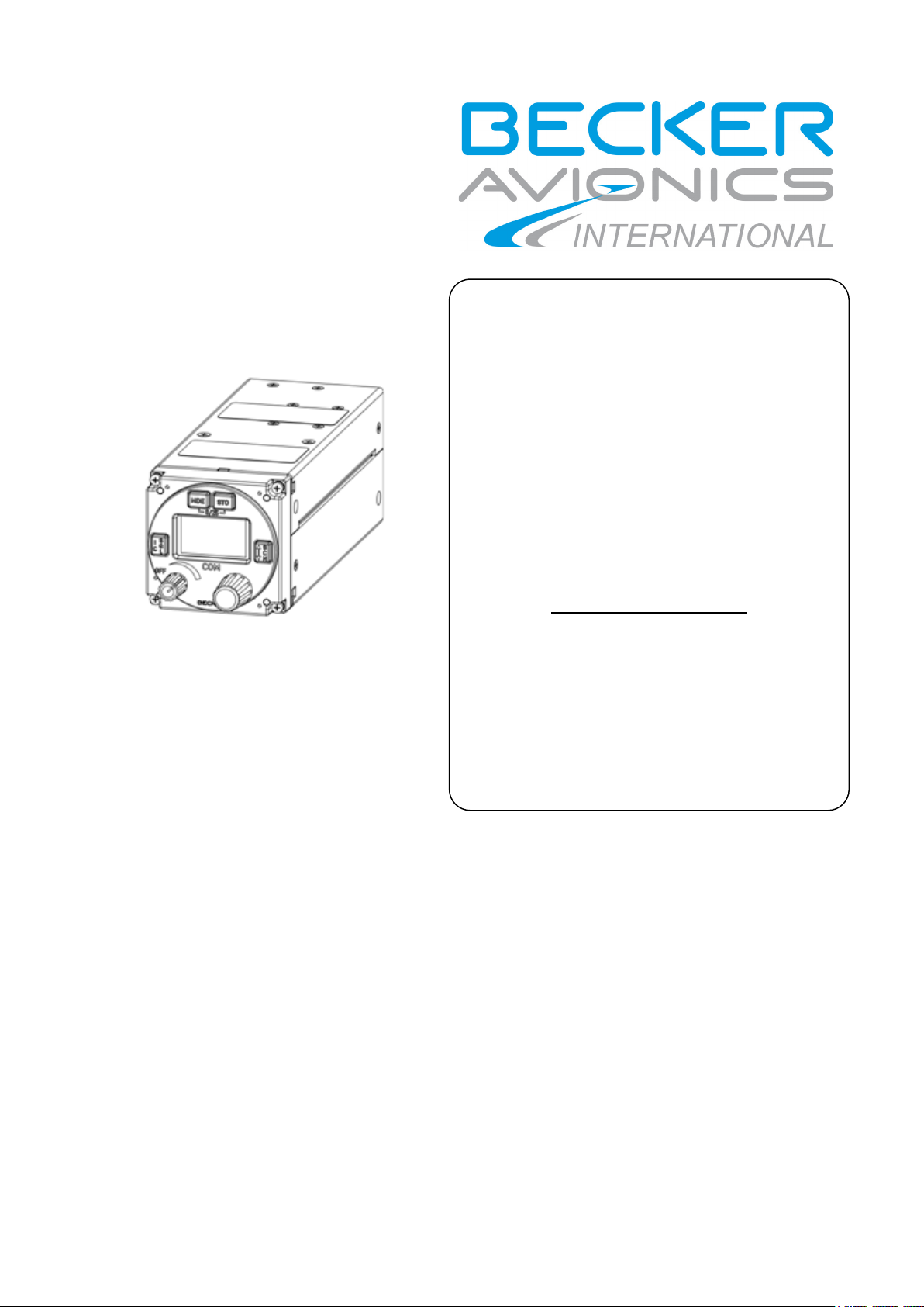
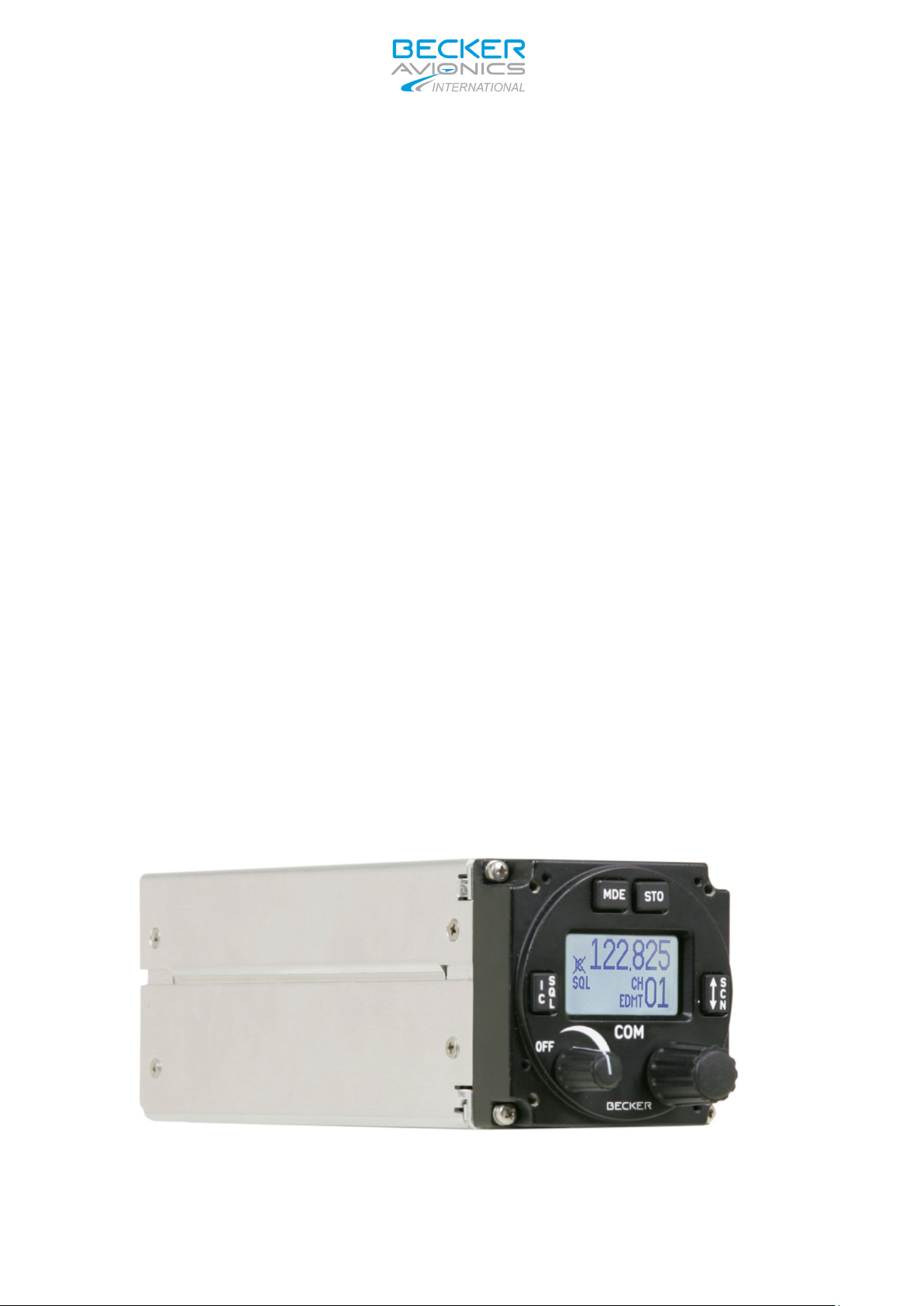
Available models:
GT6201-05 VHF Ground Transceiver, 6 Watt (at 11 …30.3 V/DC)
Article-No. 0637.351-923
GT6201-10 VHF Ground Transceiver, 10 Watt (at 24 …. 30.3 V/DC)
Article-No. 0637.361-923
Figure 1-1: GT6201-XX Single Block Transceiver; 58 mm (2 ¼ inch) standard
instrument cut-out
_________________________________________________________________________________________
Page 2 DV 17001.03 Issue 4 01/2015

Frequency (MHz)
(kHz)
Displayed Frequency
Mode
only Mode
118.0000
25
118.000
118.00
118.0083
8.33
118.010
N/A
118.0166
8.33
118.015
N/A
etc.
etc.
etc.
etc.
136.9750
25
136.975
136.97
136.9750
8.33
136.980
N/A
136.9833
8.33
136.985
N/A
136.9916
8.33
136.990
N/A
GT6201
1.4 Features Overview
Frequency Indication
A liquid crystal display (LCD) provides the frequency indication. The required operating frequency
is set by means of the rotary knob. The relation between the real operating frequency and the
displayed frequency is according to standard (ICAO Annex 10, Volume II). For an overview, refer to
the table below.
Operating
118.0000 8.33 118.005 N/A
118.0250 25 118.025 118.02
Audio Outputs
The GT6201 VHF Transceiver includes four fully configurable outputs:
• Headphone 1 output, rated output power is 300 mW into 75 Ohm, (with floating transformer
output)
Channel Spacing
8.33 / 25 kHz mixed
25 kHz
• Headphone 2 output, rated output power is 200 mW into 75 Ohm, (differential output DC
• Speaker output, rated output power is 4 W into 4 Ohm, (asymmetric AC-coupled output)
• LINE-OUT output intended for ground station use only. (asymmetric AC-coupled output)
Note: Headphone 2 and speaker output cannot be active at the same time
Mike Inputs
GT6201 has an input for dynamic microphone (DYN_MIKE) and an input for standard microphone
(STD_MIKE).
The GT6201 VHF Transceiver provides four microphone inputs:
• Standard microphone input 1 (STD_MIKE1),
• Standard microphone input 2 (STD_MIKE2),
• Standard microphone input 3 (STD_MIKE3),
• Dynamic microphone input (DYN_MIKE).
Each input is able to operate with one single microphone or with two microphones of the same type
connected in parallel.
_________________________________________________________________________________________
DV 17001.03 Issue 4 01/2015 Page 3
coupled)

GT6201
AF Auxiliary Input
The AF auxiliary input is an interface to connect external audio (e.g. other radio services, musicplayer) to the transceiver. Interconnection of multiple external audio sources on this particular port
requires additional external decupling/isolation resistors. The external audio is audible only when
the transceiver is in the receive mode.
The individual audio volume is set directly at the particular external equipment.
Sidetone
The sidetone is available on the headphone output during transmission. The sidetone volume
automatically adapts to the intercom volume setting.
Squelch Operation
When enabled the squelch (muting) circuit suppresses weak signals. There are two kinds of
squelch methods implemented: carrier squelch and noise squelch. The carrier squelch depends on
received signal strength and is adjustable in the installation setup; the noise squelch depends on
detected signal to noise ratio and is adjustable in the user setup.
Memory Channels
The memory function allows storage of up to 99+9 frequencies. This memory can contain up to 99
user defined frequencies stored manually that can be labeled with channel numbers and assigned
text label.
Generally the last recently used (active) 9 frequencies are stored automatically as “LAST”
channels. If any of the last used frequencies is also stored in the 99 user channels and a text label
is attached, this text will appear on the display too.
Scan Mode
In scan mode a dual watch function is provided. The device is capable of monitoring frequencies on
two channels, active & preset simultaneously. The signal of the active frequency will always be
audible, since it will have priority at all times.
Illumination
The illumination of LCD and push buttons can be controlled either directly from the front panel via
the users menu or externally via the dimming input lines. If the external dimming is selected, the
illumination curve (brightness to voltage relation) can be adjusted in the installation setup.
LOW BATT Indication
The VHF transceiver monitors power supply voltage. If the supply voltage drops below the
adjustable threshold, the display indicates the message “LOW BATT”. If the power supply voltage
drops further, emergency operation mode is entered.
Emergency Operation
If the power supply voltage drops below 10.25 V, the VHF transceiver continues operation with
degraded performance. In case the power supply drops below 9.0V the unit is automatically
switched off.
Built-in Tests PBIT and CBIT
After power-up, the unit performs a self-test (power-up built-in test / PBIT). During PBIT the
transceiver displays “WAIT” and the corresponding software versions of both, the control head and
chassis module.
If faults are detected during PBIT, the error message “FAILURE, press any key” is displayed. If no
faults are detected the transceiver automatically activates the mode set before last power-off.
During normal operation a continuous built-in test (CBIT) permanently verifies the correct operation
of the unit. If a problem is detected during CBIT, an error message will be displayed.
_________________________________________________________________________________________
Page 4 DV 17001.03 Issue 4 01/2015

GT6201-10
10 Watt *
0…28 V DC
0…28 V DC
@ 12 VDC, VSWR=1:1
1.7A at 0%
@ 24 VDC, VSWR=1:1
1.25A at 0%
GT6201
Installation Setup
Via the installation setup the configuration of the installation parameters, such as mike sensitivity,
mike type selection, speaker enable/disable plus other parameters is available.
Service Mode
The service mode is a special configuration mode accessible via RS422 interface with a proprietary
serial data communication protocol. This mode is for use by authorized maintenance personnel
only.
1.5 Technical Data
1.5.1 Power Supply Data
For GT6201 units the following data applies:
Nominal supply voltage range ....................... 11.0 … 30.3 V
Extended supply voltage range ..................... 10.25 V … 32.2V
Emergency operation .................................... 9.0 V to 10.25 V
Dimming control ............................................ 0…14 V or 0…28 V
Typical Power Consumption
Nominal supply voltage range 11.0 … 30.3 V DC 11 … 30.3 V DC
Extended supply voltage range 10.25 … 32.2 V DC
Emergency operation 9.0 V 9.0 V
Dimming control
Typical current consumptions
Power off state @ 12 VDC ≤ 0.10 mA --
Power off state @ 24 VDC ≤ 0.10 mA ≤ 0.10 mA
GT6201-05
6 Watt
0…14 V DC or
10.25 … 32.2 V
DC
0…14 V DC or
Reception stand-by mode @ 12 VDC, panel backlight off ≤ 140 mA ≤ 140 mA
Reception stand-by mode @ 24 VDC, panel backlight off ≤ 80 mA ≤ 80 mA
Transmission mode
Transmission mode
_________________________________________________________________________________________
DV 17001.03 Issue 4 01/2015 Page 5
2.0A at 85%
--
--
1.5A at 85%
GT6201-10
10 Watt *
Frequency range
118.000 MHz to 136.9916 MHz
Channel spacing
8.33/25 kHz
Number of channels
2280 + 760
Storage temperature range
-55°C to +85°C
Operating temperature range
-20°C to +55°C
GT6201-XX
Front panel
61.2 mm x 61.2 mm
(front plate till end of antenna connector)
58 mm diameter (2
inch)
Material of Case
ALMg
Surface treatment
control head coated with black matt paint
Weight
645g
1.5.2 General Data
GT6201
*: 6 to 10 W TX power between 11 … 24 V/DC, 10 W at 24 V/DC and above.
1.5.3 Dimensions & Weight
Depth of unit
Mounting
GT6201-05
6 Watt
187.8 mm
(back panel) standard
1/4
_________________________________________________________________________________________
Page 6 DV 17001.03 Issue 4 01/2015

GT6201
(measured with psophometric filter)
Effective bandwidth
(8.33 kHz channel spacing)
Effective bandwidth
(25 kHz channel spacing)
≤ 6 dB
in range -101 dBm to -1 dBm
≤ 5%
at 90%, 50% of rated output power
Audio frequency response
(8.33 kHz channel spacing)
+2 dB / -4 dB 350 Hz to 2500 Hz
relative to 1000 Hz
Audio frequency response
(25 kHz channel spacing)
+2 dB / -4 dB 300 Hz to 3400 Hz
relative to 1000 Hz
Rated output power
for headphone 1 operation
≥ 300 mW into 75 Ohm
≥ 100 mW into 600 Ohm
Rated output power
for headphone 2 operation
≥ 200 mW into 75 Ohm
≥ 100 mW into 600 Ohm
50 mV to 8 V (adjustable) across 600
Ohm
GT6201
1.5.4 Receiver Data
≤ -101 dBm for a SINAD of 12 dB
(nominal)
Sensitivity
Squelch trigger level adjustable
AGC characteristic
Distortion
Audio Noise ≥ 40 dB at 90%
≤ -95 dBm for a SINAD of 12 dB
(under extended and extreme
environmental conditions)
±2.8 kHz
±8.5 kHz
at 30%, 50% of rated output power
≤ 10%
Rated output for speaker operation ≥ 4 W into 4 Ohm
Audio auxiliary input
Offset-Carrier operation N/A
1.5.5 Transmitter Data
GT6201-05 GT6201-10
Output power into 50 Ohm (with and without
modulation)
Frequency tolerance ≤ ±1 ppm
Duty cycle 120 sec (TX) : 480 sec (RX)
Type of modulation
≥ 6 W ≥ 10 W
6K80A3EJN
5K00A3EJN
Modulation capability ≥ 85%
Distortion ≤ 10%
_________________________________________________________________________________________
DV 17001.03 Issue 4 01/2015 Page 7
Part Number
Article Number
GT6201-10
0637.361-923
GT6201-05
0637.351-923
GT6201
GT6201
Audio frequency response
(8.33 kHz channel spacing)
Audio frequency response
(25 kHz channel spacing)
Dynamic microphone
(with compressor)
Standard microphone(s)
(with compressor)
FM deviation with modulation ≤ 3 kHz (</= 800Hz typically)
Sidetone Adjustable
Automatic shutdown of transmit mode
350 Hz to 2500 Hz relative to 1000 Hz
300 Hz to 3400 Hz relative to 1000 Hz
1 … 20 mV compressor starting point,
10 … 1000 mV compressor starting
120 sec (Factory configurable 30 sec …
-4 dB / +2 dB in band
≤ -25 dB above 3200 Hz
-4 dB / +2 dB in band
≤ -25 dB above 5000 Hz
adjustable
Input balanced, 140 Ω
Input range up to 20 dB above
compressor starting point.
point, adjustable
Input unbalanced, 110 Ω
Input range up to 20 dB above
compressor starting point.
120 sec)
1.5.6 Emergency Operation
Panel & Display Backlight ............................. switched off for saving BATT energy
TX Output Power ........................................... ≥ 2 W into 50 Ω (with modulation)
TX Modulation Depth ..................................... ≥ 50 %
RX Sensitivity................................................. ≤-93 dBm for a (S+N)/N ratio of 6 dB
1.5.7 Regulatory Compliance
Note: Unauthorized changes or modifications to the GT6201 VHF transceivers may
void the compliance to the required regulatory agencies and authorization for
continued equipment usage.
GT6201 complies with ETSI EN 300 676 regulations
_________________________________________________________________________________________
Page 8 DV 17001.03 Issue 4 01/2015

923
Dynamic Microphone
951
Speaker with housing and cables
882
Car mounting
953
Cable harness
950
Antenna
952
Antenna cable, length 2.5 m
950
GT6201-XX and GT6201-XX-R
GT6201-XX and GT6201-XX-R
GT6201
1.5.8 Accessories
Available accessories for GT6201 can be purchased with the following Article Numbers. The
connector kit or mounting kit as required for equipment installation is normally included in the
delivery of your purchased Transceiver. The following information is needed for spare part order.
Vehicle Kit VK4201
1PM012
1PL011
1E024
1K044
1A002
1KA003
Available Documentation:
Article-No.: 0892.424-
Article-No.: 0344.214-
Article-No.: 0524.352-
Article-No.: 0499.226-
Article-No.: 0892.513-
Article-No.: 0267.015-
Article-No.: 0267.082-
Operating Instructions (DV 17001.03)
Maintenance and Repair Manual (DV 17001.04)
Article No.: 0640.093-071
Article No.: 0640.107-071
_________________________________________________________________________________________
DV 17001.03 Issue 4 01/2015 Page 9

GT6201
Blank Page
_________________________________________________________________________________________
Page 10 DV 17001.03 Issue 4 01/2015
 Loading...