

Page 1

B-Tronic EasyControl
EC5401B
en
Assembly and Operating Instructions
Wall/hand-held transmitter, 1-channel,
bidirectional
Important information for:
• Fitters / • Electricians / • Users
Please forward accordingly!
These instructions must be kept safe for future reference.
4035 630 003 0f05/12/2018
Becker-Antriebe GmbH
Friedrich-Ebert-Straße 2-4
35764 Sinn/Germany
www.becker-antriebe.com
Page 2

Table of contents
General ................................................................................................... 3
Warranty ................................................................................................. 3
Safety instructions ................................................................................... 4
Intended use ........................................................................................... 5
Explanation of displays and buttons........................................................... 6
Normal/master mode ............................................................................... 8
Programming the first transmitter.............................................................. 9
Querying/Changing the receiver mode .....................................................10
Programming more transmitters ..............................................................12
Deleting transmitters............................................................................... 14
Changing the direction of rotation of B-Tronic products .............................16
Setting the limit positions of B-Tronic tubular drives...................................17
Upper stop to lower stop ...................................................................17
Upper point to lower point .................................................................18
Upper stop to lower point ..................................................................19
Upper point to lower stop ..................................................................19
Deleting the limit positions of B-Tronic tubular drives .................................20
Performing the programming run on B-Tronic radio receivers.....................21
Deleting the programming run on B-Tronic radio receivers.........................22
Intermediate positions/tilt positions ..........................................................23
Memory function.....................................................................................25
Upper anti-freeze mechanism ..................................................................26
Activating/Deactivating upper anti-freeze mechanism .........................27
Fly screen protection function ..................................................................27
Activating/deactivating repeater mode .....................................................28
Reset the transmitter to the factory setting................................................29
Clean-up function for B-Tronic products...................................................30
Changing batteries..................................................................................31
Wall bracket............................................................................................32
Cleaning.................................................................................................32
Technical data ........................................................................................33
What to do if...?.......................................................................................33
Simplified EU declaration of conformity.....................................................34
2
Page 3
General
You can operate drives and control units with bidirectional KNX radio with this
transmitter.
This device is exceptionally easy to use.
Please observe these Assembly and Operating Instructions when installing
and setting up the equipment.
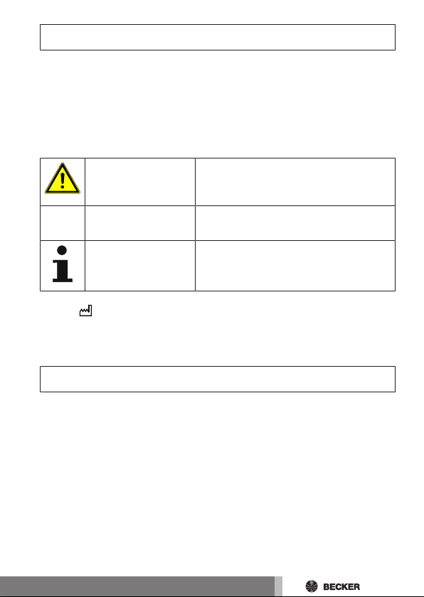
Explanation of pictograms
CAUTION
ATTENTION
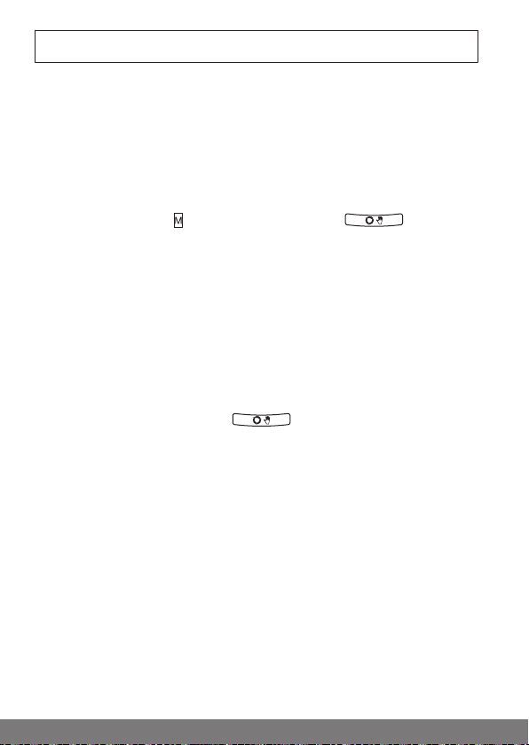
You will find the current status on the type plate according to the following
symbol:
The description of the acknowledgement can be found in the relevant instructions for the receiver.
CAUTION indicates a hazardous situation
which, if not avoided, could result in injury.
ATTENTION indicates measures that must
be taken to avoid damage to property.
Denotes user tips and other useful information.
Warranty
Structural modifications and incorrect installation which are not in accordance
with these and our other instructions can result in serious injuries, e.g., crushing of limbs. Therefore, structural modifications may only be carried out with
our prior approval and strictly in accordance with our instructions, particularly
the information contained in these Assembly and Operating Instructions.
Any further processing of the products which does not comply with their intended use is not permitted.
The end product manufacturer and fitter have to ensure that all the relevant
current statutory, official and, in particular, EMC regulations are adhered to
during utilisation of our products, especially with regard to end product manufacture, installation and customer advice.
3
Page 4
Safety instructions
General information
• Please keep the instructions safe!
• Only use in dry rooms.
• Only use unmodified original parts from the control unit manufacturer.
• Keep children away from control units.
• Observe all pertinent country-specific regulations.
• Dispose of exhausted batteries properly. Only replace batteries with the
identical type (see Technical data).
Caution
• Keep people out of the system’s range of travel.
• If the system is controlled by one or more transmitters,
the system’s range of travel must always be visible during
operation.
• Device contains small parts that can be swallowed.
4
Page 5

Intended use
The transmitter described in these instructions may only be used for operating
suitable drives and control units with bidirectional KNX radio. You can operate
either one group or a number of groups of devices with this transmitter.
• Please note that radio-controlled systems may not be used in areas with
a high risk of interference (e.g. hospitals, airports).
• The remote control is intended solely for use with equipment and sys-
tems in which malfunctions in the transmitter or receiver would not pose
any risk to persons, animals or property, or which contain safety devices
to eliminate such risks.
• The operator is not protected from interference from other telecommu-
nications systems and terminal equipment (e.g. even from radio-controlled systems which are properly operated in the same frequency
range).
• Only connect radio receivers to devices and systems approved by the
manufacturer.
• Ensure that the control unit is not installed or operated
close to metal surfaces or magnetic fields.
• Radio-controlled systems transmitting on the same frequency may cause reception interference.
• Note that the range of the radio signal is limited by legislation as well as by design.
5
Page 6
2
4
5
1
11
10
9
8
7
6
3
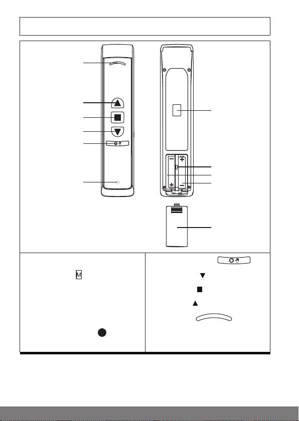
Explanation of displays and buttons
1 Wall bracket receptacle
2 Master button
3 Type plate
4 Batteries
5 Battery compartment cover
6 Programming button (behind
the logo)
6
7 Changeover switch
8 DOWN button
9 STOP button
10 UP button
11 Status LED
Page 7
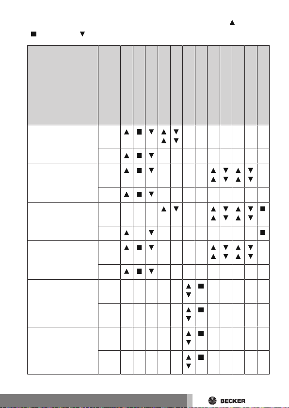
Functional overview of the control buttons UP ( ), STOP
( ), DOWN ( )
1
1
1
1
2
Function
Roller shutter <1s
>1s
Screen <1s
>1s
Blind <1s
>1s
Roof window <1s
>1s
ON/OFF <1s
>1s
Pulse <1s
>1s
UP
STOP
DOWN
Button actuation
ON
OFF
Touch mode UP
Touch mode DOWN
STOP/STEP*
Tilt position I*
Tilt position II*
Intermediate position I*
Intermediate position II*
*1) If present.
*2) With a STOP command, the STEP is always made in the UP direction
7
Page 8
Normal/master mode
The transmitter can be operated in two modes:
• Normal mode (normal operation) The commands that are issued apply
to all the receivers of a channel.
• Master mode (Setting mode for all B‑Tronic products) The commands
issued apply exclusively to one selected receiver of a channel.
The normal mode is set at the factory.
Activating master mode
Press the master button until the changeover button flashes
green once per second. This flashing will continue as long as you remain in
master mode.
By pressing the master button again, the programmed receiver is selected, or
the programmed receivers are selected in sequence.
The selected receiver confirms.
You can now make the various settings that are only available in master mode.
When all the desired settings have been made at this receiver, you can press
the master button again to select the next receiver for programming.
Leaving master mode
There are two ways to leave master mode:
1. Press the changeover button
2. Master mode is automatically closed once 2 minutes have gone by
without a button being pushed
8
Page 9
Programming the first transmitter
The receiver mode must always be set appropriately for the
receiver. Roller shutter/venetian blind is the factory setting.
Putting the receiver into programming mode
Follow the Assembly and Operating Instructions for the receiver.
• Switch off the power supply to the receiver for 5 seconds, then switch it
back on
or
• Operate the programming button or the radio switch of the receiver.
The receiver is now in programming mode for 3 minutes.
Programming transmitters
Please make sure that only one receiver is in programming
mode at any time. It is not possible to program/clear multiple
receivers at the same time.
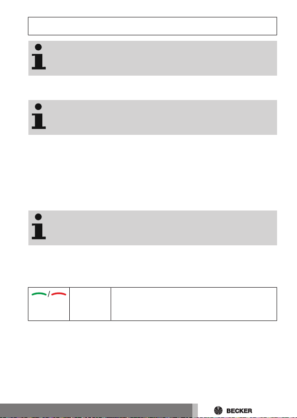
Press the transmitter's programming button while programming mode is active, until the receiver confirms successful programming. The status LED
flashes yellow during the programming process.
The programming process is now complete.
Lights up
green /
red
Action completed successfully (green) or not successfully (red).
9
Page 10
Querying/Changing the receiver mode
The receiver mode must always be set appropriately for the
receiver. Roller shutter/venetian blind is the factory setting.
Querying the current receiver mode
There are different receiver modes. The receiver mode must always be set appropriately for the receiver (e.g. roller shutter/blind, dimmer/switch). Roller
shutter/venetian blind is the factory setting.
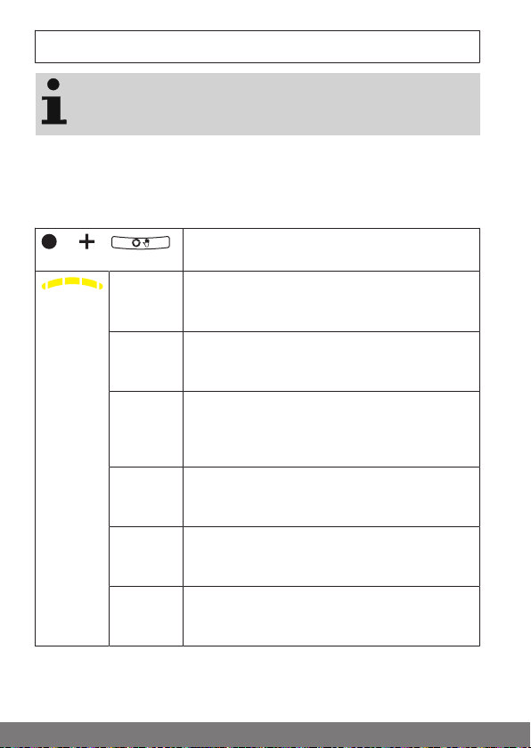
Briefly press the programming button, and then
the changeover button for 1 second.
Flashes
yellow
once
Flashes
yellow
twice
Flashes
yellow
three
times
Flashes
yellow four
times
Flashes
yellow five
times
Flashes
yellow six
times
Receiver mode roller shutter
Receiver mode dimmer
Receiver mode switch
Receiver mode venetian blind
Receiver mode screen
Receiver mode roof window
10
Page 11
Changing to the desired receiver mode
The current receiver mode is first indicated through the display code.
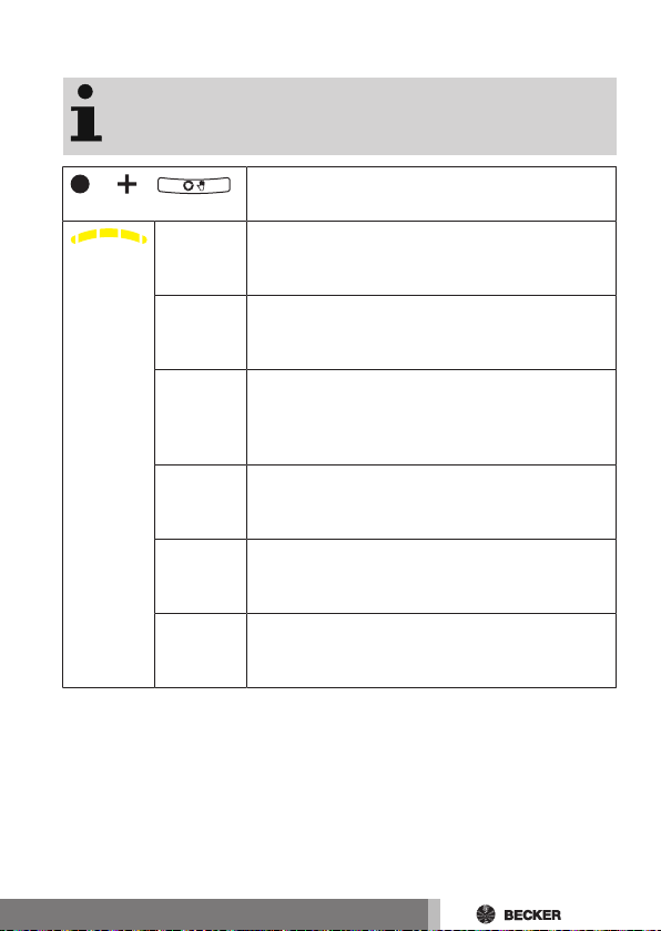
Briefly press the programming button, and then
the changeover button for 5 seconds.
Flashes
yellow
once
Flashes
yellow
twice
Flashes
yellow
three
times
Flashes
yellow four
times
Flashes
yellow five
times
Flashes
yellow six
times
Repeat this procedure until the desired receiver mode has been selected.
Receiver mode roller shutter
Receiver mode dimmer
Receiver mode switch
Receiver mode venetian blind
Receiver mode screen
Receiver mode roof window
11
Page 12

Programming more transmitters
The receiver mode must always be set appropriately for the
receiver. Roller shutter/venetian blind is the factory setting.
Programming more B-Tronic transmitters in the BTronic receiver
Put the receiver into programming mode in one of the three possible ways.
Please make sure that only one receiver is in programming
mode at any time. It is not possible to program/clear multiple
receivers at the same time.
Putting the B-Tronic receiver into programming mode with a programmed B‑Tronic transmitter
Put the transmitter into master mode.
Select the receiver by pressing the button until the desired receiver confirms.
All the following settings will then only be executed for this device.
Press the programming button of the programmed transmitter.
▻ The receiver confirms.
► The receiver goes into the programming
mode for 3 minutes
12
Putting the B-Tronic receiver into programming mode by switching on the power
Switch on the power.
► The receiver goes into the programming
mode for 3 minutes
Page 13

Putting the B-Tronic receiver into programming mode with the radio switch
Switch the radio switch to the inside position. If
the radio switch is already in this position, switch it
to the outside and back to the inside position.
► The tubular drive goes into the programming
mode for 3 minutes
Press the programming button for 3 seconds.
The LED flashes green.
► The receiver goes into the programming
mode for 3 minutes
When the receiver is in programming mode, proceed as follows:
Now press the programming button of the new
transmitter.
▻ The receiver confirms.
► The programming process is now complete.
Lights up
green /
red
Action completed successfully (green) or not successfully (red).
Programming more B-Tronic transmitters in a KNX RF
compatible receiver from another manufacturer
Please find the appropriate description on our website.
Programming more KNX RF compatible transmitters
from another manufacturer in a B-Tronic receiver
Please find the appropriate description on our website.
13
Page 14

Deleting transmitters
Deleting from B-Tronic receivers with two B-Tronic
transmitters
Put a programmed transmitter, other than the one that is to be deleted, into master mode.
Select the device by pressing the button until the desired device confirms.
All the following settings will then only be executed for this device.
While the transmitter is in master mode, the sym-
Changes
from
green to
yellow
Flashes
yellow
bols on the changeover button flash green once
per second.
Now press the programming button, until the
status LED changes from green to yellow, and the
receiver confirms.
Press the programming button, until the status
LED flashes yellow and the receiver confirms.
Now press the programming button of the trans-
mitter to be deleted until the receiver confirms.
► The transmitter is now deleted from the re-
ceiver.
14
Lights up
green /
red
Action completed successfully (green) or not successfully (red).
Page 15

Deleting from B-Tronic receivers with one B-Tronic
transmitter
The last or only transmitter in a receiver can be deleted using
the following deletion sequence. To program new transmitters, the receiver must again be put into programming mode.
Put the transmitter into master mode.
Select the device by pressing the button until the desired device confirms.
All the following settings will then only be executed for this device.
While the transmitter is in master mode, the sym-
Changes
from
green to
yellow
Flashes
yellow
bols on the changeover button flash green once
per second.
Now press the programming button, until the
status LED changes from green to yellow, and the
receiver confirms.
Press the programming button, until the status
LED flashes yellow and the receiver confirms.
Now press the changeover button to leave master
mode.
Now press the programming button until the receiver confirms.
► The transmitter is now deleted from the re-
ceiver.
Lights up
green /
red
Action completed successfully (green) or not successfully (red).
15
Page 16

Deleting a B-Tronic transmitter from a KNX RF
compatible receiver from another manufacturer
Please find the appropriate description in the instructions for the receiver or
on our website.
Changing the direction of rotation of B-
Tronic products
Check the direction of rotation before setting the limit positions. The shading
solution must move in the correct direction when the UP or DOWN buttons are
pressed.
If this is not the case, please carry out the following steps to change the direction of rotation:
No limit positions must be programmed. Delete the limit positions if necessary.
Put the transmitter into master mode.
Select the receiver by pressing the button until the desired receiver confirms.
First press the programming button and, within
the next 3seconds, press both the UP and DOWN
buttons for 3seconds.
▻ The receiver confirms.
Check the running direction again.
16
Page 17

Setting the limit positions of B-Tronic tubular
drives
Upper stop to lower stop
Put the transmitter into master mode.
Select the tubular drive by pressing the button until the tubular drive confirms.
All the following settings will then only be executed for this device.
Open to the permanent upper stop.
▻ The tubular drive switches off automat-
ically.
Then close to the permanent lower stop.
▻ The tubular drive switches off automat-
ically.
► The limit positions are now set.
17
Page 18

Upper point to lower point
Put the transmitter into master mode.
Select the tubular drive by pressing the button until the tubular drive confirms.
All the following settings will then only be executed for this device.
There is no shading solution length adjustment with this limit
position setting.
Open to the desired upper limit position.
Press the programming button and, within 1
second, also press the UP button and hold the two
buttons down.
▻ The receiver confirms.
Then close to the desired lower limit position.
Press the programming button and, within 1
second, also press the DOWN button and hold the
two buttons down.
▻ The receiver confirms.
► The limit positions are now set.
18
Page 19

Upper stop to lower point
Put the transmitter into master mode.
Select the tubular drive by pressing the button until the tubular drive confirms.
All the following settings will then only be executed for this device.
Open to the permanent upper stop.
▻ The tubular drive switches off automat-
ically.
Then close to the desired lower limit position.
Press the programming button and, within 1
second, also press the DOWN button and hold the
two buttons down.
▻ The receiver confirms.
► The limit positions are now set.
Upper point to lower stop
Put the transmitter into master mode.
Select the tubular drive by pressing the button until the tubular drive confirms.
All the following settings will then only be executed for this device.
Open to the desired upper limit position.
Press the programming button and, within 1
second, also press the UP button and hold the two
buttons down.
▻ The receiver confirms.
Then close to the permanent lower stop.
▻ The tubular drive switches off automat-
ically.
► The limit positions are now set.
19
Page 20

Deleting the limit positions of B-Tronic
tubular drives
Attention
When one or both of the limit positions are deleted, all the
other set functions (e.g. intermediate position) are deleted
as well.
Once set, the limit positions can only be deleted using master mode. Deleted limit positions are displayed on the limit
position status indicator.
Deleting individual limit positions
Put the transmitter into master mode.
Select the tubular drive by pressing the button until the tubular drive confirms.
All the following settings will then only be executed for this device.
Open/close to the limit position to be deleted.
Press the programming button and, within the
next 1 second, press the STOP button at the same
time and hold the two buttons down for 5 seconds.
▻ The receiver confirms.
► The limit position is now deleted.
20
Page 21

Deleting both limit positions
1x
Put the transmitter into master mode.
Select the tubular drive by pressing the button until the tubular drive confirms.
All the following settings will then only be executed for this device.
Open/close the shading solution to a point
between the limit positions.
Press the programming button and, within 1
second, press the STOP button at the same time
and hold the two buttons down for 5 seconds.
▻ The receiver confirms.
► The limit positions are now deleted.
Performing the programming run on B-
Tronic radio receivers
Feedback is disabled and it is not possible to program the intermediate positions until the programming run has been
performed.
Put the transmitter into master mode.
Select the receiver by pressing the button until the required receiver confirms.
All the following settings will then only be executed for this device.
Open to the desired upper limit position.
Press the programming button and, within 1
second, also press the UP button and hold the two
buttons down.
▻ The receiver confirms.
Then close to the desired lower limit position.
21
Page 22

1x
Press the programming button and, within 1
2x
second, also press the DOWN button and hold the
two buttons down.
▻ The receiver confirms.
► The programming run is completed.
Deleting the programming run on B-Tronic
radio receivers
Put the transmitter into master mode.
Select the receiver by pressing the button until the required receiver confirms.
All the following settings will then only be executed for this device.
Open/close the shading solution to a point
between the limit positions.
Press the programming button and, within the
next 1 second, press the STOP button at the same
time and hold the two buttons down for 5
seconds.
▻ The receiver confirms.
► The programming run is now deleted.
22
Page 23

Intermediate positions/tilt positions
The intermediate positions or tilt positions are freely selectable positions for the shading solution or blind between the
two limit positions. Each travel button can be assigned one
intermediate position/tilt position. Both limit positions must
be set before an intermediate position is set.
When both or individual limit positions are deleted, both intermediate positions/tilt positions are deleted as well.
With external receivers it is possible to overwrite in any position without deleting the previous position.
Setting the desired intermediate position
Open/close the shading solution to the desired intermediate position.
Press the STOP button and, within 3 seconds, also
press the desired travel button and hold the two
buttons down.
▻ The receiver confirms.
► The intermediate position is now saved.
Setting the desired tilt position when operating blinds
Move the blind from the upper limit position to the
position at which you wish to attach the tilt.
Press the STOP button repeatedly until the desired tilt position is reached.
Press the STOP button and, within 3 seconds, also
press the desired travel button and hold the two
buttons down.
▻ The receiver confirms.
► The tilt position is now saved.
23
Page 24

Travelling to the desired intermediate position/tilt
position
Press the travel button for the desired intermediate position/tilt position twice within one second.
► The shading solution runs to the intermedi-
ate position/tilt position assigned to the
travel button.
Lights up
green /
red
Action successful with all receivers (green) or not
successful with at least one receiver (red).
Deleting the desired intermediate position/tilt position
Press the travel button for the desired intermediate position/tilt position twice within one second.
▻ The shading solution runs to the inter-
mediate position/tilt position assigned
to the travel button.
Press the STOP button and, within 3 seconds, also
press the travel button assigned to the intermediate position/tilt position and hold the two buttons
down.
▻ The receiver confirms.
► The intermediate position/tilt position is now
deleted.
24
Page 25

Memory function
Every B-Tronic radio receiver for roller shutter and blind installations can save
switching times for UP and DOWN movement.
In the " " operating mode, this movement is repeated every 24 hours.
It does not matter what position the / changeover button is in when programming the switching time. Previously stored switching times are overwritten.
Lights up
green
Lights up
green
Light up
green
Switching from the " " operating mode to the " " operating
mode must take place via the device on which the automatic
command was programmed. If automatic commands have
been programmed by several devices independently, they
have to be changed to " " separately.
Roller shutter/all roller shutters are in automatic
mode
Roller shutter/all roller shutters are in manual
mode
Roller shutters are in different modes
Programming the run times
1. The tubular drive must be in the upper limit position to program the
DOWN run time, and must be in the lower limit position for the UP run
time.
2. Wait for the time you wish the automatic drive command to be executed.
3. At the desired time, press and hold the relevant direction button until the
tubular drive briefly stops after approx. 6seconds and then continues to
the limit position.
4. Release the direction button.
The tubular drive has saved the current time for this direction of travel.
Proceed in exactly the same way with the other direction of movement.
25
Page 26

Deleting the run times
When deleting, both run times are always deleted.
To delete the UP and DOWN run time, press the STOP button for 10 seconds.
The receiver confirms. The run times are now deleted.
Upper anti-freeze mechanism
The upper anti-freeze mechanism (if present in the receiver) helps to prevent
the roller shutter from freezing in the upper limit position, as the roller shutter
stops just before the upper stop. The distance from the upper stop is automatically cyclically checked and, if necessary, corrected.
The upper anti-freeze mechanism is deactivated on delivery.
Both limit positions must be set before the anti-freeze mechanism can be activated.
The anti-freeze mechanism only works if a permanent stop is
set at the upper limit position of the roller shutter. The antifreeze mechanism is not visible until the shading solution has
reached the upper stop from the lower limit position 3 times
in succession.
When both or individual limit positions are deleted, this set
function is deleted as well.
26
Page 27

Activating/Deactivating upper anti-freeze mechanism
Put the transmitter into master mode.
Select the receiver by pressing the button until the desired receiver confirms.
All the following settings will then only be executed for this device.
Open the shading solution to the upper limit position.
Then re-press the programming button and also the
STOP and UP buttons for approx. 5seconds.
▻ The receiver confirms.
Fly screen protection function
If the fly screen protection function is activated (if available in the receiver),
obstacle detection is activated after a revolution of the barrel of approx. 140°
from the upper limit position. If the roller shutter curtain meets an opened fly
screen door, the drive stops and returns to the upper limit position.
The fly screen protection function is deactivated on delivery.
Both limit positions must be set before the fly screen protection function can
be activated.
When both or individual limit positions are deleted, this set
function is deleted as well.
Activating/deactivating the fly screen protection
function
Put the transmitter into master mode.
Select the receiver by pressing the button until the desired receiver confirms.
All the following settings will then only be executed for this device.
27
Page 28

Open the shading solution to the upper limit position.
Then press the teaching button and also the STOP
and UP buttons for approximately 5 seconds.
▻ The receiver confirms.
Activating/deactivating repeater mode
Put the transmitter into master mode.
Select the receiver by pressing the button until the desired receiver confirms.
All the following settings will then only be executed for this device.
Press the programming button, and then the
changeover button as well, keeping them
pressed. The current repeater mode is displayed.
Continue holding the buttons down for 5seconds
to change over.
The receiver confirms.
1x Repeater mode activated
2x Repeater mode deactivated
28
Page 29

Reset the transmitter to the factory setting
Attention
If the transmitter is reset to factory settings, master mode
will no longer give you access to the receiver or receivers in
which the transmitter has been programmed. Please only
make this setting when the batteries are new.
Open the cover of the battery compartment.
Take out the batteries.
Then reinsert the batteries in the correct orientation, and then within one
second press the master button for at least five seconds, until the transmitter confirms. The status LED flashes yellow while the command is being
executed.
Lights up
green /
red
If the master button is released while the status LED is
flashing yellow, the procedure is cancelled.
Action completed successfully (green) or not successfully (red).
29
Page 30

Clean-up function for B-Tronic products
All receivers that are programmed and no longer present can be cleared with
the clean-up function.
The clean-up function is always applied to the selected channel. The switching commands sequence must be carried out
in quick succession. B-Tronic products that were temporarily
unreachable during the process should be reprogrammed.
Select the desired channel.
Put the transmitter into master mode.
1 second
1 second
6 seconds
30
Press the programming button for 1 second.
Press the programming button again for 1
second.
Press the programming button again for 6
seconds.
The LED flashes yellow quickly for about 3
seconds, then changes to green.
Now press the changeover button to leave
master mode.
Page 31

Changing batteries
You will find the appropriate battery type in the "Technical
data" chapter.
Flashes
yellow
If the status LED gives slow yellow flashes while
the button is being pressed, the batteries are almost empty, and must be exchanged as soon as
possible.
If the status LED no longer lights up when a button
is pressed, the batteries are empty.
1. Open the cover of the battery
compartment.
2. Take out the batteries.
3. Insert the new batteries correctly.
4. Close the cover of the battery
compartment.
31
Page 32

Wall bracket
4,2
49
1. 2.
3.
1. Check that the transmitter and
receiver are working properly
before mounting in the desired
position.
2. Fasten the bracket to the wall
using the two enclosed screws.
3. Now push the screw covers into
the screw holes.
Cleaning
Only clean the device with a suitable cloth. Do not use aggressive cleaning
agents that may damage the surface.
32
Page 33

Technical data
Rated Voltage 3 V DC
Battery type LR 03 (AAA)
Degree of protection IP 20
Permissible ambient temperature -10 to +55 °C
Maximum emitted transmission output ≤ 25 mW
Radio frequency 868.3 MHz
Max. number of receivers 32
The maximum transmitter range on and in the building is up to 25m, and up to
350m in the open.
What to do if...?
Problem Remedy
Receiver is not responding.
Receiver is not responding to the master
button.
Status LED flashes yellow
Insert new batteries.
Insert batteries correctly.
Reduce distance from receiver.
Program transmitter.
Check the receiver.
Insert new batteries.
Receiver does not run in
a 24-hour rhythm.
Run times deviate from
those programmed.
.
Switch to .
Program switching times.
Power failure at receiver. Re-program switching
times.
33
Page 34

Problem Remedy
Status LED flashes red
for 3 seconds
after operating one of
the , , or buttons.
Status LED lights up red
for 3 seconds
after operating one of
the , , or buttons.
Function cannot be set. Check the functionality in the receiver.
Check the path for an obstacle.
Reduce distance from receiver.
Check the batteries.
Check the power supply at the receiver.
Simplified EU declaration of conformity
Becker-Antriebe GmbH hereby declares that this radio control system complies with Directive 2014/53/EU.
The full text of the EU declaration of conformity is available at the following
web address:
www.becker-antriebe.com/ce
Subject to technical changes without notice.
34
Page 35

35
Page 36

 Loading...