

Becker DVT 3.60, DVT 3.80, DVT 3.100, KVT 3.60, DVT 3.140 Operating Instructions Manual
...Page 1
l
COMBINED FLUID PRODUCTS COMPANY
● Vacuum and Compressed Air Specialists ● Since 1975
Tel: 800-521-2083 ● Fax: 847-540-0513 ● Email: sales@combinedfluidproducts.com ● Online Orders/Parts: www.CFPWarehouse.com ● Web: www.combinedfluidproducts.com
Vacuum pumps • Compressors
Application
These operating instructions apply to:
-Pressure vacuum pumps DVT 3.60-3.140
-Vacuum pumps KVT 3.60, 3.80, 3.100, 3.140
-Compressors KDT 3.60, 3.80, 3.100, 3.140
Safety Regulations
on Regulations VBG 16, Compressors, in particular Section IIIc "Installation” and IV "Operation”
plus VBG 4 "Electrical equipment and tools”.
Pumps may only be converted or modified after
approval by the manufacturer.
Please comply with Accident Preventi-
Application
The pumps can be used to generate a vacuum
(KVT), overpressure (KDT) or combined (DVT).
Inlet air must be standard dry atmospheric air. Do
not use for pumping toxic or inflammable sustances.
The pumps work oil-free. Prevent suction of oil mist.
of 800 m above sea level.
The specification is valid up to a height
Transport and storage
Store pump in a dry area. Prevent condensation
caused by vapour.
Lift and transport only by using the ring screws.
Installation
It is recommended to install the radial compressor with easy access for maintenance.
Clearance between compressors and adjacent
walls should be no less than 10 cm of free space
in order to ensure sufficient air flow for cooling.
DVT / KVT / KDT 3.60-3.80-3.100-3.140 0001 05/2000
DVT / KVT / KDT
3.60-3.80-3.100-3.140
Operating Instructions
Rotary vane vacuum pumps/compressors,
oilfree running, air-cooled
Contact Gebrüder Becker prior to installation
under noise insulation canopies.
Ambient temperatures must not exceed 45°C.
Connection and installation
Ensure correct dimensions (see Table) and clean
pipelines. Keep connections free from oil, grease,
water and any other contamination. With pipelines exceeding 5 m in length we recommend the
installation of non-return valves.
Keep connections free from oil, grease, water
and other contaminants.
Remove end caps at DA and SA. Do not connect
to pipeline yet.
Do not operate the compressor without safety
equipment against excessive pressure (for maximum values see rating plate). In case of permitted compression end pressures of more than 1
bar additionally connect a pressure meter and
mark end pressure.
Maintenance
Maintain pump regularly to achieve the best operating results. Maintenance intervals will depend
on the pump´s use and ambient conditions.
mains plug from socket to avoid unintentional restarting.
Before commencing maintenance, remove
Motor connection
Connect the radial compressor to the electricity supply
observing all applicable safety regulations. Comply with
EN 60204 T1.
Connect motor based on connecting diagram (in terminal box) or ready-made plugs. This work should be carried out by an experienced electrician only. Check for
connecting voltage and frequency.
Install motor circuit-breaker with Main switch and
set to nominal motor current. (For data see motor
rating plate).
Avoid switching of more than 10 times per hour.
Briefly start motor and check rotation
(arrow on casing). Exchange phases if rotation is
incorrect.
Commissioning
Connect pressure line at DA and inlet line at SA.
Set vacuum control valve VR or pressure control valve
DR to operating values (for values see table).
peratures at the compressors: Allow the pump
parts to cool before disassembly.
enclosure cover GD. Clean depending on dust accumulation. Blow out filter from inside to outside.
Replace blocked, oily or greasy cartridges.
Additional filters are available for operation in very dusty
environment.
compressed air.
The vanes are subject to wear due to abrasion from
the walls of the enclosure.
hours or annually (for minimum widths see Table).
Remove side cover SD for this.
On replacement blow out enclosure by dry compressed
air.
Air compression will generate high tem-
The filter cartridges are inserted behind the
Blow out dirt in cooling air channels KK by
Check vane width every 3000 operating
Replace the grease loss in the rolling bearing due
to disassembly - 2g 'Amblygon 15/2' grease in
total.Grease is to be found behind GB or with
included grease gun.
DVT/KVT/KDT3.60-3.80:The roller bearings are
prelubricated for life and will not require maintenance.
DVT/KVT/KDT3.100-3.140:Grease Roller bearings
at A and B after 2,000 hours of operation at both
of the grease nippels while the compressor is
running (3.100: 5g and 3.140: 7g).
Replace by original roller bearings only.
Repairing
Please return to Gebr. Becker.
D V T / K V T / K D T 3.60-3.80-3.100-3.140
Page 2
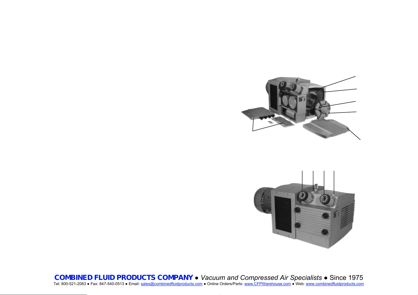
Tabelle-Table-Tableau-Tabella-Tabla
COMBINED FLUID PRODUCTS COMPANY
● Vacuum and Compressed Air Specialists ● Since 1975
Tel: 800-521-2083 ● Fax: 847-540-0513 ● Email: sales@combinedfluidproducts.com ● Online Orders/Parts: www.CFPWarehouse.com ● Web: www.combinedfluidproducts.com
DVT/KVT/KDT . . . . .3.60 . . . . . . . .3.80 . . . . . . . .3.100 . . . . . . .3.140
Anschlußleitung bis 2m / 2m bis 10m . . .1" / 1 1/2" . . . .1" / 1 1/2" . . . .1 1/2" / 2" . . . .1 1/2" / 2"
Pipework up to 2m / 2m up to 10m
Tuyauterie jusqu’à 2m / de 2m jusqu’à 10m
Tubazione fino a 2m / da 2m fino a 10m
Tubo de conexión hasta 2m / de 2 a 10m
Schieber-Mindestbreite [mm] . . . . . . . . . . . . .26 . . . . . . . . . .26 . . . . . . . . . .26 . . . . . . . . . .32
Width of vanes, min. [mm]
Largeur palettes, min. [mm]
Larghezza palette min. [mm]
Ancho mínimo de paletas [mm]
Volumenstrom bei 50/60 Hz [m3/h] . . . . . . .55/66 . . . . . . .70/82 . . . . . . .98/112 . . . . . .132/154
Air flow at 50/60 Hz [m3/h]
Débit d’air à 50/60 Hz [m3/h]
Capacità aria a 50/60 Hz [m3/h]
Caudal volumétrico de aire con 50/60 Hz [m3/h]
Länge ohne Motor [mm]/Breite [mm] . . . . .448/353 . . . . .448/353 . . . . .563/470 . . . . .563/470
Length without motor [mm]/Width [mm]
Longeur sans moteur [mm]/Largeur [mm]
Lunghezza senza motore [mm]/Larghezza [mm]
Longitud sin motor [mm]/Ancho [mm]
Höhe [mm] . . . . . . . . . . . . . . . . . . . . . . . . . .328 . . . . . . . . .328 . . . . . . . . .336 . . . . . . . . .336
Height [mm]
Hauteur [mm]
Altezza [mm]
Altura [mm]
Ventilregelbereich . . . . . . . . . . . . . . . . . . . . . . . . . . . . DVT +/- 0,6 bar . . . . . . . . . . . . . . . . .
Regulation range valves
Plage de régulation vannes KVT -0,90
Campo di regolazione vavole . . . . . . . . . . . . . . . . . . . . . . . . . . . . . . . . . . . . . . . . . . . .KDT +0,50/1,50
bar
Margen de regulación de válvula
Schalldruckpegel [db(A)] DVT . . . . . . . .74 . . . . . . . . . .75 . . . . . . . . . .77 . . . . . . . . . .78
Acoustic pressure level [db(A)]
Niveau de pression acoustique [db(A)]
Livello di pressione acustica [db(A)]
Nivel de pressión acústica [db(A)]
Technische Änderungen vorbehalten
Right of modifications reserved
Sous réserve des modifications
Sotto riserva di modificazioni
Salvo modificaciones técnicas
DVT / KVT / KDT 3.60-3.80-3.100-3.140 0002 05/2000
A
KK
B
SD
GD
GB
DA
DR
VR
SA
 Loading...