

Becker ACU6100-1-(020), ACU6100-2-(020), ACU6100-1-(120), ACU6100-2-(120), ACU6100-1-(220) Installation And Operation Manual
...
Installation and Operation
Manual DV 64440.03
Issue 1 September 2005
Change 2 October 2008
Becker FlugfunkwerkGmbH · Baden Airpark· 77836 Rheinmünster · Germany
Telephone +49 (0) 7229 / 305-0 · Fax +49(0) 7229 / 305-217
http://www.becker-avionics.com · e-mail: info@becker-avionics.de
Audio Control Unit
ACU6100-x-(xxx)

FIRST ISSUE AND CHANGES
Issue . . . . . 1 . . . . . September 2005
Change . . . .1 . . . . January 2008
Change . . . .2 . . . . October 2008
LIST OF EFFECTIVE PAGES
Page No.: Date : Page No.: Date :
Title
ISO 9001
1 -I - 1-II
1-1 - 1-4
1-5
1-6 - 1-8
1-9
1-10
2-I - 2-II
2-1 - 2-10
3-I - 3-II
3-1
3-2
3-3 - 3-12
3-13
3-14 - 18
10/2008
09/2005
09/2005
09/2005
10/2008
09/2005
01/2008
09/2005
09/2005
09/2005
09/2005
09/2005
10/2008
09/2005
10/2008
09/2005
DV64440.03/ArticleNumber0589.845-071
© 2005byBeckerFlugfunkwerk GmbH/Allrightsreserved

Qualitätszertifikat
Sehr geehrter Kunde,
Sie haben sich für den Kauf eines Becker -
Produktes entschieden. Hiermit erhalten Sie ein
nach modernsten Fertigungsmethoden hergestelltes Produkt. Es wurde nach den Regeln
unseres Qualitätsmanagementsystems
entwickelt, gefertigt und geprüft.
Certificate of qualitiy
Dear Customer,
you have decided to buy a Becker product. You
are assured of receiving a product that is
manufactured using the most modern methods
available. This product was developed,
manufactured and tested in compliance with our
quality management system standards.
ISO 9001
Certified Quality System
Das Becker- Qualitätsmanagementsystem ist zertifiziert nach:
The Becker quality management system is certified according to:
DIN EN ISO 9001 CERT Reg. - Nr. 12 100 20988
Zulassungen und Genehmigungen:
Licenses and Approvals:
BWB-1921Y-B07/04/01 Zulassung als Luftfahrtbetrieb für Luftfahrtgerät der Bundeswehr
Manufactures license for aviation equipment to the German armed forces
DE.21G.0075 Genehmigung als Herstellerbetrieb nach EASA Teil 21
Hauptabschnitt A, Abschnitt G
Production Organization Approval, EASA Part 21 Section A, Subpart G
DE.145.0166 Genehmigung als Instandhaltungsbetrieb nach EASA-145
Maintenance Organization Approval EASA-145


TAB LE OF CON TENTS
Sec ti on 1 GE NE RAL IN FOR MA TI ON Page
1.1 In tro duc ti on 1-1
1.2 Application 1-1
1.3 Ge ne ral des crip ti on 1-2
1.3.1 Me cha ni cal des crip ti on 1-2
1.3.2 Elec tri cal des crip ti on 1-2
1.3.2.1 Ge ne ral functions 1-2
1.4 Iden ti fi ca ti on of ar ti cle 1-5
1.4.1 Ty pes of Auio Con trol Unit 1-5
1.5 Tech ni cal data 1-6
1.5.1 Po wer supp ly 1-6
1.5.2 Con trol data trans fer ACU-REU 1-6
1.5.3 Me cha ni cal data 1-6
1.5.4 Unit con nec tors 1-7
1.5.5 En vi ron men tal con di tions 1-7
1.6 Soft wa re 1-7
1.7 Approvals 1-8
1.8 En vi ron men tal qua li fi ca ti on (EU RO CAE/RTCA ED-14D/DO-160D) 1-8
1.9 Sco pe of de li very 1-9
1.10 Ac ces so ries (not contained in the sco pe of de li very) 1-9
ACU6100
DV 64440.03/.04 Is sue 1 Sept./ 2005 Page 1-I

BLANK
ACU6100
Page 1-II DV 64440.03/.04 Is sue 1 Sept./ 2005
Sec ti on 1 GE NE RAL IN FOR MA TI ON
1.1 In tro duc ti on
The BECKER ACU6100-X-(XXX) Au dio Con trol Unit is des cri bed in the ”In stal la ti on and Ope ra ti on”
DV 64440.03 and “Mai nten an ce and Re pair” DV 64440.04 ma nu als.
The ma nu als con tain the fol lo wing sections :
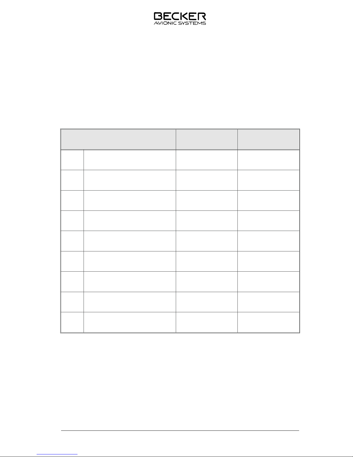
Sec ti on DV 64440.03 DV 64440.04
1 Ge ne ral In for ma ti on X X
2 In stal la ti on X X
3 Ope ra ti on X X
4 Theo ry of Ope ra ti on X
5 Main ten an ce and Re pair X
6 IIlu stra ted Parts List X
7 Mo di fi ca ti on and Chan ges X
8 Cir cuit Dia grams X
9 List of the used Ab bre via tions X
1.2 Ap pli ca ti on
The Au dio Con trol Unit is part of the Di gi tal Voi ce Com mu ni ca ti on Sys tem DVCS 6100 and pro vi ded for
in stal la ti on in an air craft. It ser ves for the con trol of REU6100 Remo te Elec tro nic Unit. Ma xi mum six
Au dio Con trol Units can be con nec ted to the Remo te Elec tro nic Unit. The Au dio Con trol Unit is iden ti cal
for each in stal la ti on lo ca ti on (ca bin, cock pit, etc.).
ACU6100
DV 64440.03/.04 Issue 1 Sept./2005 Page 1-1

1.3 Ge ne ral des crip ti on
1.3.1 Mechanical description
The Audio Con trol Unit is de sig ned for in stal la ti on in the ope ra tor con so le of air craft. The di men sions
cor re spond to the ARINC 601 stan dard for con trol units. In stal la ti on is by me ans of four DZUS fa ste ners.
The Au dio Con trol Unit con sists of the fol lo wing elec tri cal as sem blies re spec ti ve ly cir cuit bo ards :
q Il lu mi na ti on board
q Ro ta ry board
q 2 x Vo lu me board
q Pro ces sor board
q Con nec tor Board
1.3.2 Elec tri cal des crip ti on
1.3.2.1 Ge ne ral Functions
The Au dio Con trol Unit shall com pri se a ma xi mum of six con trol pa nels to pro vi de the fol lo wing
functions in de pen dent ly:
q Dri ving of up to 8 trans cei vers or 7 trans cei vers plus one pub lic ad dress (PA) am pli fier
q In di ca ti on of trans mis si on via sta tus lights
q Mo ni to ring of up to 8 trans cei vers with a ca pa bi li ty of in di vi du al vo lu me con trol
q Mo ni to ring of up to 8 re cei vers with a ca pa bi li ty of in di vi du al vo lu me con trol
q Mo ni to ring of up to 6 fi xed in puts
q Mo ni to ring of up to 10 in ter nal ly ge ne ra ted sig nal to nes. 8 to nes can be ac ti vat ed by
di scre te con trol li nes from ex ter nal (au ral alert to nes).
q Main vo lu me con trol
q Air craft in ter com mu ni ca ti on in eit her VOX or PTT-controlled mode
q 2 in ter com cir cuits to se pa ra te cock pit and ca bin com mu ni ca ti on
q Op ti cal call in di ca ti on for in ter com re quest plus acous ti cal call alert for com bi ning or
se pa ra ting the dif fe rent in ter com cir cuits as sig ned to the in di vi du al con trol unit
q Ca pa bi li ty for dri ving and con trol ling a cock pit or ca bin spea ker de pen ding on the
con trol unit
q Pro vi si on for in ter com am pli fier con nec ti on
q Cock pit voi ce re cor der con nec ti on ca pa bi li ties se pa ra ted for pi lot an co pi lot
ACU6100
Page 1-2 DV 64440.03/.04 Issue 1 Sept./2005

q P-BIT, I-BIT, C-BIT functio na li ty with op ti cal in di ca ti on of test sta tus/re sult
q Fall-back to Back-Up ope ra ti on upon fai lu re of po wer supp ly (ba ckup po wer supp ly
from air craft ne ces sa ry!); ma nu al ly Back-Up ope ra ti on in case or of de fec ti ve Au dio
Con trol Unit or part the re of
q Con fi gu ra ti on ca pa bi li ty for sys tem in te gra ti on or main ten an ce shops to con fi gu re
and adapt the sys tem to the in di vi du al air craft re qui re ments
The functio nal ins crip tions of key caps, ro ta ry switch, and in cre ment sen sor are fi nis hed in whi te trans lu cent cha rac ters. Il lu mi na ti on is com pa ti ble with com mon ly used night vi si on gog gles (NVG).
Every Au dio Con trol Unit has a mi cro con trol ler to pro cess switch and but ton ac ti vat ions as well as in di ca ti on sig nals. Con trol data is trans fer red via a dual re dun dant can bus in ter fa ce. SLA VE po si ti on (tog gle switch) and Back-up tog gle switch are not be rou ted through the in ter fa ce but must be hard-wi red
in or der to al low Back-up ope ra ti on, even if the unit had fai led.
Au dio Con trol Units are fac to ry con fi gu ra ble to dif fe rent ope ra ti on pro fi les, e.g. dis ab ling cer tain trans cei ver or re cei ver ac ces si bi li ty in the ca bin / pas sen ger area. Au dio Con trol Units may also be equip ped
with front pa nels im prin ted to cus to mer re quests.
All con trols and LED- in di ca tors of the Au dio Con trol Unit are lo ca ted on the ro ta ry board, pro ces sor
board and vo lu me boards :
Ro ta ry board:
The fol lo wing are moun ted on the ro ta ry board
q 1 ro ta ry switch, 10 po si tions, to pre se lect the ac ti ve trans cei ver as well as Pub lic Ad -
dress or In ter com mode. Also to se lect dual trans mis si on mode if pro vi ded (op ti on).
q 1 lockable switch.
q 1 PTT but ton ( tog gle switch).
Processor board:
The fol lo wing are moun ted on the processor board
q Dual po ten tio me ter to set the in di vi du al main vo lu me con trol (ou ter ro ta ry knob) and
to set the in di vi du al IC vo lu me con trol (in ner ro ta ry knob).
q VOX po ten tio me ter to set the in di vi du al VOX vo lu me le vel.
Vo lu me board (top)
The fol lo wing are moun ted on the vo lu me board (top).
8 moni to ring but tons to switch on /off trans cei ver monit oring and in du vi du al vo lu me con trol.
ACU6100
DV 64440.03/.04 Issue 1 Sept./2005 Page 1-3

Vo lu me board (bot tom)
The fol lo wing are moun ted on the vo lu me board (bot tom)
8 mo ni to ring but tons to switch on /off re cei ver mo no tring and in du vi du al vo lu me con trol.
Il lu mi na ti on board
The fol lo wing are moun ted on the íl lu mi na ti on board
q VOICE but ton with LED to switch on and off the ident fil ter (green LED: fil ter on, ident
fre quen cy 1020 Hz sup pres sed)
q TEST but ton with green LED to in itia te the I-BITE. By pres sing the test button an in -
ter nal self test pro ce du re is start ed. Af ter the test the fol lo wing re sults are shown:
Re sult ”GO” LED goes off
Re sult ”NOGO” LED flas hes for all con trol functions
q SPKR but ton with LED to switch on and off the cock pit spea ker (green LED: spea ker
on)
q ISOL /CALL with LED to con trol the in ter com functions bet ween cock pit and ca bin
Con nec tor board
The two unit con nec tors are fit ted on the con nec tor board.
ACU6100
Page 1-4 DV 64440.03/.04 Issue 1 Sept./2005
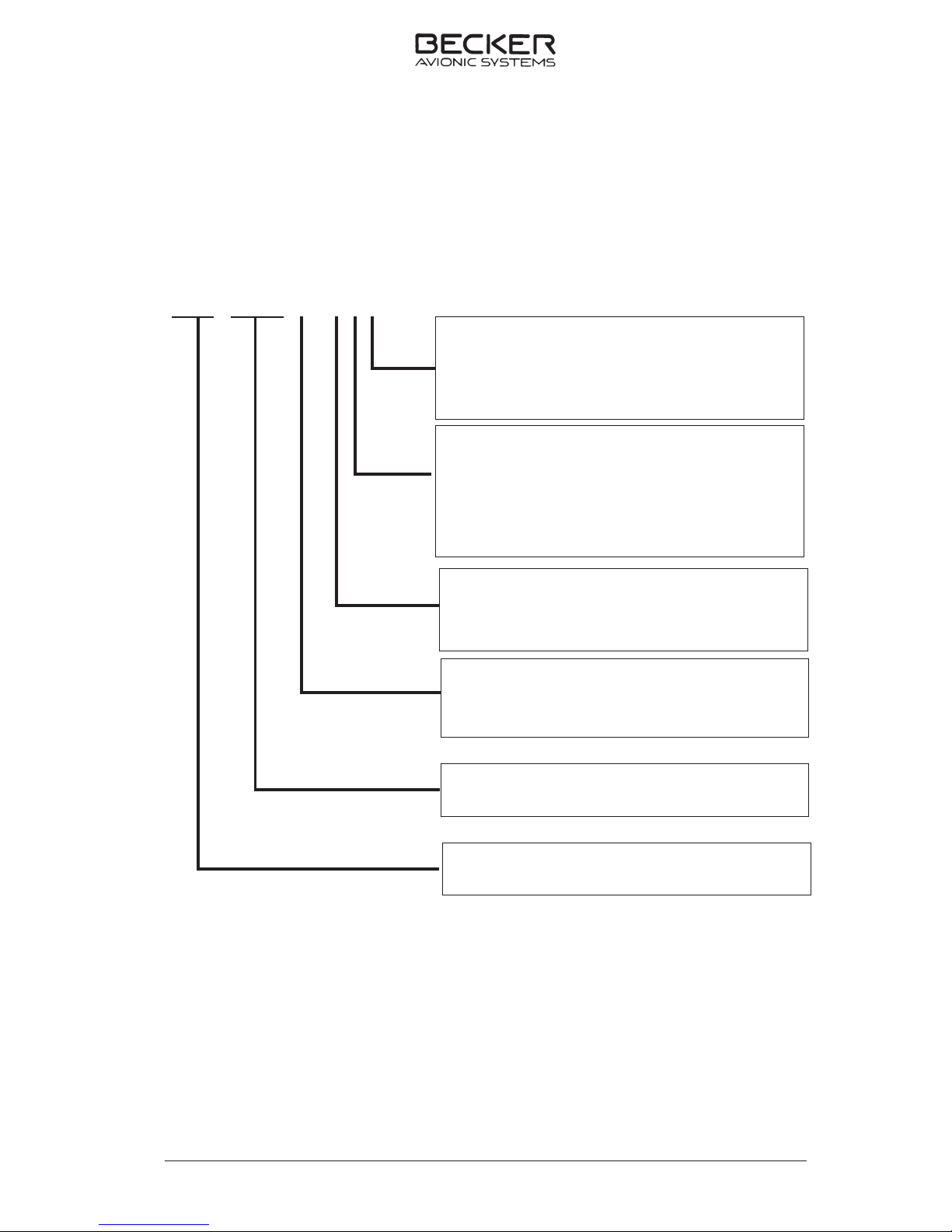
1.4 Identificationofarticle
1.4.1 TypesofAudioControlUnit
AudioControlUnit Part-numberACU6100-X-(XXX)
ACU6100-X-(XXX)
ACU6100
DV64440.03/.04Issue1change2Oct./2008 Page 1-5
Panelconfigurations
2 StandardPanelInlays
3 BlankPanelInlays
1 noNVGcompliant
2 NVGcompliant
Identificationnumber
AudioControlUnit
0= Panelcolor=black
1= Panelcolor=black(NVISfriendly)
2= Panelcolor=Grey
3= Panelcolor=Grey(NVIScompliant)
Illumination
0= Dimming=0.....28V(green)
1= Dimming=0.....5V(green)
2= Dimming=0.....28V(white)
3= Dimming=0.....5V(white)

1.5 Tech ni cal da ta
1.5.1 Po wer supp ly
Supp ly vol ta ge (Bus) I 27.5 V DC no mi nal
18.0 V DC emer gen cy
Supp ly vol ta ge (Bus) II 27.5 V DC nominal
18.0 V DC emergency
Back-Up vol ta ge (Bus) II 27.5 V DC no mi nal
18.0 V DC emer gen cy
Po wer con sump ti on ≤ 150 mA
Dim ming in put:
Dim con trol in put 1 max. 27.5 V DC
(pa nel il lu mi na ti on)
Dim con trol in put 2 max. 27.5 V DC
(LED bright ness)
1.5.2 Con trol data trans fer ACU-REU
In ter fa ce Dual CAN Bus (re du ndant)
Pro to col BFW specific
1.5.3 Me cha ni cal data
Width 145.8 mm
Heigth 75.8 mm
Depth 91.5 mm
Stan dard ARINC 601 8HE
Weight ≤ 800 g
Moun ting D-ZUS
ACU6100
Page 1-6 DV 64440.03/.04 Issue 1 Sept./2005

1.5.4 Unit con nec tors
Unit con nec tor P1 10-pol. series 851
Con trol bus- con nec tor P2 19-pol. series 851
- loc king de vi ce bayo net
1.5.5 En vi ron men tal con di tions
In put vol ta ge ran ge 22.0 to 30.3 V DC
- no mi nal in put vol ta ge 27.5 V DC
- emer gen cy in put vol ta ge 18.0 V DC
Ope ra ting tem pe ra tu re -40° C … +70° C
Sto ra ge tem pe ra tu re -55° C … +85° C
Al ti tu de max. 50.000 ft.
Hu mi di ty ra ting RTCA DO-160D, Cat. B,
Vi brat ion RTCA DO-160D, Cat. S,
vi brat ion cur ves M
RTCA DO-160D, Cat. U,
vibrat ion cur ves G
Ope ra ti onal shock 6 g in all directions
Crash sa fe ty 20 g shocks
20 g acceleration
Com pass safe dis tan ce mag ne tic effect no in flu en ce at a dis tan ce
of 30 cm, EU RO CAE /
RTCA ED-14D/DO-160D Class Z
1.6 Soft wa re
All data for ACU 6100 is sto red in the microcontroller. If the con trol ele ments are al te red, a data trans mis si on im me di ate ly ta kes pla ce to the Remo te Elec tro nic Unit. The soft wa re is clas sed as le vel C in
ac cor dan ce with the EU RO CAE / RTCA do cu ment ED12B / DO-178B.
ACU6100
DV 64440.03/.04 Issue 1 Sept./2005 Page 1-7
1.7 Appro vals
LBA-No.: TBD
ETSO ETSO - C50c Au dio Se lec tor
Pa nels and Am pli fiers
Soft wa re EU RO CAE/RTCA DO-178B/
ED-12B Le vel C
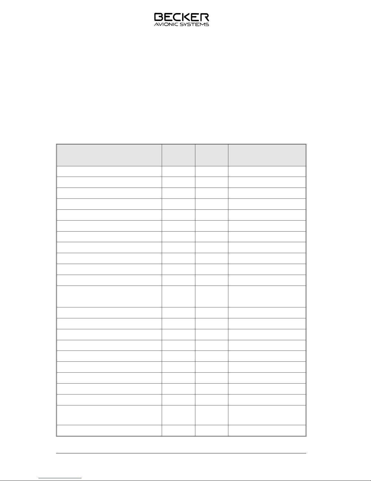
1.8 En vi ron men tal qua li fi ca ti on (EU RO CAE/RTCA ED-14D/DO-160D)
Cha rac te ris tic
ED-14D/DO-160D
Section Category Condition
Tem pe ra tu re / Altitude 4.0 D1
Low ground sur vi val temperature 4.5.1 D1 -55° C
Low ope ra ting tem pe rature 4.5.1 D1 -40° C
High ground sur vi val temperature 4.5.2 D1 +85° C
High short-time ope ra ting temperature 4.5.2 D1 +70° C
High ope ra ting temperature 4.5.3 D1 +55° C
In-Flight loss of cooling 4.5.4 Z no au xi lia ry coo ling required
Altitude 4.6.1 D1 50,000 ft.
Te mpe ra tu re variation 5.0 B 5° C per minute
Humidity 6.0 B 48 h at 65°C at 95% RH
Shock 7.0 B Test Type R in all 6 directions
Vibration 8.0 S
U
M
G
Ex plosi on proofness 9.0 X
Wa ter proofness 10.0 X
Fluids susceptibilities 11.0 X
Sand and dust 12.0 X
Fun gus resistance 13.0 X
Salt spray 14.0 X
Mag ne tic effect 15.0 Z less than 0.3 m
Po wer in put (DC) 16.0 B
Vol ta ge spike 17.0 A
Au dio fre quen cy con duc ted
susceptibility
18.0 A
In du ced sig nal sus cep ti bi li ty 19.0 A
ACU6100
Page 1-8 DV 64440.03/.04 Issue 1 Sept./2005
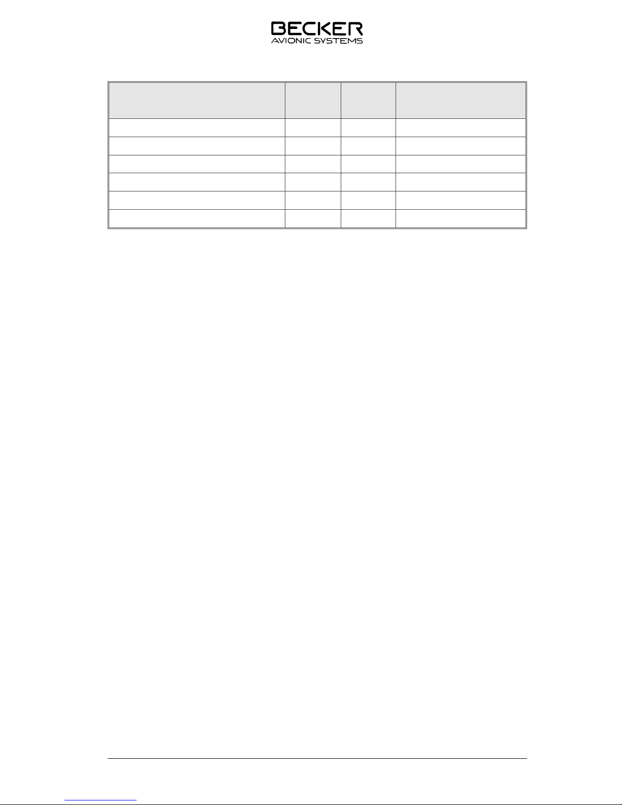
Cha rac te ris tic
ED-14D/DO-160D
Section Category Condition
Ra dio fre quen cy sus cep ti bi li ty 20.0 WR
Emis si on of RF 21.0 M
Light ning in du ced tran sient sus cep ti bi li ty 22.0 A3E3
Light ning di rect effects 23.0 X
Icing 24.0 X
Elec tro sta tic disch ar ge (ESD) 25.0 A
1.9 Sco pe of de li very
ACU6100-2-(120) Au dio Con trol Unit Ar ti cle-No.: 0585.319-921
ACU6100-2-(130) Au dio Con trol Unit Ar ti cle-No.: 0588.921-921
ACU6100-2-(230) Au dio Con trol Unit Ar ti cle-No.: 0597.678-921
1.10 Ac ces so ries (not con tai ned in the sco pe of de li vey)
Con nec tor Kit CK 5102-C Ar ti cle-No.: 0586.889-954
con sists of
10-pol. ca ble con nec tor, crimp Ar ti cle-No.: 0858.188-277
19-pol. ca ble con nec tor, crimp Ar ti cle-No.: 0794.279-277
CSW 6100 con fi gu ra ti on soft wa re set Ar ti cle-No.: 0589-047-919
con sists of
CAN - USB -Adap ter
CSW 6100 USB Don gle
In stal la ti on CD CSW 6100
Ma nu als:
In stal la ti on and Ope ra ti on DV 64440.03 Ar ti cle-No.: 0589.845.071
Main ten an ce and Re pair DV 64440.04 Ar ti cle-No.: 0589.853.071
In stal la ti on and Ope ra ti on Con fi gu ra ti on Ar ti cle-No.: 0590.428.071
Soft wa re CSW 6100 DV 6449.01
Ope ra ting instructions Ar ti cle No.: 0590.363-071
Blank
ACU6100
DV 64440.03/.04 Issue 1 Change 1 Jan./2008 Page 1-9

Blank
ACU6100
Page 1-10 DV 64440.03/.04 Issue 1 Sept./2005

TAB LE OF CON TENTS
Sec ti on 2 IN STAL LA TI ON Page
2.1 Ge ne ral 2-1
2.2 In spec ti on be fo re in stal la ti on 2-1
2.3 Me cha ni cal in stal la ti on 2-1
2.4 Air craft wi ring 2-1
2.4.1 Ge ne ral 2-1
2.4.2 Pa nel il lu mi na ti on 2-4
2.4.3 Con nec tor pin as signments 2-4
2.5 Con fi gu ra ti on soft wa re 2-6
Fig. 2-1 In stal la ti on di men sions Au dio Con trol Unit (mea su res in mm) 2-2
Fig. 2-2 Phy si cal lo ca tions of Au dio Con trol Unit con nec tors 2-3
Fig. 2-3 Lo gi cal pin as signment Au dio Con trol Unit 2-3
Fig. 2-4 Au dio Con trol Unit po wer con nec tions 2-5
Fig. 2-5 Au dio Con trol Unit con nec tions 2-5
Fig. 2-6 Bus in ter wi ring with 3 ACUs 2-7
Fig. 2-7 Au dio Con trol Unit bus con nec tions 2-9
ACU6100
DV 64440.03/.04 Is sue 1 Sept./2005 Page 2-I

BLANK
ACU6100
Page 2-II DV 64440.03/.04 Is sue 1 Sept./2005

Sec ti on 2 IN STAL LA TI ON
2.1 General
The in stal la ti on of the Au dio Con trol Unit de pends on the type of air craft and its equip ment and the re fo re only ge ne ral in for ma ti on can be gi ven in this sec ti on.
2.2 In spec ti on befo re installation
Be fo re in stal ling the Au dio Con trol Unit in an air craft, car ry out a vi su al in spec ti on for any trans port da ma ge, pay ing par ti cu lar at ten ti on to the fol lo wing:
- Dirt, dents, scrat ches, cor ro si on, bro ken at ta ching parts on the hou sing and hou sing parts.
- Dirt and scrat ches on the iden ti fi ca ti on pla te, front pa nel and marking.
- Dirt, bent or bro ken pins, cra cked con nec tor in serts.
- Dirt and me cha ni cal da ma ge on the ro ta ry swit ches, push-buttons and knobs.
- Mis sing screws.
2.3 Me cha ni cal installation
The Au dio Con trol Unit is de sig ned for in stal la ti on in the ope ra tor con so le of an air craft. The ne ces sa ry
di men sio nal de tails are gi ven in Fig. 2-1. The unit is at ta ched using four DZUS fa ste ners.
2.4 Air craft wiring
2.4.1 General
The Au dio Con trol Unit con nec tions can be seen in Fig. 2-4 to Fig. 2-7 . The fol lo wing points are to be
ob ser ved for the wi ring :
a. Only cable fit for avia ti on (self-extinguishing) may be used. AWG 20 for po wer supply and AWG 24
for ot her ca bles.
b. The in ter fa ce li nes are each to be laid as 2-core twis ted and scree ned (AWG 24) ca bles.
c. Every sing le ca ble harness of a unit con nec tor must get a se pa ra te scree ning.
d. Rub ber slee ves are to be fit ted over the sol de ring points on the unit con nec tor.
e. No HF ca ble should be in clu ded in the ca ble har nes ses. Lay ing con nec ting ca bles to get her with ca -
bles which cary AF po wer or im pul ses is also be avoi ded.
f. Check the wi ring care ful ly be fo re swit ching on the units, par ti cu lar ly that (UB+) and (GND) have not
been mi xed up.
ACU6100
DV 64440.03/.04 Issue 1 Sept./2005 Page 2-1

Fig. 2-1 In stal la ti on di men sions Au dio Con trol Unit (mea su res in mm)
ACU6100
Page 2-2 DV 64440.03/.04 Issue 1 Sept./2005

Fig. 2-2 Phy si cal lo ca tions of Au dio Con trol Unit con nec tors
Fig. 2-3 Lo gi cal pin as signment Au dio Con trol Unit
ACU6100
DV 64440.03/.04 Issue 1 Sept./2005 Page 2-3
P 1
Dim,
IC hotmike
hardwire d
safety related
Power
A
B
C
D
E
F
G
H
J
K
B-BuS
P 2
Gnd
Dev.Nr.
BB1
BB2
A
C
DR
E
B
PN
V
F
K
H
J
G
U
T
L
M
S
Reset in
Reset out
10 pol.19 pol.
B-BUS
P 2
P 1
CAN1
CAN2

2.4.2 Panel illumination
The Au dio Con trol Unit is fit ted with pa nel lighting. It can also be con nec ted via a dim mer sys tem.
Pa nel illumination con nec ti on Re mark
Plug P 1 - Pin E Dim Con trol in 1 (pa nel il lu mi na ti on)
Plug P 1 - Pin A Dim Con trol in 2 (bright ness of LEDs)
2.4.3 Connector pin assignments
P1 Type 851-02 E 12-10 P 50, shell 12, 10-pol., bayo net
Pin Con nec ti on Re mark
C DC1 +27.5 V
D GND1
G DC2 + 27.5 V
F GND2
H PTT
B Back-up
K Sla ved
J
Hot mike in
E Dim Con trol in 1 pa nel il lu mi na ti on
A Dim Con trol in 2 bright ness of LED’s
P2 Type 851-02 E 14-19 P 50, shell 14, 19-pol., bayonet
Pin Con nec ti on Re mark
L Dev Nr Bit 0
M Dev Nr Bit 1
A Dev Nr Bit 2
B Dev Nr Bit 3
U Re set out
V Re set in
N GND
C BB1-HI-in
D BB1-LO-in
P BB1-SH-in
ACU6100
Page 2-4 DV 64440.03/.04 Issue 1 Sept./2005

Pin Con nec ti on Re mark
E BB1-HI-out
F BB1-Lo-out
R BB1-SH-out
G BB2-HI-in
H BB2-Hi-out
S BB2-SH-in
J BB2-HI-out
K BB2-LO-out
T BB2-SH-out
Fig. 2-4 Au dio Con trol Unit po wer con nec tions
ACU6100
DV 64440.03/.04 Issue 1 Sept./2005 Page 2-5
DC 1 +27,5V C
DC 1 GND D
DC 2 +27,5V G
DC 2 GND F
PTT H
Back Up Switch Out B
Slave Switch Out K
IC Hot Mike In J
Dim Control 1 In E
Dim Control 2 In A
all P1
ACU6100

Fig. 2-5 Au dio Con trol Unit con nec tions
Note
The in ter wirng dia gramm for the Au dio Con trol Unit and Re mo te Elec tro nic Unit is lo ca ted in the
Ma nu al “In stal la ti on an Ope ra ti on” DV 64460.03.
2.5 Con fi gu ra ti on soft wa re
The fac to ry con fi gu ra ti on of the DVCS 6100 can be chan ged with aid of a Per so nal Com pu t er or Lap top and the soft wa re CSW 6100 (Ar ti cle-No. 0589.047-989).
Page 2-6 DV 64440.03/.04 Issue 1 Sept./2005
ACU 6100-X-(XXX)
Device Address Bit0 L
Device Address Bit1 M
Device Address Bit2 A
Device Address Bit3 B
Address Ground N
Reset out U
Reset in V
CAN1 in (HI) C
CAN1 in (LO) D
CAN1 in (shield) P
CAN1 out (HI) E
CAN1 out (LO) F
CAN1 out (shield) R
CAN2 in (HI) G
CAN2 in (LO) H
CAN2 in (shield) S
CAN2 out (HI) J
CAN2 out (LO) K
CAN2 out (shield) T
ACU6100
all P2

Fig. 2-6 Bus in ter wi ring with 3 ACUs
ACU6100
DV 64440.03/.04 Issue 1 Sept./2005 Page 2-7

Note
The ends of each bus must be ter mi na ted with 120 Ω. It can be in the har ness or on a se pa -
ra te juncti on block.
For cor rect ope ra ti on with one ACU re mo ved, a dum my ma ting con nec tor will have to be
con nec ted in it’s pla ce.
ACU6100
Page 2-8 DV 64440.03/.04 Issue 1 Sept./2005

B Bit 3
A Bit 2
MBit 1
L Bit 0
N Addr. GND
CBB1 In (Hi)
DBB1 In (Lo)
GBB2 In (Hi)
HBB2 In (Lo)
VReset In
U
Reset Out
(Hi) BB1 OutE
(Lo) BB1 OutF
(Hi) BB2 OutJ
(Lo) BB2 Out
K
B
Bit 3
A
Bit 2
M
Bit 1
L
Bit 0
N
Addr. GND
CBB1 In (Hi)
DBB1 In (Lo)
GBB2 In (Hi)
HBB2 In (Lo)
VReset In
U Reset Out
(Hi) BB1 Out
E
(Lo) BB1 Out
F
(Hi) BB2 OutJ
(Lo) BB2 Out
K
B Bit 3
A Bit 2
MBit 1
L Bit 0
N Addr. GND
CBB1 In (Hi)
D
BB1 In (Lo)
GBB2 In (Hi)
HBB2 In (Lo)
VReset In
U Reset Out
(Hi) BB1 OutE
(Lo) BB1 OutF
(Hi) BB2 OutJ
(Lo) BB2 Out
K
BBit 3
ABit 2
M
Bit 1
L
Bit 0
NAddr. GND
CBB1 In (Hi)
DBB1 In (Lo)
GBB2 In (Hi)
HBB2 In (Lo)
VReset In
U
Reset Out
(Hi) BB1 OutE
(Lo) BB1 OutF
(Hi) BB2 Out
J
(Lo) BB2 OutK
B Bit 3
A Bit 2
MBit 1
L Bit 0
N Addr. GND
CBB1 In (Hi)
DBB1 In (Lo)
GBB2 In (Hi)
HBB2 In (Lo)
VReset In
U
Reset Out
(Hi) BB1 Out
E
(Lo) BB1 OutF
(Hi) BB2 OutJ
(Lo) BB2 OutK
B
Bit 3
ABit 2
M
Bit 1
L
Bit 0
N
Addr. GND
CBB1 In (Hi)
D
BB1 In (Lo)
GBB2 In (Hi)
HBB2 In (Lo)
V
Reset In
U
Reset Out
(Hi) BB1 OutE
(Lo) BB1 Out
F
(Hi) BB2 OutJ
(Lo) BB2 OutK
120
120
B
Bit 3
A
Bit 2
M
Bit 1
L
Bit 0
N
Addr. GND
C BB1 In (Hi)
D
BB1 In (Lo)
G BB2 In (Hi)
H BB2 In (Lo)
V
Reset In
UReset Out
(Hi) BB1 Out
E
(Lo) BB1 Out
F
(Hi) BB2 Out
J
(Lo) BB2 Out
K
120
120
Co-Pilot ACU 1
P2
P5
Pilot ACU 2
Cabin ACU 3
Cabin ACU 4
Cabin ACU 5
Cabin ACU 6
Termination
Termination
P2
P2
P2
P2
P2
P2
P2
P2
P2
P2
P2
P2
P2
P2
P2
P2
P2
P5
P5
REU
Fig. 2-7 Audio Control Unit bus connections
Note 1: The ends of each Bus must be terminated with 120 Ohm. It can be in the harness or on a separate Junction Block.
Note 2: For correct operation with one ACU removed, a dummy mating connector will have to be connected in it’s place.
Note 3: The wiring shields can be connected to the connector backshells.
Page 2-9/2-10
DV 64440.03/.04 Issue 1 Sept./2005


TABLE OF CONTENTS
Section 3 OPERATION Page
3.1 Operating controls 3-1
3.2 Description and function of the operating controls and indicators 3-1
3.3 Operating instructions 3-3
3.3.1 Preparations (power-up test) 3-3
3.4 Transceiver operation 3-4
3.4.1 Transceiver monitoring 3-4
3.4.2 Individual transceiver channel volume adjustment 3-4
3.4.3 Monotoring TX- channel volume adjustment 3-4
3.4.4 Main volume adjustment 3-4
3.5 Selection of transmission mode 3-5
3.5.1 Selection a transceiver for transmission 3-5
3.5.2 Selection of dual transmission mode 3-5
3.5.3 Selection of intercom PTT 3-5
3.5.4 Forced monitoring 3-5
3.5.5 Transmission mode 3-6
3.5.6 Dual transmission mode 3-7
3.6 Receiver operation 3-8
3.6.1 Reciever monitoring 3-8
3.6.2 Individual receiver channel volume adjustment 3-8
3.6.3 Monitored RX-channel visualization 3-8
3.6.4 Main volume adjustment 3-9
3.6.5 Voice filter activation 3-9
3.6.6 Loudspeaker operation 3-9
3.7 Intercommunication 3-11
3.7.1 Virtual intercom circuits 3-11
3.7.2 Cockpit CALL/ISOL functionality 3-12
3.7.3 Cabin CALL/ISOL functionality 3-12
3.8 Intercom activation 3-12
3.8.1 Voice controlled intercom 3-13
3.8.2 VOX level adjustment 3-13
3.8.3 PTT controlled intercom 3-13
3.8.4 External switch controlled intercom 3-13
3.8.5 IC volume adjustment 3-14
3.8.6 Winch man intercom 3-14
3.8.6.1 Winch man VOX level functionality 3-14
3.8.6.2 Winch man volume level functionality 3-15
3.8.7 Emergency CALL function 3-15
3.8.8 Selective CALL function 3-15
3.8.9 Allocation of selective CALL 3-15
3.8.10 Selective CALL indication 3-15
3.8.11 Selective CALL forced monitoring 3-15
ACU6100
DV 64440.03/.04 Issue 1 Sept. / 2005 Page 3-I

3.9 Built IN Test 3-16
3.9.1 Power- up built in test (P-Bit) 3-16
3.9.2 Continuous built in test (C-Bit) 3-16
3.9.3 Initiated built in test (I-Bit) 3-16
3.10 Emergency operation 3-17
3.10.1 Slave operation 3-17
3.10.2 Back-up operation 3-17
3.10.3 Back-up switch activated 3-17
3.10.4 Automatic activation 3-18
Fig. 3-1 Front panel of the Audio Control Unit with generic button-description 3-1
ACU6100
Page 3-II DV 64440.03/.04 Issue 1 Sept. / 2005

Section 3 OPERATION
3.1 Operating controls
Fig. 3-1 Front panel of the Audio Control Unit with generic button-inscription
3.2 Description and function of the operating controls and indicators
Item Control / Indicator Description Function
A TX1 to TX8 controls 8 potentiometer with
push-push switches
On/Off switch for every TX channels and
individual volume adjust for audio monitoring
B TX indicators 1 to 8 8 LED’s (green) Indication of individual TX channel status
LED on = channel is preselected for
transmission
LED blinking = transmission is
activated
LED blinking = Selective “CALL” is activated
fast
C Transmitter selector
switch
Rotary switch with 10 lock
positions
Position 1 to 8 preselection of TX channel for
transmission
Position D selection of 2 predefined TX
channels for dual trans-
mission mode
Position IC Intercom PTT mode
DV 64440.03/.04 Issue 1 Sept./2005 Page 3-1
ACU6100

Item Control/Indicator Description Function
D ICvolumecontrol Potentiometer Volumeadjustmentforintercom
E “SPKR”indicator LED(green) LED on = Speaker is on
LED off = Speaker is off
F
“SPKR” button Push-button On/Offswitchforaudiomonitoringviathe
speaker
G “ISOL/CALL”indicator LED
(green)
LED on = cockpit and cabin intercom circuits
are isolated
LED off = cockpit and cabin intercom circuits
are connected
LED blinking = intercom request
“CALL” is active
H “ISOL/CALL”button Push-button Cockpit connect or truncate the cockpit and
cabin intercom circuits
Cabin initiates an intercom request “CALL” if
the intercom circuits are truncate
I Volume control Potentiome ter, Mainvolumecontrol
J RX1toRX8controls 8potentiometerwith
push-pushswitches
On/OffswitchforeveryRXchannelsandindi
-
vidualvolumeadjustforaudiomonitoring
K PTT switch Momentary switch with 2
key positions
Switch pressed = selected transmitter is
keyed
Switch released = selected channels are
monitored
L BACK-UP switch Toggleswitchwith3lock
positions
Position BACK-UP = emergency operation
Position NORM = normal operation
Position SLAVED = slave operation
M VOX level adjustment
VOX ON/OFF switch
Potentiometerwith
push-pushswitch
VOX sensitivity selection
ON/OFF switch for VOX activation
N “VOICE” button Push-button On/OffswitchforVOICEfilter
(forconfigured-RXchannels)
O “VOICE” indicator LED
(green)
LED on = voice filter is active
LED off = voice filter is not active
P “TEST” button Push-buton Activation of IBIT (test function)
Q “TEST” indicator LED
(yellow)
LED on = internal self test is running
LED blinking = the internal selftest detected
an failure
Page 3-2 DV 64440.03/.04 Issue 1 change 2 Oct./2008
ACU6100

3.3 Operating instructions
3.3.1 Preparations (power-up test)
1. Switch on the unit by using the audio selector master switch (circuit breaker).
2. When the Audio Control Unit is powered, the devicesis starts an internal self test procedure. All the
microprocessors and memories are tested as well as data transfer between Audio Control Units
and remote electronic unit.
While the test is running, the LEDabove the ”TEST”push button illuminates. Thetest needs about4
seconds.
After the test the following results are shown:
q
No failure detected yellow LED is off; the system is in normal mode
q
Failure detected yellow LED blinking
If the internal test routine detected an failure (yellow LED is blinking), the operator has2 possibilities:
q
By pressing the “TEST” button, the failure can be acknowledged. In case at a per
-
mant problem inside the system, it will be detected by the continous self test routine
and indicated again.
q
Switching into the slaved or emergency mode by using the “BACK-UP” switch.
DV 64440.03/.04 Issue 1 Sept./2005 Page 3-3
ACU6100

3.4 Transceiver operation
3.4.1 Transceiver monitoring
For transceiver monitoring, a TX-channel is activated by push release of the respective knob.
q
Knob released monitoring ON
q Knob impressed monitoring OFF
Several transceivers may be selected for monitoring at the same time.
3.4.2 Individual transceiver channel volume adjustment
The individual volume for the monitored channels can be selected by turning the respective knob.
3.4.3 Monitored TX-channel visualization
The activated TX-channel (released) knobs are illuminated.
By looking at the panel from an angle that’s unequal to the rectangular top view, it’s easy to detect the
activated and deactivated channels.
An arrow on top of each knob helps the user to pick the selected volume of the several channels quick
-
ly.
3.4.4 Main volume adjustment
Main volume can be adjusted at any time by turning just the VOL control. This action adjusts the sum
volume of all activated TX- and RX-channels and the fixed inputs 4 to 6.
Page 3-4 DV 64440.03/.04 Issue 1 Sept./2005
ACU6100

3.5 Selection of transmission mode
3.5.1 Selecting a radio for transmission
For transmission with an individual radio, the transceiver is pre-selected by means of the TX-selector
rotary switch in the centre of the Audio Control Unit. In the given example TX-channel 1 is pre-selected
for transmission. The green LED illuminates (TX channel 1).
3.5.2 Selection of dual transmission mode
Positions 9 of the TX-selector rotary switch labelled with ”D” is for dual transmission mode. By system
configuration at installation time, 2 out of the 8 TX-channels can be defined for usage in dual transmis
-
sion mode.
3.5.3 Selection of intercom PTT
The last position (by turning clock wise) of the TX-selector rotary switch selects the intercom to PTT
mode.
3.5.4 Forced monitoring
The reception signal of the radio which is pre-selected for transmission is monitored, even if it was not
active for monitoring before (forced monitoring).
Using the respective knob, the monitoring volume can be adjusted.
Forced monitoring can be deactivated during installation setup by configuration.
With activated ”Forced Monitoring”, in the following example, TX-channel 1 would be audible thus it is
not manually activated (knob not released).
DV 64440.03/.04 Issue 1 Sept./2005 Page 3-5
ACU6100

3.5.5 Transmission mode
By pressing a PTT switch (on panel or external), the following actions will result:
q
The selected transmitter will be keyed.
q
The green LED below the associated channel volume knob is flashing.
Note:
During transmission, all received signals possibly selected, are muted as well as signals
originating from aircraft intercommunication.
Only those warning tones which have been programmed as essential during installation
setup, are still audible when transmitting.
If loudspeakers are provided and if the one related to the individual control unit had been
switched on prior to transmitting, it will be muted to avoid acoustic feedback to the micro
-
phone.
Page 3-6 DV 64440.03/.04 Issue 1 Sept./2005
ACU6100

By speaking into the microphone while in transmission mode, the following actions will results:
q
The activated transmitter is modulated
q
A sidetone is audible with a volume that is in accordance with the preselection in the in
-
stallation setup. The individual volume for the monitored channels can be selected by
turning the respective knob.
q
The TX indications (blinking LED) assigned to an individual transmitter is active on all
ACUs when keyed by any operator.
q
Any transmitter could be modulated by different operators simultaneously.
By releasing the PTT switch (on panel or external), the following actions will results:
q
The transceiver turns back to receive mode
q
TThe green LED lights up (stops flashing)
q
All previously selected signals, intercom, and warning tones are resumed.
q
If the loudspeaker was activated before pressing PTT, it is switched on again.
3.5.6
Dual transmission
IIf the TX-selector rotary switch is turned to position ”D”, the operator activates 2 transceivers simultane
-
ously for dual transmission. The green LEDs (transceiver monitoring) from the selected transceivers illu
-
minate. The selection of the two transceivers for dual transmission is configured during installation setup
of the control unit.
By pressing a PTT switch (on panel or external), the transmission is indicated by the two corresponding
green LEDs flashing as long as the PTT switch is held.
The dual transmission mode can be blocked by system configuration.
DV 64440.03/.04 Issue 1 Sept./2005 Page 3-7
ACU6100

3.6 Receiver operation
3.6.1 Receiver monitoring
For receiver monitoring, a RX-channel is activated by push release of the respective knob:
q
Knob released ® monitoring ON
q
Knob impressed ® monitoring OFF
Several receivers may be selected for monitoring at the same time.
In the given example, RX-channel 1, 2 and 6 are selected for monitoring. RX-channel 5 is not audible,
even though the volume knob is not in the far left (ccw) position.
3.6.2 Individual receiver channel volume adjustment
The individual volume for the monitored channels can be selected by turning the respective knobs.
3.6.3 Monitored RX-channel visualization
The activated RX-channel (released) knobs are illuminates.
By looking at the panel from an angle that’s unequal to the rectangular top view, it’s easy to detect the
activated and deactivated channels.
An arrow on top of each knob helps the user to pick the selected volume of the several channels
quickly.
ACU6100
Page 3-8 DV 64440.03/.04 Issue 1 Sept./2005

3.6.3.1 Main volume adjustment
Main volume can be adjusted at any time by turning the VOL control. This action adjusts the sum volu
-
me of all activated TX- and RX-channels.
3.6.4 Voice filter activation
The system has the possibility to activate a 1020Hz notch filter for all the RX-channels. This is to sur
-
press identification codes in the incoming audio signals from navigation receivers (e.g. for listening to
weather information).
In the configuration of the system, the system integrator can define the RX-channels that will have this
filter.
Whilst operating, the filter can be activated and deactivated by pressing the ”VOICE” push button. The
status of voice filter activation is visible by a green LED in top of that push button:
q
“VOICE” LED on voice filter is active
q
“VOICE” LED off voice filter is not active
3.6.5 Loudspeaker operation
Note:
The DVCS6100 system provides two speaker channels which are assigned in the stan
-
dard version to ACU1 and ACU2.
Pressing the ”SPKR” button briefly, switches on the loudspeaker that is related to this
control unit. All selected TX/RX channel signals, intercom audio signals and warnings are
reproduced through the loudspeaker. The green LED above the button indicates the
speaker mode.
ACU6100
DV 64440.03/.04 Issue 1 Sept./2005 Page 3-9

Pressing the key once again, the speaker is switched off and the LED goes off.
When speaker mode is active with an individual Audio Control Unit, voice controlled intercommunicati
-
on (VOX) is disabled.
Intercom is still possible by activating the external IC button or by pressing the PTT button while the
TX-selector rotary switch is in position ”IC”. In both cases, the loudspeaker ismuted to avoid feedback.
ACU6100
Page 3-10 DV 64440.03/.04 Issue 1 Sept./2005

3.7 In ter com mu ni ca ti on
3.7.1 Vir tu al In ter com Cir cuits
The re are two in ter com cir cuits pro vi ded by the DVCS6100 Sys tem:
1. Cock pit crew
2. Ca bin crew
The in ter com in si de one of the se 2 cir cuits can not be in ter rup ted.
The in ter com bet ween cock pit and ca bin crew can be trun ka ted by pres sing the “ISOL/CALL” push but tom. When the in ter com mode bet ween cock pit and ca bin is in ter rup ted, than the green LED abo ve the
“ISOL/CALL” but tons il lu mi na te.
By using an ad di tio nal in ter com am pli fier (e.g. Be cker IC3100) pas sen gers can be con nec ted with the
in ter com sys tem. The se pas sen gers are re pre sen ting a third in ter com cir cuit which is con nec ted with
the ca bin in ter com cir cuit of the DVCS6100. It can be trun ca ted by an ex ter nal switch which is not
shown in the dia gram (see abo ve).
ACU6100
DV 64440.03/.04 Issue 1 Sept./2005 Page 3-11

3.7.2 Cockpit “ISOL/CALL” Functionality
In the cockpit, the ”ISOL/CALL” button is used to toggle the connection/disconnection between the
cockpit and the cabin intercom circuits.
A LED above this button indicates the actual status of the connection:
q
LED on ® cockpit and cabin intercom circuits are isolated
q
LED off ® cockpit and cabin intercom circuits are connected
3.7.3 Cabin “ISOL/CALL” Functionality
The “ISOL/CALL” buttonon the cabin ACUs gives the cabin passengers the possibility to call for a con
-
nection. The cockpit crew can react to this call by ending the isolation mode.
The LED above the “ISOL/CALL” button shows the call status in the following way:
q
LED off Cockpit and cabin intercom circuits are connected
q
LED blinking The ”CALL” button was pressed and the system is in call
mode. By pressing the “ISOL/CALL” key at his Audio
Control Unit the pilot or copilot can reestablish the
connection between the passengers. While the LED
indications are blinking, a CALL tone is audible in the
cockpit.The “CALL” tone can be enabled/disabled by
configuration.
q LED on The intercom system is in isolation mode
If the system is in call mode (blinking LED), there are two possibilities:
- the cockpit crew leave the isolation mode and connect the
intercom circuits (LED off).
- the cabin crew presses the ”CALL” button once again and
the system stays in isolation mode (LED on).
If the intercom circuits are connected (no isolation mode), the “ISOL/CALL” button on the cabin ACUs
have no function.
3.8 Intercom activation
Intercommunication between the different users can be activated in three ways:
q
Voice controlled
q
PTT controlled
q
External Switch controlled
ACU6100
Page 3-12 DV 64440.03/.04 Issue 1 Sept./2005

3.8.1 Voice Controlled Intercom
Inpositions”1”to”8”and”D”ofthe TX selector rotary switch, VoiceControlledIntercom(VOX)isestab
-
lished without the need for any further action (assuming no transmitter is keyed).
VoiceControlledIntercomcanbe activated or deactivated by switching functionality of theVOXknob.
q
VOX knob released Voice Controlled Intercom ON
q
VOX knob impressed Voice Controlled Intercom OFF
TheswitchfunctionoftheVOXknobcanbeactivatedordeactivatedby the Configuration Software.
3.8.2 VOX level adjustment
TheVOX level of the microphonesassociated with each ACU can be adjustedindependently for each
ACU by turning the VOX potentiometer knob. The VOX potentiometer knob can be impressed in the
same way as the channel volume knobs but without any switch functionality.
3.8.3
PTT controlled intercom
Setting the TX selector to position IC,enables intercom byusing the PTT button. Inthis case, themike
signal is forwarded to the intercom amplifier when the PTT switch is pressed only.
3.8.4 External switch controlled intercom
EachACU supports anexternal momentary or2-state switch foractivation ofa ”Hot MikeMode”. If this
switchisactivated,themikelineis”open”andthesignalisforwarded directly to the intercom amplifier.
ACU6100
DV 64440.03/.04 Issue 1 change 2 Oct./2008 Page 3-13

3.8.5 IC volume adjustment
For individual intercom volume adjustment, the ACU provides a dedicated potentiometer on the front
panel. The intercom volume is independent from the main volume.
The transmission mode always has a higherpriority than the intercom-munication mode. Ifan operator
activates the transmission mode for any transceiver, the ACU stops its ”VOX” or ”HOT MIKE” mode
and carries out transmission mode. Other ACUs are not affected and their operators may continue in-
tercommunication.
3.8.6 Winchman intercom
By pressing the special external push button the winchman function is activated.
With this, the winchman is able to increase the VOX level and the main volume for his headset. The ex
-
ternal push buttons (connected via discrete input lines) are mounted separatly from the corresponding
ACU in the winchman working area (near the cabin door).
By configuration, it is possible to assign the winchman functionality to any ACU.
The following sub paragraphs describe the winchman external buttons functionality in detail.
3.8.6.1 Winchman VOX level functionality
If the VOX level push button is pressed for a short time (0.3s to £ 3s), the VOX level is increased by one
step, until the maximum value is reached. If the VOX level push-button is pressed for a time ³3s, the
VOX level will be reset to the value selected on the correspondingACU panel. The VOX level can bere
-
set too, when the wichmann funtionis switched offand the volumecontrol or VOXcontrol on theACU is
changed.
ACU6100
Page 3-14 DV 64440.03/.04 Issue 1 Sept./2005

3.8.6.2 Winchman volume level functionality
If the winchman volume pushbutton ispressed ashort time(0.3s to£ 2s), the volume level is increased
by one step, until the maximum value is reached. If the winchman volume push button is pressed for a
time ³ 3s, the volume level will be reset to the value selected on the corresponding ACU panel. The
VOX level can be reset also, when the main volume control or VOX control on the related ACU is chan
-
ged.
3.8.7 Emergency CALL function
The Audio Control Unit provides an “Emergency CALL” (E-CALL) via a dedicated discrete input. If this
discrete input is activated, the “E-CALL” tone is audible for cockpit ACU operators. The “E-CALL” tone
is different from the intercom request CALL- tone.
The “E-CALL” functionality can be deactivated via system configuration.
3.8.8 Selective CALL function
A “Selective CALL” functionality is provided by the Audio Control Unit in a configurable way.
The system detects selective call status via a discrete input line.
The behaviour of the Audio Control Unit selective CALL functionality can be selected by configuration
of the system.
3.8.9 Allocation of “Selective CALL”
The “Selective CALL” function can be allocated to one of the 8 TX-channels white system integration
setup.
3.8.10
Selective CALL indication
As long as the “Selective CALL” discrete input is activated, the LED below the associated TX-channel
will blink with double frequency. The operator can react to this indication by activating the correspon
-
ding channel for monitoring (if not yet done) or starting communication.
3.8.11
Selective CALL forced monitoring
If forced monitoring for “Selective CALL” is activated in the configuration of the system, the associated
TX-channel is automatically monitored as long as the selective CALL is active.
If this channel is being already monitored, there is no additional action.
ACU6100
DV 64440.03/.04 Issue 1 Sept./2005 Page 3-15

3.9 Built in test
3.9.1 Power-up built in test (P-BIT)
Every time the system is powered, an internal self test procedure is started.
While the test is running, the LED above the ”TEST” push button illuminates. The test lasts up to 4 se
-
conds. After the test, the following results are shown:
q
No failure detected yellow LED is off; the system is in normal mode
q
Failure detected yellow LED blinking
If the internal test routine detected an failure (yellow LED is blinking), the operator has2 possibilities:
q
By pressing the “TEST” button, the failure can be acknowledged. In case ata perma-
nent problem inside the system, it will be detected by the continous selftest routine
and indicated again.
q
Switching into the slaved or emergency mode by using the “BACK-UP” switch
3.9.2 Continuous built in test (C-BIT)
During normal operation of the system, apermanent background test routineis continuously running.If
an error is detected, the ”TEST” LED starts to flash. If it is not a fatal error, the operator can acknowled
-
ge the failure by pressing the test button.
In case of notable degradationin unitor systemperformance, theoperator can turn to emergency ope
-
ration, either in ”SLAVED” or ”BACK-UP” mode.
3.9.3 Initiated built in test (I-BIT)
An initiated built in test can be activated on each ACU at any time by pressing the ”TEST” button (ex
-
cept during transmission mode).
ACU6100
Page 3-16 DV 64440.03/.04 Issue 1 Sept./2005

3.10 Emergency operation
3.10.1 Slave operation
Copilot ACU Pilot ACU
When switching the emergency toggle switch to position ”SLAVED” on ACU 1 or ACU 2, the matching
headset is disconnected from it’s audio processing circuits in the Remote Electronic Unit and it’s mike
and phone capsules are directly paralleled to the headset of the remaining ACU.
No further action is possible on the slaved Audio Control Unit.
”SLAVED” mode is a first step of security in the case where one of the control panels appears to be de
-
fective or not working.
3.10.2 Back-Up operation
The Audio Control Unit provides a back-up mode. This mode can be activated either by a dedicated
switch on the cockpit ACU panels or in an automatic way by the system itself.
3.10.3 Back-Up switch activated
The pilot or copilot have the possibility to activate the back-up mode by switching a special toggle
switch (after unlocking by pulling its lever) in position ”BACK UP”.
In this mode, the microphone and headphone amplifier is powered via an external emergency supply
provided by the aircraft.
The following signal routings and functionalities are active in back-up mode:
q
Headphone 1 - TX 1 & FIX 1
q
Headphone 2 - TX 2 & FIX 2
ACU6100
DV 64440.03/.04 Issue 1 Sept./2005 Page 3-17

q
Intercom volume level is fixed to 50%
q
No actions on the ACUs are supported
3.10.4 Automatic activation
When the two main power supply busses fail or if a fatal defect occurs within the unit’s internal supply,
the security logic falls back to Back-Up operation even if the ”BACK-UP” switchhad not been activated.
The signal routings and functionalities are as described in chapter 3.10.3
ACU6100
Page 3-18 DV 64440.03/.04 Issue 1 Sept./2005
 Loading...