

Page 1

1. Contents
2. Symbols used in the Installation Guide . . . . . . . . . . . . . . . . . . . . . . . . . . . . . . . . . . . . . . . . . 32
3. Safety and Installation Instructions . . . . . . . . . . . . . . . . . . . . . . . . . . . . . . . . . . . . . . . . . . . .32
4. Connection schematic for the OnlinePro . . . . . . . . . . . . . . . . . . . . . . . . . . . . . . . . . . . . . . . . 33
5. Installation of the GPS/GSM antenna . . . . . . . . . . . . . . . . . . . . . . . . . . . . . . . . . . . . . . . . . .34
6. Installation of the hands-free microphone . . . . . . . . . . . . . . . . . . . . . . . . . . . . . . . . . . . . . . . 38
7. Installation of the GSM/GPS Box . . . . . . . . . . . . . . . . . . . . . . . . . . . . . . . . . . . . . . . . . . . . . 40
8. Connection of the reverse signal . . . . . . . . . . . . . . . . . . . . . . . . . . . . . . . . . . . . . . . . . . . . . .43
9. Connection of the speed signal (GAL) from the speedometer/ tachometer . . . . . . . . . . . . . . 43
10. Installation/ Removal of the OnlinePro . . . . . . . . . . . . . . . . . . . . . . . . . . . . . . . . . . . . . . . . . 48
11. Initial operation. . . . . . . . . . . . . . . . . . . . . . . . . . . . . . . . . . . . . . . . . . . . . . . . . . . . . . . . . . . . 49
12. Calibration . . . . . . . . . . . . . . . . . . . . . . . . . . . . . . . . . . . . . . . . . . . . . . . . . . . . . . . . . . . . . . . 50
13. Service Mode . . . . . . . . . . . . . . . . . . . . . . . . . . . . . . . . . . . . . . . . . . . . . . . . . . . . . . . . . . . . . 52
14. Connections . . . . . . . . . . . . . . . . . . . . . . . . . . . . . . . . . . . . . . . . . . . . . . . . . . . . . . . . . . . . . . 57
15. Troubleshooting . . . . . . . . . . . . . . . . . . . . . . . . . . . . . . . . . . . . . . . . . . . . . . . . . . . . . . . . . . . 58
Installation Guide
Subject to errors and technical changes 31 Copyright by Becker GmbH, D-76303 Karlsbad
Page 2
Installation Guide
2. Symbols used in the Installation Guide
G denotes instructions which are important for your safety and the safety of others.
denotes instructions which are important for the installation and function of the unit.
3. Safety and Installation Instructions
The OnlinePro should only be installed by trained personnel.
• Disconnect the vehicle battery before installation of the unit.
G Note the safety instructions of the vehicle manufacturer (airbags, immobilisers etc.).
• Ensure that leads are installed in such a manner that they cannot be pinched, bent or pulled out.
• Before installation, park the vehicle in a safe and level place and remove the ignition key.
• If using branch connections, it is important to note the relevant cable section.
Subject to errors or technical changes 32 Copyright by Becker GmbH, D-76303 Karlsbad
Page 3
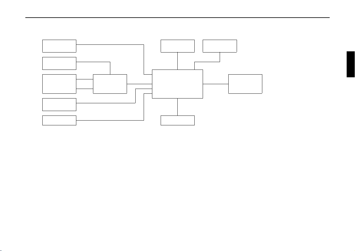
4. Connection schematic for the OnlinePro
Installation Guide
Speed signal
Earphone
Optional
GSM
Antenna
GPS
Hands-free
microphone
Reverse signal Power supply
GPS/GSM Box
antenna
Radio
OnlinePro
Note: Connection options are described in detail on page 57.
CD changer
Optional
Sound system /
loudspeaker
Subject to errors and technical changes 33 Copyright by Becker GmbH, D-76303 Karlsbad
Page 4
Installation Guide
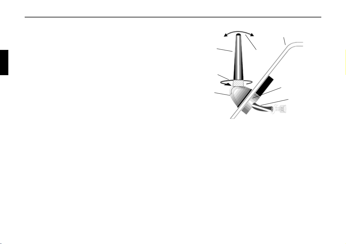
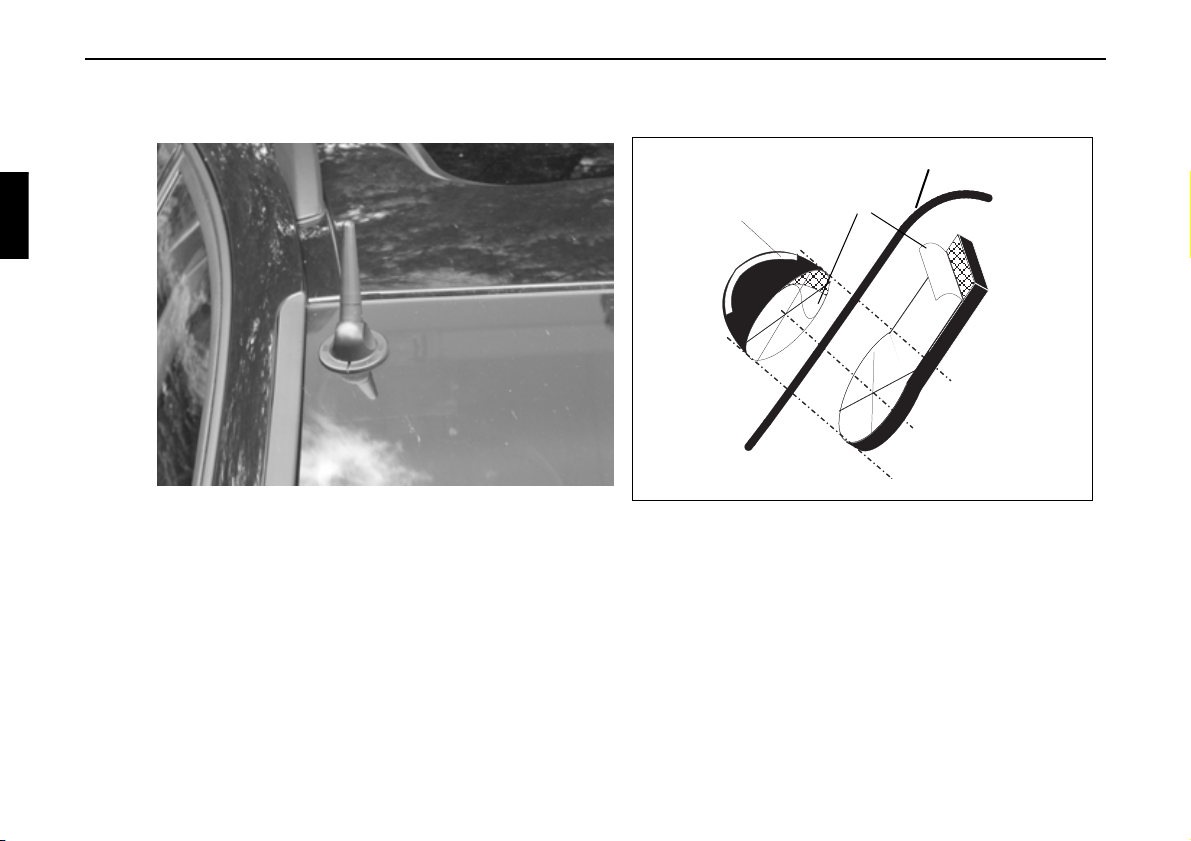
5. Installation of the GPS/GSM antenna
The antenna delivered with the system is a two-piece combination
GSM/GPS antenna. The combination GSM/GPS antenna is a glassadhesive antenna; i.e. no leads must be run from the outside to the
vehicle interior.
Windscreen or rear window
D
E
The GSM/GPS combination antenna consists of an internal unit A and
an external unit B. To ensure correct function, the two units must be
installed as described below: Attached to the internal unit A is a 3-metre
long cable C with the combined GSM/GPS plugs. The connecting cable
is connected to the GSM/GPS Box with the GSM/GPS plugs. If more
than 3 metres of cable are required, the cable can be extended with the
optionally available extension cable (Stock No. 1380311). The antenna
D can be loosened F to adjust the angle E by twisting the antenna. After
loosening and adjusting, the antenna D must be screwed on hand-tight.
The angle of the antenna to the vehicle has an influence on
)
the antenna’s transmission and reception.
If reception is still unsatisfactory after installation, the
angle of the antenna to the vehicle can be adjusted to
optimise reception. In most cases, best results are achieved
with the antenna in a vertical position.
Subject to errors or technical changes 34 Copyright by Becker GmbH, D-76303 Karlsbad
F
A
B
C
Page 5
Installation Guide
Installation of the GSM/GPS Antenna
G The antenna is to be affixed in such a manner that it cannot detach in the event of a collision or sudden
braking.
The antenna can only be installed under a non-metallised windscreen or rear window.
)
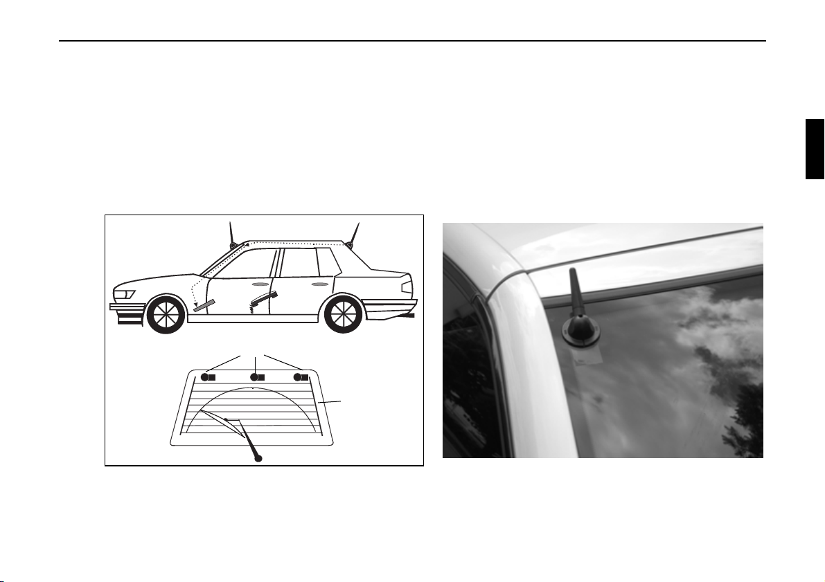
The installation of the GSM/GPS antenna on sharply angled windows (i.e. side windows or rear window in
estate cars/ stations wagons) is not recommended as satisfactory GPS reception cannot be ensured.
(1)
Possible antenna positioning
Rear window
Subject to errors and technical changes 35 Copyright by Becker GmbH, D-76303 Karlsbad
Page 6
Installation Guide
a. Determine installation position (1) (rear window, windscreen)
(2)
Slot faces upwards.
(A)
The antenna must not be affixed over the heating wires of heated windscreens or rear windows.
)
Windows with metal layered plastic window tinting are not suitable.
Take the windscreen-wiper range into account when positioning the antenna.
The glass surface to which the antenna must adhere, may be slightly curved.
When selecting position for installation, please bear in mind the possibility of cable extension.
Windscreen/Rear window
Protective paper
(B)
Subject to errors or technical changes 36 Copyright by Becker GmbH, D-76303 Karlsbad
Page 7

Installation Guide
G The driver’s field of vision must not be obstructed.
G Clean adhesion surfaces (inside and outside) with the enclosed cleaning cloth.
After cleaning, wait until the cleaned surfaces have dried.
b. Completely pull off protective paper from the adhesive surface (the square piece as well) (2). Caution: The
adhesive part is now exposed.
First adhere the external unit (A) with the slot at the top to the glass by firmly pressing (approx. 3-5 seconds)
around the circumference of the external unit base.
Subsequently, affix internal unit (B) to the inside of the window, once again by pressing on the housing of the unit
for approx. 3-5 seconds, with the circular area centred in the middle of the outside unit (centre point = centring
axis).
Depending upon the amount of space, the position of the internal unit can be turned on this centring axis before
being directly affixed.
The ideal adhesion temperature is between +15 °C and +25 °C.
)
The adhesive foil will adhere immediately to the adhesion surface and cannot be repositioned. It is not possible
to reuse the adhesive foil.
c. Run connecting cable to the installation position of the GSM/GPS Box.
Subject to errors and technical changes 37 Copyright by Becker GmbH, D-76303 Karlsbad
Page 8
Installation Guide
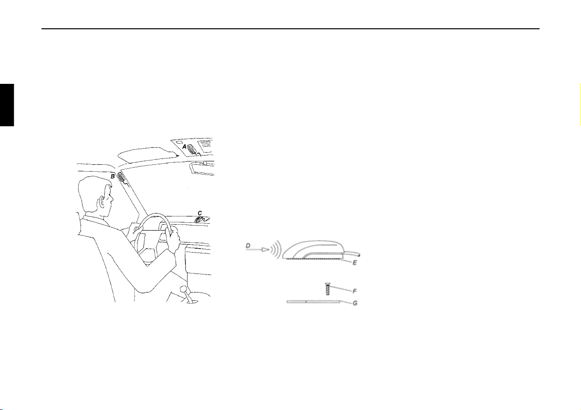
6. Installation of the hands-free microphone
The hands-free microphone should be placed in the vehicle to allow optimal recognition of the speaker’s voice. Possible
positions in the vehicle for the microphone can be seen in the following diagram.
The installation position should be as far away from the loudspeakers as possible. If problems occur, different
)
positions should be tested. In order to pick up as little background noise as possible, the microphone has a
narrow pick-up angle and must consequently be directed towards the driver.
A: Optimal installation position
B: Alternative installation position
C: Less suitable installation position
D: Speaking direction on microphone
E: Adhesive strip for affixing to smooth surfaces
F: Screw for fastening the screw-on plate
G: Screw-on plate for affixing to rough or uneven surfaces.
Affixing the hands-free microphone to a flat and smooth surface can be accomplished with the adhesive strip E (Clean
adhesion surfaces). If the microphone is to be affixed to a rough or uneven surface, the screw-on plate G should be affixed
first with the screw F (To avoid risk of damage, please pay attention to screw length). Subsequently, affix the microphone
to the screw-on plate G with the adhesive strip E. The connection of the hands-free microphones takes place in socket C
of the OnlinePro.
Subject to errors or technical changes 38 Copyright by Becker GmbH, D-76303 Karlsbad
Page 9
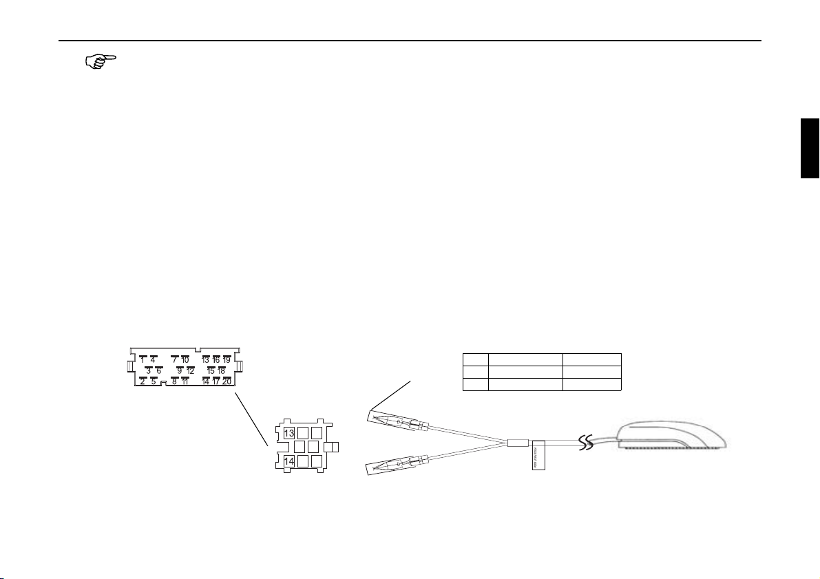
Install the lead in such a manner that it cannot be pinched, bent or pulled out.
Connection of the hands-free microphone to the OnlinePro
a. Connection without CD changer
For connection of the hands-free microphone to an OnlinePro without CD changer, the enclosed blue socket must
be connected as described below. Before connection, remove protective cap A from both contacts.
b. Connection with CD changer
For connection of the hands-free microphone to an OnlinePro with CD changer, the enclosed blue socket must
be connected with the two leads as described below. Before connection, remove protective cap A from both
contacts.
Once the contacts are inserted into the blue plug housing, a special tool is required to remove them.
)
Connection of the blue plug housing
Socket C
Pin Colour Function
A
Socket C3
13 White NF
14 Yellow Earth
Installation Guide
13
14
Subject to errors and technical changes 39 Copyright by Becker GmbH, D-76303 Karlsbad
Page 10

Installation Guide
7. Installation of the GSM/GPS Box
The connectors for the combination GSM/GPS antenna, the optional operating headset and connecting cable to the
OnlinePro are to be connected to the GSM/GPS Box. The SIM card necessary for activation and operation of the telephone
must be inserted into the card-holding slot.
A: Retaining cover over SIM card holder
A
B
F
C
D
E
B: Connection socket for connection
cable to OnlinePro
C: Connection for optional
F
operating headset
D: GPS antenna connection
E: GSM antenna connection
F: Velcro strip for attachment
Side view,
left
The GSM/GPS Box can be installed in the glove compartment, for example. However, an installation position allowing a
maximum possible distance from the Online Pro should be selected.
On the housing of the GSM/GPS Box, there are two Velcro strips F for attachment.
Install the lead in such a manner that it cannot be pinched, bent or pulled out.
The GSM/GPS Box should be installed in such a way that the SIM card inserted into the SIM card holder can be taken out
without having to remove the GSM/GPS Box.
Subject to errors or technical changes 40 Copyright by Becker GmbH, D-76303 Karlsbad
GSM/GPS Box
Side view,
right
Page 11

Inserting the SIM card
In order to insert the SIM card received from your network operator/
provider, the retaining cover A must be opened. If the SIM card was
delivered in "credit card" format, please detach the small section of the
card.
The SIM card holder is found under the retaining cover A.
Push the top side of the SIM card holder in the direction of the arrow.
Now lift up on the released SIM card insertion slot.
Slide the SIM card with the connectors into the raised SIM card
insertion slot. The slanted corner of the SIM card must face toward the
edge of the housing.
Subsequently, press the SIM card insertion slot back down and push in
the opposite direction of the arrow.
Close the retaining cover A.
Older SIM cards (5 Volt technology) cannot be used.
)
Please consult your network provider.
Installation Guide
Position of the SIM
card in the holder
A
GSM/GPS Box
Subject to errors and technical changes 41 Copyright by Becker GmbH, D-76303 Karlsbad
Page 12

Installation Guide
Connecting the leads
• Insert the connecting cable into socket B of the GSM/GPS Box and connect the other end of the cable to the
appropriate connection on the OnlinePro.
• Connect the additional earth lead to the lug intended for this purpose on the Online Pro
• Connect the GSM/GPS antenna plugs to the sockets D and E on the GSM/GPS Box.
• Connect the optional telephone handset (if available) to socket C of the GSM/GPS Box.
Additional earth lead
Subject to errors or technical changes 42 Copyright by Becker GmbH, D-76303 Karlsbad
Page 13

8. Connection of the reverse signal
If the switch on the gearbox or shift linkage is accessible:
• Connect a separate lead to the activated contact.
Connect lead to socket A, pin 2.
Low - level = earth, high - level 12 V - 16 V
If the switch is not accessible:
• Check which lead is routed to the reversing lamp. Then, if
necessary, remove the inner cover for the reversing light.
Connect a separate lead to the active lead of the reversing lamp and
connect with socket A, pin 2.
9. Connection of the speed signal (GAL) from the speedometer/ tachometer
Electronic speedometer
• Remove the signal from the speedometer, extend and connect to
socket A pin 1.
Installation Guide
A
Reverse
signal
Depending on the vehicle equipment, the lead for the GAL
)
signal is usually connected to the DIN - ISO plug of the car
radio. The assignment of the DIN - ISO plug may vary
depending on the vehicle type.
• Minimum requirement for the signal:
0.5 Hz - 4 kHz / Square wave signal
Low level < 0.3 V, High level 5 V - 16 V
If you do not know the exact installation position / location
)
of the speed signal, please consult the vehicle
manufacturer.
Subject to errors and technical changes 43 Copyright by Becker GmbH, D-76303 Karlsbad
GAL signal
A
Page 14

Installation Guide
Mechanical speedometer with built-in speed sensor in the speedometer cable
• Remove the signal from the speed sensor, extend and connect to
socket A pin 1.
• Minimum requirement for the signal:
0.5 Hz - 4 kHz / square wave signal
Low level < 0.3 V, High level 5 V - 16 V
If you do not know the exact installation position / location
)
of the speed signal, please consult the vehicle
manufacturer.
Mechanical speedometer without speed sensor in the speedometer cable
A speed sensor must be built into the speedometer cable to generate a
digital signal.
The VDO Adapter 2152.30300000 or a vehicle-specific adapter that
fulfils the minimum requirements can be used. The VDO speed sensor
is suitable for direct installation on the gearbox (no further installation
parts required) or in the speedometer cable (in conjunction with
additional universal installation parts).
If the sealed speedometer cable is released, a correct
)
display cannot be guaranteed. Incorrect installation leads to
improper functioning of the navigation system or of the
speedometer.
GAL signal
A
Subject to errors or technical changes 44 Copyright by Becker GmbH, D-76303 Karlsbad
Page 15

Installing the speed sensor directly on the gearbox
• Release the speedometer cable and screw speed sensor onto
gearbox. Screw released speedometer cable onto the speed sensor
and connect the wires.
Cable connections for the speed sensor
Brown - earth (terminal 31)
Black - power supply (terminal 15), 9 - 16V, 30 mA
Blue/red - signal for socket A pin 1
Installing the speed sensor in the speedometer cable
In order to install the speed sensor, the speedometer drive cable must
be cut at a straight section, in which the speed sensor is then inserted.
When removing the speedometer cable from the vehicle, ensure that the
location of the straight-routed section is determined and marked
accordingly.
Installation is illustrated without reference to any specific vehicle. In
addition to the sensor, the following VDO universal parts are required:
1 x connecting piece 1040 1300 025 (VDO part number)
2 x knurled nuts 1040 1000 003 (VDO part number)
2 x hose sleeves 1040 1000 031 (VDO part number)
2 x dogs 1040 1000 049 (VDO part number)
2 x friction washers 1040 0900 003 (VDO part number)
2 x fuel washers 4.0 KN07.0570.18 (VDO part number)
2 x washers KN11.1904.122 (VDO part number)
A complete set can also be ordered from VDO (Part number
X 39397106191).
Installation Guide
GAL signal
A
Figure 1
Subject to errors and technical changes 45 Copyright by Becker GmbH, D-76303 Karlsbad
Page 16

Installation Guide
Recommended tools: Cable installation tool for speedometer cables
from VDO, Order No: 1999.10.13.000.110
If you require vehicle-specific parts, please consult the vehicle
manufacturer or your nearest VDO branch.
• Using a metal saw, cut into the cable approx. 1 mm at a right angle
to the profile and break off (Figure 3).
• Then cut the cable in the centre with side-cutting pliers
(Figure 4).
For protective hoses with wire netting, the hose and flex
)
cable can be cut directly with the side-cutting pliers.
• Shorten the protective hose again at both ends up to the plastic
sheathing. Check whether the ends of the flex cable still engage in
the speedometer and the gearbox.
• Shorten the inner cable to a projection of 13 mm (Figure 5).
• Connect the union nut and hose sleeve (Figure 6) and push onto the
hose ends (Figure 7).
• Connect friction washer to dog (Figure 8).
Figure 3
Figure 4
Figure 5
Figure 6
Figure 7
Figure 8Figure 8
Subject to errors or technical changes 46 Copyright by Becker GmbH, D-76303 Karlsbad
Page 17

• Remove grease from flex cable and connect dog to flex cable.
Using a suitable installation tool, press the dog onto the flex cable
(Figure 9).
Installation Guide
When pressing in, ensure that the dog is securely positioned
)
and that it runs smoothly.
• Pull the hose sleeve and nut as far as possible in the direction of the
dog, to achieve approx. 1-2 mm play (Figure 10).
Slightly squeeze the hose sleeve with pliers. Wrap with isolating
tape to secure (Figure 11).
• Screw the connecting piece and the speed sensor into the cable
(Figure 12).
• Electrically connect the speed sensor using the extension cable
from VDO (part number: 2152.90 30 0100).
Wire connections for the speed sensor
Brown - earth (terminal 31)
Black - power supply (terminal 15), 9 - 16V, 30 mA
Blue/red - signal for socket A pin 1
Figure 9
Figure 10
Figure 11
Figure 12
Subject to errors and technical changes 47 Copyright by Becker GmbH, D-76303 Karlsbad
Page 18

Installation Guide
10. Installation/ Removal of the OnlinePro
• Installation:
With this radio, a universal mounting for DIN installation slots is
integrated. An installation frame is not required. The unit is inserted into the installation slot and secured with the slides supplied.
To install, complete all electrical connections. Then push the unit
into the installation slot. Subsequently, insert slides into the openings on the front of the unit until the first detent position (Fig. A).
Now lock the radio in by pulling on both slides as shown in Fig. B.
Subsequently, remove the slides.
The installation angle of the unit must not exceed 0° - 35°
)
(vertical).
• Removal:
To remove the unit, it must first be unlocked. For this purpose,
push in both slides to the second detent position, as shown in Figure A. Subsequently, withdraw the unit with both slides. (Fig. C).
Then remove the slides by pressing the springs on the right and left
sides of the unit.
If the unit was installed previously in another vehicle, it may be
necessary to adjust the springs on the unit before installation. To
adjust the springs, insert slide as shown in Fig. D and subsequently
adjust as shown in Fig. E (Gently press slide in the direction of 1
while at the same time moving the slide in the direction of 2).
A
B
C
D
2
E
1
Subject to errors or technical changes 48 Copyright by Becker GmbH, D-76303 Karlsbad
Page 19

11. Initial operation
• Connect the battery.
• Switch on the vehicle ignition for commissioning. Switch on the
OnlinePro.
Enter code (see the operation guide for a detailed description).
• Insert the Navigation CD to install the software for the navigation
system.
• After successful installation of the navigation software, press the
key. The next display appears. The language selection is then
requested.
• With the right rotary control , select language. The language
selection is accepted by pressing the control and the language is
installed.
With some languages, a selection can be made between male and
female voices.
With the right rotary control , select voice. The voice is accepted
and installed by pressing the control.
Installation Guide
Subject to errors and technical changes 49 Copyright by Becker GmbH, D-76303 Karlsbad
Page 20

Installation Guide
12. Calibration
• After voice installation, you will have to wait for GPS reception
before beginning the calibration journey.
During this reception check, the vehicle must be in an open area
and the GPS antenna must have as clear a view as possible in all
directions. It may take a few minutes until adequate GPS reception
is available. The next display appears during this period. A calibration journey is requested when sufficient GPS reception is available.
In order to minimise the waiting period for sufficient GPS
)
reception, the vehicle should not be moved during this time.
The unit must be switched on.
Before beginning the calibration journey, the sensors tests described in
"Service Mode" on page 52 must be performed.
To call up the Service Mode, press and hold the multifunction
button . Now press the multifunction buttons .
The Service Mode will be called up.
After successful completion of the tests, the calibration journey can
begin.
Exit the Service Mode by pressing the key.
After commissioning, a calibration journey is required. During this
journey, the speedometer signal (GAL) is adapted to the vehiclespecific data, and the gyro-sensor to the unit installation position.
Subject to errors or technical changes 50 Copyright by Becker GmbH, D-76303 Karlsbad
Page 21

The distance to be covered depends on the type of vehicle and the local
conditions.
• The navigation system is only ready for operation on completion
of the calibration journey. The main navigation menu is displayed.
Final precision is only achieved after a further journey.
• The calibration journey should not take place on a motorway, but
should include as many turns as possible. The next display appears
during the calibration journey.
If calibration is satisfactory, the Main Navigation Menu is
displayed and the unit is ready for operation. Final precision is only
achieved after a further journey.
If the unit is switched off during the calibration ride,
)
language installation is requested when the unit is switched
on again. Re-installation can be skipped by pressing the
key.
• For correct navigation on routes with time-dependent traffic
guidance, the time should be correctly set as described under
"System settings" in the operation guide.
Installation Guide
Subject to errors and technical changes 51 Copyright by Becker GmbH, D-76303 Karlsbad
Page 22

Installation Guide
13. Service Mode
• Switch on unit (see Operating Instructions)
Enter code (see operation guide).
• If the unit has already been calibrated, select the Main Navigation
Menu by pressing the key.
• By pressing the key once again, you access the System
Settings.
• Press and hold the multifunction buttons . Now press and
hold the multifunction buttons . This calls up the Service
Mode.
The following functions can be selected in the Service Mode:
•
Calibration ride - Calibration Journey Display
•
GPS info - Test of GPS Function
•
Calibration - Function to delete the calibration or to enter a
new calibration
•
Sensory analysis - Sensor Function Test
•
Version - The version number of the navigation CD is displayed
•
Demo - Setting of the Demo mode
•
Route mode - Starting the Route-mode function
By turning the right rotary control , select the desired entry (uppercase letters) and press to confirm.
Subject to errors or technical changes 52 Copyright by Becker GmbH, D-76303 Karlsbad
Page 23

Function control of the GAL signal, Reverse signal, unit-internal
sensors (
• In the Service Mode, select
• Move the vehicle several metres forwards or backwards for the
• Engage the reverse gear for the reverse signal function test.
• Drive round a bend to test the function of the internal sensors.
Sensory analysis)
Sensory analysis with the right
rotary control and press to confirm.
GAL signal function test.
The number value behind Rad: must increase (also at low
)
speed).
The number value behind
the vehicle is in neutral or when the accelerator is pressed
while the vehicle is parked.
The number value behind Backwards: must jump from
)
0 to 1 (1 to 0 ).
The value behind Gyro: must change.
)
Rad: should not increase when
Installation Guide
• To exit the Sensor Test, press the right rotary control . The unit
switches back to the Service Mode.
Subject to errors and technical changes 53 Copyright by Becker GmbH, D-76303 Karlsbad
Page 24

Installation Guide
Function control of the GPS antenna (GPS info)
• In the Service Mode, select
control and press to confirm.
• When functionality and GPS reception are working correctly, the
number of satellites received (i.e.
19.03.03 14:56:08) and the type of positioning currently
possible (i.e.
)
3D Fix) are displayed.
For successful and fast calibration, a minimum of 3D Fix
is required. A certain amount of time may be required to
reach this value (do not move the vehicle during this
period).
• To exit the GPS Test, press the right rotary control . The unit
switches back to the Service Mode.
GPS info with the right rotary
5), date and time (i.e.
Subject to errors or technical changes 54 Copyright by Becker GmbH, D-76303 Karlsbad
Page 25

Delete calibration (Calibration)
If the navigation system is removed from one vehicle and installed in
another, the calibration must be performed again. However, to do so, the
current calibration data must be deleted.
In the Service Mode, select
Calibration with the right rotary
control and press to confirm.
With the right rotary control, select
Delete and press to confirm.
The calibration is deleted and the unit returns to the Service Mode.
Installation Guide
Status of the calibration journey (
In the Service Mode, select
Calibration ride with the right rotary
Calibration ride)
control and press to confirm.
The calibration status (i.e.
(i.e.
3D) are displayed. After calibration is completed, instead of Rad
and
Backwards, the street currently being driven on is displayed
Status: 2) and the type of positioning
(provided it is included in the digital map).
Subject to errors and technical changes 55 Copyright by Becker GmbH, D-76303 Karlsbad
Page 26

Installation Guide
Demo Mode (Demo)
The Demo Mode is intended for demonstration purposes. A fixed
location is given to the unit (Hamburg Werderstaße).
• In the Service Mode, select
and press to confirm.
By turning the right rotary control , select either
selecting
Yes and pressing the right rotary control , the Demo
Mode is activated.
• You can now enter a destination as described in the operation
guide.
• To exit the Demo Mode, select
and press to confirm.
Demo with the right rotary control
No with the right rotary control
Yes or No. By
Route Mode (
Route mode)
The Route Mode can be used for demonstration purposes, like the
Demo Mode. After starting, routes are calculated for all the destinations
stored in the unit’s destination memory.
The demo mode must also be activated.
• In Service Mode, select
Route mode with the right rotary
control and press to confirm.
• By turning the right rotary control , select either
selecting
Yes and then pressing the right rotary control , the
Yes or No. By
Route Mode is activated.
• To end the Route Mode, route guidance must be terminated, as
described in the operating guide.
Subject to errors or technical changes 56 Copyright by Becker GmbH, D-76303 Karlsbad
Page 27

14. Connections
C1
Installation Guide
C3
C2
B
Antenna
socket
A
Connection GSM/GPS Box
Socket A Socket C1
1 Speed signal (GAL) 1 LineOut rear left
2 Reversing lamp signal 2 LineOut rear right
3 Telephone mute / clearing function 3 AF earth
4 Permanent positive (terminal 30) 4 LineOut front left
5 Control output for automatic antenna/amplifier 5 LineOut front right
6 Illumination (terminal 58) 6 Subwoofer LineOut
7 Switched positive (terminal 15)
8 Earth (terminal 31) 7-12 Special connection for Becker CD changer
Socket C2
Socket B Socket C3
1 Loudspeaker rear right + 13 NF - Hands-free microphone
2 Loudspeaker rear right - 14 Earth - Hands-free microphone
3 Loudspeaker front right + 15-17 Special connection for Becker CD changer
4 Loudspeaker front right - 18 CD AF earth (AUX)
5 Loudspeaker front left + 19 CD AF left (AUX)
6 Loudspeaker front left - 20 CD AF right (AUX)
7 Loudspeaker rear left +
8 Loudspeaker rear left -
Wa rn in g : Terminal 30 (permanent positive – socket A pin 4) and Terminal 15 (switched positive – socket A pin 7) must always be connected separately,
otherwise increased power consumption will occur when the unit is switched off. Connection socket A is not the same for all vehicle types. Therefore,
always measure voltages before installation.
Subject to errors and technical changes 57 Copyright by Becker GmbH, D-76303 Karlsbad
Page 28

Installation Guide
15. Troubleshooting
Troubleshooting for GPS antennas and faulty installation
Fault: Permanent or temporary interference with GPS reception, faulty determination of current position, unit cannot be
calibrated.
The navigation system calculates the current position from the data received by the integrated GPS satellite receiver. Perfect GPS reception is very important for the proper functioning of the navigation system. Reception is strongly affected
by the installation position of the antenna.
The antenna should not be installed under metallised windows and should, as far as possible, have a "free view" of the sky.
It is possible to check how many satellites are being received via the GPS info menu. See “Function control of the GPS
antenna (GPS info)” on page 54.
On average, more than 4 satellites should be received. It is not, however, merely the number of satellites which is decisive,
but also the quality of the reception signal. Quality of reception depends on the weather, so that in the case of installations
without sufficient reception potential, trouble-free navigation is possible in good weather conditions, whereas navigation
may not always function faultlessly in poor weather conditions.
This behaviour often occurs when the reception antenna is fitted behind coated windows (e.g. Siglasol or other heat-protection glazing).
One indicator for poor GPS reception quality is a rapid change in the number of receivable satellites, where these cannot
be accounted for by reception shading (buildings, bridges, trees or tunnels).
Solution: The most favourable installation position possible should be selected. In the case of all-round heat-reducing glazing, an exterior antenna connected via an adapter (optionally available) can be used.
Subject to errors or technical changes 58 Copyright by Becker GmbH, D-76303 Karlsbad
Page 29

Installation Guide
Noise with external power amplifier (end stage)
Fault: Noise can be heard in conjunction with an external power amplifier.
Possible solutions:
• Use the line-out rather than the loudspeaker output connections for output to the external power amplifier.
• Correct setting of the sensitivity of the power amplifier at the unit's output.
Set the input level of the amplifier to approx. 3 Volt (3000mV) for this purpose.
In the case of a sensitive power amplifier input (e.g. 100mV) where no level adjustment is possible, an attenuator
must be interposed.
Echo during phone calls
Fault: The other party hears an echo during phone calls.
Solution: Set the sensitivity of the hands-free microphone (see Operating Guide, under User Menu). In most cases, a
setting between 0 and 3 achieves an optimum result.
Subject to errors and technical changes 59 Copyright by Becker GmbH, D-76303 Karlsbad
 Loading...