

Page 1
Beck GmbH
Druckkontrolltechnik
Ferdinand-Steinbeis-Straße 4
71144 Steinenbronn
Operating Instructions
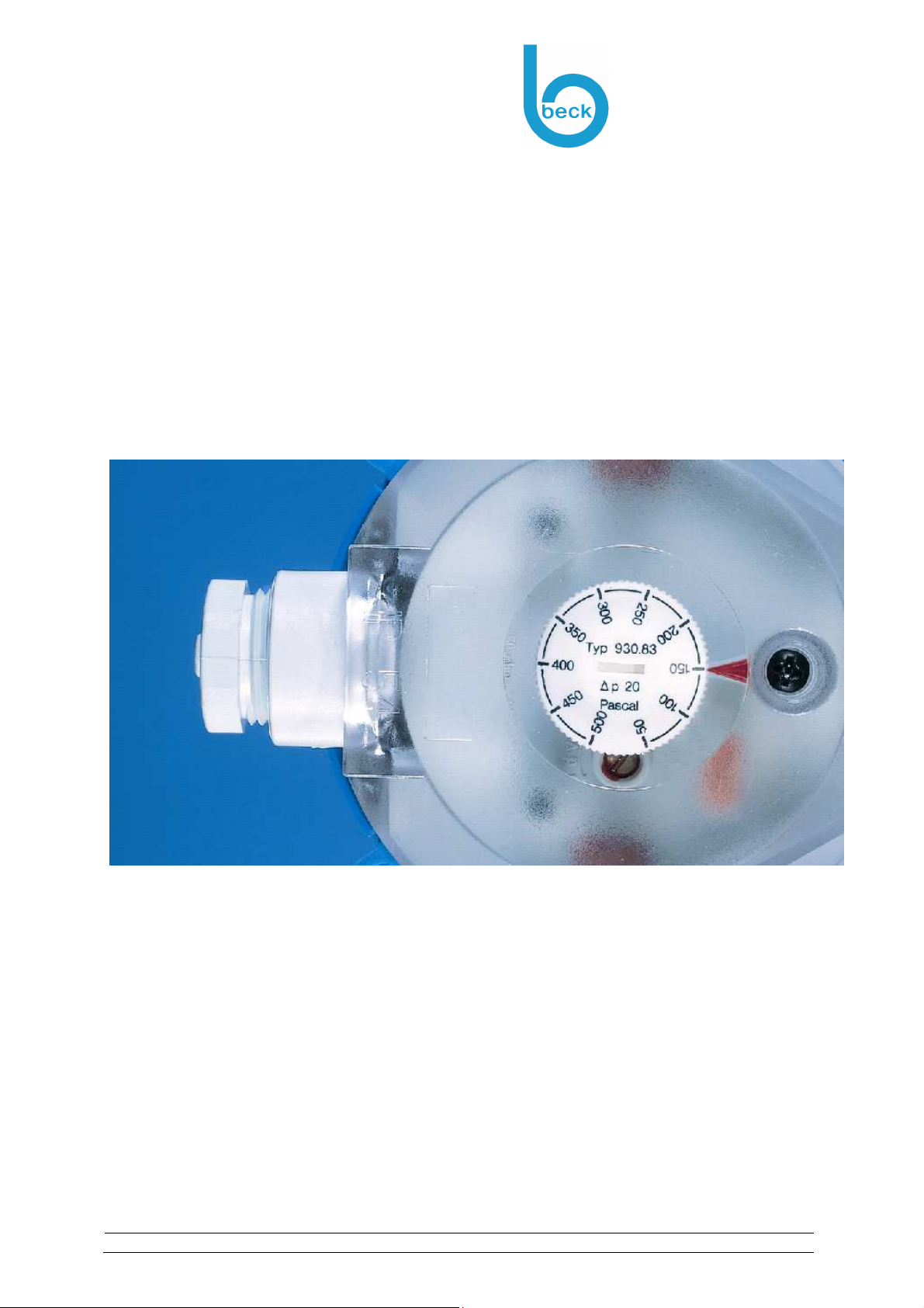
The adjustable
Differential Pressure Switches
Model 930...EX
060925-BA-930-R9-2016_englisch_Druckversion.doc
Ident:
Operating instructions – Pressure Switch - Model-930...EX Rev.9
Page 1 of 18
Page 2

General Instructions
Safety Instructions
Beck GmbH
Druckkontrolltechnik
Ferdinand-Steinbeis-Straße 4
71144 Steinenbronn
1 General instructions ............................................................................................................... 3
1.1 Safety instructions .............................................................................................................. 3
1.1.1 General safety instructions ........................................................................................................... 3
1.1.2 Safety instructions for potentially explosive areas ........................................................................ 4
1.1.3 Notes on environmental protection ............................................................................................... 4
2 Correct purpose of use .......................................................................................................... 5
2.1 Application area .................................................................................................................. 5
2.2 CE conformity ..................................................................................................................... 5
3 Storage and transportation .................................................................................................... 6
3.1 Packaging .......................................................................................................................... 6
3.2 Storage and transportation conditions ................................................................................ 6
4 Installation ............................................................................................................................... 6
4.1 Installation .......................................................................................................................... 7
4.2 Connection ......................................................................................................................... 7
4.2.1 Pressure connections ................................................................................................................... 7
4.2.2 Electrical connections ................................................................................................................... 7
5 Start-up .................................................................................................................................... 9
5.1 Parameterisation ................................................................................................................ 9
6 Maintenance / service ........................................................................................................... 10
6.1 Time intervals ................................................................................................................... 10
6.2 Troubleshooting ................................................................................................................ 10
7 Repairs .................................................................................................................................. 11
8 Dismantling ........................................................................................................................... 11
8.1 Disposal ........................................................................................................................... 12
9 Appendix ............................................................................................................................... 13
9.1 Technical data and dimensioned drawing ......................................................................... 13
9.2 Dimensioned drawings and accessories ........................................................................... 15
9.3 Declaration of Conformity ................................................................................................. 16
9.4 EC design test certification ............................................................................................... 17
9.5 Proof of compliance with explosion protection regulations ................................................ 18
Telephone
Telefax
E-Mail
Internet
VAT-no.
Operating instructions – Pressure Switch - Model-930...EX Rev.9
+49 7157 52 87-0
+49 7157 52 87-83
[email protected]
http://www.beck-sensors.com
DE162391354
Bank Accounts
Kreissparkasse Esslingen-Nürtingen (BLZ 611 500 20) 57 011 970
S.W.I.F.T. ESSLDE66 IBAN: DE33 6115 0020 0057 0119 70
Commerzbank Stuttgart (BLZ 600 400 71) 876 179 300
S.W.I.F.T. COBADEFF600 IBAN: DE70 6004 0071 0876 1793 00
Landesbank Baden-Württemberg (BLZ 600 501 01) 2 214 306
S.W.I.F.T. SOLADEST IBAN: DE36 6005 0101 0002 2143 06
UniCredit Bank - HypoVereinsbank Stuttgart (BLZ 600 202 90) 388 773 332
S.W.I.F.T. HYVEDEMM473 IBAN: DE66 6002 0290 0388 7733 32
Location: Steinenbronn
Amtsgericht Böblingen HRB 6050
Managing Directors: Rainer Beck,
Hans-Peter Funk, Dr. Ernst Thielicke
Page 2 of 18
Page 3
General Instructions
Safety Instructions
Beck GmbH
Druckkontrolltechnik
Ferdinand-Steinbeis-Straße 4
71144 Steinenbronn
1 General Instructions
These operating instructions contain all of the information that is required for an efficient start-up
and safe operation of Model 930...EX pressure switches.
Please read these operating instructions before carrying out installations, start-ups,
maintenance and repairs.
Please ensure that these operating instructions are available at all times.
Please follow the applicable instructions and safety regulations.
All of the work that is described in these operating instructions must be carried out by quali-
fied and authorised experts.
In order to avoid problems, the prescribed maintenance must be carried out at regular in-
tervals by appropriately trained personnel.
Symbols used
The meanings of the symbols that are used are as follows:
Useful, important additional information.
Dangers and safety instructions. Important – please read!
Failure to comply with these instructions can have a detrimental
effect on persons and the operation of the equipment.
Important instructions for use in potentially explosive areas.
Danger – please read!
1.1 Safety Instructions
1.1.1 General safety instructions
Please follow the applicable
Instructions and system-specific regulations (e.g. installation
standards etc.)
Safety regulations and accident prevention regulations
All work must be carried out by authorised and qualified personnel. These qualifications
and authorisations include:
Training, experience and knowledge of the regulations, standards
Only personnel with appropriate product knowledge must carry out start-ups and
maintenance
All repairs must be carried out by personnel who have been authorised to do so by
the manufacturer
Only original parts must be used
Ignoring these operating instructions and making modifications to the equipment are not
permitted and can lead to hazardous situations
Operating instructions – Pressure Switch - Model-930...EX Rev.9
Page 3 of 18
Page 4

General Instructions
Safety Instructions
Beck GmbH
Druckkontrolltechnik
Ferdinand-Steinbeis-Straße 4
71144 Steinenbronn
1.1.2 Safety instructions for potentially explosive areas
The 930..EX pressure switch is suitable for use in areas where there
is a risk of gas or dust explosion
Please follow the applicable
Instructions and system-specific regulations
The labelling of the product must point out that important explosion protection characteris-
tics must be adhered to during use.
G = Gas; D = Dust
Device category 1, 2, 3 or Equipment Protection Level EPL in the 3 zonal areas
Gas parameters: temperature class (T1…T6), explosion group (A, B, C)
Dust parameters: Explosion group (IIIA, B: non-conductive; IIIC: conductive);
Surface temperature, glow and ignition temperature
When work is being performed such as installation, making electrical connections, making
repairs or opening the housing, it must be ensured that
no potentially explosive atmosphere is present
no electrical voltage is present
unintentional activation is ruled out
Dust deposits must be avoided (installation location, protection, cleaning etc.) in order to
prevent dangerous surface temperature increases
For the installation procedure it is necessary to take care that no electrostatic charging will
be done (no high volume flow, cleaning only with damp cloth,…)
It must be ensured that all technical and organisational protective measures are complied
with and that the operation and effectiveness thereof is checked
No modifications must be made to the equipment, since they may lead to a risk of explosion (ignition)
The specifications of the EC design certificate are binding and must be complied with
If the number of the EC design certificate is followed by an “X”, special conditions or deviations from the standard conditions exist
Installation, start-ups and repeated testing may only be carried out by appropriately qualified personnel
The operator must issue a release for work before any activity (installation etc.) is carried
out in potentially explosive areas.
1.1.3 Notes on environmental protection
Please help to protect the environment. Please pay attention to the environmental notes in these
operating instructions:
Chapter 3.1 “Storage“: Handling of packaging materials
Chapter 8.1 “Disposal“: with regard to the product and its components
Operating instructions – Pressure Switch - Model-930...EX Rev.9
Page 4 of 18
Page 5
Correct Purpose of Use
Application area
Beck GmbH
Druckkontrolltechnik
Ferdinand-Steinbeis-Straße 4
71144 Steinenbronn
2 Correct Purpose of Use
2.1 Application area
Purpose of use
The adjustable differential pressure switches have the following main purpose
Monitoring air flow in ventilation shafts for adequate
Operational monitoring by monitoring the air flow of
Liquid level monitoring
The media that are being monitored occur in the following different phases
Gaseous (main application)
Liquid
Use in zones in potentially explosive areas
Pressure switches are used to monitor the pressure difference in
areas of closed systems where there is a risk of gas explosion.
The device may be used in areas where there is a risk of gas or dust explosion
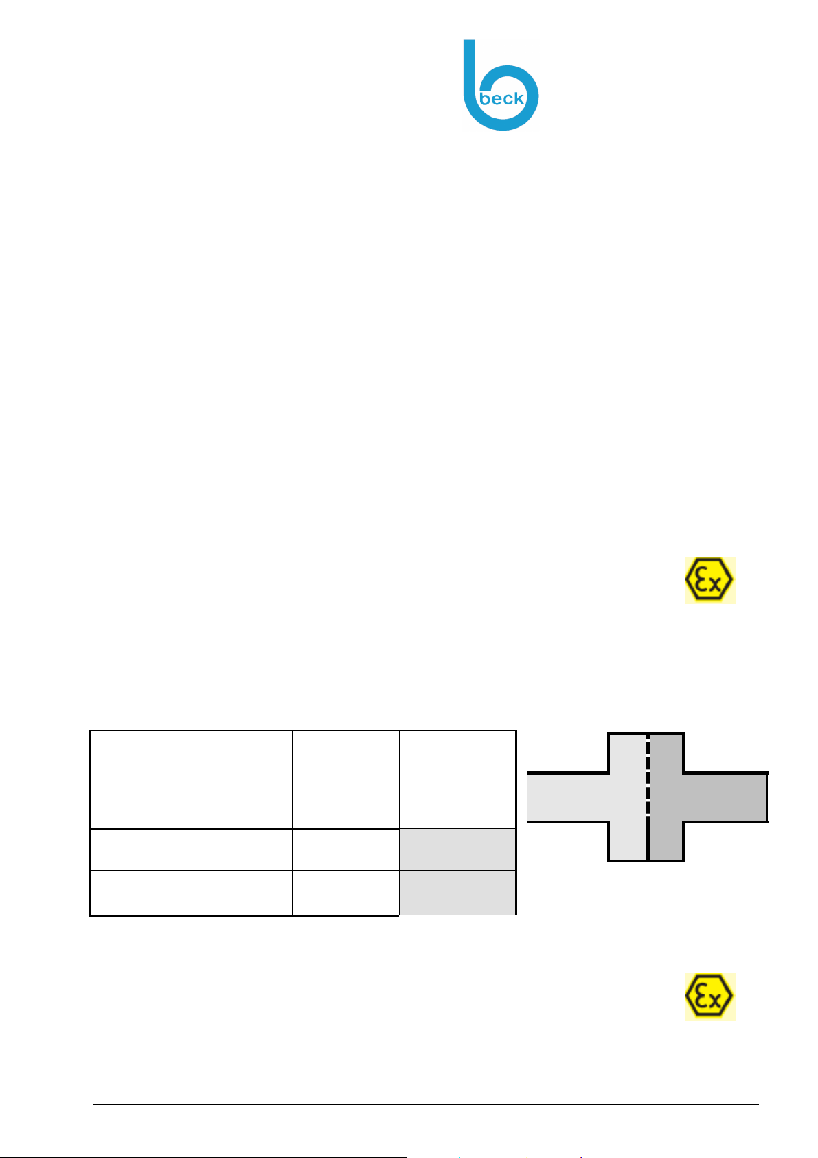
Two separate zonal areas can be connected via pressure connections P1 and P2 (areas 1 and 2)
Zone 1,2 or zone 21,22 may apply to the pressure connections (areas 1 and 2)
The surroundings (area 3) can be zone 1,2 or zone 21,22
Area-1
Zone 1,2 Zone 1,2 Zone 1,2
Zone 21,22 Zone 21,22 Zone 21,22
Dilution of gasses that are hazardous to health or potentially explosive
Air supply (fresh air) and/or exhaust air – extraction of “bad” air
(Air) filters
Air and fire safety flaps
Fans, ventilators
Leak tightness of closed systems
Potentially explosive gasses and dust (natural gas, bio-gas, solvents etc.)
Flammable liquids (petrol, solvent etc.)
Area-2
Surrounding
Area-3
Equipment
category
Equipment
Protection
P1: Area-1
Level EPL
2G
Gb
2D
Db
Area-3
Area-2: P2
2.2 CE Conformity
The product complies with the following European directives:
Explosion protection directive
RoHS directive
Other information and verification can be found in the
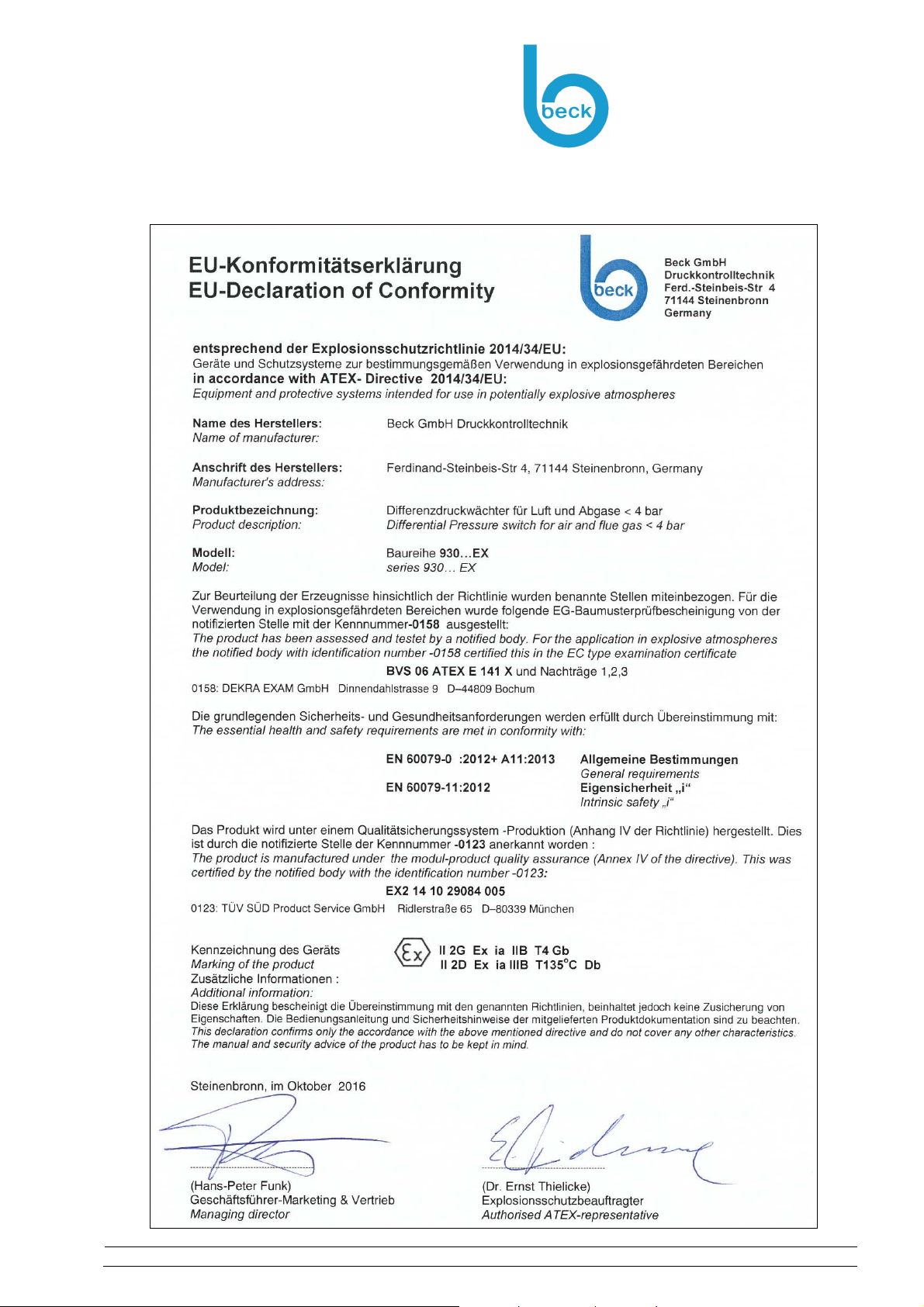
Conformity declaration (see Chapter 9.3)
Operating instructions – Pressure Switch - Model-930...EX Rev.9
Page 5 of 18
Page 6
Storage and Transportation
Packaging
Beck GmbH
Druckkontrolltechnik
Ferdinand-Steinbeis-Straße 4
71144 Steinenbronn
3 Storage and Transportation
3.1 Packaging
The equipment is protected by packaging. The packaging is environmentally compatible and recyclable. The following main materials are used:
Cardboard
PE foam or PE film
Please use appropriate recycling companies to dispose of the packaging
3.2 Storage and Transportation Conditions
The following points must be observed in order to prevent damage:
Avoid severe mechanical stress caused by throwing, stacking and dropping.
Keep out of wet and rainy environments
Do not subject to direct sunlight for long periods
The storage temperature must not be lower than -40 °C or higher than +85 °C
4 Installation
The following checks must be performed prior to installing the equipment:
The equipment must not show signs of damage or obvious modifications
The IP protection class of the equipment must correspond with the usage
and environmental conditions
An operator zone definition must be available
Check whether the equipment category corresponds with the specified zones
With intrinsically safe systems (“i") the “associated operating materials" (barrier) must always be installed outside the potentially explosive area.
The labelling of the product must point out that important explosion protection characteristics must be complied with during use.
G = Gas, D= Dust
Equipment Protection Level
EPL / zone area
Parameters:
Temperature class
(T1...T6)
Explosion group (A, B, C)
Additional information for use in areas where
there is a risk of dust explosion:
The details of the maximum surface
temperature are valid only for a dust allowance of a maximum of 5 mm. At higher dust deposits must be reduced with the surface temperature.
Determining the maximum permissible surface temperature
Dust cloud with ignition temperature -TCL : T
Dust layers with glow temperature -T
The smaller value of both must be considered for the maximum permitted surface temperature. To prevent from dangerous temperature rises dust deposits should be avoided (appropriate mounting position, use of protection covers, regular cleaning..)
For the installation procedure it is necessary to take care that no electrostatic charging will
be done (no high volume flow, cleaning only with damp cloth,…)
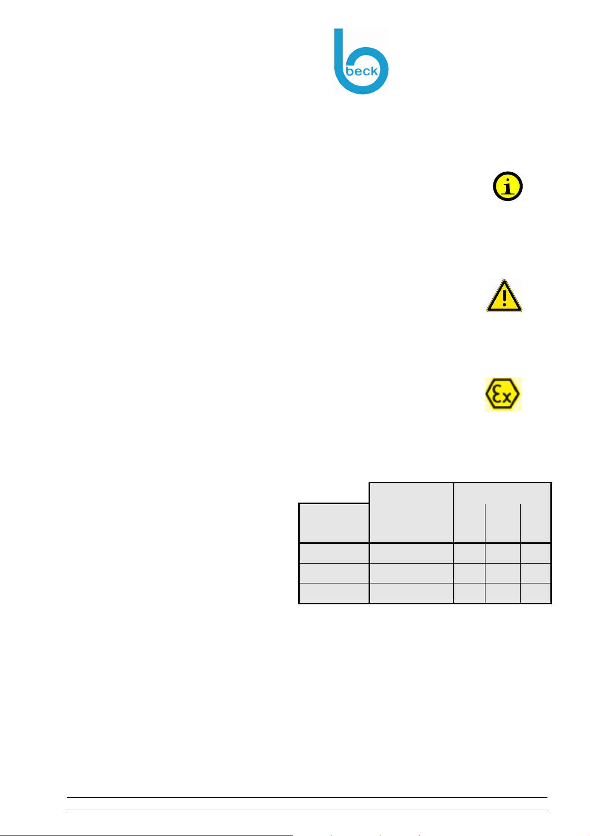
Equipment
category
1 G,D Ga,Da
2 G, D Gb,Db
3 G,D Gc ;Dc
max1
5mm
: T
max2
= T
Equipment Pro-
tection Level
EPL
= 2/3 TCL
– 75oC
5mm
Zone
0
20 1 21 2 22
yes yes yes
no yes yes
no no yes
Operating instructions – Pressure Switch - Model-930...EX Rev.9
Page 6 of 18
Page 7
Installation
Installation
Beck GmbH
Druckkontrolltechnik
Ferdinand-Steinbeis-Straße 4
71144 Steinenbronn
The following standards and directives are useful:
EN 1127-1: Explosion protection – basic concepts and methodology
Standards for areas with risk of gas or dust explosion (“G”, “D”):
EN 60079-10: Classification of potentially explosive areas
EN 60079-14: Electrical installations in potentially explosive areas
EN 60079-17: Inspection and maintenance
EN 60079-25: Intrinsically safe systems
4.1 Installation
Choose the installation location from the following aspects;
Ease of access for installation, connection and operation
Protection from direct effects of the weather, such as rain and sun
The IP protection class of the equipment must suit the ambient conditions
In order to prevent dangerous temperature increases on the surface of the equipment, dust
deposits must be avoided (installation location, protective cover, cleaning measures etc.)
Switching pressure specifications apply to vertical installation which is also the recommended
position with pressure-pipe connections pointing downwards. If the switches are installed
horizontally with AMP connection terminals uppermost, the switching values are approx.
20 Pa higher.
4.2 Connection
4.2.1 Pressure connections
2 plastic pipe connection pieces (6 mm)
P1 +: for connection to higher pressure
P2 -: for connection to lower pressure
4.2.2 Electrical connections
When work is being performed such as installation, making electrical
connection, making repairs or opening the housing, it must be ensured that
No electrical voltage is present
Unintentional activation is not possible
Proceed as follows in potentially explosive areas:
Check whether the equipment category corresponds with the
specified zones
No potentially explosive atmosphere is present
A release for work must have been issued by the operator
Adherence to the applicable regulations and documentation for the equipment
Special notes for intrinsically safe (“i”) systems:
Each intrinsically safe operating material must have an associated operating mate-
rial inserted before it, outside of the potentially explosive zone.
Separate cable routing for intrinsically safe and non-intrinsically safe power circuits.
For operating voltages of less than 42V AC or 60V AC: Intrinsically safe and nonintrinsically safe power circuits can be routed together in this case. This only applies
to safety barrier with galvanic separation.
Separation of intrinsically safe/non-intrinsically safe connecting parts: at least 50mm
(tight string length)
Distance between different intrinsically safe power circuits: at least 6mm
Distances between non-insulated conductive parts leading to connecting parts:
air gap of at least 3mm (housing-terminals-conductor tracks, earth etc.)
Operating instructions – Pressure Switch - Model-930...EX Rev.9
Page 7 of 18
Page 8
Installation
Connection
Power supply
Each intrinsically safe operating material must have an associated
operating material inserted before it, outside of the potentially
explosive zone:
Pay attention to maximum characteristics (U, I, P, L, C):
Compare the information on the specification plate of the appropriate
equipment and the pressure switch 930..EX
Select connecting cables
The following points must be observed when selecting the cable:
Select cable material that complies with the local resistance
requirements (mechanical, chemical)
The outer diameter may be from 5 to 9 mm
Cable cross-section in accordance with electrical power and data sheet
The following points must be observed when selecting cables for intrinsically safe power
circuits:
Diameter of individual conductors: greater than 0.1mm
Insulation strength of the individual wires: greater than 0.2 mm
Test voltage for intrinsically safe cables:
- between wires, shield and earth: 500V AC
Shield: The shield area must be 60% of the surface coverage or twisting
Labelling of intrinsically safe power circuits: colour preferably light blue
L and C cable characteristics must be available
Beck GmbH
Druckkontrolltechnik
Ferdinand-Steinbeis-Straße 4
71144 Steinenbronn
(Ci=110nF/km; Li=1 mH/km)
Cable routing
If there is a risk of mechanical damage, the cable must be provided with additional
protection (protective tube etc.)
The cable diameter must be complied with in order to provide a tight connection in
the cable lead-in.
The screwed cable connection and the screws of the housing cover must be tight-
ened in order to comply with the IP protection class. Over-tightening damages the
housing.
Connecting the cable
Please ensure that the cables that are being connected are not live.
otherwise there is a risk of igniting a potentially explosive atmosphere
Attach the shield
Attach shield at one end (in non-potentially explosive area)
Attach braiding of shield to earth potential over a wide area.
No potential equalisation current must be flowing between potentially
explosive areas and non-potentially explosive areas.
Separation using a capacitor is permitted in this case
for EMC purposes (total max. 10 nF).
Earthing
The external earthing terminal on the housing must be connected
No potential equalisation current must be flowing between potentially explosive are-
Minimum cross-section: 2 x 1.5 mm² or 1 x 4 mm²
Intrinsically safe power circuits: Housings made from metal do not need to be
to the potential equalisation of the potentially explosive area with
low resistance
(removal of electrostatic charge between 0.2-1 MOhms is considered to be earthing)
as and non-potentially explosive areas
earthed.
(If this is necessary anyway – functional earthing, earthing in one location only…)
Operating instructions – Pressure Switch - Model-930...EX Rev.9
Page 8 of 18
Page 9
from
to
Start-up
Parameterisation
Beck GmbH
Druckkontrolltechnik
Ferdinand-Steinbeis-Straße 4
71144 Steinenbronn
Documentation
Operating instructions, conformity declaration, EC design test certificate
System and zonal plan
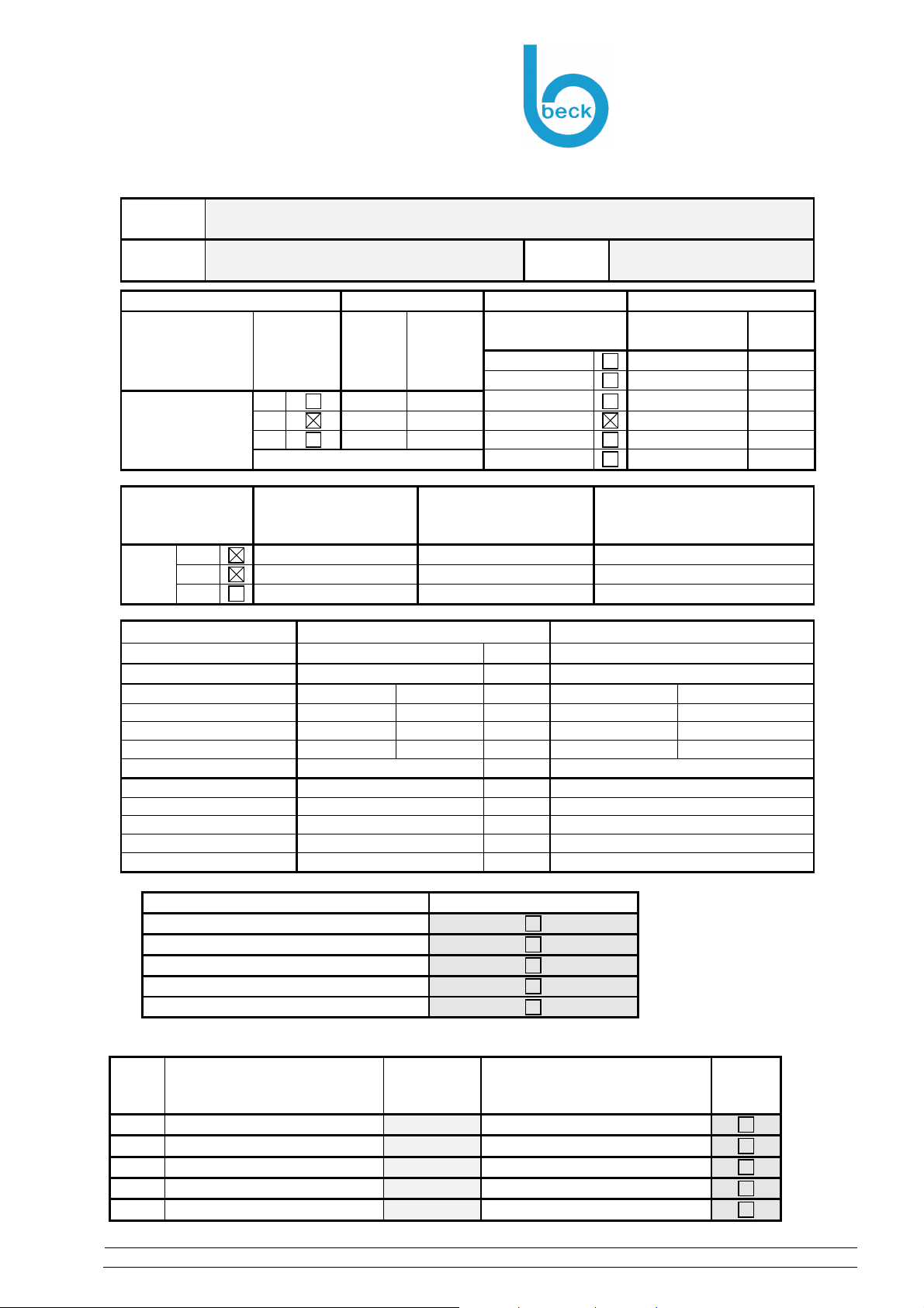
Proof of adherence to explosion protection regulations (see Appendix 9.34)
Equipment selection: category, Equipment Protection Level EPL, temperature
class, explosion group, …
Proof of adherence to intrinsic safety requirements
5 Start-up
Before voltage is applied to the equipment the following checks must be performed:
Check that screws are firmly seated in
Connecting terminals, protective earth conductor terminals and
potential equalisation terminals
Housing cover
Check
The torque of the cable lead-in
The tightness of the seal provided by the cable lead-in
Check whether the equipment is ready for operation
The parameterisation for this application must have been performed
All interfaces such as inputs and outputs for control purposes must be connected
and ready for operation
5.1 Parameterisation
Equipment parameterisation
Define all application-specific parameters.
Adjustment of the pressure ranges
With this pressure switch the pressure can be adjusted without a pressure gauge using a
scaled adjustment knob
The switching differential can also be adjusted with a screwdriver by the adjustment screw
with the identification “-∆p+”
Type Adjustment range
for trip pressure
930.80 EX
930.83 EX
930.84 EX
930.85 EX
930.86 EX
20 300 Pa 10 Pa ±15 %
50 500 Pa 20 Pa ±15 %
30 400 Pa 15 Pa ±15 %
200 1000 Pa 100 Pa ±15 %
500 2500 Pa 150 Pa ±15 %
Switching
differential
Tolerance
band of
930.87 EX
Note:
Switching pressure specifications apply to vertical installation which is also the recommended position
with pressure-pipe connections pointing downwards. If the switches are installed horizontally with AMP
connection terminals uppermost, the switching values are approx. 20 Pa higher.
1000 5000 Pa 250 Pa ±15 %
Once the power supply is applied, the equipment is ready for operation immediately.
Operating instructions – Pressure Switch - Model-930...EX Rev.9
Page 9 of 18
Page 10

Maintenance / Service
Time intervals
Beck GmbH
Druckkontrolltechnik
Ferdinand-Steinbeis-Straße 4
71144 Steinenbronn
6 Maintenance / Service
The equipment can only be guaranteed to operate safely and reliably in the long term if regular
inspections and servicing are carried out. These include the following:
For cleaning the devices it is necessary to take care that no electrostatic charging will be done (no
high volume flow, cleaning only with damp cloth,…)
An inspection includes
Visual inspection
o Mechanical damage
o Non-permitted dust deposits
o Other irregularities or error messages from the equipment
Checking of components (wearing parts) whose functionality or purpose changes and af-
fects the operation of the equipment
Documentation of what was done by whom, and when
Maintenance includes
Functionality checking
o Operating statuses such as alarms etc.
Checking calibration values (= calibration)
o Triggering of alarms by known process parameters (test pressure etc.)
Correction of calibration values (= calibration) must be carried out in the factory
Documentation of what was done by whom, and when
6.1 Time intervals
Inspection:
The condition of the equipment must be checked at regular intervals. The time interval is extremely dependent on the local situation and the degree of use, and must therefore be adapted to requirements. Extremely short time intervals can be specified such as once per day, every new shift
etc.
Defined by the operator in accordance with local requirements
Maintenance
The interval from the applicable usage regulations must be taken into consideration
As a manufacturer we recommend a maximum interval of 1 year
6.2 Troubleshooting
A list of possible faults (fault indications) can be found in the table below.
The table contains an explanation of how to detect faults.
A list of possible causes and remedial measures also follows.
Fault indication
Contact won’t switch
Defective diaphragm
Spring defective
Possible cause
Pressure connection blocked
Pressure outside working range
Measures
Replace pressure switch
Operating instructions – Pressure Switch - Model-930...EX Rev.9
Page 10 of 18
Page 11
Repairs
Troubleshooting
Beck GmbH
Druckkontrolltechnik
Ferdinand-Steinbeis-Straße 4
71144 Steinenbronn
7 Repairs
The following points must be noted before carrying out any work whatsoever on the equipment:
When work is being performed such as installation, making electrical
connections or opening the housing, it must be ensured that
No electrical voltage is present
Unintentional activation is not possible
Repairs must only be carried out by the manufacturer
The following must be observed in potentially explosive areas:
No potentially explosive atmosphere is present
A release for work must have been issued by the operator
The applicable regulations and all documentation for this
equipment must be adhered to
Only original spare parts from the manufacturer must be used
The spare parts must comply with the required equipment category
Interventions that influence explosion protection must only be carried out by experts
A prerequisite is adequate qualification (“capable person”) with regard to explosion
protection and the use of the equipment
8 Dismantling
The following points must be noted before carrying out any work whatsoever on the equipment:
Ensure that the equipment may be removed and that appropriate
replacement measures have been taken.
All of the instructions in chapter 7 “
Operating instructions – Pressure Switch - Model-930...EX Rev.9
Page 11 of 18
Page 12

Dismantling
Disposal
Repairs
Exposed cable (ends) must be marked, and it must be ensured that
” must be followed
Beck GmbH
Druckkontrolltechnik
Ferdinand-Steinbeis-Straße 4
71144 Steinenbronn
No electrical voltage is present
Unintentional activation is not possible
8.1 Disposal
The equipment is made from recyclable materials and is designed to make
the housing and the electronics easy to separate. Please ensure that all
parts are disposed of in accordance with legal regulations.
Please contact us if you cannot dispose of the equipment properly.
Operating instructions – Pressure Switch - Model-930...EX Rev.9
Page 12 of 18
Page 13
Appendix
Technical data and dimensioned drawing
9 Appendix
9.1 Technical data and dimensioned drawing
Temperature ranges
Ambient temperature:
from -20 °C to +85 °C
Medium temperature:
up to +85 °C
Storage temperature:
from -40 °C to +85 °C
Diaphragm material
Silicone; others upon request.
Electrical rating
Values indicated for resistive load
for Gas 2G : 60 mA/30 VDC oder 100 mA/24 VDC
for Dust 2D: 30V; 60mA ; 0.6W
Beck GmbH
Druckkontrolltechnik
Ferdinand-Steinbeis-Straße 4
71144 Steinenbronn
Electrical connection
Cable conduit M20x1.5 or cap nut conduit with cable strain relief
AMP flat plug 6.3 mm x 0.8 mm in accordance with DIN 46244 or push-on screw terminals
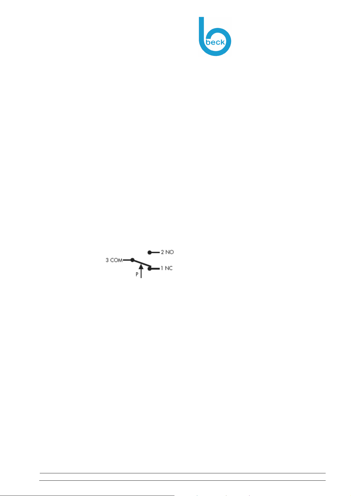
Arrangement of contacts
1 Brake contact
2 Operating contact
3 Power supply line
Protection category
IP 54
(with Cover)
Weight
150 g
Certifications
CE conformity in according with EC explosion protection directive 2014/34/EU.
EC design test certification by the specified EXAM body (ID 0158) with the following ATEX
labelling:
2G Ex ia IIB T4 Gb
2D Ex ia IIIB T135oC Db
Characteristics:
2G : 60 mA/30 VDC oder 100 mA/24 VDC
2D : 30V; 60mA ; 0.6W
Li = 0 mH; Ci = 0 nF
Life
Minimum 106 cycles.
Housing materials
Switch body made of PA 6.6
Cover made of PS
Operating instructions – Pressure Switch - Model-930...EX Rev.9
Page 13 of 18
Page 14

Appendix
Technical data and dimensioned drawing
Types / Pressure ranges
Beck GmbH
Druckkontrolltechnik
Ferdinand-Steinbeis-Straße 4
71144 Steinenbronn
Type Adjustment range
for trip pressure
930.80 EX
930.83 EX
930.84 EX
930.85 EX
930.86 EX
930.87 EX
Note:
Switching pressure specifications apply to vertical installation which is also the recommended position with pressure-pipe connections pointing downwards. If the switches are installed horizontally with
AMP connection terminals uppermost, the switching values are approx. 20 Pa higher.
20 300 Pa 10 Pa ±15 %
50 500 Pa 20 Pa ±15 %
30 400 Pa 15 Pa ±15 %
200 1000 Pa 100 Pa ±15 %
500 2500 Pa 150 Pa ±15 %
1000 5000 Pa 250 Pa ±15 %
Pressure connections:
2 plastic pipe connection pieces
external diameter: 6.0 mm
Switching
differential
Tolerance
band of
Maximum operating pressure:
10 kPa for all pressure ranges
Mounting position
Switching pressure specifications apply to vertical installation which is also the recom-
mended position with pressure-pipe connections pointing downwards. If the switches are installed horizontally with AMP connection terminals uppermost, the switching values are approx. 20 Pa higher.
Accessories
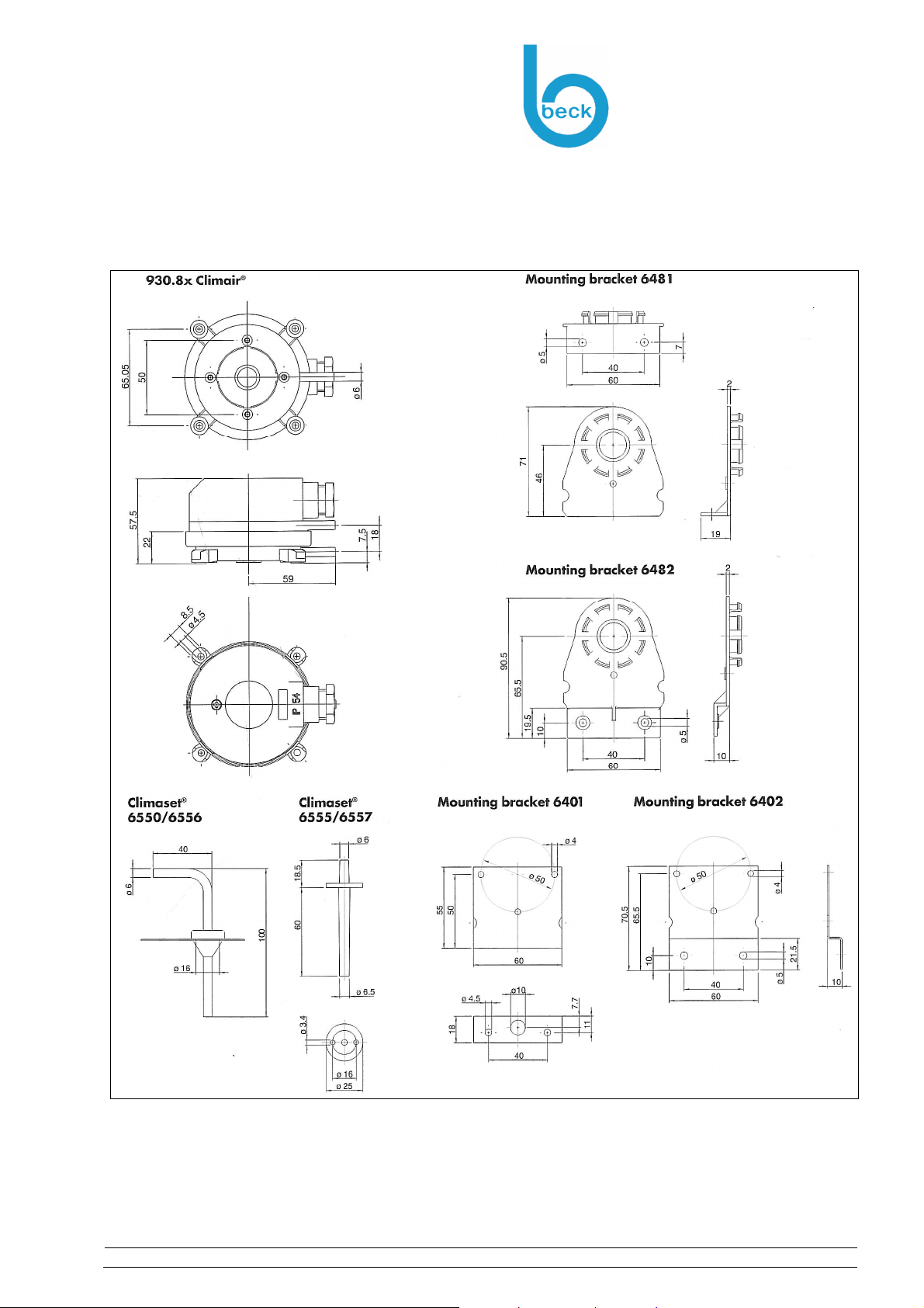
Various mounting brackets
Metal mounting bracket S-shaped
Metal mounting bracket L-shaped
Snap-on plastic bracket S-shaped
Snap-on plastic bracket L-shaped
Various connection kits
Plastic tube for Climaset©
Angled metall pipe for Climaset©
Rubber grommet for Climaset©
Roll with 100 m PVC hose
Various cable conduits
Cap nut conduit including sealing and counter screw
M20x1.5 cable conduit including sealing and counter screw
NPT1/2” cable conduit without counter parts
(see Chapter 9.2)
(see Chapter 9.2)
(see Chapter 9.2)
Operating instructions – Pressure Switch - Model-930...EX Rev.9
Page 14 of 18
Page 15
Appendix
Dimensioned drawings and accessories
9.2 Dimensioned drawings and accessories
Beck GmbH
Druckkontrolltechnik
Ferdinand-Steinbeis-Straße 4
71144 Steinenbronn
Operating instructions – Pressure Switch - Model-930...EX Rev.9
Page 15 of 18
Page 16
Appendix
Declaration of Conformity
9.3 Declaration of Conformity
Beck GmbH
Druckkontrolltechnik
Ferdinand-Steinbeis-Straße 4
71144 Steinenbronn
Operating instructions – Pressure Switch - Model-930...EX Rev.9
Page 16 of 18
Page 17

Appendix
EC design test certification
Beck GmbH
Druckkontrolltechnik
Ferdinand-Steinbeis-Straße 4
71144 Steinenbronn
9.4 EC design test certification
Note: More documentation for EC design test certification you can download from our website.
Operating instructions – Pressure Switch - Model-930...EX Rev.9
Page 17 of 18
Page 18
i,a
i,a
i,a
i,a
i,a
Appendix
Proof of compliance with explosion protection regulations
Beck GmbH
Druckkontrolltechnik
Ferdinand-Steinbeis-Straße 4
71144 Steinenbronn
9.5 Proof of compliance with explosion protection regulations
Project
Name
Date
Requirement Complies with Requirement Complies with
Application area
Explosion
group
Requirement
II
(Gas)
III
(Dust)
A
B A,B,C
C A,B,C
Permitted Equip.
Protection Level
II
(Gas)
A
A,B
A,B,C
Certified for
Temperature
class (Gas)
T1
T2
T3
T4
T5
T6
Temperature
class (Gas)
Temp.
(Dust)
T1 400oC
T1-T2 300oC
T1-T3 200oC
T1-T4 135oC
T1-T5 100oC
T1-T6 85oC
Ignition protection class
EPL (G=Gases)
Zone 2,22
1,21
0,20
CHARACTERICTICS
Designation
Gc,Dc Zone 2/22
Gb,Db Zone 1,2 /21,22 Ex ia IIB / Ex ia IIIB
Ga,Da Zone 0,1,2/ 20,21,22
Intrinsically safe operating materials
Pressure switch Cable
Associated operating materials
Switch amplifier
Model 930 ..EX
Application area 2G 2D
Ignition protection class Ex ia … Gb Ex ia…Db
Explosion group IIB IIIB
Temperature class T4 T135C
Certification BVS 06 ATEX E141X
U
30V
I
P
600mW
L
0 1mH
C
0
Kabelkennwerte: 1
mH
/km ; 110 nF/km
60mA
Requirement complied with
Application area
Ignition protection class
Explosion group
Temperature class
Equipment Protection Level EPL/Zone
Proof of intrinsic safety
Associated operating mate-
rials
(barriers)
U
I
P
L
C
Operating instructions – Pressure Switch - Model-930...EX Rev.9
Require-
ment
≤
≤
≤
≥
≥
Intrinsically safe operating
materials
(including cable)
30V
60mA
600mA
1mH
0,1µF
(1km cable)
(1km cable)
Compliant
Page 18 of 18
 Loading...